EP2520101B1 - Ultraschallwandler mit niedrigem profil - Google Patents
Ultraschallwandler mit niedrigem profil Download PDFInfo
- Publication number
- EP2520101B1 EP2520101B1 EP11728555.1A EP11728555A EP2520101B1 EP 2520101 B1 EP2520101 B1 EP 2520101B1 EP 11728555 A EP11728555 A EP 11728555A EP 2520101 B1 EP2520101 B1 EP 2520101B1
- Authority
- EP
- European Patent Office
- Prior art keywords
- component
- ultrasound
- lens
- transducer
- piezoelectric
- Prior art date
- Legal status (The legal status is an assumption and is not a legal conclusion. Google has not performed a legal analysis and makes no representation as to the accuracy of the status listed.)
- Active
Links
Images


Classifications
-
- A—HUMAN NECESSITIES
- A61—MEDICAL OR VETERINARY SCIENCE; HYGIENE
- A61N—ELECTROTHERAPY; MAGNETOTHERAPY; RADIATION THERAPY; ULTRASOUND THERAPY
- A61N7/00—Ultrasound therapy
-
- A—HUMAN NECESSITIES
- A61—MEDICAL OR VETERINARY SCIENCE; HYGIENE
- A61B—DIAGNOSIS; SURGERY; IDENTIFICATION
- A61B8/00—Diagnosis using ultrasonic, sonic or infrasonic waves
- A61B8/42—Details of probe positioning or probe attachment to the patient
- A61B8/4209—Details of probe positioning or probe attachment to the patient by using holders, e.g. positioning frames
- A61B8/4227—Details of probe positioning or probe attachment to the patient by using holders, e.g. positioning frames characterised by straps, belts, cuffs or braces
-
- A—HUMAN NECESSITIES
- A61—MEDICAL OR VETERINARY SCIENCE; HYGIENE
- A61B—DIAGNOSIS; SURGERY; IDENTIFICATION
- A61B8/00—Diagnosis using ultrasonic, sonic or infrasonic waves
- A61B8/42—Details of probe positioning or probe attachment to the patient
- A61B8/4209—Details of probe positioning or probe attachment to the patient by using holders, e.g. positioning frames
- A61B8/4236—Details of probe positioning or probe attachment to the patient by using holders, e.g. positioning frames characterised by adhesive patches
-
- A—HUMAN NECESSITIES
- A61—MEDICAL OR VETERINARY SCIENCE; HYGIENE
- A61B—DIAGNOSIS; SURGERY; IDENTIFICATION
- A61B8/00—Diagnosis using ultrasonic, sonic or infrasonic waves
- A61B8/42—Details of probe positioning or probe attachment to the patient
- A61B8/4272—Details of probe positioning or probe attachment to the patient involving the acoustic interface between the transducer and the tissue
- A61B8/4281—Details of probe positioning or probe attachment to the patient involving the acoustic interface between the transducer and the tissue characterised by sound-transmitting media or devices for coupling the transducer to the tissue
-
- A—HUMAN NECESSITIES
- A61—MEDICAL OR VETERINARY SCIENCE; HYGIENE
- A61B—DIAGNOSIS; SURGERY; IDENTIFICATION
- A61B17/00—Surgical instruments, devices or methods
- A61B17/22—Implements for squeezing-off ulcers or the like on inner organs of the body; Implements for scraping-out cavities of body organs, e.g. bones; for invasive removal or destruction of calculus using mechanical vibrations; for removing obstructions in blood vessels, not otherwise provided for
- A61B17/225—Implements for squeezing-off ulcers or the like on inner organs of the body; Implements for scraping-out cavities of body organs, e.g. bones; for invasive removal or destruction of calculus using mechanical vibrations; for removing obstructions in blood vessels, not otherwise provided for for extracorporeal shock wave lithotripsy [ESWL], e.g. by using ultrasonic waves
- A61B17/2251—Implements for squeezing-off ulcers or the like on inner organs of the body; Implements for scraping-out cavities of body organs, e.g. bones; for invasive removal or destruction of calculus using mechanical vibrations; for removing obstructions in blood vessels, not otherwise provided for for extracorporeal shock wave lithotripsy [ESWL], e.g. by using ultrasonic waves characterised by coupling elements between the apparatus, e.g. shock wave apparatus or locating means, and the patient, e.g. details of bags, pressure control of bag on patient
-
- A—HUMAN NECESSITIES
- A61—MEDICAL OR VETERINARY SCIENCE; HYGIENE
- A61B—DIAGNOSIS; SURGERY; IDENTIFICATION
- A61B17/00—Surgical instruments, devices or methods
- A61B2017/00681—Aspects not otherwise provided for
- A61B2017/00734—Aspects not otherwise provided for battery operated
-
- A—HUMAN NECESSITIES
- A61—MEDICAL OR VETERINARY SCIENCE; HYGIENE
- A61B—DIAGNOSIS; SURGERY; IDENTIFICATION
- A61B17/00—Surgical instruments, devices or methods
- A61B17/22—Implements for squeezing-off ulcers or the like on inner organs of the body; Implements for scraping-out cavities of body organs, e.g. bones; for invasive removal or destruction of calculus using mechanical vibrations; for removing obstructions in blood vessels, not otherwise provided for
- A61B17/225—Implements for squeezing-off ulcers or the like on inner organs of the body; Implements for scraping-out cavities of body organs, e.g. bones; for invasive removal or destruction of calculus using mechanical vibrations; for removing obstructions in blood vessels, not otherwise provided for for extracorporeal shock wave lithotripsy [ESWL], e.g. by using ultrasonic waves
- A61B17/2251—Implements for squeezing-off ulcers or the like on inner organs of the body; Implements for scraping-out cavities of body organs, e.g. bones; for invasive removal or destruction of calculus using mechanical vibrations; for removing obstructions in blood vessels, not otherwise provided for for extracorporeal shock wave lithotripsy [ESWL], e.g. by using ultrasonic waves characterised by coupling elements between the apparatus, e.g. shock wave apparatus or locating means, and the patient, e.g. details of bags, pressure control of bag on patient
- A61B2017/2253—Implements for squeezing-off ulcers or the like on inner organs of the body; Implements for scraping-out cavities of body organs, e.g. bones; for invasive removal or destruction of calculus using mechanical vibrations; for removing obstructions in blood vessels, not otherwise provided for for extracorporeal shock wave lithotripsy [ESWL], e.g. by using ultrasonic waves characterised by coupling elements between the apparatus, e.g. shock wave apparatus or locating means, and the patient, e.g. details of bags, pressure control of bag on patient using a coupling gel or liquid
-
- A—HUMAN NECESSITIES
- A61—MEDICAL OR VETERINARY SCIENCE; HYGIENE
- A61B—DIAGNOSIS; SURGERY; IDENTIFICATION
- A61B34/00—Computer-aided surgery; Manipulators or robots specially adapted for use in surgery
- A61B34/10—Computer-aided planning, simulation or modelling of surgical operations
- A61B2034/107—Visualisation of planned trajectories or target regions
-
- A—HUMAN NECESSITIES
- A61—MEDICAL OR VETERINARY SCIENCE; HYGIENE
- A61B—DIAGNOSIS; SURGERY; IDENTIFICATION
- A61B34/00—Computer-aided surgery; Manipulators or robots specially adapted for use in surgery
- A61B34/30—Surgical robots
- A61B2034/301—Surgical robots for introducing or steering flexible instruments inserted into the body, e.g. catheters or endoscopes
-
- A—HUMAN NECESSITIES
- A61—MEDICAL OR VETERINARY SCIENCE; HYGIENE
- A61B—DIAGNOSIS; SURGERY; IDENTIFICATION
- A61B34/00—Computer-aided surgery; Manipulators or robots specially adapted for use in surgery
- A61B34/30—Surgical robots
- A61B2034/303—Surgical robots specifically adapted for manipulations within body lumens, e.g. within lumen of gut, spine, or blood vessels
-
- A—HUMAN NECESSITIES
- A61—MEDICAL OR VETERINARY SCIENCE; HYGIENE
- A61B—DIAGNOSIS; SURGERY; IDENTIFICATION
- A61B34/00—Computer-aided surgery; Manipulators or robots specially adapted for use in surgery
- A61B34/10—Computer-aided planning, simulation or modelling of surgical operations
-
- A—HUMAN NECESSITIES
- A61—MEDICAL OR VETERINARY SCIENCE; HYGIENE
- A61B—DIAGNOSIS; SURGERY; IDENTIFICATION
- A61B34/00—Computer-aided surgery; Manipulators or robots specially adapted for use in surgery
- A61B34/30—Surgical robots
-
- A—HUMAN NECESSITIES
- A61—MEDICAL OR VETERINARY SCIENCE; HYGIENE
- A61B—DIAGNOSIS; SURGERY; IDENTIFICATION
- A61B8/00—Diagnosis using ultrasonic, sonic or infrasonic waves
- A61B8/44—Constructional features of the ultrasonic, sonic or infrasonic diagnostic device
-
- A—HUMAN NECESSITIES
- A61—MEDICAL OR VETERINARY SCIENCE; HYGIENE
- A61B—DIAGNOSIS; SURGERY; IDENTIFICATION
- A61B8/00—Diagnosis using ultrasonic, sonic or infrasonic waves
- A61B8/44—Constructional features of the ultrasonic, sonic or infrasonic diagnostic device
- A61B8/4427—Device being portable or laptop-like
-
- A—HUMAN NECESSITIES
- A61—MEDICAL OR VETERINARY SCIENCE; HYGIENE
- A61N—ELECTROTHERAPY; MAGNETOTHERAPY; RADIATION THERAPY; ULTRASOUND THERAPY
- A61N7/00—Ultrasound therapy
- A61N2007/0004—Applications of ultrasound therapy
- A61N2007/0034—Skin treatment
-
- A—HUMAN NECESSITIES
- A61—MEDICAL OR VETERINARY SCIENCE; HYGIENE
- A61N—ELECTROTHERAPY; MAGNETOTHERAPY; RADIATION THERAPY; ULTRASOUND THERAPY
- A61N7/00—Ultrasound therapy
- A61N2007/0056—Beam shaping elements
- A61N2007/006—Lenses
-
- A—HUMAN NECESSITIES
- A61—MEDICAL OR VETERINARY SCIENCE; HYGIENE
- A61N—ELECTROTHERAPY; MAGNETOTHERAPY; RADIATION THERAPY; ULTRASOUND THERAPY
- A61N7/00—Ultrasound therapy
- A61N2007/0078—Ultrasound therapy with multiple treatment transducers
-
- A—HUMAN NECESSITIES
- A61—MEDICAL OR VETERINARY SCIENCE; HYGIENE
- A61N—ELECTROTHERAPY; MAGNETOTHERAPY; RADIATION THERAPY; ULTRASOUND THERAPY
- A61N7/00—Ultrasound therapy
- A61N2007/0086—Beam steering
- A61N2007/0091—Beam steering with moving parts, e.g. transducers, lenses, reflectors
-
- A—HUMAN NECESSITIES
- A61—MEDICAL OR VETERINARY SCIENCE; HYGIENE
- A61N—ELECTROTHERAPY; MAGNETOTHERAPY; RADIATION THERAPY; ULTRASOUND THERAPY
- A61N7/00—Ultrasound therapy
- A61N2007/0086—Beam steering
- A61N2007/0095—Beam steering by modifying an excitation signal
-
- Y—GENERAL TAGGING OF NEW TECHNOLOGICAL DEVELOPMENTS; GENERAL TAGGING OF CROSS-SECTIONAL TECHNOLOGIES SPANNING OVER SEVERAL SECTIONS OF THE IPC; TECHNICAL SUBJECTS COVERED BY FORMER USPC CROSS-REFERENCE ART COLLECTIONS [XRACs] AND DIGESTS
- Y10—TECHNICAL SUBJECTS COVERED BY FORMER USPC
- Y10T—TECHNICAL SUBJECTS COVERED BY FORMER US CLASSIFICATION
- Y10T29/00—Metal working
- Y10T29/49—Method of mechanical manufacture
- Y10T29/49002—Electrical device making
- Y10T29/49005—Acoustic transducer
Definitions
- the present invention relates to a low-profile ultrasound transducer and a method of manufacturing a low-profile ultrasound transducer.
- Traditional therapeutic ultrasound generation technologies have a number of deficiencies that prohibit their use in portable ultrasound delivery devices.
- current therapeutic ultrasound generation technologies are, at the smallest, shoebox-sized devices that include a user interface, power generation circuitry, and a separate hand wand transducer attached via a cable.
- the devices vary in shape and size, but generally are 2.72 - 9.07 kg (6-20 pounds).
- Such devices also require wall power and administer ultrasound energies from 0-4 Watts and at frequencies of from 1-3 MHz. The energy from the transducers of such devices is applied to penetrate into the tissue and administer ultrasound.
- Traditional ultrasound therapies are for a short duration (e.g., 5-20 minutes) where they are physically applied by hand for the entire treatment period.
- Other purported therapeutic ultrasound technologies purport to be portable, but are capable of producing only surface low-frequency 90 kHz ultrasound waves.
- a portable (i.e., wearable) therapeutic ultrasound device that is able to safely deliver low to high frequency ultrasound (i.e., about 10 kHz to about 40 MHz) ultrasound energy deep into tissue.
- therapeutic ultrasound devices in the art are not able to be used for long periods, due to safety concerns, the non-portable size of the devices or the need for external power sources or the need for the device to be actively applied by the user.
- WO 2007/035529 discloses an ultrasound therapy probe including a thin-profile therapy head for implementing therapeutic procedures in confined spaces.
- the thin-profile is achieved by incorporating a cooling fluid channel about a periphery of at least a portion of the housing.
- the present invention is directed to overcoming these and other deficiencies in the art.
- the portable ultrasound system includes an energy generating module operative to generate a driving signal that can be transformed into ultrasonic energy, where the energy generating module includes a power source, an oscillator, and a driver component.
- the portable ultrasound system also includes an ultrasound transducer having a piezoelectric component and a lens component. The ultrasound transducer is operative to receive the driving signal from the energy generating module, to transform the driving signal into ultrasonic energy, and to control the direction of the ultrasonic energy emitted from the ultrasound transducer.
- the implantable device for use in generating ultrasound energy within a patient.
- the implantable device includes the portable ultrasound system of the present invention and an implantable component configured to contain the system.
- the biocompatible device for use in generating ultrasound energy within a patient.
- the biocompatible device includes an energy generating module operative to generate a driving signal that can be transformed into ultrasonic energy, where the energy generating module includes a power source, an oscillator, and a driver component.
- the biocompatible device also includes a piezoelectric component operative to receive the driving signal from the energy generating module, to transform the driving signal into low intensity therapeutic ultrasonic energy, and to emit the low intensity therapeutic ultrasonic energy.
- the biocompatible device also includes a biocompatible component configured to contain the energy generating module and the piezoelectric component.
- the low-profile ultrasound transducer includes a piezoelectric component operative to receive a driving signal from an energy generating module and to emit the driving signal as ultrasonic energy.
- the piezoelectric component has a front surface and a back surface, and the energy generating module includes a plurality of electronic components.
- the low-profile ultrasound transducer also includes a lens component directly or indirectly deposited on the front surface of the piezoelectric component.
- the lens component includes a lens portion and a support portion.
- the lens portion of the lens component is configured to control the direction and wave pattern of the ultrasonic energy emitted from the piezoelectric component.
- the support portion of the lens component is configured to hold the piezoelectric component in place and to provide a chamber for housing at least one electronic component of the energy generating module.
- This method involves providing a piezoelectric component operative to receive a driving signal from an energy generating module and to emit the driving signal as ultrasonic energy, the piezoelectric component having a front surface and a back surface, and the energy generating module including a plurality of electronic components.
- the method also involves providing a lens component that includes a lens portion and a support portion.
- the method also involves directly or indirectly depositing the lens component on the front surface of the piezoelectric component, where the lens portion of the lens component is configured to control the direction and wave pattern of the ultrasonic energy emitted from the piezoelectric component, and where the support portion of the lens component is configured to hold the piezoelectric component in place and to provide a chamber for housing at least one electronic component of the energy generating module.
- the present invention's portable ultrasound system and low-profile ultrasound transducer used in an ultrasound system can be used for various applications, some of which are briefly described as follows:
- This method involves providing a portable ultrasound system of the present invention or a plurality of the systems in the form of an array, and then applying therapeutic ultrasound energy to a target area of a subject, where the therapeutic ultrasound energy is generated by the system or array of systems.
- This method involves providing a portable ultrasound system of the present invention or a plurality of the systems in the form of an array, and applying ultrasound energy to a target surface of a subject, where the ultrasound energy is generated by the system or array of systems.
- This method involves providing a portable ultrasound system of the present invention or a plurality of the systems in the form of an array, where the deliverable component includes a drug to be delivered to a subject, and applying ultrasound energy to a surface of a subject along with the deliverable component, where the ultrasound energy is generated by the system or array of systems.
- This method involves administering to a subject a biocompatible device of the present invention, where the biocompatible component is in the form of an ingestible device that includes a drug to be delivered to the subject, and where the device is effective to generate ultrasound energy in order to facilitate internal delivery of the drug to the subject.
- the low-profile ultrasound transducer of the present invention can be used as the transducer in the system.
- the present invention is effective in providing a therapeutic ultrasound technology that packages ultrasound therapy options into a device that can be used all day long, with little to no discomfort, and little or no reduction of mobility.
- the device enables the application of ultrasound in a range of medical and non-medical applications in a small compact platform.
- the present invention provides, inter alia, a wearable therapeutic ultrasound system that is convenient and that can be used continuously for hours at a time.
- an ultra-portable, complete therapeutic ultrasound device that can be configured to include a power-source, ultrasound driver, and ultrasound transducer, and that can be controlled by the user in a single working unit.
- the device of the present invention produces ultrasound energies covering the therapeutic physiotherapy and drug delivery power ranges and frequencies, while still being much smaller in size and untethered by wires for eternal power as compared to current therapeutic ultrasound technologies.
- the complete therapeutic ultrasound device of the present invention is small enough to be placed inside a patch and can be used to apply ultrasound energy any place on the body for ultrasound administration.
- a wearable therapeutic ultrasound device that has the ability to provide ultrasound energy for extended periods of time during normal everyday activity. It therefore enables the safe use of ultrasound for healing, pain, drug delivery, and other applications over long periods of time. Further, this ultrasound system or device can be used for wireless energy transfer and recharging of implantable.
- the invention could also be used for disposable ultrasound energy sources for military applications of sonar, mine detection, etc.
- the present invention can be used for miniature and portable sources of ultrasound generation, i.e., for military, medical, and industrial applications.
- the present invention can be used for sonar and as a low-cost portable diagnostic tool.
- the invention may also be used for tissue healing, wound healing, pain relief, and the like.
- the present invention relates to a low-profile ultrasound transducer that are suitable for a number of ultrasound applications, including, for example, therapeutic ultrasound, wireless energy transfer and charging on internal devices, brain drug delivery, thermal drug delivery, cosmetic applications, bone healing, and others.
- the portable ultrasound system and low-profile ultrasound transducer are particularly suited for tissue stimulation, ultrasound therapy, healing, regenerative medicine, drug delivery, ocular drug delivery, and as portable sources of ultrasound.
- the portable ultrasound system is operative to emit ultrasonic energy as pulsed, continuous, or both pulsed and continuous ultrasonic energy.
- the portable ultrasound system is operative to ultrasonic energy having an acoustic intensity ranging from between about 10 mW/cm 2 and about 5 W/cm 2 .
- the portable ultrasound system of the present invention requires relatively low power and voltage to produce ultrasound in this acoustic intensity range. This enables the portable ultrasound system to be used in wide range of ultrasound applications, particularly those applications that require portability and that do not require trained medical or therapeutic personnel.
- the portable ultrasound system and the low-profile ultrasound transducer of the present invention are well suited for use together, with the low-profile ultrasound transducer being used in the portable ultrasound system.
- other transducers may also be used in the portable ultrasound system of the present invention.
- the portable ultrasound system is disclosed, followed by the low-profile ultrasound transducer.
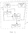
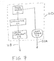
- energy generating module 20 can be provided in various operative configurations. Each configuration is designed to provide a voltage efficiency of voltage load input (from power source 21) to voltage load output (exiting driver component 23) of at least 80 percent. All voltage efficiencies of at least 80 percent and above, including, for example, but not limited to, ranges from about 80 percent to more than 99 percent voltage efficiency are included.
- energy generating module 20 includes power source 21 coupled to both oscillator 22 and driver component 23, so that power source 21 provides power to both oscillator 22 and driver component 23.
- energy generating module 20 can further include voltage controller 24, which is operative to control power distribution (e.g., as an on/off power switch) from power source 21 to oscillator 22 and driver component 23.
- voltage controller 24 can include on/off controller 24a coupled to transistor switch 24b.
- a suitable on/off controller or supervisory IC 24a can include, without limitation, LTC2951ITS8-2, TPS3707-30DGN, and the like.
- a suitable transistor switch 24b can include, without limitation, MOSFETs (e.g., FDY102PZ, EL7158S, Si9433BDY, and the like) configured to be used as power switches.
- oscillator 22 is configured to operate in a range of between about 0 MHz and about 40 MHz at voltages ranging from between about 0 and 5 volts. In one embodiment, the oscillator can be configured to operate from about 0-5 volts, while the driver can be configured to operate from about 0-24 volts to power the ultrasound transducer. In low intensity treatments, for example, the driver can be configured to operate at about 0-5 volts.
- the portable ultrasound system can run on power generated at between about 0.1 and about 24 volts.
- power source 21 can include any device operative to generate between about 0.1 and about 24 volts.
- suitable power sources 21 can include, without limitation, various types of batteries, including non-rechargeable and rechargeable batteries. Examples of suitable batteries include, without limitation, double A batteries (AA), Lithium ion batteries, and the like.
- the portable ultrasound system of the present invention is configured so that it can run on a single, off-the-shelf battery for maximum portability, or configured to run on more than one battery where portability or size of the system is less important to the user.
- driver component 23 can include at least one pin driver 23a. As shown in FIGS. 3B-3D , in particular embodiments, driver component 23 can include two pin drivers 23a arranged in parallel. Further embodiments can include more than two pin drivers 23a, arranged in parallel, in series, or in both parallel and series.
- FIG. 3C and FIG. 3D illustrate detailed circuitry of particular embodiments of energy generating module 20. However, the present circuitry is not limited to circuitry configurations illustrated in FIGS. 3C-3D , which are being provided only as illustrative examples.
- a further embodiment can include temperature sensor 25 (e.g., SA56004BDP,118) as part of energy generating module 20.
- Suitable temperature sensors 25 can include any device operative to monitor heat generated during use of portable ultrasound system 10, and to turn off or cancel power generation from power source 21 when the temperature of portable ultrasound system 10 reaches a predetermined high temperature cut-off point. Thermal cut-offs that turn power off when the temperature rises beyond a set point. Suitable temperature sensors 25 are known in the art. As shown in FIG. 22 , temperature sensor 25 can be deposited on or near piezoelectric component 60.
- the portable ultrasound system is useful for applying ultrasonic energy to a target area (e.g., of a human or animal subject) in a targeted and controlled manner.
- a target area e.g., of a human or animal subject
- the portable ultrasound system is effective in controlling the direction and wave pattern of the ultrasonic energy emitted from the portable ultrasound system.
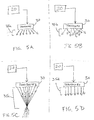
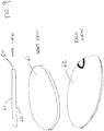
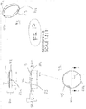
- ultrasound transducer 30 can be configured to control the direction of emitted ultrasonic energy 35 in various wave patterns, including diverging wave pattern 35a ( FIG. 5A ), scattering wave pattern 35b ( FIG. 5B ), focused wave pattern 35c ( FIG. 5C ), and parallel wave pattern 35d ( FIG. 5D ).
- lens component 70 of ultrasound transducer 30 can be configured to include an outer lens surface that as follows: convex lens 74 for diverging wave patterns 35a ( FIG. 6A ), ridged lens 75 for scattering wave patterns 35b ( FIG. 6B ), concave lens 77 for focused wave patterns 35c ( FIG. 6C ), or flat lens 76 for parallel wave patterns 35d ( FIG. 6D ). Also, the present invention can use a directed lens to take into account directing ultrasound waves into a subject's body at specific angles (e.g., toward a joint within the body).
- energy generating module 20 can be configured to also include light source 52, which can be used to emit light energy 52a.
- Light source 52 is integrated into energy generating module 20 so that it is powered by power source 21.
- Light source 52 can include any device operative to convert electrical energy received from power source 21 into light energy 52a.
- light source 52 can include a light-emitting diode (LED).
- the emitted light energy 52a can be useful for various purposes, including, without limitation, as heat therapy, light therapy, light signaling, lighting, and decorative purposes.
- lens component 70 can be configured to operate to allow both ultrasonic energy 35 and light energy 52a to be emitted from ultrasound transducer 30 to pass through lens component 70.
- lens component 70 can also be configured to allow only ultrasonic energy 35 to pass through lens component 70.
- Various materials can be used for lens component 70, including, without limitation, the following materials: Ultem, Rexolite, Ahrilic, Plexiglass, and the like. Suitable materials for passing only ultrasonic energy 35 through lens component 70 are known in the art and contemplated by the present invention. Suitable materials for passing both ultrasonic energy 35 and light energy 52a through lens component 70 are also known in the art and contemplated by the present invention. Further, as shown in FIG.
- lens component 70 can be configured so that only a portion 56 of it is suitable for passing both ultrasonic energy 35 and light energy 52a therethrough, with the rest of lens component 70 configured to allow for passing of only ultrasonic energy 35 therethrough.
- wavy arrowed lines generally depict light energy 52a and straight arrowed lines generally depict ultrasonic energy 35 or driving signal 28.
- piezoelectric component 60 includes front surface 61 and back surface 62.
- Front surface 61 is the portion of piezoelectric component 60 from which ultrasonic energy 35 is emitted or both ultrasonic energy 35 and light energy 52a are emitted.
- Back surface 62 is the portion of piezoelectric component 60 that is opposite to front surface 61.
- lens component 70 can be configured to include a plurality of ports 55 through which deliverable component 54 can pass during ultrasound energy generation.
- Ports 55 can be of various sizes and arranged in various patterns.
- FIGS. 10A-10E are only provided as illustrative examples of the types of patterns and sizes of ports 55, but they are not being provided to limit the present invention only to those patterns depicted in the drawings.
- Deliverable component 54 can include any material that can pass through a hole or plurality of holes in piezoelectric component 60 in response to ultrasonic energy generated by portable ultrasound system 10.
- deliverable component 54 can be any ultrasound medium.
- Suitable examples of deliverable components 54 can include, without limitation, ultrasound gel, drugs, cosmetics, anti-bacterial compositions, disinfectants, lotions, etc., or a combination thereof.
- deliverable component 54 can be in the form of a drug powder mixed into an ultrasound gel, or any other suitable ultrasound medium.
- piezoelectric component 60 can further include reservoir 53 mounted to front surface 61 of piezoelectric component 60.
- Reservoir 53 is configured to store deliverable component 54 in the absence of ultrasound energy generation and to release deliverable component 54 in the presence of ultrasound energy generation.
- reservoir 53 forms a compartment attached to front surface 61 of piezoelectric component 60.
- reservoir 53 can include a plurality of holes or other permeable or semi-permeable surface 53a to allow deliverable component 54 to pass therethrough.
- Lens component 70 can also be configured to include a plurality of holes or an otherwise permeable or semi-permeable region in order to allow deliverable component 54 exuded from reservoir 53 to pass through lens component 70 and to the surface of a subject.
- portable ultrasound system 10 can be assembled so that energy generating module 20 is separate from ultrasound transducer 30.
- energy generating module 20 is completely housed in housing 40 and operatively coupled to ultrasound transducer 30 by cable 51.
- a suitable cable 51 can be any cable that is operative to allow the driving signal generated by energy generating module 20 to be delivered to ultrasound transducer 30 and emitted from ultrasound transducer 30 as ultrasonic energy 35.
- Examples of suitable cables 51 can include any wires suitable for the transducer and system used therewith, including, without limitation, flexible coaxial cables (e.g., Cooner Wire, NMEFI/2215044SJ) and the like.
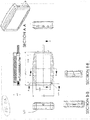
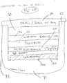
- FIGS. 13A-13B illustrate aspects of one embodiment of housing 40 suitable for use with portable ultrasound system 10.
- housing 40 can include two component halves that fit together to form a chamber suitable to house the energy generating module.
- One or more of the two component halves can include ports for a cable (e.g., to the ultrasound transducer), indicator light (e.g., indicating on/off), and an on/off switch (e.g., a toggle switch).
- a cable e.g., to the ultrasound transducer
- indicator light e.g., indicating on/off
- an on/off switch e.g., a toggle switch
- Portable ultrasound system 10 can be assembled so that energy generating module 20 is at least partially housed on or within ultrasound transducer 30.
- oscillator 22 and driver component 23 are housed on or within ultrasound transducer 30, and power source 21 is housed in housing 40, with cable 51 operatively coupling power source 21 to oscillator 22/driver component 23 (housed on or within ultrasound transducer 30).
- energy generating module 20 can further include voltage controller 24 operative to control power distribution from power source 21 to oscillator 22/driver component 23.
- voltage controller 24 can either be housed in housing 40 along with power source 21 or housed on or within ultrasound transducer 30.
- voltage controller 24 can include on/off controller 24a coupled to transistor switch 24b.
- Portable ultrasound system 10 can also be assembled so that energy generating module 20 is completely housed on or within ultrasound transducer 30.
- a suitable transducer can include, without limitation, the low-profile ultrasound transducer of the present invention.
- the portable ultrasound system is well suited for use with ultrasound transducers that are configured as low-profile type of ultrasound transducers.
- low-profile ultrasound transducer is meant to include any ultrasound transducer that is configured to have a profile not greater than about 6 centimeters in height.
- the portable ultrasound system is also well suited for use with coupling devices designed for low-profile ultrasound transducers.
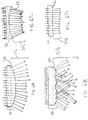
- FIGS. 14 , 15A-15B , 16A , 16B , 17 , 18 , 19 , 20 , 21 , and 22 provide illustrative examples of suitable low-profile ultrasound transducers 50, or aspects thereof that can be used with portable ultrasound system 10.
- Suitable ultrasound coupling devices 100 that can be used with portable ultrasound system 10 and low-profile ultrasound transducers 50 are contemplated to include any device that holds the system or transducer in place on any region of a subject, whether a human or animal subject.
- the present invention relates to a low-profile ultrasound transducer suitable for use with ultrasound systems, particularly portable ultrasound systems.
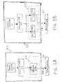
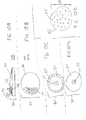
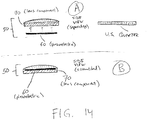
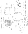
- FIGS. 14A-14B provide schematics of one embodiment of the low-profile ultrasound transducer.
- low-profile ultrasound transducer 50 includes piezoelectric component 60 and lens component 70.
- FIGS. 14A-14B show ultrasound transducer 50 having lens component 70 that houses piezoelectric component 60 and that is configured as a single unit.
- FIG. 14A shows the various components prior to assembly.
- piezoelectric component is a wafer disc about the size of a United States quarter dollar coin.
- FIG. 14B shows low-profile ultrasound transducer 50 fully assembled.
- Piezoelectric component 60 is operative to receive a driving signal from energy generating module 20 and to emit the driving signal as ultrasonic energy 35.
- Piezoelectric component 60 is generally shaped as a disc having front surface 61 and back surface 62.
- Piezoelectric component 60 is operative with an energy generating module 20 having a plurality of electronic components 26.
- the plurality of electronic components 26 of energy generating module 20 includes power source 21, oscillator 22, and driver component 23.
- the plurality of electronic components 26 of energy generating module 20 can further include temperature sensor 25 and/or wireless recharger component 90.
- Other suitable electronic components useful in ultrasound circuitry are contemplated by the present invention.
- Piezoelectric component 60 is effective to transmit ultrasonic energy having an acoustic intensity ranging from between about 10 mW/cm 2 and about 5 W/cm 2 .
- lens component 70 includes lens portion 71 and support portion 72.
- Lens component 70 can be directly or indirectly deposited on front surface 61 of piezoelectric component 60.
- Lens portion 71 of lens component 70 is configured to control the direction and wave pattern of ultrasonic energy 35 emitted from piezoelectric component 60.
- Support portion 72 of lens component 70 is also configured to hold piezoelectric component 60 in place and to provide chamber 73 for housing at least one electronic component 26 of energy generating module 20.
- lens portion 72 can be configured to emit ultrasonic energy 35 in various wave patterns, including, for example, diverging wave pattern 35a, scattering wave pattern 35b, focused wave pattern 35c, or parallel wave pattern 35d.
- lens portion 71 can be convex lens 74 configured to emit the ultrasonic energy in diverging wave pattern 35a.
- lens portion 71 can be ridged lens 75 configured to emit the ultrasonic energy in scattering wave pattern 35b.
- the lens may be used to direct energy into joints where the transducer may not be easily positioned over.
- the lens can be used to control the distribution of ultrasound energy.
- the lens can be used to form ultrasound standing waves in the body.
- the lens can also be used to prevent standing wave formation in the body.
- the lens can be used to generate random acoustic field patterns.
- Lens component 70 is effective to spread ultrasonic energy emitted from piezoelectric component 60 for ultrasound therapy from an angle ranging from between about 0 degrees and about 180 degrees.
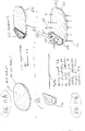
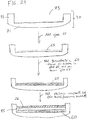
- support portion 72 is configured as a ring 80 having outer ring portion 81 and inner ring portion 82, with inner ring portion 82 forming a ring-like shelf within outer ring portion 81 effective to hold piezoelectric component 60 in place.
- lens portion 71 and support portion 72 form a single lens component 70.
- lens portion 71 forms a front end base portion 71a of chamber 73
- support portion 72 forms support wall 83 of chamber 73.
- support wall 83 extends in a backward direction from front end base portion 71a.
- Support portion 72 can further include opening 72a, which can be used as a passage way for a cable that connects the piezoelectric component or other electronic component to another electronic component disposed outside of chamber 73 (e.g., a power source connected by a cable).
- one embodiment of lens component 70 can be configured to include notches 72b as part of the inner surface of support wall 83. Notches 72b function to position piezoelectric component 60 within chamber 73 in a manner well-suited for attaching piezoelectric component 60 to front end base portion 71a of chamber 73.
- three notches 72b can be included as part of the inner surface of support wall 83.
- glue or another suitable adhesive is used to secure piezoelectric component 60 in place on front end base portion 71a.
- piezoelectric component 60 is then placed within chamber 73 so that it comes in contact with front end base portion 71a, with the glue layer being disposed between piezoelectric component 60 and front end base portion 71a.
- Notches 72b position piezoelectric component 60 so that there is space between the outer edges of piezoelectric component and the inner surface of support wall 83.
- FIG. 17 shows an embodiment having three notches 72b, the present invention is not limited to three notches 72b, but includes embodiments having other arrangements, as long as an adequate space for exuding excess glue and air bubbles is provided.
- support wall 83 can be configured to include wireless recharger coil 90a.
- Suitable wireless recharger coils 90a can include, without limitation, wire rings, inductive coupling, and the like.
- Wireless recharger coils 90a are used in embodiments that use rechargeable batteries.
- the coil in the wall maximizes the inductive-charging capability because it allows for the electrical field pass through the center of the coil.
- the coil in the wall also maintains the low profile of the device.
- the coil does not have to be in the housing wall.
- the coil could be in the inside of the transducer, in the case of the system or on the outside of the transducer in the coupling device (e.g., a rubber boot), in the coupling device (e.g., rubber boot), or in-between the case and the rubber boot.
- low-profile ultrasound transducer 50 can be configured to also include cover 84.
- Cover 84 is deposited over support wall 83 in a manner effective to substantially close chamber 73. This embodiment is useful to protect any electronic components 26 contained within chamber 73.
- chamber 73 can house piezoelectric component 60 in addition to at least one electronic component 26 of energy generating module 20.
- Electronic components 26 housed in chamber 73 can include one or more of the following: power source 21, oscillator 22, driver component 23, temperature sensor 25, and wireless recharger component 90.
- the one or more electronic components 26 are housed in chamber 73 so as to be separated from piezoelectric component 60 by layer of air 85.
- This can be achieved using various techniques know in the electronics field. Examples of such techniques can include air backing or vacuum backing techniques known in the art.
- the piezoelectric component is air backed or vacuum backed to increase ultrasonic energy propagation in a forward direction.
- At least one electronic component can be either mounted onto the piezoelectric component or deposited near but not onto the piezoelectric component.
- temperature sensor 25 is well suited for being the only electronic component to be mounted onto piezoelectric component 60 or deposited near but not onto piezoelectric component 60.
- Temperature sensor 25 is useful in detecting the heat level and in trigger a shutdown of power when the heat level rises to a predetermined level. Suitable temperature sensors can include, for example, thermal cutoffs, remote temp sensing ICs, and local temp sensing ICs.
- Another aspect of the low-profile ultrasound transducer relates to the use of the transducer in both generating ultrasonic energy and light energy.
- These embodiments of the low-profile ultrasound transducer include at least one light source operative to generate light energy from the driving signal provided by the energy generating module.
- the light source can be wired to a front conductor of the piezoelectric component and a back conductor of the piezoelectric component, thereby allowing the driving signal to the piezoelectric component to power the light source.
- the light source can be wired around the piezoelectric component or through the piezoelectric component.
- the light source can be configured to be powered either in series or in parallel with the piezoelectric component.
- the light source can be generated either from the piezo generator or from a separate external generator.
- low-profile ultrasound transducer 50 can be configured to include light source 52 or a plurality of light sources 52 securely deposited in proximity to piezoelectric component 60 and/or lens component 70.
- Suitable light sources can include any light source that can run on the power source.
- the light source can be a light-emitting diode (LED), a laser, or a combination thereof.
- lens component 70 can be configured to be operative to allow light energy 52a to pass through it. As shown, light energy 52a is emitted through lens component 70 through front surface 61 of piezoelectric component 60.
- light source 52 can be configured to be set inside of lens component 70, inside piezoelectric component 60, or inside both lens component 70 and piezoelectric component 60.
- light source 52 can be configured to be set substantially in the center of lens component 70, piezoelectric component 60, or both lens component 70 and piezoelectric component 60.
- the low-profile ultrasound transducer of the present invention can be integrated into a portable ultrasound system, including portable ultrasound systems that include an energy generating module, where the energy generating module includes a power source, an oscillator, and a driver component coupled to the transducer.
- the energy generating module can either be housed within or not housed within the low-profile ultrasound transducer.
- the present invention also relates to a multi-unit transducer that includes a plurality of the ultrasound transducers combined into a single multi-unit transducer, with at least one of the transducers being a low-profile transducer described herein.
- the plurality of ultrasound transducers can include transducers of either the same or different functions and/or sizes, and can emit the same or different intensity, duration, or frequency of ultrasonic energy or light energy.
- the low-profile ultrasound transducer of the present invention can be made as follows: (i) providing a piezoelectric component operative to receive a driving signal from an energy generating module and to emit the driving signal as ultrasonic energy, said piezoelectric component having a front surface and a back surface, and said energy generating module comprising a plurality of electronic components; (ii) providing a lens component said lens component comprising a lens portion and a support portion; and (iii) directly or indirectly depositing the lens component on the front surface of the piezoelectric component, wherein the lens portion of the lens component is configured to control the direction and wave pattern of the ultrasonic energy emitted from the piezoelectric component, and wherein the support portion of the lens component is configured to hold the piezoelectric component in place and to provide a chamber for housing at least one electronic component of the energy generating module.
- the lens and housing are combined into one piece so that the piezoelectric is dropped in and glued into place.
- a heat sensor can be soldered to the back of the piezoelectric.
- the casing backplate can then be glued to seal the air backed portion of the piezoelectric.
- the circuitry and power source can also be placed into the transducer housing.
- ASIC Application Specific Integrated Circuit
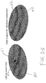
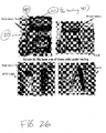
- FIG. 26 is a photograph showing various embodiments of the ultrasound transducer of the present invention.
- Various well known objects e.g., a United States quarter dollar coin, a pack of playing cards, and an Apple iPOD Nano
- FIG. 26 is also provided in FIG. 26 in order to illustrate the relative size of the depicted portable ultrasound system/low-profile ultrasound transducer of the present invention.
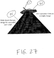
- the low-profile ultrasound transducer and the ultrasound system of the present invention are operative in producing a wide range of ultrasonic beams and wave patterns, enabling a wide range of applications.
- a particular embodiment produces ultrasonic energy 35 in the form of a wide-beam that can be used for extended pain relief.
- the ultrasound system can operate for 8 hours on a single charge.
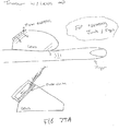
- FIGS. 28A , 28B , and 28C the low-profile ultrasound transducer and the ultrasound system of the present invention can be used for a number of applications.
- FIG. 28A shows the use of the system and transducer for treating joints of the fingers.
- the lens can be configured to direct the ultrasonic energy to the area of interest on and within the tissue of the subject near and at the joint.
- FIG. 28B shows the use of the system and transducer for treating the arm of a subject.
- a hydrogel component can be used in tandem with the transducer as an ultrasound conductive medium.
- the hydrogel component can be configured to fit the shape of the transducer and lens in order to couple ultrasonic energy into the body (e.g., into the arm tissue) of a subject.
- FIG. 28C shows the use of multiple systems in an array.
- a plurality of ultrasound transducers/systems of the present invention can be coupled with a holder component 900 (shown as a multi-unit holder component 902).
- holder component 900 can be in the form of a Neoprene wrap and used to treat a large area such as the lower back (as shown).
- the basic use involves applying ultrasonic energy to a subject, whether human or animal, at a target area using the portable ultrasound system and/or the low-profile ultrasound transducer of the present invention.
- the length of time and intensity can be based on industry standards. Some uses can be found at www.ultroz.com. Below is a brief description of certain uses of the portable ultrasound system and the low-profile ultrasound transducer of the present invention.
- a method for performing physiotherapy on a subject involves providing a portable ultrasound system of the present invention or a plurality of the systems in the form of an array, and then applying therapeutic ultrasound energy to a target area of a subject, where the therapeutic ultrasound energy is generated by the system or array of systems.
- a method for applying ultrasound energy to a subject involves providing a portable ultrasound system of the present invention or a plurality of the systems in the form of an array, and applying ultrasound energy to a target surface of a subject, where the ultrasound energy is generated by the system or array of systems.
- a method of topically delivering a drug to a subject involves providing a portable ultrasound system of the present invention or a plurality of the systems in the form of an array, where the deliverable component includes a drug to be delivered to a subject, and applying ultrasound energy to a surface of a subject along with the deliverable component, where the ultrasound energy is generated by the system or array of systems.
- a method of internally delivering a drug to a subject involves administering to a subject a biocompatible device of the present invention, where the biocompatible component is in the form of an ingestible device that includes a drug to be delivered to the subject, and where the device is effective to generate ultrasound energy in order to facilitate internal delivery of the drug to the subject.
- the portable ultrasound system and low-profile ultrasound transducer of the present invention have various attributes, as described herein and as further discussed below.
- the ultrasound power source and circuit are such that they can be mounted directly onto the ultrasound transducer (e.g., the piezoelectric component).
- the complete ultrasound system of the present invention can be as small as a stack of approximately 2-3 U.S. quarters.
- the ultrasound producing circuit used in the system of the present invention can include two components: (i) an oscillator to control the frequency of the device; and (ii) two pin drivers in parallel to drive the transducer, although as few as one pin driver could be used.
- Another optional component of the ultrasound system of the present invention can be a light-emitting diode (LED) or a plurality of LEDs, which may be arranged around the ultrasound transducer to provide "light" therapy.
- the LEDs can be powered from the same ultrasound producing circuit that powers the ultrasound transducer.
- the power source used to power the device may be any source of power suitable for generating the necessary power to run the ultrasound system according to its intended use.
- a particular suitable power source that can be used to power the device may include, without limitation, batteries such as coin lithium ion watch batteries and the like.
- one embodiment of the ultrasound producing system of the present invention can include a piezoelectric, ultrasound generating circuit, and power supply. Additional features may include power control (On/Off), LED's, lenses, and recharging capability.
- power control On/Off
- LED's LED's
- lenses lenses
- recharging capability One advantageous aspect of this invention is that the complete ultrasound device may be made in the size and shape of a U.S. quarter or even smaller (e.g., an ingestible pill).
- the portable ultrasound system has various attributes, including, for example, the following: (i) it is low profile; (ii) it uses a flat or concave piezoelectric material (which may be of any diameter); (iii) the piezoelectric is connected directly to the ultrasound circuit; (iv) the housing of the system is made from ultrasound transducer (and/or lens) on the front side; (v) on the back side the ultrasound generating circuit is in a low-profile housing; (vi) the transducer is driven at resonance so it has low impedance for efficient energy transfer; and (vii) the system is lightweight, efficient, and water tight.
- the small size of the ultrasound system of the present invention can enable numerous uses and applications that have not been possible or practicable thus far.
- the low profile ultrasound system of the present invention may be used in implantable devices and ingestible devices (e.g., smart pills).
- the ultrasound system of the present invention may be used for physiotherapy, drug delivery, pain management and therapy, and the like.
- the ultrasound system of the present invention may also be used virtually for any place one may want to apply ultrasound to at frequencies from 0-40 MHz.
- the internal batteries of the ultrasound system of the present invention may be supplemented with external batteries to provided extended use in various scenarios.
- the system may be recharged.
- the system may be operated by an external device.
- the device may also be coated with a drug or bio-compatible material to improve incorporation into the body.
- the Transducer can be a 1.91-2.54 cm (0.75-1.0 inch) diameter and 2-3 MHz ultrasound generator with transducer, along with ultra efficient ultrasound generation technology built right into it.
- the entire transducer and electronics can be approximately the size of three quarters (or less) stacked on top of each other.
- the transducer can incorporate wide-beam technology to spread ultrasound therapy deep into tissues and over an extensive range.
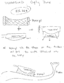
- the Ultrasound Conductive Patch The ultrasound system of the present invention can be used in tandem with an ultrasound conductive patch.
- Suitable patches can include, without limitation, a disposable one-time use patch for efficiently coupling ultrasound energy into tissues during activity.
- the patch can include ultrasound gel built into it, enabling the user to insert the transducer into the device, peel off the sticky bandage, and apply it to the appropriate location on the skin.
- the pain patch can be made from ultra flexible material.
- the Ultrasound Power Module The ultrasound system of the present invention can also be used in tandem with an ultrasound power module that is a light weight rectangular lithium-ion rechargeable battery pack with user interfaced pain power settings.
- the power module may provide low 60 mW/cm 2 or high 100 mW/cm 2 intensity of sustained therapeutic 2-3 MHz ultrasound for 6-8 hrs.
- the recharge time for the power module can be 1 hr after full discharge of the unit.
- the Complete System enables ultrasound therapy that is portable and in many cases unnoticeable. With the wide-beam transducer and efficient power technology the device may be used on the road, at the office, before, during, and after a sporting activity or event, and in many other situations.
- the ultrasound system of the present invention may also be suitable for use by amateur, grade school, collegiate, semi-professional, and professional athletes and sports teams.
- the ultrasound system of the present invention is suitable for use in spas, athletic training rooms, locker rooms, physical therapy offices, physicians offices, on the sidelines of sporting events, at home, and the like.
- an implantable device for use in generating ultrasound energy within a patient.
- the device includes the ultrasound system and an implantable component configured to contain the ultrasound system.
- an ingestible device for use in generating ultrasound energy within a patient.
- the device includes the system of the present invention and an ingestible component configured to contain the system.
- a suitable ingestible component can be, without limitation, in the form of a pill
- a method for performing physiotherapy on a subject involves providing the ultrasound system of the present invention and applying therapeutic ultrasound energy to a subject, where the therapeutic ultrasound energy is generated by the system of the present invention.
- the ultrasound energy emitted by the system is effective to penetrate deep into the tissue of the subject, and is not limited to just providing surface ultrasound energy.
- a method for applying ultrasound energy to a subject involves providing the ultrasound system of the present invention and applying ultrasound energy to a surface of a subject, where the ultrasound energy is generated by the system of the present invention.
- the ultrasound energy emitted by the system is effective to penetrate deep into the tissue of the subject, and is not limited to just providing surface ultrasound energy.
- applying the ultrasound energy to the surface of the subject can be effective to alleviate pain in tissue of the subject in and around the surface.
- a method of topically delivering a drug to a subject involves providing the ultrasound system of the present invention, where the system also includes a reservoir mounted to the piezoelectric component, the reservoir being configured to store a deliverable component in the absence of ultrasound energy generation and to release the deliverable component in the presence of ultrasound energy generation.
- the deliverable component comprises a drug to be delivered to a subject.
- ultrasound energy is applied to a surface of a subject along with the deliverable component, where the ultrasound energy is generated by the system of the present invention.
- the ultrasound energy emitted by the system is effective to penetrate deep into the tissue of the subject, and is not limited to just providing surface ultrasound energy.
- a method of internally delivering a drug to a subject involves administering to a subject an ingestible device of the present invention, where the ingestible component is in the form of a pill that comprises a drug to be delivered to the subject, and where the system is effective to generate ultrasound energy in order to facilitate internal delivery of the drug to the subject.
- Ultrasound is currently used in many medical diagnostic applications across the globe such as imaging, fetal heart rate monitoring, and blood flow analysis. Ultrasound is also present in various non-diagnostic drug delivery and therapeutic applications. The mechanical and thermal mechanisms of action in ultrasound have been shown to facilitate wound and bone fracture healing, enhance the penetration of topical ointments into the skin, provide pain and healing relief in physiotherapy, and perform non-invasive tumor and fibroid ablation.
- TheraSonXTM is the first truly portable Low Intensity Ultrasound (LIUS) device which can provide safe, effective relief outside of the hospital.
- LIUS Low Intensity Ultrasound
- TheraSonXTM corresponds to one embodiment of the portable ultrasound system of the present invention that incorporates one embodiment of the low-profile ultrasound transducer of the present invention.
- the primary safety concern with ultrasound is the direct effect of ultrasonic energy on tissue.
- the ability of ultrasound to induce tissue effects has been quantified through two parameters: the thermal index and the mechanical index.
- the FDA has set upper limits on these indices for safety of diagnostic ultrasound. Extension of these limits for therapeutic applications are based on the long term studies conducted by independent research organizations and the AIUM. To date, no peer reviewed published study has shown a negative impact from properly administered ultrasound use on human subjects. This is significant given the 50 year history of ultrasound use in both diagnostic and therapeutic applications. More specifically to the TheraSonXTM range of operation, a study was conducted on low intensity ultrasound delivered over multiple days of continuous application. The study definitively showed that no adverse biological tissue effects were seen on tissue receiving 100mW/cm 2 or less ultrasound intensity for over 10 consecutive days ( FIG. 29 ) [1-3]. Given this information, the 4 hour TheraSonXTM treatments at an 80 mW/cm 2 intensity present a non-significant risk to subjects involved in clinical study.
- TheraSonXTM transducer TheraSonXTM is made from a lead based piezoelectric ceramic that is typical of most therapeutic ultrasound systems. To protect the clinical trial subject and the piezoelectric, the piezoelectric is completely housed in a waterproof biocompatible shell consisting of the lens, ring housing, and boot. The wire that extends from the transducer is RoHS compliant and coated in Polyvinyl Chloride (PVC). The lens and housing is made from a cross linked polystyrene. Finally, the rubber boot is made from 55A and 80A durometer polyurethanes.
- MSDS Material Safety Data Sheets
- the electronic circuit uses 100% RoHS compliant components as well as printed circuit board fabrication process that are standard practice in consumer and medical electronic devices.
- the battery and housing also maintain RoHS certification.
- Appendix 1 lists general part numbers and manufactures for the electronics, battery and housing.
- TheraSonXTM system is a medical device used to treat pain and improve quality of life for subjects.
- the system produces safe levels of ultrasound that have been found harmless and approved by regulatory bodies such as the FDA. Nevertheless, ultrasound is a form of energy and must be monitored and delivered appropriately to prevent possible danger to the subject. Risk is mitigated by complying with regulatory standards, maintaining good manufacturing processes, maintaining design history files, and performing failure modes and effects analysis.
- the total acoustic power and intensity from TheraSonXTM is measured during calibration procedures. Both power and intensity are directly proportional and are a function of battery voltage, transducer impedance, and frequency of operation. From a theoretical standpoint, the electrical impedance of a 25 mm diameter PZT-8 piezoelectric is approximately 12 ohms. If the piezoelectric could convert electrical energy into acoustic energy 100% efficiently, the ultrasonic power (P) in Watts would be calculated by:
- the drive voltage from TheraSonXTM is a maximum RMS value of 4/sqrt(2) volts only allowing 0.67 W of acoustic energy to possibly be generated. Since the transducer is not 100% efficient we generally measure a total acoustic power of less than 0.5 watts. The total acoustic power is spread over the entire surface area of the transducer, thereby bringing the intensity of ultrasound treatment below the safe 100mW/cm 2 threshold.
- Ultrasonic temperature analysis shows that continuous ultrasound application below 0.5 W/cm 2 results in safe temperature increases of 1-4°C [1-3]. A subject could wear this device for many days with no thermal bio-safety concerns. This study suggests an intensity safety threshold even higher than the 0.1 W/cm 2 guidance from the American Institute of Ultrasound in Medicine (AIUM).
- AIUM American Institute of Ultrasound in Medicine
- TheraSonXTM operates within established FDA parameters for safe use over a continuous timeframe.
- Table 2-1 Pre-amendments Acoustic Output Exposure Levels (mW/cm 2 ) Use
- I SPTA I SPPA or MI
- Peripheral Vessel 720 190 or 1.9 Cardiac 430 190 or 1.9 Fetal Imaging 94 190 or 0.28 Ophthalmic 17 28 or 0.23
- I STPA Derated Spatial-Peak Temporal-Average Intensity
- FIG. 29 summarizes the AIUM guidelines [1-3]:
- Power output from the TheraSonXTM device is preset at a low intensity (80-90mW/cm 2 ) and cannot be modified by the user.
- TheraSonXTM device Another measure of safety is to compare the TheraSonXTM device to already FDA approved ultrasound devices on the market today.
- the following device has already been approved by the FDA for extended Low Intensity Ultrasound (LIUS) treatments: NanoVibronix "Painshield” - FDA 510(k) (K081075) approved in June, 2008 to apply ultrasonic energy to generate heat within body tissues for the treatment of selected medical conditions such as relief of pain, muscle spasms, and joint contractures. More data for predicate devices can be found in the Regulatory Path Details section of this compilation.
- LIUS Low Intensity Ultrasound
- MI is a standard measure of the acoustic output in ultrasound systems defined as the peak rarefactional pressure of an ultrasound longitudinal wave propagating in a uniform medium, divided by the square root of the center frequency of the transmitted ultrasound wave. According to the FDA for diagnostic obstetrics application, the MI should not exceed 1.9.
- we will use the intensity (I) and acoustic impedance of muscle tissue (Z 1.6e6 kg/m 2 s) in order to calculate the pressure (P) and derived the following formula for TheraSonXTM to calculate a MI of 0.023 according to:
- T thermal Index
- I ultrasound intensity
- A transducer area
- the calculated MI is less than 1.9 and the T s value achieved is less than 6 for TheraSonXTM.
- the system is therefore safe according to established FDA guidelines. It should also be noted that the calculated MI and TI for TheraSonXTM slowly decrease as the system losses battery charge and that it is physically impossible (due to battery voltage and electrical restrictions) for the system to produce levels of ultrasound that would cause mechanical or thermal damage to the tissue.
- Improper placement of the device directly over a bone may significantly reduce the effectiveness of the device. If the transducer is placed in such a manner that it does not make solid contact with the skin (for instance placed over a small bone which resides directly under the skin's surface eg. tip of an elbow), then ultrasound waves may not be efficiently transferred through the skin.
- TheraSonXTM intensity 80-90mW/cm 2
- TheraSonXTM intensity 80-90mW/cm 2
- TheraSonXTM would not be a safety issue because A) it will run out of battery power (maximum 6 hrs) and stop emitting ultrasound altogether, B) if the device was plugged into the recharger during use, it would be safe for 10 consecutive days, C) the bandages used to hold the transducer in place are biocompatible for extensive use periods (greater than 48 consecutive hours).
- the battery box will become warm during recharging, but remains within safe thermal limits due to intelligent charging built into TheraSonXTM.
- Internal circuitry monitors the recharging process and any change in voltage, current, or thermal temperature outside of specified limits will result in a shutdown. Additionally, since the battery box is not attached to the body directly, it does not represent a threat to the subject.
- the battery box is water resistant and may be used in humid and damp environments but is not water proof (similar to a cell phone). If the battery box is submerged in water by accident, the electronics and battery may become damaged, however there is minimal risk for painful or life threatening shock since the device operates at less than 4 Volt power level. We mitigate the risk to subjects for potential shock by encasing electrodes, wires, circuits and all of the electronic components in additional non-conductive material, before it is enclosed in the battery box housing.
- the charger supplies a 4.2 Volt isolated recharge power with internal short circuit detection to prevent electrical shock.
- Change in Gait-Placement of the non-invasive device is accomplished using a flexible patch that does not restrict the subject's movement or cause additional risk to the subject.
- the wire between the battery and transducer does not wrap around or otherwise hinder the movement during normal use.
- the wire is kept short to prevent risk of tripping or "snagging" on objects during movement.
- the transducer and wiring When wearing clothing the transducer and wiring will be concealed beneath the clothing and the battery housing will be secured by belt clip case or in the pocket, further reducing risk of snagging or tripping.
- Subjects involved in the clinical trial will receive an orientation and directions for appropriate use prior to receiving a device for treatment. Subjects will be instructed to:
- Acoustic power and intensity measurements-Acoustic power is measured using a calibrated acoustic power meter from Ohmic Instruments (www.ohmicinstruments.com) with 2 mW ultrasound power resolution.
- the TheraSonXTM transducer is placed in a power meter filled with degassed water, the meter is zeroed, and the TheraSonXTM unit is turned on.
- the ultrasound energy radiated from transducer causes a force that is detected on a power meter calibrated in acoustic watts (W).
- the power meter is connected to a computer via USB to log measurement data from TheraSonXTM every 2 minutes until the battery of the device is completely diminished and the system turns off.
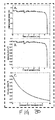
- TheraSonXTM system produces a total acoustic output power of 440-460 mW at full system charge and slowly decreases over the charge cycle of the device to a steady state 380-400 mW of acoustic power (shown in FIG. 30A from TheraSonXTM units measured in lab).
- the spatial average acoustic intensity is calculated by a mathematical calculation: dividing the total acoustic power, by the surface area of the transducer.
- the output intensity of TheraSonXTM is shown in FIG. 30B for over 6 hrs.
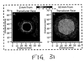
- Peak spatial and temporal ultrasound intensity is measure using a beam scanning system in conjunction with a calibrated hydrophone (www.onda.com).
- the beam scanning system is also used to characterize the width of the ultrasound acoustic field during development of the transducer lenses.
- FIG. 31A shows the measured acoustic intensity field from the TheraSonXTM transducer with 10° lens 2 mm (A) and 60 mm (B) from the face of the transducer.
- SR Significant Risk
- NSR Non-Significant Risk
- the system under evaluation is completely non-invasive and will never be implanted during the course of treatment.
- the system is not used to sustain life and is not a critical element in diagnosing or treating any life threatening condition. According to guidance released by the FDA (table 2-1) and studies performed by the American Institute of Ultrasound in Medicine ( Figure 1 ), the system under evaluation does not present a potential for serious risk to the health, safety, or welfare of the subject.
- the FDA was contacted via phone to provide guidance related to the safe evaluation of TheraSonXTM in clinical testing prior to FDA approval.
- Phone conversations with the FDA Office of Device Exemption validated the NSR intensity levels referenced in Table 2-1. These are threshold levels of intensity that determine whether a change (by the manufacturer) in a diagnostic Ultrasound device's output warrants a new FDA safety review. If the change in intensity is below the thresholds in Table 2-1, NO amendment is necessary because the change in observed in bio-effects is zero or near zero.
- Subject was a 2 yr old thoroughbred filly. The filly had been in race training on a farm and was moving up to the next level of training by coming to the Churchill Downs race track.
- the filly arrived at the track with a large splint on the right front leg, medial aspect.
- the filly was not lame on arrival or through the days of UltrOZ ultrasound treatment.
- the UltrOZ unit was applied to the caudal aspect of the splint, covering the suspensory ligament as well. It was applied from 10 a.m. to 3 p.m. every day, 7 days a week from 10/22 to 11/20. No other treatments were performed.
- Horse Subject 9 year old, thoroughbred, gelding. Mid level event horse.
- a new splint had formed on the proximal aspect of the 4th metacarpal bone of the right fore.
- the horse blocked to regional local anesthesia of the splint and suspensory ligament.
- Radiographs revealed no fracture but active periosteal proliferation of the splint.
- Ultrasound of the suspensory ligament showed mild inflammation at the region associated with the splint.
- the horse was treated with the anti-inflammatory Equioxx for 10 days.
- a regional injection at the splint/suspensory interface of betamethasone/serapin/predef was done.
- the horse was stall rested for 7 days, stalled and tack walked for 7 days. Small paddock with tack walk for remainder of 30 days.
- a prototype Zetroz therapeutic ultrasound unit was utilized beginning 2 days after the initial injection for 3 weeks. The unit was used under a standing bandage to hold in place. The unit stayed in place for overnight treatment every day for 3 weeks with no difficulties.
- the horse was 40% improved at 7 days, 100% sound at 2 weeks.
- the splint reduced in size 50% by week 3.
- the speed of return to soundness and the rapid reduction in the size of the splint were the atypical components of the outcome compared to the normal case.
- the horse has remained sound back into work 6 weeks later.
Landscapes
- Health & Medical Sciences (AREA)
- Life Sciences & Earth Sciences (AREA)
- Engineering & Computer Science (AREA)
- Biomedical Technology (AREA)
- Nuclear Medicine, Radiotherapy & Molecular Imaging (AREA)
- Radiology & Medical Imaging (AREA)
- Animal Behavior & Ethology (AREA)
- General Health & Medical Sciences (AREA)
- Public Health (AREA)
- Veterinary Medicine (AREA)
- Physics & Mathematics (AREA)
- Pathology (AREA)
- Biophysics (AREA)
- Heart & Thoracic Surgery (AREA)
- Medical Informatics (AREA)
- Molecular Biology (AREA)
- Surgery (AREA)
- Acoustics & Sound (AREA)
- Surgical Instruments (AREA)
- Transducers For Ultrasonic Waves (AREA)
- Percussion Or Vibration Massage (AREA)
- Apparatuses For Generation Of Mechanical Vibrations (AREA)
- Ultra Sonic Daignosis Equipment (AREA)
- Electrotherapy Devices (AREA)
Claims (27)
- Niedrigprofilultraschallwandler (10), umfassend:eine piezoelektrische Komponente (60), die betriebsfähig ist, um ein Treibsignal von einem Energieerzeugungsmodul (20) zu empfangen und das Treibsignal als Ultraschallenergie zu emittieren, wobei die piezoelektrische Komponente (60) eine vordere Oberfläche (61) und eine hintere Oberfläche (62) aufweist, und wobei das Energieerzeugungsmodul (20) mehrere elektronische Komponenten umfasst, die eine Stromquelle (21), einen Oszillator (22) und eine Treiberkomponente (23) umfassen; undeine Linsenkomponente (70), die auf der vorderen Oberfläche (61) der piezoelektrischen Komponente (60) direkt oder indirekt angebracht ist, wobei die Linsenkomponente (70) einen Linsenabschnitt (71) und einen Stützabschnitt (72) umfasst,wobei der Linsenabschnitt (71) der Linsenkomponente (70) konfiguriert ist, um die Richtung und das Wellenmuster der Ultraschallenergie zu steuern, die von der piezoelektrischen Komponente (60) emittiert wird, undwobei der Stützabschnitt (72) der Linsenkomponente (70) konfiguriert ist, um die piezoelektrische Komponente (60) an Ort und Stelle zu halten und um eine Kammer (73) zum Aufnehmen mindestens einer elektronischen Komponente des Energieerzeugungsmoduls (20) bereitzustellen, dadurch gekennzeichnet, dassdie mindestens eine elektronische Komponente die Stromquelle (21), der Oszillator (22) und/oder die Treiberkomponente (23) ist.
- Wandler nach Anspruch 1, wobei die mehreren elektronischen Komponenten des Energieerzeugungsmoduls ferner eine elektronische Komponente umfassen, die entweder einen Temperatursensor (25) oder eine drahtlose Aufladekomponente (90) umfasst.
- Wandler nach Anspruch 1, wobei die piezoelektrische Komponente (60) wirksam ist, um Ultraschallenergie zu übertragen, die eine Schallintensität aufweist, die von zwischen etwa 10 mW/cm2 und etwa 5 W/cm2 reicht.
- Wandler nach Anspruch 1, wobei der Linsenabschnitt (71) konfiguriert ist, um Ultraschallenergie in einem Wellenmuster zu emittieren, das aus der Gruppe ausgewählt ist, die aus einem divergierenden Wellenmuster, einem streuenden Wellenmuster, einem fokussierten Wellenmuster, einem parallelen Wellenmuster und einem gerichteten Wellenmuster in einem beliebigen Winkel von 1 bis 180 Grad von einer Oberfläche besteht.
- Wandler nach Anspruch 1, wobei der Linsenabschnitt (71) eine konvexe Linse (74) oder eine kantige Linse (75) umfasst, wobei die konvexe Linse konfiguriert ist, um die Ultraschallenergie in einem divergierenden Wellenmuster zu emittieren und die kantige Linse konfiguriert ist, um die Ultraschallenergie in einem streuenden Wellenmuster zu emittieren.
- Wandler nach Anspruch 1, wobei die Linsenkomponente (70) die Ultraschallenergie, die von der piezoelektrischen Komponente (60) emittiert wird, für eine Ultraschalltherapie aus einem Winkel verteilt, der von zwischen etwa 0 Grad und etwa 180 Grad reicht.
- Wandler nach Anspruch 1, wobei der Stützabschnitt (72) als ein Ring (80) konfiguriert ist, der einen Außenringabschnitt (81) und einen Innenringabschnitt (82) aufweist, wobei der Innenring (82) eine ringartige Ablage innerhalb des Außenrings (81) ausbildet, die wirksam ist, um die piezoelektrische Komponente (60) an Ort und Stelle zu halten.
- Wandler nach Anspruch 1, wobei der Linsenabschnitt (71) und der Stützabschnitt (72) eine einzige Linsenkomponente ausbilden, wobei der Linsenabschnitt (71) einen vorderen Endbasisabschnitt (71a) der Kammer (73) ausbildet und der Stützabschnitt (72) eine Stützwand (83) der Kammer (73) ausbildet, wobei sich die Stützwand (72) von dem vorderen Endbasisabschnitt (71a) in einer Rückwärtsrichtung erstreckt.
- Wandler nach Anspruch 8, wobei die Stützwand (72) eine drahtlose Aufladespule (90a) enthält.
- Wandler nach Anspruch 8, ferner umfassend:
eine Abdeckung (84), die über der Stützwand (83) angebracht ist, um die Kammer (73) zu verschließen. - Wandler nach Anspruch 8, wobei die mindestens eine elektronische Komponente des Energieerzeugungsmoduls (20), das in der Kammer (73) aufgenommen ist, eine oder mehrere elektronische Komponenten beinhaltet, die aus der Gruppe ausgewählt sind, die aus einer Stromquelle, einem Oszillator, einer Treiberkomponente, einem Temperatursensor und einer drahtlosen Aufladekomponente besteht.
- Wandler nach Anspruch 8, wobei die mindestens eine elektronische Komponente durch eine Luftschicht von der piezoelektrischen Komponente (60) getrennt ist.
- Wandler nach Anspruch 8, wobei die mindestens eine elektronische Komponente ein Temperatursensor ist, der entweder auf die piezoelektrischen Komponente (60) montiert ist oder nahe aber nicht auf der piezoelektrischen Komponente (60) angebracht ist.
- Wandler nach Anspruch 1, wobei die piezoelektrische Komponente (60) luft- oder vakuumverstärkt ist, um die Ultraschallenergieausbreitung in einer Vorwärtsrichtung zu steigern.
- Wandler nach Anspruch 1, wobei die Linsenkomponente (70) es Lichtenergie ermöglicht, durch sie hindurchzudringen, wobei die Lichtenergie durch die Linsenkomponente (70) durch die vordere Oberfläche (61) der piezoelektrischen Komponente (60) emittiert wird.
- Wandler nach Anspruch 1, ferner umfassend:
eine Lichtquelle oder mehrere Lichtquellen, die in der Nähe der piezoelektrischen Komponente (60) und/oder der Linsenkomponente (70) fest angebracht sind. - Wandler nach Anspruch 16, wobei die Lichtquelle eine Leuchtdiode (light-emitting diode - LED), ein Laser oder eine Kombination davon ist.
- Wandler nach Anspruch 16, wobei die Lichtquelle innerhalb der Linsenkomponente (70), innerhalb der piezoelektrischen Komponente (60) oder sowohl innerhalb der Linsenkomponente (70) als auch der piezoelektrischen Komponente (60) befestigt ist.
- Wandler nach Anspruch 18, wobei die Lichtquelle im Wesentlichen in der Mitte der Linsenkomponente (70), der piezoelektrischen Komponente (60), oder sowohl der Linse (70) als auch der piezoelektrischen Komponente (60) befestigt ist.
- Wandler nach Anspruch 16, wobei die Lichtquelle mit einem vorderen Leiter der piezoelektrischen Komponente (60) und einem hinteren Leiter der piezoelektrischen Komponente (60) verdrahtet ist, wobei dadurch dem Treibsignal an der piezoelektrischen Komponente (60) ermöglicht wird, die Lichtquelle mit Strom zu versorgen.
- Wandler nach Anspruch 16, wobei die Lichtquelle um die piezoelektrische Komponente (60) herum oder durch die piezoelektrische Komponente (60) hindurch verdrahtet ist.
- Wandler nach Anspruch 16, wobei die Lichtquelle konfiguriert ist, um entweder in Reihe oder parallel mit der piezoelektrischen Komponente (60) mit Strom versorgt zu werden.
- Wandler nach Anspruch 1, wobei die piezoelektrische Komponente (60) in ein tragbares Ultraschallsystem integriert ist.
- Wandler nach Anspruch 23, wobei das tragbare Ultraschallsystem umfasst:
ein Energieerzeugungsmodul (20), umfassend eine Stromquelle (21), einen Oszillator (22) und eine Treiberkomponente (23), die mit dem Wandler gekoppelt ist. - Mehreinheitswandler, umfassend:mehrere Ultraschallwandler, die zu einem einzigen Mehreinheitswandler kombiniert sind,wobei mindestens einer der mehreren Ultraschallwandler ein Niedrigprofilultraschallwandler (10) nach Anspruch 1 ist.
- Mehreinheitswandler nach Anspruch 25, wobei die mehreren Ultraschallwandler Wandler mit entweder gleichen oder unterschiedlichen Funktionen und/oder Größen umfassen.
- Verfahren zum Herstellen eines Niedrigprofilultraschallwandlers (10), wobei das Verfahren umfasst:Bereitstellen einer piezoelektrischen Komponente (60), die betriebsfähig ist, um ein Treibsignal von einem Energieerzeugungsmodul (20) zu empfangen und das Treibsignal als Ultraschallenergie zu emittieren, wobei die piezoelektrische Komponente (60) eine vordere Oberfläche (61) und eine hintere Oberfläche (62) aufweist und wobei das Energieerzeugungsmodul (20) mehrere elektronische Komponenten umfasst, die eine Stromquelle (21), einen Oszillator (22) und eine Treiberkomponente (23) umfassen;Bereitstellen einer Linsenkomponente (70), wobei die Linsenkomponente (70) einen Linsenabschnitt (71) und einen Stützabschnitt (72) umfasst; unddirektes oder indirektes Anbringen der Linsenkomponente (70) auf der vorderen Oberfläche (61) der piezoelektrischen Komponente (60),wobei der Linsenabschnitt (71) der Linsenkomponente (70) konfiguriert ist, um die Richtung und das Wellenmuster der Ultraschallenergie zu steuern, die von der piezoelektrischen Komponente (60) emittiert wird, undwobei der Stützabschnitt (72) der Linsenkomponente (70) konfiguriert ist, um die piezoelektrische Komponente (60) an Ort und Stelle zu halten und um eine Kammer (73) zum Aufnehmen mindestens einer elektronischen Komponente des Energieerzeugungsmoduls (20) bereitzustellen, wobei die mindestens eine elektronische Komponente die Stromquelle (21), der Oszillator (22) und/oder die Treiberkomponente (23) ist.
Applications Claiming Priority (4)
| Application Number | Priority Date | Filing Date | Title |
|---|---|---|---|
| US29173209P | 2009-12-31 | 2009-12-31 | |
| US29180409P | 2009-12-31 | 2009-12-31 | |
| US29177909P | 2009-12-31 | 2009-12-31 | |
| PCT/US2011/020062 WO2011082408A2 (en) | 2009-12-31 | 2011-01-03 | Low-profile ultrasound transducer |
Publications (3)
| Publication Number | Publication Date |
|---|---|
| EP2520101A2 EP2520101A2 (de) | 2012-11-07 |
| EP2520101A4 EP2520101A4 (de) | 2017-09-20 |
| EP2520101B1 true EP2520101B1 (de) | 2021-03-17 |
Family
ID=44227176
Family Applications (3)
| Application Number | Title | Priority Date | Filing Date |
|---|---|---|---|
| EP11728554.4A Active EP2519323B1 (de) | 2009-12-31 | 2011-01-03 | Tragbares ultraschallsystem |
| EP11728550.2A Active EP2519322B1 (de) | 2009-12-31 | 2011-01-03 | Ultraschall-kopplungsvorrichtung |
| EP11728555.1A Active EP2520101B1 (de) | 2009-12-31 | 2011-01-03 | Ultraschallwandler mit niedrigem profil |
Family Applications Before (2)
| Application Number | Title | Priority Date | Filing Date |
|---|---|---|---|
| EP11728554.4A Active EP2519323B1 (de) | 2009-12-31 | 2011-01-03 | Tragbares ultraschallsystem |
| EP11728550.2A Active EP2519322B1 (de) | 2009-12-31 | 2011-01-03 | Ultraschall-kopplungsvorrichtung |
Country Status (7)
| Country | Link |
|---|---|
| US (3) | US9199096B2 (de) |
| EP (3) | EP2519323B1 (de) |
| CN (3) | CN102907117B (de) |
| BR (3) | BR112012016325A2 (de) |
| ES (1) | ES2928669T3 (de) |
| IN (3) | IN2012DN06605A (de) |
| WO (3) | WO2011082407A2 (de) |
Cited By (1)
| Publication number | Priority date | Publication date | Assignee | Title |
|---|---|---|---|---|
| KR102573109B1 (ko) * | 2023-03-27 | 2023-09-04 | (주)일신이앤씨 | 도로대장 및 도로기반 지하시설물 측정을 위한 회전형 스타프 설치용 측량장치 |
Families Citing this family (92)
| Publication number | Priority date | Publication date | Assignee | Title |
|---|---|---|---|---|
| US8585601B2 (en) * | 2010-10-18 | 2013-11-19 | CardioSonic Ltd. | Ultrasound transducer |
| US9566456B2 (en) | 2010-10-18 | 2017-02-14 | CardioSonic Ltd. | Ultrasound transceiver and cooling thereof |
| EP2661304A1 (de) | 2010-10-18 | 2013-11-13 | Cardiosonic Ltd. | Therapeutika-reservoir |
| US9028417B2 (en) | 2010-10-18 | 2015-05-12 | CardioSonic Ltd. | Ultrasound emission element |
| US20130060143A1 (en) * | 2011-09-07 | 2013-03-07 | Vasamed, Inc. | Doppler probe placement device and method of use |
| CN103153196B (zh) * | 2011-09-22 | 2016-10-26 | 东芝医疗系统株式会社 | 超声波诊断装置 |
| US9877699B2 (en) | 2012-03-26 | 2018-01-30 | Teratech Corporation | Tablet ultrasound system |
| US10667790B2 (en) | 2012-03-26 | 2020-06-02 | Teratech Corporation | Tablet ultrasound system |
| WO2013157011A2 (en) | 2012-04-18 | 2013-10-24 | CardioSonic Ltd. | Tissue treatment |
| CN104363959A (zh) * | 2012-05-11 | 2015-02-18 | 加利福尼亚大学董事会 | 在现场启动并监视中风患者治疗的便携式设备 |
| US11357447B2 (en) | 2012-05-31 | 2022-06-14 | Sonivie Ltd. | Method and/or apparatus for measuring renal denervation effectiveness |
| US20140073899A1 (en) * | 2012-09-12 | 2014-03-13 | Nellcor Puritan Bennett LLC. | Photoacoustic sensor system |
| US20140257108A1 (en) * | 2013-02-15 | 2014-09-11 | G. Chad MORGAN | Preconfigured ultrasound conductive medium |
| US9050053B2 (en) * | 2013-02-15 | 2015-06-09 | Naimco, Inc. | Ultrasound device with cavity for conductive medium |
| CN103099643B (zh) * | 2013-03-01 | 2014-12-24 | 上海海事大学 | 一种肌肉围度测量装置 |
| US9398880B2 (en) * | 2013-03-20 | 2016-07-26 | Kelly Annette Vanscoy Barnett | Plurality of lamination for soft tissue compression support, protection and bracing; intelligent textile for equine and equestrian sports or activities |
| EP2999411B1 (de) | 2013-05-23 | 2020-10-07 | Cardiosonic Ltd. | Vorrichtungen zur renalen denervierung und bewertung davon |
| ES2899159T3 (es) * | 2013-06-24 | 2022-03-10 | Zetroz Systems Llc | Dispositivo portátil de ultrasonido |
| WO2015023820A2 (en) | 2013-08-15 | 2015-02-19 | University Of Maryland College Park | Systems, methods, and devices for health monitoring of an energy storage device |
| WO2015095734A1 (en) * | 2013-12-20 | 2015-06-25 | Naimco, Inc. | Ultrasound conductive medium with locking element |
| USD733321S1 (en) | 2014-01-10 | 2015-06-30 | Celleration, Inc. | Ultrasonic treatment device |
| USD733319S1 (en) | 2014-01-10 | 2015-06-30 | Celleration, Inc. | Ultrasonic treatment wand |
| JP5771293B2 (ja) * | 2014-01-23 | 2015-08-26 | 日立アロカメディカル株式会社 | 超音波診断装置 |
| CN105939655A (zh) | 2014-01-30 | 2016-09-14 | 小利兰斯坦福大学托管委员会 | 治疗阴道萎缩的装置和方法 |
| US20190269943A1 (en) * | 2014-02-25 | 2019-09-05 | Zetroz Systems Llc | Limited use ultrasonic coupling device |
| CN103784166B (zh) * | 2014-03-03 | 2015-08-19 | 哈尔滨工业大学 | 多功能一体化数字超声诊断系统 |
| WO2015187968A1 (en) * | 2014-06-04 | 2015-12-10 | Sonescence, Inc. | Systems and methods for therapeutic agent delivery |
| US10390755B2 (en) | 2014-07-17 | 2019-08-27 | Elwha Llc | Monitoring body movement or condition according to motion regimen with conformal electronics |
| US10279200B2 (en) | 2014-07-17 | 2019-05-07 | Elwha Llc | Monitoring and treating pain with epidermal electronics |
| US10279201B2 (en) | 2014-07-17 | 2019-05-07 | Elwha Llc | Monitoring and treating pain with epidermal electronics |
| US10383550B2 (en) | 2014-07-17 | 2019-08-20 | Elwha Llc | Monitoring body movement or condition according to motion regimen with conformal electronics |
| US9621973B2 (en) * | 2014-09-22 | 2017-04-11 | Samsung Electronics Company, Ltd | Wearable audio device |
| CN107106869A (zh) * | 2014-11-14 | 2017-08-29 | 皇家飞利浦有限公司 | 用于超声溶栓治疗的超声设备 |
| US10507008B2 (en) * | 2015-01-08 | 2019-12-17 | Casey K. Scully | Ultrasound probe couplers and related methods |
| US10980510B2 (en) | 2015-01-08 | 2021-04-20 | Casey K. Scully | Ultrasound probe couplers and related methods |
| EP3261548B1 (de) * | 2015-02-25 | 2021-09-08 | Decision Sciences Medical Company, LLC | Akustische signalübertragungskopplungsmittel und kopplungsmedien |
| CA2982175A1 (en) | 2015-04-08 | 2016-10-13 | Carl Magnus SCHOELLHAMMER | Systems, apparatus, and assembling method thereof for administering a substance |
| JP6421277B2 (ja) * | 2015-05-15 | 2018-11-07 | ハジッチ、アドミル | 超音波プローブカバー及び使用方法 |
| US9586062B2 (en) | 2015-07-06 | 2017-03-07 | Eurocomponents, Inc. | Low frequency ultrasound device with computer-controlled monitoring |
| WO2017083088A1 (en) | 2015-11-09 | 2017-05-18 | Healthcare Evolution, Llc | Ultrashield devices and methods for use in ultrasonic procedures |
| US10018113B2 (en) * | 2015-11-11 | 2018-07-10 | General Electric Company | Ultrasonic cleaning system and method |
| US10987085B2 (en) | 2015-12-10 | 2021-04-27 | 1929803 Ontario Corp | Systems and methods for automated fluid response measurement |
| CN108778146B (zh) | 2015-12-10 | 2022-03-11 | 1929803安大略Dba Ke2科技公司 | 用于自动流体响应测量的系统及方法 |
| US10252066B2 (en) | 2016-05-05 | 2019-04-09 | Piezo Energy Technologies Llc | Miniaturized wireless ultrasound energy transfer system for powering a bio-implantable medical device |
| JP6808759B2 (ja) | 2016-06-17 | 2021-01-06 | コーニンクレッカ フィリップス エヌ ヴェKoninklijke Philips N.V. | 規則的なパターンの開口を有する柔軟なカバーを備えた超音波ヘッド |
| CN106264603A (zh) * | 2016-07-26 | 2017-01-04 | 麦克思商务咨询(深圳)有限公司 | 超声波感测贴片以及使用该超声波感测贴片的感测装置 |
| EP3525883A4 (de) * | 2016-10-16 | 2020-12-02 | Vibrato Medical, Inc. | Extrakorporaler therapeutischer ultraschall zur förderung der angiogenese |
| EP3326573A1 (de) | 2016-11-25 | 2018-05-30 | RWTH Aachen University | Intraorale schnittstellenstruktur für eine intraorale abtastungsvorrichtung |
| CN106684982A (zh) * | 2016-12-21 | 2017-05-17 | 天津力神特种电源科技股份公司 | 锂离子电池输出控制电路 |
| US11793487B2 (en) * | 2017-01-26 | 2023-10-24 | Annamarie Saarinen | Transducer array device, method and system for cardiac conditions |
| CN110505900A (zh) | 2017-03-20 | 2019-11-26 | 索尼伟业有限公司 | 用于通过改善患者的射血分数来治疗心力衰竭的方法 |
| US10945706B2 (en) | 2017-05-05 | 2021-03-16 | Biim Ultrasound As | Hand held ultrasound probe |
| US11129661B2 (en) * | 2017-05-22 | 2021-09-28 | Cilag Gmbh International | Combination ultrasonic and electrosurgical system having EEPROM and ASIC components |
| WO2018222658A1 (en) | 2017-05-30 | 2018-12-06 | Titan Advanced Energy Solutions, Inc. | Battery life assessment and capacity restoration |
| JP7362593B2 (ja) | 2017-08-08 | 2023-10-17 | コーニンクレッカ フィリップス エヌ ヴェ | ウェアラブル超音波パッチ及びそのようなパッチの貼付方法 |
| EP3456268A1 (de) | 2017-09-19 | 2019-03-20 | Koninklijke Philips N.V. | Am körper tragbarer ultraschallpatch und anbringungsverfahren solch eines patches |
| EP3459464A1 (de) | 2017-09-20 | 2019-03-27 | Koninklijke Philips N.V. | Am körper tragbarer ultraschallpatch und anbringungsverfahren solch eines patches |
| US20190175201A1 (en) * | 2017-12-08 | 2019-06-13 | I3Ventures Llc | Acoustic gel container |
| WO2019169508A1 (en) | 2018-03-09 | 2019-09-12 | 1929803 Ontario Corp. D/B/A Flosonics Medical | Dynamically controllable patient fluid control device |
| CN109420262B (zh) * | 2018-05-21 | 2025-05-02 | 杭州光学精密机械研究所 | 一种痛风及疼痛治疗装置 |
| US11109831B2 (en) | 2018-07-17 | 2021-09-07 | 1929803 Ontario Corp, (o/a FloSonics Medical) | Ultrasound patch for detecting fluid flow |
| CA3108429A1 (en) * | 2018-08-08 | 2020-02-13 | Craniovation, Inc. | Tissue treatment with sensitizer and light and/or sound |
| CN113038987A (zh) * | 2018-08-25 | 2021-06-25 | 杰拓奥兹系统有限责任公司 | 柔性可穿戴的长期超声装置 |
| CN111166372A (zh) * | 2018-11-12 | 2020-05-19 | 深圳迈瑞生物医疗电子股份有限公司 | 一种便携式超声设备和超声设备 |
| CN109498406A (zh) * | 2019-01-09 | 2019-03-22 | 珠海泓韵科技有限公司 | 一种便携式相控阵超声波美容仪 |
| IL285384B2 (en) | 2019-02-13 | 2024-11-01 | Alpheus Medical Inc | Non-invasive sonodynamic therapy |
| USD897543S1 (en) | 2019-03-01 | 2020-09-29 | Madorra Inc. | Disposable component for vaginal ultrasound therapy device |
| CN109821160A (zh) * | 2019-03-26 | 2019-05-31 | 张智慧 | 一种外科多自由度肩部按摩护理医疗器材 |
| US11832872B2 (en) | 2019-04-01 | 2023-12-05 | Anya L. Getman | Resonating probe with optional sensor, emitter, and/or injection capability |
| MX2021014512A (es) | 2019-05-29 | 2022-02-11 | Sonalasense Inc | Sonosensibilizacion. |
| CN114206440B (zh) | 2019-07-19 | 2024-09-10 | 玛多拉公司 | 具有可附接部件的超声装置 |
| US20210275835A1 (en) * | 2019-08-29 | 2021-09-09 | Adenocyte Ltd. | Device for inducing exfoliation of cells and/or tissue fragments for enhanced cytopathologic cell collection |
| EP3815616A1 (de) * | 2019-10-29 | 2021-05-05 | Koninklijke Philips N.V. | Systeme und verfahren zur positionierung von ultraschall-patches |
| CN110772723A (zh) * | 2019-11-08 | 2020-02-11 | 昆明医科大学 | 一种皮肤组织治疗系统 |
| WO2021163056A1 (en) | 2020-02-10 | 2021-08-19 | Titan Advanced Energy Solutions Inc. | Battery testing systems and methods |
| US11937976B2 (en) | 2020-07-06 | 2024-03-26 | 1929803 Ontario Corp | Ultrasound patch with integrated flexible transducer assembly |
| WO2022032283A2 (en) | 2020-08-07 | 2022-02-10 | Alpheus Medical, Inc. | Ultrasound arrays for enhanced sonodynamic therapy for treating cancer |
| US20220087948A1 (en) * | 2020-09-18 | 2022-03-24 | Nanovibronix, Inc. | Transdermal patch of a portable ultrasound-generating system for improved delivery of therapeutic agents and associated methods of treatment |
| US12446917B2 (en) | 2020-09-29 | 2025-10-21 | Bard Access Systems, Inc. | Hands-free ultrasound assembly and system |
| CN113081756A (zh) * | 2021-03-10 | 2021-07-09 | 北京航空航天大学 | 基于超声振动的止痛装置 |
| US20220304658A1 (en) * | 2021-03-26 | 2022-09-29 | Judith Sene | Cordless Ultrasonic Device |
| US11826197B2 (en) | 2021-05-13 | 2023-11-28 | General Electric Company | Patient-specific neuromodulation alignment structures |
| IT202100017267A1 (it) * | 2021-06-30 | 2022-12-30 | Scuola Superiore Santanna | Dispositivo di posizionamento per sonda ecografica |
| EP4384108B1 (de) | 2021-08-10 | 2025-08-20 | MAKO Surgical Corp. | Verfolgungsvorrichtung zur verfolgung einer gliedmasse eines patienten |
| TWI864322B (zh) * | 2021-08-17 | 2024-12-01 | 財團法人國家衛生研究院 | 行動載具控制之穿戴式超音波治療裝置 |
| US20230381352A1 (en) * | 2021-12-31 | 2023-11-30 | Nanovibronix, Inc. | System, device, and method for mitigating bacterial biofilms associated with indwelling medical devices |
| WO2024019896A1 (en) | 2022-07-18 | 2024-01-25 | Mako Surgical Corp. | Pre-operative ultrasound scanning system for patient limbs |
| WO2024145714A1 (en) * | 2023-01-03 | 2024-07-11 | Auge Pierre | Portable directional threat detection and alerting device |
| US12218518B2 (en) | 2023-04-14 | 2025-02-04 | Ultrapower, Inc. | System and method for powering an implantable device using acoustic energy |
| DE102023120463B3 (de) | 2023-08-01 | 2024-11-14 | Vera Herrmann | Ultraschall-Vorrichtung zur lokalen Inhibition der Schmerzleitung |
| US12491383B2 (en) * | 2024-04-18 | 2025-12-09 | Acoustiic Inc. | Generating histotripsy therapy pulses using full cycle transmit |
| US20260041407A1 (en) * | 2024-08-12 | 2026-02-12 | GE Precision Healthcare LLC | System and method for intelligent ultrasound data acquisition with wearable ultrasound probe having distributed electronics |
Family Cites Families (102)
| Publication number | Priority date | Publication date | Assignee | Title |
|---|---|---|---|---|
| US2728869A (en) | 1950-01-06 | 1955-12-27 | Ultraschall A G | Piezoelectric oscillator or vibrator for ultrasonic waves, especially as an instrument for therapeutical treatment and diagnosis |
| US4183249A (en) * | 1975-03-07 | 1980-01-15 | Varian Associates, Inc. | Lens system for acoustical imaging |
| US4383529A (en) | 1980-11-03 | 1983-05-17 | Wescor, Inc. | Iontophoretic electrode device, method and gel insert |
| US4484569A (en) | 1981-03-13 | 1984-11-27 | Riverside Research Institute | Ultrasonic diagnostic and therapeutic transducer assembly and method for using |
| JPS5851697A (ja) * | 1981-09-22 | 1983-03-26 | Matsushita Electric Ind Co Ltd | 超音波送受波器 |
| US4784148A (en) | 1986-02-21 | 1988-11-15 | Johnson & Johnson | Ultrasonic transducer probe expansion chamber |
| US4787888A (en) | 1987-06-01 | 1988-11-29 | University Of Connecticut | Disposable piezoelectric polymer bandage for percutaneous delivery of drugs and method for such percutaneous delivery (a) |
| US5212988A (en) | 1988-02-29 | 1993-05-25 | The Reagents Of The University Of California | Plate-mode ultrasonic structure including a gel |
| US5054470A (en) | 1988-03-02 | 1991-10-08 | Laboratory Equipment, Corp. | Ultrasonic treatment transducer with pressurized acoustic coupling |
| CN2032047U (zh) * | 1988-04-20 | 1989-02-08 | 中国人民解放军第四军医大学口腔医院 | 超声波洁牙机 |
| US5211160A (en) | 1988-09-14 | 1993-05-18 | Interpore Orthopaedics, Inc. | Ultrasonic orthopedic treatment head and body-mounting means therefor |
| US5003965A (en) | 1988-09-14 | 1991-04-02 | Meditron Corporation | Medical device for ultrasonic treatment of living tissue and/or cells |
| US5435311A (en) | 1989-06-27 | 1995-07-25 | Hitachi, Ltd. | Ultrasound therapeutic system |
| JPH074428B2 (ja) | 1989-07-31 | 1995-01-25 | 俊郎 立花 | 超音波による薬物投与具 |
| JPH03280939A (ja) | 1990-03-29 | 1991-12-11 | Fujitsu Ltd | 超音波探触子 |
| EP0533816B1 (de) | 1990-06-15 | 1995-06-14 | Cortrak Medical, Inc. | Vorrichtung zur abgabe von medikamenten |
| US5176142A (en) | 1991-04-16 | 1993-01-05 | Hewlett-Packard Company | Endoscopic ultrasound probe with take-up cable mechanism |
| US5271406A (en) * | 1992-05-22 | 1993-12-21 | Diagnostic Devices Group, Limited | Low-profile ultrasonic transducer incorporating static beam steering |
| US5394877A (en) * | 1993-04-01 | 1995-03-07 | Axon Medical, Inc. | Ultrasound medical diagnostic device having a coupling medium providing self-adherence to a patient |
| US5402793A (en) | 1993-11-19 | 1995-04-04 | Advanced Technology Laboratories, Inc. | Ultrasonic transesophageal probe for the imaging and diagnosis of multiple scan planes |
| US5492126A (en) | 1994-05-02 | 1996-02-20 | Focal Surgery | Probe for medical imaging and therapy using ultrasound |
| US5467779A (en) * | 1994-07-18 | 1995-11-21 | General Electric Company | Multiplanar probe for ultrasonic imaging |
| JP3063071B2 (ja) | 1995-05-22 | 2000-07-12 | 日本製紙株式会社 | 感熱記録体 |
| US5503152A (en) * | 1994-09-28 | 1996-04-02 | Tetrad Corporation | Ultrasonic transducer assembly and method for three-dimensional imaging |
| US5619476A (en) | 1994-10-21 | 1997-04-08 | The Board Of Trustees Of The Leland Stanford Jr. Univ. | Electrostatic ultrasonic transducer |
| US5577507A (en) | 1994-11-21 | 1996-11-26 | General Electric Company | Compound lens for ultrasound transducer probe |
| US5520612A (en) | 1994-12-30 | 1996-05-28 | Exogen, Inc. | Acoustic system for bone-fracture therapy |
| US5626554A (en) | 1995-02-21 | 1997-05-06 | Exogen, Inc. | Gel containment structure |
| US5770801A (en) | 1995-04-25 | 1998-06-23 | Abbott Laboratories | Ultrasound transmissive pad |
| US5494038A (en) | 1995-04-25 | 1996-02-27 | Abbott Laboratories | Apparatus for ultrasound testing |
| US6041253A (en) | 1995-12-18 | 2000-03-21 | Massachusetts Institute Of Technology | Effect of electric field and ultrasound for transdermal drug delivery |
| US5893363A (en) * | 1996-06-28 | 1999-04-13 | Sonosight, Inc. | Ultrasonic array transducer transceiver for a hand held ultrasonic diagnostic instrument |
| US5882300A (en) * | 1996-11-07 | 1999-03-16 | Spacelabs Medical, Inc. | Wireless patient monitoring apparatus using inductive coupling |
| US5904659A (en) | 1997-02-14 | 1999-05-18 | Exogen, Inc. | Ultrasonic treatment for wounds |
| JP4073967B2 (ja) | 1997-04-18 | 2008-04-09 | エキソゲン,インコーポレイティド | 超音波による骨治療の装置 |
| US6007499A (en) | 1997-10-31 | 1999-12-28 | University Of Washington | Method and apparatus for medical procedures using high-intensity focused ultrasound |
| US6575956B1 (en) | 1997-12-31 | 2003-06-10 | Pharmasonics, Inc. | Methods and apparatus for uniform transcutaneous therapeutic ultrasound |
| US20060015058A1 (en) * | 1998-01-08 | 2006-01-19 | Kellogg Scott C | Agents and methods for enhancement of transdermal transport |
| US20020055702A1 (en) | 1998-02-10 | 2002-05-09 | Anthony Atala | Ultrasound-mediated drug delivery |
| US5997481A (en) | 1998-02-17 | 1999-12-07 | Ultra Sound Probe Covers, Llc | Probe cover with deformable membrane gel reservoir |
| JP2002513661A (ja) | 1998-05-06 | 2002-05-14 | エクソジェン インコーポレイテッド | 超音波包帯 |
| US6552471B1 (en) | 1999-01-28 | 2003-04-22 | Parallel Design, Inc. | Multi-piezoelectric layer ultrasonic transducer for medical imaging |
| US6477410B1 (en) | 2000-05-31 | 2002-11-05 | Biophoretic Therapeutic Systems, Llc | Electrokinetic delivery of medicaments |
| US6666835B2 (en) * | 1999-05-14 | 2003-12-23 | University Of Washington | Self-cooled ultrasonic applicator for medical applications |
| US6217530B1 (en) | 1999-05-14 | 2001-04-17 | University Of Washington | Ultrasonic applicator for medical applications |
| CN100342929C (zh) * | 1999-05-21 | 2007-10-17 | 伊爱克斯奥根公司 | 用超声波和电磁方法治疗组织的装置和方法 |
| US6210425B1 (en) | 1999-07-08 | 2001-04-03 | Light Sciences Corporation | Combined imaging and PDT delivery system |
| US20030078499A1 (en) | 1999-08-12 | 2003-04-24 | Eppstein Jonathan A. | Microporation of tissue for delivery of bioactive agents |
| US6251073B1 (en) | 1999-08-20 | 2001-06-26 | Novasonics, Inc. | Miniaturized ultrasound apparatus and method |
| US20030229331A1 (en) * | 1999-11-05 | 2003-12-11 | Pharmasonics, Inc. | Methods and apparatus for uniform transcutaneous therapeutic ultrasound |
| CN2460122Y (zh) * | 2000-06-19 | 2001-11-21 | 翁春晓 | 一种超声电导透皮给药装置的治疗头 |
| AU2001288383A1 (en) | 2000-08-24 | 2002-03-26 | Encapsulation Systems, Inc. | Ultrasonically enhanced substance delivery system and device |
| US6790187B2 (en) * | 2000-08-24 | 2004-09-14 | Timi 3 Systems, Inc. | Systems and methods for applying ultrasonic energy |
| US7283874B2 (en) | 2000-10-16 | 2007-10-16 | Remon Medical Technologies Ltd. | Acoustically powered implantable stimulating device |
| US6571444B2 (en) * | 2001-03-20 | 2003-06-03 | Vermon | Method of manufacturing an ultrasonic transducer |
| EP1377343A1 (de) | 2001-03-29 | 2004-01-07 | Sobet AG | Handgerät zur schmerzreduktion |
| DE10136402C2 (de) | 2001-07-26 | 2003-07-31 | Fraunhofer Ges Forschung | Physikalisch aktives Pflaster und Verfahren zur Herstellung |
| WO2004052208A1 (en) | 2002-01-15 | 2004-06-24 | Redding Bruce K Jr | A wearable, portable sonic applicator for inducing the release of bioactive compounds from internal organs |
| WO2003061756A2 (en) | 2002-01-23 | 2003-07-31 | The Regents Of The University Of California | Implantable thermal treatment method and apparatus |
| US6719699B2 (en) * | 2002-02-07 | 2004-04-13 | Sonotech, Inc. | Adhesive hydrophilic membranes as couplants in ultrasound imaging applications |
| US7070565B2 (en) * | 2002-05-30 | 2006-07-04 | University Of Washington | Solid hydrogel coupling for ultrasound imaging and therapy |
| KR20040022550A (ko) | 2002-09-09 | 2004-03-16 | 임태영 | 초음파를 이용한 휴대용 압전진동기기 |
| AU2003273080A1 (en) | 2002-10-24 | 2004-05-13 | Healthpia Co., Ltd. | Battery pack of a mobile communication terminal and connector for connecting the battery pack with the terminal |
| US7909782B2 (en) | 2002-10-28 | 2011-03-22 | John Perrier | Ultrasonic medical device |
| DE20314667U1 (de) | 2003-09-23 | 2003-12-04 | Peter Krauth Gmbh | Gerät für die Behandlung von Erkrankungen mit regelbaren Ultraschallwellen im Niederfrequenzbereich |
| JP4256309B2 (ja) | 2003-09-29 | 2009-04-22 | 株式会社東芝 | 超音波プローブおよび超音波診断装置 |
| US20050154308A1 (en) | 2003-12-30 | 2005-07-14 | Liposonix, Inc. | Disposable transducer seal |
| EP1711106A2 (de) * | 2004-01-20 | 2006-10-18 | Therus Corporation | Schnittstelle zur verwendung zwischen medizinischen instrumenten und einem patienten |
| US7951095B2 (en) | 2004-05-20 | 2011-05-31 | Ethicon Endo-Surgery, Inc. | Ultrasound medical system |
| WO2006021651A1 (fr) | 2004-07-23 | 2006-03-02 | Inserm | Dispositif et methode de traitement par ultrasons |
| WO2006026459A2 (en) | 2004-08-26 | 2006-03-09 | Finsterwald P Michael | Biological cell acoustic enhancement and stimulation |
| GB0422525D0 (en) | 2004-10-11 | 2004-11-10 | Luebcke Peter | Dermatological compositions and methods |
| US20060184070A1 (en) * | 2004-11-12 | 2006-08-17 | Hansmann Douglas R | External ultrasonic therapy |
| CN100506323C (zh) * | 2005-01-10 | 2009-07-01 | 重庆海扶(Hifu)技术有限公司 | 一体化超声治疗换能器装置 |
| JP2008532568A (ja) | 2005-01-18 | 2008-08-21 | コーニンクレッカ フィリップス エレクトロニクス エヌ ヴィ | 電子制御されるカプセル |
| US20060264751A1 (en) | 2005-05-04 | 2006-11-23 | Wendelken Martin E | Protective thin film dressing for therapeutic and diagnostic ultrasound |
| US8075488B2 (en) * | 2005-05-12 | 2011-12-13 | Compumedics Medical Innovation Pty. Ltd. | Ultrasound diagnosis and treatment apparatus |
| US7563279B2 (en) * | 2005-06-20 | 2009-07-21 | Alfred E. Mann Foundation For Scientific Research | Stent having an ultrasonic emitter |
| US8303510B2 (en) | 2005-07-01 | 2012-11-06 | Scimed Life Systems, Inc. | Medical imaging device having a forward looking flow detector |
| US20070066978A1 (en) | 2005-09-06 | 2007-03-22 | Schafer Mark E | Ultrasound medical devices and related methods |
| WO2007035529A2 (en) | 2005-09-16 | 2007-03-29 | University Of Washington | Thin-profile therapeutic ultrasound applicators |
| US9387515B2 (en) | 2005-11-15 | 2016-07-12 | The Brigham And Women's Hospital, Inc. | Impedance matching for ultrasound phased array elements |
| RU2008123883A (ru) * | 2005-11-17 | 2009-12-27 | Конинклейке Филипс Электроникс, Н.В. (Nl) | Сердечно-легочная реанимация, управляемая посредством измерения сосудистого кровотока |
| US9028748B2 (en) | 2006-02-24 | 2015-05-12 | Nanovibronix Inc | System and method for surface acoustic wave treatment of medical devices |
| GB2435614A (en) * | 2006-03-01 | 2007-09-05 | Samuel George | Transducer holder for maintaining signal-receiving contact with a patient's body |
| US20080039746A1 (en) * | 2006-05-25 | 2008-02-14 | Medtronic, Inc. | Methods of using high intensity focused ultrasound to form an ablated tissue area containing a plurality of lesions |
| US20080033292A1 (en) | 2006-08-02 | 2008-02-07 | Insightec Ltd | Ultrasound patient interface device |
| JP5009301B2 (ja) * | 2006-11-08 | 2012-08-22 | 株式会社日立メディコ | 超音波探触子及びこれを用いた超音波診断装置 |
| US9492686B2 (en) * | 2006-12-04 | 2016-11-15 | Koninklijke Philips N.V. | Devices and methods for treatment of skin conditions |
| US20080139944A1 (en) | 2006-12-08 | 2008-06-12 | Weymer Raymond F | Devices for covering ultrasound probes of ultrasound machines |
| US20080140026A1 (en) | 2006-12-11 | 2008-06-12 | Sliwa John W | Acoustically-Aided and/or gel-aided delivery of beneficial gaseous, ionic, unstable, metastable, short-lived or reactive species for medical purposes |
| US20080195003A1 (en) * | 2007-02-08 | 2008-08-14 | Sliwa John W | High intensity focused ultrasound transducer with acoustic lens |
| US8231533B2 (en) | 2007-02-16 | 2012-07-31 | Buchalter Neal | Ultrasound coupling device |
| US8622991B2 (en) | 2007-03-19 | 2014-01-07 | Insuline Medical Ltd. | Method and device for drug delivery |
| JP5049340B2 (ja) * | 2007-03-20 | 2012-10-17 | 株式会社日立メディコ | 超音波探触子及び超音波診断装置 |
| US20080269648A1 (en) | 2007-04-30 | 2008-10-30 | Ultra License Holdings, Inc. | Method for increasing saliva and tear production with ultrasound |
| EP2152167B1 (de) | 2007-05-07 | 2018-09-05 | Guided Therapy Systems, L.L.C. | Verfahren und systeme zur kopplung und fokussierung von akustischer energie mit einem kopplungselement |
| US20100132450A1 (en) | 2007-09-13 | 2010-06-03 | Pomerantz Andrew E | Methods for optimizing petroleum reservoir analysis |
| US10035027B2 (en) * | 2007-10-31 | 2018-07-31 | The Board Of Trustees Of The Leland Stanford Junior University | Device and method for ultrasonic neuromodulation via stereotactic frame based technique |
| US20090198157A1 (en) * | 2008-02-01 | 2009-08-06 | Eilaz Babaev | Ultrasound moxibustion method and device |
| WO2010006293A2 (en) | 2008-07-10 | 2010-01-14 | Cornell University | Ultrasound wave generating apparatus |
| CN101362005A (zh) * | 2008-09-11 | 2009-02-11 | 高春平 | 智能化超声波治疗方法和装置 |
-
2011
- 2011-01-03 WO PCT/US2011/020061 patent/WO2011082407A2/en not_active Ceased
- 2011-01-03 BR BR112012016325A patent/BR112012016325A2/pt not_active IP Right Cessation
- 2011-01-03 US US13/519,951 patent/US9199096B2/en active Active
- 2011-01-03 CN CN201180010790.6A patent/CN102907117B/zh active Active
- 2011-01-03 CN CN2011800106655A patent/CN102869409A/zh active Pending
- 2011-01-03 BR BR112012016316A patent/BR112012016316A2/pt not_active IP Right Cessation
- 2011-01-03 US US13/519,954 patent/US9492687B2/en active Active
- 2011-01-03 EP EP11728554.4A patent/EP2519323B1/de active Active
- 2011-01-03 US US13/519,953 patent/US9480863B2/en not_active Expired - Fee Related
- 2011-01-03 WO PCT/US2011/020052 patent/WO2011082402A2/en not_active Ceased
- 2011-01-03 EP EP11728550.2A patent/EP2519322B1/de active Active
- 2011-01-03 WO PCT/US2011/020062 patent/WO2011082408A2/en not_active Ceased
- 2011-01-03 ES ES11728550T patent/ES2928669T3/es active Active
- 2011-01-03 BR BR112012016312A patent/BR112012016312A2/pt not_active IP Right Cessation
- 2011-01-03 IN IN6605DEN2012 patent/IN2012DN06605A/en unknown
- 2011-01-03 CN CN201180010818.6A patent/CN103096976B/zh active Active
- 2011-01-03 EP EP11728555.1A patent/EP2520101B1/de active Active
-
2012
- 2012-07-26 IN IN6598DEN2012 patent/IN2012DN06598A/en unknown
- 2012-07-26 IN IN6597DEN2012 patent/IN2012DN06597A/en unknown
Non-Patent Citations (1)
| Title |
|---|
| None * |
Cited By (1)
| Publication number | Priority date | Publication date | Assignee | Title |
|---|---|---|---|---|
| KR102573109B1 (ko) * | 2023-03-27 | 2023-09-04 | (주)일신이앤씨 | 도로대장 및 도로기반 지하시설물 측정을 위한 회전형 스타프 설치용 측량장치 |
Also Published As
| Publication number | Publication date |
|---|---|
| WO2011082407A2 (en) | 2011-07-07 |
| WO2011082402A3 (en) | 2011-12-22 |
| CN102869409A (zh) | 2013-01-09 |
| EP2520101A4 (de) | 2017-09-20 |
| CN102907117B (zh) | 2015-09-23 |
| EP2519322A2 (de) | 2012-11-07 |
| EP2519322A4 (de) | 2017-10-11 |
| EP2520101A2 (de) | 2012-11-07 |
| CN102907117A (zh) | 2013-01-30 |
| WO2011082407A3 (en) | 2011-11-17 |
| WO2011082402A2 (en) | 2011-07-07 |
| WO2011082408A3 (en) | 2011-11-17 |
| BR112012016316A2 (pt) | 2016-08-23 |
| US20130006153A1 (en) | 2013-01-03 |
| EP2519322B1 (de) | 2022-09-21 |
| BR112012016325A2 (pt) | 2016-08-23 |
| IN2012DN06605A (de) | 2015-10-23 |
| EP2519323A4 (de) | 2018-01-03 |
| US20120277640A1 (en) | 2012-11-01 |
| CN103096976B (zh) | 2016-04-27 |
| EP2519323A2 (de) | 2012-11-07 |
| CN103096976A (zh) | 2013-05-08 |
| ES2928669T3 (es) | 2022-11-22 |
| US20120283605A1 (en) | 2012-11-08 |
| US9480863B2 (en) | 2016-11-01 |
| EP2519323B1 (de) | 2024-12-18 |
| IN2012DN06598A (de) | 2015-10-23 |
| WO2011082408A2 (en) | 2011-07-07 |
| US9492687B2 (en) | 2016-11-15 |
| BR112012016312A2 (pt) | 2016-08-23 |
| IN2012DN06597A (de) | 2015-10-23 |
| US9199096B2 (en) | 2015-12-01 |
Similar Documents
| Publication | Publication Date | Title |
|---|---|---|
| EP2520101B1 (de) | Ultraschallwandler mit niedrigem profil | |
| US20230372741A1 (en) | Ultrasound device for vulvovaginal rejuvenation | |
| US8613714B2 (en) | Non-invasive transcranial ultrasound apparatus | |
| US20070129776A1 (en) | External wearable light therapy treatment systems | |
| JP5650137B2 (ja) | エネルギー誘導域を用いた電動筋肉刺激システム及び方法 | |
| Alam et al. | Development of a battery-free ultrasonically powered functional electrical stimulator for movement restoration after paralyzing spinal cord injury | |
| US20120059433A1 (en) | Systems and methods for implantable leadless bone stimulation | |
| US20160367839A1 (en) | Portable device to initiate and monitor treatment of stroke victims in the field | |
| US20040236375A1 (en) | Wearable, portable sonic applicator for inducing the release of bioactive compounds from internal organs | |
| US12599786B2 (en) | Ultrasound device with attachable components | |
| KR20060008291A (ko) | 전자기 치료 장치 및 방법 | |
| CN101375790A (zh) | 应用于光动力诊断与治疗的感应装置 | |
| CN117653943A (zh) | 一种换能器、可穿戴式超声装置以及超声监测治疗系统 | |
| CN112354088A (zh) | 穿戴式红外导航超声刺激系统 | |
| Sun et al. | Ultrasound powered piezoelectric neurostimulation devices: a commentary | |
| CN116943030B (zh) | 基于超声波信号的装置及植入式医疗设备 | |
| JP2726866B2 (ja) | ポータブル電気治療装置 | |
| Jaafar et al. | Ultrasonic wireless powering link of visual cortical prosthesis implant | |
| CN119746286A (zh) | 一种可穿戴式疼痛管理装置 | |
| WO2024076787A1 (en) | Musculoskeletal apparatus, methods, and systems operable to administer energy prescriptions and verify their efficacy | |
| CN120815279A (zh) | 粒子能量渗透及筋膜功能的优化方法 | |
| Meyer | Therapeutic Benefits of Ultrasound Can Be Achieved and Maintained With 1 MHZ, 4 ERA Ultrasound Treatment |
Legal Events
| Date | Code | Title | Description |
|---|---|---|---|
| PUAI | Public reference made under article 153(3) epc to a published international application that has entered the european phase |
Free format text: ORIGINAL CODE: 0009012 |
|
| 17P | Request for examination filed |
Effective date: 20120727 |
|
| AK | Designated contracting states |
Kind code of ref document: A2 Designated state(s): AL AT BE BG CH CY CZ DE DK EE ES FI FR GB GR HR HU IE IS IT LI LT LU LV MC MK MT NL NO PL PT RO RS SE SI SK SM TR |
|
| DAX | Request for extension of the european patent (deleted) | ||
| RAP1 | Party data changed (applicant data changed or rights of an application transferred) |
Owner name: ZETROZ, INC. |
|
| A4 | Supplementary search report drawn up and despatched |
Effective date: 20170822 |
|
| RIC1 | Information provided on ipc code assigned before grant |
Ipc: A61B 8/00 20060101AFI20170816BHEP Ipc: A61B 17/00 20060101ALN20170816BHEP Ipc: A61B 17/225 20060101ALI20170816BHEP Ipc: A61H 23/00 20060101ALI20170816BHEP Ipc: A61N 7/00 20060101ALI20170816BHEP Ipc: A61B 18/00 20060101ALI20170816BHEP |
|
| GRAP | Despatch of communication of intention to grant a patent |
Free format text: ORIGINAL CODE: EPIDOSNIGR1 |
|
| STAA | Information on the status of an ep patent application or granted ep patent |
Free format text: STATUS: GRANT OF PATENT IS INTENDED |
|
| RIC1 | Information provided on ipc code assigned before grant |
Ipc: A61B 17/00 20060101ALN20191119BHEP Ipc: A61B 18/00 20060101ALI20191119BHEP Ipc: A61N 7/00 20060101ALI20191119BHEP Ipc: A61B 8/00 20060101AFI20191119BHEP Ipc: A61B 17/225 20060101ALI20191119BHEP Ipc: A61H 23/00 20060101ALI20191119BHEP |
|
| RIC1 | Information provided on ipc code assigned before grant |
Ipc: A61B 17/225 20060101ALI20191125BHEP Ipc: A61N 7/00 20060101ALI20191125BHEP Ipc: A61H 23/00 20060101ALI20191125BHEP Ipc: A61B 8/00 20060101AFI20191125BHEP Ipc: A61B 18/00 20060101ALI20191125BHEP Ipc: A61B 17/00 20060101ALN20191125BHEP |
|
| INTG | Intention to grant announced |
Effective date: 20191216 |
|
| GRAJ | Information related to disapproval of communication of intention to grant by the applicant or resumption of examination proceedings by the epo deleted |
Free format text: ORIGINAL CODE: EPIDOSDIGR1 |
|
| STAA | Information on the status of an ep patent application or granted ep patent |
Free format text: STATUS: REQUEST FOR EXAMINATION WAS MADE |
|
| INTC | Intention to grant announced (deleted) | ||
| RAP1 | Party data changed (applicant data changed or rights of an application transferred) |
Owner name: ZETROZ SYSTEMS LLC |
|
| RIC1 | Information provided on ipc code assigned before grant |
Ipc: A61N 7/00 20060101ALI20200729BHEP Ipc: A61B 18/00 20060101ALI20200729BHEP Ipc: A61B 17/00 20060101ALN20200729BHEP Ipc: A61H 23/00 20060101ALI20200729BHEP Ipc: A61B 8/00 20060101AFI20200729BHEP Ipc: A61B 17/225 20060101ALI20200729BHEP |
|
| REG | Reference to a national code |
Ref country code: DE Ref legal event code: R079 Ref document number: 602011070404 Country of ref document: DE Free format text: PREVIOUS MAIN CLASS: H04R0017000000 Ipc: A61B0008000000 |
|
| GRAP | Despatch of communication of intention to grant a patent |
Free format text: ORIGINAL CODE: EPIDOSNIGR1 |
|
| STAA | Information on the status of an ep patent application or granted ep patent |
Free format text: STATUS: GRANT OF PATENT IS INTENDED |
|
| RIC1 | Information provided on ipc code assigned before grant |
Ipc: A61B 18/00 20060101ALI20200915BHEP Ipc: A61B 17/225 20060101ALI20200915BHEP Ipc: A61N 7/00 20060101ALI20200915BHEP Ipc: A61H 23/00 20060101ALI20200915BHEP Ipc: A61B 8/00 20060101AFI20200915BHEP Ipc: A61B 17/00 20060101ALN20200915BHEP |
|
| RIC1 | Information provided on ipc code assigned before grant |
Ipc: A61B 17/00 20060101ALN20200921BHEP Ipc: A61H 23/00 20060101ALI20200921BHEP Ipc: A61B 8/00 20060101AFI20200921BHEP Ipc: A61B 17/225 20060101ALI20200921BHEP Ipc: A61N 7/00 20060101ALI20200921BHEP Ipc: A61B 18/00 20060101ALI20200921BHEP |
|
| INTG | Intention to grant announced |
Effective date: 20201009 |
|
| GRAS | Grant fee paid |
Free format text: ORIGINAL CODE: EPIDOSNIGR3 |
|
| GRAA | (expected) grant |
Free format text: ORIGINAL CODE: 0009210 |
|
| STAA | Information on the status of an ep patent application or granted ep patent |
Free format text: STATUS: THE PATENT HAS BEEN GRANTED |
|
| AK | Designated contracting states |
Kind code of ref document: B1 Designated state(s): AL AT BE BG CH CY CZ DE DK EE ES FI FR GB GR HR HU IE IS IT LI LT LU LV MC MK MT NL NO PL PT RO RS SE SI SK SM TR |
|
| REG | Reference to a national code |
Ref country code: GB Ref legal event code: FG4D |
|
| REG | Reference to a national code |
Ref country code: CH Ref legal event code: EP |
|
| REG | Reference to a national code |
Ref country code: DE Ref legal event code: R096 Ref document number: 602011070404 Country of ref document: DE |
|
| REG | Reference to a national code |
Ref country code: IE Ref legal event code: FG4D |
|
| REG | Reference to a national code |
Ref country code: AT Ref legal event code: REF Ref document number: 1371472 Country of ref document: AT Kind code of ref document: T Effective date: 20210415 |
|
| REG | Reference to a national code |
Ref country code: NL Ref legal event code: FP |
|
| REG | Reference to a national code |
Ref country code: LT Ref legal event code: MG9D |
|
| PG25 | Lapsed in a contracting state [announced via postgrant information from national office to epo] |
Ref country code: NO Free format text: LAPSE BECAUSE OF FAILURE TO SUBMIT A TRANSLATION OF THE DESCRIPTION OR TO PAY THE FEE WITHIN THE PRESCRIBED TIME-LIMIT Effective date: 20210617 Ref country code: BG Free format text: LAPSE BECAUSE OF FAILURE TO SUBMIT A TRANSLATION OF THE DESCRIPTION OR TO PAY THE FEE WITHIN THE PRESCRIBED TIME-LIMIT Effective date: 20210617 Ref country code: FI Free format text: LAPSE BECAUSE OF FAILURE TO SUBMIT A TRANSLATION OF THE DESCRIPTION OR TO PAY THE FEE WITHIN THE PRESCRIBED TIME-LIMIT Effective date: 20210317 Ref country code: HR Free format text: LAPSE BECAUSE OF FAILURE TO SUBMIT A TRANSLATION OF THE DESCRIPTION OR TO PAY THE FEE WITHIN THE PRESCRIBED TIME-LIMIT Effective date: 20210317 Ref country code: GR Free format text: LAPSE BECAUSE OF FAILURE TO SUBMIT A TRANSLATION OF THE DESCRIPTION OR TO PAY THE FEE WITHIN THE PRESCRIBED TIME-LIMIT Effective date: 20210618 |
|
| REG | Reference to a national code |
Ref country code: AT Ref legal event code: MK05 Ref document number: 1371472 Country of ref document: AT Kind code of ref document: T Effective date: 20210317 |
|
| PG25 | Lapsed in a contracting state [announced via postgrant information from national office to epo] |
Ref country code: SE Free format text: LAPSE BECAUSE OF FAILURE TO SUBMIT A TRANSLATION OF THE DESCRIPTION OR TO PAY THE FEE WITHIN THE PRESCRIBED TIME-LIMIT Effective date: 20210317 Ref country code: LV Free format text: LAPSE BECAUSE OF FAILURE TO SUBMIT A TRANSLATION OF THE DESCRIPTION OR TO PAY THE FEE WITHIN THE PRESCRIBED TIME-LIMIT Effective date: 20210317 Ref country code: RS Free format text: LAPSE BECAUSE OF FAILURE TO SUBMIT A TRANSLATION OF THE DESCRIPTION OR TO PAY THE FEE WITHIN THE PRESCRIBED TIME-LIMIT Effective date: 20210317 |
|
| PG25 | Lapsed in a contracting state [announced via postgrant information from national office to epo] |
Ref country code: LT Free format text: LAPSE BECAUSE OF FAILURE TO SUBMIT A TRANSLATION OF THE DESCRIPTION OR TO PAY THE FEE WITHIN THE PRESCRIBED TIME-LIMIT Effective date: 20210317 Ref country code: EE Free format text: LAPSE BECAUSE OF FAILURE TO SUBMIT A TRANSLATION OF THE DESCRIPTION OR TO PAY THE FEE WITHIN THE PRESCRIBED TIME-LIMIT Effective date: 20210317 Ref country code: CZ Free format text: LAPSE BECAUSE OF FAILURE TO SUBMIT A TRANSLATION OF THE DESCRIPTION OR TO PAY THE FEE WITHIN THE PRESCRIBED TIME-LIMIT Effective date: 20210317 Ref country code: AT Free format text: LAPSE BECAUSE OF FAILURE TO SUBMIT A TRANSLATION OF THE DESCRIPTION OR TO PAY THE FEE WITHIN THE PRESCRIBED TIME-LIMIT Effective date: 20210317 Ref country code: SM Free format text: LAPSE BECAUSE OF FAILURE TO SUBMIT A TRANSLATION OF THE DESCRIPTION OR TO PAY THE FEE WITHIN THE PRESCRIBED TIME-LIMIT Effective date: 20210317 |
|
| PG25 | Lapsed in a contracting state [announced via postgrant information from national office to epo] |
Ref country code: PL Free format text: LAPSE BECAUSE OF FAILURE TO SUBMIT A TRANSLATION OF THE DESCRIPTION OR TO PAY THE FEE WITHIN THE PRESCRIBED TIME-LIMIT Effective date: 20210317 Ref country code: PT Free format text: LAPSE BECAUSE OF FAILURE TO SUBMIT A TRANSLATION OF THE DESCRIPTION OR TO PAY THE FEE WITHIN THE PRESCRIBED TIME-LIMIT Effective date: 20210719 Ref country code: SK Free format text: LAPSE BECAUSE OF FAILURE TO SUBMIT A TRANSLATION OF THE DESCRIPTION OR TO PAY THE FEE WITHIN THE PRESCRIBED TIME-LIMIT Effective date: 20210317 Ref country code: ES Free format text: LAPSE BECAUSE OF FAILURE TO SUBMIT A TRANSLATION OF THE DESCRIPTION OR TO PAY THE FEE WITHIN THE PRESCRIBED TIME-LIMIT Effective date: 20210317 Ref country code: RO Free format text: LAPSE BECAUSE OF FAILURE TO SUBMIT A TRANSLATION OF THE DESCRIPTION OR TO PAY THE FEE WITHIN THE PRESCRIBED TIME-LIMIT Effective date: 20210317 Ref country code: IS Free format text: LAPSE BECAUSE OF FAILURE TO SUBMIT A TRANSLATION OF THE DESCRIPTION OR TO PAY THE FEE WITHIN THE PRESCRIBED TIME-LIMIT Effective date: 20210717 |
|
| REG | Reference to a national code |
Ref country code: DE Ref legal event code: R097 Ref document number: 602011070404 Country of ref document: DE |
|
| PLBE | No opposition filed within time limit |
Free format text: ORIGINAL CODE: 0009261 |
|
| STAA | Information on the status of an ep patent application or granted ep patent |
Free format text: STATUS: NO OPPOSITION FILED WITHIN TIME LIMIT |
|
| PG25 | Lapsed in a contracting state [announced via postgrant information from national office to epo] |
Ref country code: DK Free format text: LAPSE BECAUSE OF FAILURE TO SUBMIT A TRANSLATION OF THE DESCRIPTION OR TO PAY THE FEE WITHIN THE PRESCRIBED TIME-LIMIT Effective date: 20210317 Ref country code: AL Free format text: LAPSE BECAUSE OF FAILURE TO SUBMIT A TRANSLATION OF THE DESCRIPTION OR TO PAY THE FEE WITHIN THE PRESCRIBED TIME-LIMIT Effective date: 20210317 |
|
| 26N | No opposition filed |
Effective date: 20211220 |
|
| PG25 | Lapsed in a contracting state [announced via postgrant information from national office to epo] |
Ref country code: SI Free format text: LAPSE BECAUSE OF FAILURE TO SUBMIT A TRANSLATION OF THE DESCRIPTION OR TO PAY THE FEE WITHIN THE PRESCRIBED TIME-LIMIT Effective date: 20210317 |
|
| PG25 | Lapsed in a contracting state [announced via postgrant information from national office to epo] |
Ref country code: IT Free format text: LAPSE BECAUSE OF FAILURE TO SUBMIT A TRANSLATION OF THE DESCRIPTION OR TO PAY THE FEE WITHIN THE PRESCRIBED TIME-LIMIT Effective date: 20210317 |
|
| PG25 | Lapsed in a contracting state [announced via postgrant information from national office to epo] |
Ref country code: IS Free format text: LAPSE BECAUSE OF FAILURE TO SUBMIT A TRANSLATION OF THE DESCRIPTION OR TO PAY THE FEE WITHIN THE PRESCRIBED TIME-LIMIT Effective date: 20210717 |
|
| PG25 | Lapsed in a contracting state [announced via postgrant information from national office to epo] |
Ref country code: MC Free format text: LAPSE BECAUSE OF FAILURE TO SUBMIT A TRANSLATION OF THE DESCRIPTION OR TO PAY THE FEE WITHIN THE PRESCRIBED TIME-LIMIT Effective date: 20210317 |
|
| REG | Reference to a national code |
Ref country code: CH Ref legal event code: PL |
|
| REG | Reference to a national code |
Ref country code: BE Ref legal event code: MM Effective date: 20220131 |
|
| PG25 | Lapsed in a contracting state [announced via postgrant information from national office to epo] |
Ref country code: LU Free format text: LAPSE BECAUSE OF NON-PAYMENT OF DUE FEES Effective date: 20220103 |
|
| PG25 | Lapsed in a contracting state [announced via postgrant information from national office to epo] |
Ref country code: BE Free format text: LAPSE BECAUSE OF NON-PAYMENT OF DUE FEES Effective date: 20220131 |
|
| PG25 | Lapsed in a contracting state [announced via postgrant information from national office to epo] |
Ref country code: LI Free format text: LAPSE BECAUSE OF NON-PAYMENT OF DUE FEES Effective date: 20220131 Ref country code: CH Free format text: LAPSE BECAUSE OF NON-PAYMENT OF DUE FEES Effective date: 20220131 |
|
| PG25 | Lapsed in a contracting state [announced via postgrant information from national office to epo] |
Ref country code: IE Free format text: LAPSE BECAUSE OF NON-PAYMENT OF DUE FEES Effective date: 20220103 |
|
| PG25 | Lapsed in a contracting state [announced via postgrant information from national office to epo] |
Ref country code: HU Free format text: LAPSE BECAUSE OF FAILURE TO SUBMIT A TRANSLATION OF THE DESCRIPTION OR TO PAY THE FEE WITHIN THE PRESCRIBED TIME-LIMIT; INVALID AB INITIO Effective date: 20110103 |
|
| PG25 | Lapsed in a contracting state [announced via postgrant information from national office to epo] |
Ref country code: MK Free format text: LAPSE BECAUSE OF FAILURE TO SUBMIT A TRANSLATION OF THE DESCRIPTION OR TO PAY THE FEE WITHIN THE PRESCRIBED TIME-LIMIT Effective date: 20210317 Ref country code: CY Free format text: LAPSE BECAUSE OF FAILURE TO SUBMIT A TRANSLATION OF THE DESCRIPTION OR TO PAY THE FEE WITHIN THE PRESCRIBED TIME-LIMIT Effective date: 20210317 |
|
| PG25 | Lapsed in a contracting state [announced via postgrant information from national office to epo] |
Ref country code: MT Free format text: LAPSE BECAUSE OF FAILURE TO SUBMIT A TRANSLATION OF THE DESCRIPTION OR TO PAY THE FEE WITHIN THE PRESCRIBED TIME-LIMIT Effective date: 20210317 |
|
| PG25 | Lapsed in a contracting state [announced via postgrant information from national office to epo] |
Ref country code: TR Free format text: LAPSE BECAUSE OF FAILURE TO SUBMIT A TRANSLATION OF THE DESCRIPTION OR TO PAY THE FEE WITHIN THE PRESCRIBED TIME-LIMIT Effective date: 20210317 |
|
| PGFP | Annual fee paid to national office [announced via postgrant information from national office to epo] |
Ref country code: GB Payment date: 20251204 Year of fee payment: 16 |
|
| PGFP | Annual fee paid to national office [announced via postgrant information from national office to epo] |
Ref country code: NL Payment date: 20251215 Year of fee payment: 16 Ref country code: FR Payment date: 20251208 Year of fee payment: 16 |
|
| PGFP | Annual fee paid to national office [announced via postgrant information from national office to epo] |
Ref country code: DE Payment date: 20251203 Year of fee payment: 16 |