EP2520773A2 - Moteur à combustion interne doté d'au moins un espace de combustion - Google Patents
Moteur à combustion interne doté d'au moins un espace de combustion Download PDFInfo
- Publication number
- EP2520773A2 EP2520773A2 EP11009800A EP11009800A EP2520773A2 EP 2520773 A2 EP2520773 A2 EP 2520773A2 EP 11009800 A EP11009800 A EP 11009800A EP 11009800 A EP11009800 A EP 11009800A EP 2520773 A2 EP2520773 A2 EP 2520773A2
- Authority
- EP
- European Patent Office
- Prior art keywords
- piston
- cylinder unit
- rocker arm
- valve
- internal combustion
- Prior art date
- Legal status (The legal status is an assumption and is not a legal conclusion. Google has not performed a legal analysis and makes no representation as to the accuracy of the status listed.)
- Granted
Links
Images




Classifications
-
- F—MECHANICAL ENGINEERING; LIGHTING; HEATING; WEAPONS; BLASTING
- F01—MACHINES OR ENGINES IN GENERAL; ENGINE PLANTS IN GENERAL; STEAM ENGINES
- F01L—CYCLICALLY OPERATING VALVES FOR MACHINES OR ENGINES
- F01L13/00—Modifications of valve-gear to facilitate reversing, braking, starting, changing compression ratio, or other specific operations
- F01L13/06—Modifications of valve-gear to facilitate reversing, braking, starting, changing compression ratio, or other specific operations for braking
-
- F—MECHANICAL ENGINEERING; LIGHTING; HEATING; WEAPONS; BLASTING
- F01—MACHINES OR ENGINES IN GENERAL; ENGINE PLANTS IN GENERAL; STEAM ENGINES
- F01L—CYCLICALLY OPERATING VALVES FOR MACHINES OR ENGINES
- F01L1/00—Valve-gear or valve arrangements, e.g. lift-valve gear
- F01L1/12—Transmitting gear between valve drive and valve
- F01L1/18—Rocking arms or levers
- F01L1/181—Centre pivot rocking arms
-
- F—MECHANICAL ENGINEERING; LIGHTING; HEATING; WEAPONS; BLASTING
- F01—MACHINES OR ENGINES IN GENERAL; ENGINE PLANTS IN GENERAL; STEAM ENGINES
- F01L—CYCLICALLY OPERATING VALVES FOR MACHINES OR ENGINES
- F01L1/00—Valve-gear or valve arrangements, e.g. lift-valve gear
- F01L1/26—Valve-gear or valve arrangements, e.g. lift-valve gear characterised by the provision of two or more valves operated simultaneously by same transmitting-gear; peculiar to machines or engines with more than two lift-valves per cylinder
- F01L1/267—Valve-gear or valve arrangements, e.g. lift-valve gear characterised by the provision of two or more valves operated simultaneously by same transmitting-gear; peculiar to machines or engines with more than two lift-valves per cylinder with means for varying the timing or the lift of the valves
-
- F—MECHANICAL ENGINEERING; LIGHTING; HEATING; WEAPONS; BLASTING
- F01—MACHINES OR ENGINES IN GENERAL; ENGINE PLANTS IN GENERAL; STEAM ENGINES
- F01L—CYCLICALLY OPERATING VALVES FOR MACHINES OR ENGINES
- F01L13/00—Modifications of valve-gear to facilitate reversing, braking, starting, changing compression ratio, or other specific operations
- F01L13/06—Modifications of valve-gear to facilitate reversing, braking, starting, changing compression ratio, or other specific operations for braking
- F01L13/065—Compression release engine retarders of the "Jacobs Manufacturing" type
-
- F—MECHANICAL ENGINEERING; LIGHTING; HEATING; WEAPONS; BLASTING
- F01—MACHINES OR ENGINES IN GENERAL; ENGINE PLANTS IN GENERAL; STEAM ENGINES
- F01L—CYCLICALLY OPERATING VALVES FOR MACHINES OR ENGINES
- F01L1/00—Valve-gear or valve arrangements, e.g. lift-valve gear
- F01L1/02—Valve drive
- F01L1/04—Valve drive by means of cams, camshafts, cam discs, eccentrics or the like
- F01L1/047—Camshafts
- F01L1/053—Camshafts overhead type
-
- F—MECHANICAL ENGINEERING; LIGHTING; HEATING; WEAPONS; BLASTING
- F01—MACHINES OR ENGINES IN GENERAL; ENGINE PLANTS IN GENERAL; STEAM ENGINES
- F01L—CYCLICALLY OPERATING VALVES FOR MACHINES OR ENGINES
- F01L1/00—Valve-gear or valve arrangements, e.g. lift-valve gear
- F01L1/20—Adjusting or compensating clearance
-
- F—MECHANICAL ENGINEERING; LIGHTING; HEATING; WEAPONS; BLASTING
- F01—MACHINES OR ENGINES IN GENERAL; ENGINE PLANTS IN GENERAL; STEAM ENGINES
- F01L—CYCLICALLY OPERATING VALVES FOR MACHINES OR ENGINES
- F01L13/00—Modifications of valve-gear to facilitate reversing, braking, starting, changing compression ratio, or other specific operations
- F01L2013/10—Auxiliary actuators for variable valve timing
- F01L2013/105—Hydraulic motors
-
- F—MECHANICAL ENGINEERING; LIGHTING; HEATING; WEAPONS; BLASTING
- F01—MACHINES OR ENGINES IN GENERAL; ENGINE PLANTS IN GENERAL; STEAM ENGINES
- F01L—CYCLICALLY OPERATING VALVES FOR MACHINES OR ENGINES
- F01L2305/00—Valve arrangements comprising rollers
-
- F—MECHANICAL ENGINEERING; LIGHTING; HEATING; WEAPONS; BLASTING
- F01—MACHINES OR ENGINES IN GENERAL; ENGINE PLANTS IN GENERAL; STEAM ENGINES
- F01L—CYCLICALLY OPERATING VALVES FOR MACHINES OR ENGINES
- F01L2810/00—Arrangements solving specific problems in relation with valve gears
- F01L2810/02—Lubrication
Definitions
- the invention relates to an internal combustion engine having at least one combustion chamber, from which by means of at least one exhaust valve exhaust is discharged, comprising an engine brake device with a hydraulic auxiliary valve control unit, which is integrated into the exhaust valve with a camshaft connecting link mechanism and the exhaust valve when the engine brake device in an intermediate-open position and a hydraulic valve clearance compensation mechanism for the exhaust valve, wherein the link mechanism comprises at least one rocker arm and an intermediate member disposed between the rocker arm and the exhaust valve and the hydraulic auxiliary valve control unit of the engine braking device comprises a first piston-cylinder unit for temporary intermediate opening of an exhaust valve and the hydraulic lash adjuster mechanism comprises a second piston-cylinder unit for counteracting valve lash.
- US 2010/319657 A1 is known a method and a system with an EVB (Exhaust Valve Brake), in which the braking energy of the engine is achieved by the combination of a motor dust brake and a decompression brake.
- EVB Exhaust Valve Brake
- the US 2010/0319657 A1 in that two exhaust valves are controlled on a valve bridge, wherein one of the exhaust valves is mounted on the valve bridge by a piston-cylinder unit movable and controllable.
- This first piston-cylinder unit in the valve bridge ensures the feasibility and holding an open position of the linearly displaceable exhaust valve of the valve bridge and thus the possibility of braking.
- valve bridge comprises a second piston-cylinder unit, which serves as a connecting means to the valve-side leg of the rocker arm, wherein on the upper side of this rocker arm leg of the rocker arm is biased by a spring.
- camshaft is provided with a larger main exhaust cam and a smaller compression reduction cam. With each revolution of the camshaft, regardless of whether a braking operation has been initiated, the rocker arm responds to the two cams of the camshaft.
- an oil guide channel extending from the center of the rocker arm via the connecting elements, to the second piston-cylinder unit and from this to the first piston-cylinder unit, the system is applied during the braking phase with an oil pressure, which is controlled with the the channel connected elements acts.
- an outlet opening of the valve bridge which is closed in phases by an anvil, the oil trapped in the valve bridge or the oil pressure can escape or be decomposed at certain times (when passing through the large cam).
- a disadvantage of this system is that on the one hand an active activation namely an oil pressure loading is required to open the exhaust valve for the braking effect of the engine and keep it open.
- an active activation namely an oil pressure loading is required to open the exhaust valve for the braking effect of the engine and keep it open.
- the construction of an oil pressure within the rocker arm, the valve bridge and the parts connecting them is problematic because in the course of using this system, the tolerances and in particular the tightness of the aforementioned elements can vary greatly, which directly affects the reliability of the pressure build-up and thus can affect the controllability of the outlet opening.
- the entire system always passes through both cams. The movement of the compression reduction cam in the non-braking state represents an unnecessary expenditure of energy and increases the wear of the entire system.
- the invention has the object of providing an internal combustion engine with the features of the preamble of claim 1 and a method of operating an internal combustion engine according to the preamble of claim 15 such that in a simple and reliable way a valve clearance compensation and at the same time a combined engine dust and decompression brake ( EVB) is executable. It is another object of the invention to make the system such that it is easy to manufacture, is subject to low wear, the executed movements of the elements are low and have a low frictional resistance. A further object of the invention is to enable a passively controlled EVB which manages without an actively acting electronic / electrical or hydraulic control line.
- the first piston-cylinder unit is arranged in or on the intermediate element and the second piston-cylinder unit in or on the rocker arm.
- Another core of the invention is to take advantage of this delay of the response of the two piston-cylinder units to each other and to take into account in the interpretation that substantially minimizes undesirable effects of a piston-cylinder unit to the other piston-cylinder unit and / or completely excluded.
- the intermediate element usually including, inter alia, a valve bridge is not firmly connected to the rocker arm and a gap could result if the valves would perform a fast to the combustion chamber directed movement. Such a gap would lead to an albeit small proportion of movement of the rocker arm is possible without direct influence on the intermediate element.
- this rate of motion inertia forces may act as a drag and / or acceleration retarding effect on the rocker arm.
- this forces When a force acts on the rocker arm, this forces a rotational movement, this movement is carried out only with delay or with a delayed acceleration, since the mass of the rocker arm acts.
- this effect can be used positively in the case of a valve jump, since the restoring force of the hydraulic valve play compensation (from the second piston-cylinder unit) can therefore only have a limited effect on a possible undesired adjustment movement of the rocker arm in the direction of valves.
- This can lead to the introduction of force acting on the rocker arm and its movement / acceleration so late that the second piston-cylinder unit arranged on the rocker arm does not react directly and thus delayed and thus unwanted movement and / or acceleration of the second piston Cylinder unit prevented or thereby at least can be minimized so that only a negligible impact on the overall system.
- the first and the second piston-cylinder unit for oil supply are connected to a common oil source, wherein the first and the second piston-cylinder unit are each connected to the oil source without the interposition of the other.
- the valve drive or the connection mechanism is fed, for example, by an oil feed present at the bearing of the rocker arm.
- the provided there with a substantially constant pressure oil is passed through oil passages both to the first and the second piston-cylinder unit and to bearings of movably mounted parts.
- the decoupling of leading to the first and second piston-cylinder unit oil channels also supports the delayed, decoupled and thus more independent function of each piston-cylinder unit.
- the rocker arm has at least two legs enclosing an angle.
- the second piston-cylinder unit in or on the camshaft facing leg of the Rocker be arranged.
- the second piston-cylinder unit arranged in or on one limb of the rocker arm is arranged between a rocker arm bearing and the intermediate element or the valve bridge, preferably with the interposition of a further separately movable rocker arm element.
- the former variant is characterized by the fact that the arrangement of the second piston-cylinder unit on the opposite side of the valve bridge leg of the rocker arm, the effect of inertia on the movement of the rocker arm is amplified.
- a series connection of the oil supply of the first and second piston-cylinder unit can be realized.
- an arrangement of the second piston-cylinder unit between the rocker arm bearing and the intermediate elements or on the intermediate element (eg., The valve bridge) associated side starting from the rocker arm be beneficial.
- the intermediate element may comprise, as an essential component, a valve bridge which connects at least two exhaust valves to one another. Furthermore, the intermediate element may also comprise connecting links between the rocker arm and the outlet valve. In the following, reference is made to embodiments in which the intermediate element is designed as a valve bridge.
- the active systems for shifting the exhaust valve to an intermediate open position either use direct electronic / electrical control of an exhaust valve or initiate it via a control circuit operating at a defined controllable oil pressure.
- the passive systems to this effect are characterized by the fact that the intermediate opened position of the exhaust valve initiated by an exhaust gas backflow stagnated in the exhaust duct, or that the exhaust valve is stopped in its closing movement in an intermediate position. In this case, a flap in the exhaust duct is closed to achieve the braking effect of the engine, which builds up from there exhaust gas builds up a back pressure, which is the closing of the linearly movably mounted in the valve bridge Counteracts exhaust valve.
- the blocking effect of the first piston-cylinder unit keeps the outlet valve open.
- the rocker arm is constructed in several parts and comprises a base body and a carrier body, wherein the carrier body is movably mounted relative to the base body and the relative mobility of the base body and carrier body through the second piston-cylinder unit can be influenced.
- a biasing force can act between the two levers, so that a hydraulic valve clearance compensation (HVA) can be carried out by the relative movement of the base body and carrier body.
- HVA hydraulic valve clearance compensation
- a correspondingly biased spring can apply the restoring force.
- the second piston-cylinder unit is designed in the manner of a one-way valve and executed with a biasing action relative to the carrier body to the camshaft with the second piston-cylinder unit ensures a substantially rigid connection between the rocker arm and the camshaft in a locked phase.
- a deflection is carried out during a readjustment phase.
- the second piston-cylinder unit forms an integral part of the hydraulic valve clearance compensation and ensures that in the event that between the contact region of the support body (eg a roller) and the camshaft resulting due to wear or other circumstances gap Adjustment of the second piston-cylinder unit reliably remains closed, or does not form.
- the method according to the invention is applied to an overhead camshaft engine.
- a contacting with the camshaft contact element is arranged on the carrier body or movably mounted on the carrier body, wherein preferably the contact element is designed as a rotatably mounted on the carrier body roller.
- the carrier body thus acts as a carrier of the contact element designed as a roller and allows movement of the contact element in response to the movement of the camshaft.
- the carrier body is in turn movably mounted on the main body or parallel to this at, for example, a rocker shaft. If the carrier body is movably mounted on the base body, this can be realized either by a rotary bearing which ensures a rotational movement of the carrier body relative to the base body or by a linear bearing which ensures a linear movement of the carrier body relative to the base body become.
- the longitudinal axis of the second piston-cylinder unit with an auxiliary line extending from a point of retracted end position of the second piston-cylinder unit to the center of the axis of rotation of the camshaft and / or spans to the center of the axis of rotation of a rotatably mounted contact element encloses an angle of 45 ° to - 45 °.
- the longitudinal axis of the second piston-cylinder unit to the longitudinal axis of the linear movement of the support body forms an angle of 45 ° to - 45 ° or aligned parallel thereto.
- the angular range between 20 ° to -20 °, particularly preferably between 10 ° to -10 °, both for the rotatable and for the linearly displaceable support body.
- the first and the second piston-cylinder unit are preferably each provided with a biased by a spring piston, a pressure chamber and a pressure chamber at least in phases occlusive locking element.
- the blocking element and the pressure chamber make it possible for these elements to be used as blocking means by the oil temporarily trapped in the pressure chamber. Due to the blocking function of the second piston-cylinder unit, the mobility of the carrier to the main body can be largely inhibited. By the blocking function of the first piston-cylinder unit, a holding function of the exhaust valve in an intermediate open position executable.
- the pressure chamber of the first piston-cylinder unit comprises a leading to the outside of the pressure chamber of the intermediate element oil passage which is phase-locked by a counter-holder substantially oil-tight.
- the closing function of the counter-holder with regard to the oil passage of the pressure chamber of the first piston-cylinder unit leading from the intermediate element is active when the rocker arm runs on the base circle of the cam and thus the valve bridge remains in its closed valve position ,
- the rocker arm, starting from the passage of the cam a Performs tilting movement, thereby the valve bridge is pressed down, the counter-holder as relative to the pivot point to the rocker arm fixed element remains in place, so that the leading from the pressure chamber of the first piston-cylinder unit oil passage is released to the outside of the valve bridge, so that the In the pressure chamber prevailing oil pressure is removed and the blocking function of the first piston-cylinder unit is canceled, and thus the exhaust valve actuated in the first piston-cylinder unit or connected is moved back into its closing end position by the spring force of the valve springs.
- the system according to the invention can be applied to both active and passive EVBs.
- a particularly advantageous embodiment is achieved in that the inventive idea underlying the main claim is applied to a passive EVB and the engine braking effect is achieved by keeping open an exhaust valve and / or not by an additional operating exclusively for the braking effect valve.
- the device according to the invention is also based on a method which is characterized essentially by the fact that the internal combustion engine is provided with at least one two-part rocker arm for operating an internal combustion engine with a hydraulic valve lash adjuster and a combined engine stall and decompression brake, which comprises a carrier body and a base body perform in the case of the valve clearance compensation relative movement to each other, wherein in a short-term movement of the valve and / or the intermediate element, the second piston-cylinder unit due to their arrangement in or on the rocker arm and / or the inertia of the rocker arm an insignificant or no movement of the carrier body is performed relative to the main body.
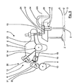
- FIG. 1 shows the essential elements of the invention.
- An internal combustion engine is provided with at least one combustion chamber 1, from which exhaust gas can be discharged by means of at least one exhaust valve 2, 2 ', wherein the internal combustion engine is provided with an engine brake device with a hydraulic additional valve control unit 3.
- the auxiliary valve control unit 3 is integrated into a connecting mechanism 5 connecting the exhaust valve 2, 2 'to a camshaft 4, the exhaust valve 2 being held in an intermediate open position Z when the engine braking device is actuated.
- the valves 2, 2 ' are moved by the reaction of the rocker arm 6 to the position of the camshaft 4 between a closed position S and an open position O back and forth. Only one of the exhaust valves 2, 2 'namely exhaust valve 2 can be kept temporarily or during a braking phase by the additional valve control unit 3 in the case of a braking operation in an intermediate open position Z.
- the internal combustion engine comprises a hydraulic valve clearance compensation mechanism 7 by which occurring in the course of wear of individual elements of the connecting mechanism 5 wear and thus a game within the system by adjusting individual elements is avoided.
- the connecting mechanism 5 further comprises a rocker arm 6 and an intermediate element 8 arranged between the rocker arm 6 and the outlet valve 2, 2 '.
- the intermediate element 8 is designed in the illustrated embodiment as a valve bridge 9 which couples two exhaust valves 2, 2' to one another tilting lever side adjustably mounted adjusting screw 10 is in contact.
- the adjusting screw 10 is connected via a coupling element 29 with the valve bridge 9, the coupling element 29 may be an integral part of the intermediate element 8 or an attached component of the intermediate element 8.
- the coupling element 29 is in the illustrated embodiment on the valve bridge 9 and can move away from this.
- the hydraulic additional valve control unit 3 provides a first piston-cylinder unit 11.
- the hydraulic valve clearance compensation mechanism 7 comprises a second piston-cylinder unit 12 which counteracts the occurrence of a valve clearance.
- the first piston-cylinder unit 11 is arranged in the illustrated embodiment in the valve bridge 9 and the second piston-cylinder unit 12 in the rocker arm 6.
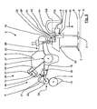
- connection mechanism 5 In the FIGS. 1 . 2 . 3 . 5 . 7 . 8th and 9 the connection mechanism 5 is always aligned on the base circle of the camshaft 4 and thus in its normal position G. In the FIGS. 4 and 6 the connection mechanism 5 is moved out of the basic position G by the cam 13 of the camshaft 4 into a position which brings the valves 2, 2 'into the open position O.
- the first and the second piston-cylinder unit 11, 12 is connected to the oil supply to a common oil source here in the storage area 14 of the rocker arm 6, wherein the first and second piston-cylinder unit 11, 12 respectively without interposition of the other piston Cylinder unit 11, 12 is connected to the oil source.
- oil is passed through an axial bore 15 to the center of the bearing 14 and from there via channel sections 16, 16 ', 16 "within the bearing 14 to the camshaft side of the rocker arm 6, to the valve bridge side of the rocker arm. 6 and to lubrication regions 17 for lubricating the rotational movement of the rocker arm 6 relative to the bearing 14.
- the channel section 16 merges into the oil passages 18, 18 'which guide the oil to bearings or the axes of rotation 19, 20 of a carrier body 21 and a roller 22, respectively
- the channel portion 18 ' also disposed in the rocker arm 6 directs the oil to the second piston-cylinder unit 12.
- the channel portion 16 guides the oil through a passage portion 23 to the adjusting screw 10 within which an axial oil guide bore (not shown) is located in turn, the oil leads to the valve bridge 9 and there in an arranged within the valve bridge 9 oil passage 24 to a pressure chamber 25 of the ers th piston-cylinder unit 11 leads.
- the rocker arm 6 is preferably provided with two legs 26, 26 'enclosing an angle ⁇ , the second piston-cylinder unit 12 being arranged in the leg 26 of the rocker arm 6 facing the camshaft 4, cf. FIG. 2 ,
- the second piston-cylinder unit 12 is arranged in the leg 26 'of the rocker arm 6, wherein the second piston-cylinder unit 12 is arranged in the region between a rocker arm bearing 14 and the valve bridge 9.
- the rocker arm 6 is constructed in several parts in the illustrated embodiment and comprises a base body 27 and a support body 21, wherein the support body 21 is rotatably mounted relative to the base body 27, wherein the relative mobility (arrow R) of the base body 27 and support body 21 through the second piston-cylinder unit 12 can be influenced.
- the element of the rocker arm 6 is defined, which is mechanically closer to the valve bridge 9 and the intermediate element 8.
- the carrier element 21 forms the carrier for the contact element 28 which is in contact with the camshaft 4.
- the contact element 28 may be a slider, compare FIG. 7 or include a roller 22.
- the axis of rotation 29 of the support body 21 may be aligned concentrically with the axis of rotation 14 of the main body 27 of the rocker arm 6 according to the drawing figures 7 and 8.
- the support body 21 is thus rotatably arranged on the main body 27 via the rotation axis 19 according to the drawing figures 1 to 6, wherein the rotational movement R of the support body 21 by action of the second piston-cylinder unit 12 on the one hand and on the other hand by the contact via the contact element 28 and / or the roller 22 is affected on the camshaft 4.
- the roller 22 drives on the cam 13
- the second piston-cylinder unit 12 behaves substantially - except for a slight deflection and rebound - rigid and initiates the movement of the cam 13 the rocker arm 6, so that it performs a rotational movement, which in turn acts on the valve bridge 9 via the adjusting screw 10 and this displaced in the direction of the combustion chamber 1 and thus the valves 2, 2 'in an open position O spends.
- the substantially rigid property of the second piston-cylinder unit 12 can be achieved by behaving essentially in the manner of a one-way valve.
- the longitudinal axis 31 of the second piston-cylinder unit 12 with a straight auxiliary line 32, the point of the retracted end position (cross-sectional center of the piston, in FIG. 1 marked "x") of the second piston-cylinder unit 12 is constructed with the rotational axis 20 of the pivot bearing, an angle ⁇ 45 ° to -45 °, including in particular an angle ⁇ of 10 ° to -10 °.
- the structure of the first and / or the second piston-cylinder unit 11, 12 respectively provides a preferably by a spring 41, 45 in the extended position biased piston 40, 44, a pressure chamber 25, 47 and a pressure chamber 25, 47 at least phasing blocking element 42, 46 before.
- a filled with oil pressure chamber 25, 47 and with simultaneous closure of the pressure chamber 25, 47 by the blocking element 42, 46 a blocking of the movement of the first and / or second piston / cylinder unit 11, 12 are executed.
- valve bridge 9 pressure chamber 25 of the first piston-cylinder unit 11 also provides a leading to the outside of the pressure chamber 25 oil passage 33, which is in phases closed by the anvil 34.
- This shutter stops at least as long as the valve bridge 9 remains in its basic position GS.
- the second piston-cylinder unit 12 comprises a disc 48 on which a cylindrical support means 49 having a through hole centrally in the bottom surface, is attached. Between the piston 44 and support means 49, a pressure chamber 47 is formed, which via the through hole with an anteroom connected is.
- the support means 49 is partially surrounded by an inner region of the piston 44.
- a step in the interlocking area serves as Endlagenbegrenzer the movement of the piston 44 relative to the support means 49.
- the through hole is closed in phases with a ball 51, wherein a spring 52 biases the ball 51 in its closed position, this spring is supported on a 52 Cage 53 off.
- the second piston-cylinder unit 12 and the bearing 19 of the support body 21 to the base body 27 is arranged and designed such that in short-term movements of the valves 2, 2 'influenced by the second piston-cylinder unit 12 movement R of the Carrier body 21 relative to the base body 27 to a negligible extent or not executed, preferably this is based to an insignificant extent or not performed movement substantially on the inertia of the rocker arm.
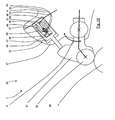
- valves 2, 2 ' are shown schematically with a distance 43, 43' from the valve bridge 9.
- a force acting on the valves 2, 2' initiates a sudden movement 35 of the valves 2, 2 '. Since the valves 2, 2 'are moved away from the valve bridge 9 due to this jump movement, the valve bridge 9 is in a quasi "floating state" because the support to the valves 2, 2' is missing.
- valve bridge could also - like the valves 2, 2 '- move towards the combustion chamber 1 and from the basic position GS away. This would cause the anvil 34 opens the oil passage 33 and can build up no oil pressure in the pressure chamber 25 and finally it would come to a blocking effect of the valve 2 in its intermediate open position.
- the inertia of the rocker arm 6, in particular that of the main body 27 can be used to the effect that the effect of the second piston-cylinder unit 12 on the acceleration of the rocker arm 6, in particular of the main body 27, so “delayed” is performed that it is not comes to a "pushing" of the valve bridge through the second piston-cylinder unit 12 or this happens only in an insubstantial for the overall course dimensions.
- the distance 43 or the path of the valve 2 from the valve bridge 9 should be ensured by the possible, held out path of the piston 40 within the cylinder of the first piston-cylinder unit 11.
- the spring 41 By the spring 41, a quick reaction of the first piston-cylinder unit 11 is achieved, which in turn allows a rapid filling of the enlarged by the piston movement pressure chamber 25.
- the first piston-cylinder unit 11 reacts with the result of the blocking effect by filling the pressure chamber 25 and the lock by the blocking element 42 faster than the second piston-cylinder unit 12 with the Vortemposweitergabe or force application to the valve bridge 9 and thus with the movement of the valve bridge 9 to the combustion chamber 1 out.
- the bearing area of the axis of rotation 19 of the support member 21 relative to the base body 27 and / or the storage of the rocker arm 6 at its Kipphebelellager 14 form such that an inertia is forced by the increased static friction the rocker arm 6 and its acceleration capability, so that the second piston-cylinder unit 12 can not or only insignificantly close a (short-term) distance 43, 43 'between the valve bridge 9 and the valves 2, 2' by moving the valve bridge 9.
- the valve bridge could briefly move in an inclined position.
- the camshaft 4 facing the first leg 26 of the rocker arm 6 and the exhaust valve 2, 2 'facing second leg 26' of the rocker arm 6 are each provided with at least one oil guide channel 18 ', 23 wherein the oil guide channels 18', 23 with the Oil source (here the bore 15) are connected and the oil, starting from the arranged in the region of the Kipphebellagers 14 oil source via the oil guide channels 18 ', 23 to the first and second piston-cylinder unit 11, 12 can be fed.
- a further oil guide channel 18 is additionally arranged in the first leg 26, which passes the oil to the storage area 19 of the carrier body 21 and channel sections in the carrier body 21 via this to the storage area 20 of the contact element 28.
- a vent channel 37 is provided, which emits a small amount of oil, for example, in the case of compression of the second piston-cylinder unit 12 to the environment of the rocker arm 6 , Additionally or alternatively, air can escape through the channel 37 of the rocker arm 6.
- the above-described arrangement of the first and second piston-cylinder unit 11, 12 according to the invention is particularly advantageous for overhead camshaft engines 4.
Landscapes
- Engineering & Computer Science (AREA)
- Mechanical Engineering (AREA)
- General Engineering & Computer Science (AREA)
- Valve Device For Special Equipments (AREA)
- Valve-Gear Or Valve Arrangements (AREA)
Priority Applications (1)
| Application Number | Priority Date | Filing Date | Title |
|---|---|---|---|
| PL11009800T PL2520773T3 (pl) | 2011-05-04 | 2011-12-13 | Silnik spalinowy z co najmniej jedną komorą spalania |
Applications Claiming Priority (2)
| Application Number | Priority Date | Filing Date | Title |
|---|---|---|---|
| DE102011100324 | 2011-05-04 | ||
| DE102011118537A DE102011118537A1 (de) | 2011-05-04 | 2011-11-15 | Brennkraftmaschine mit mindestens einem Brennraum |
Publications (3)
| Publication Number | Publication Date |
|---|---|
| EP2520773A2 true EP2520773A2 (fr) | 2012-11-07 |
| EP2520773A3 EP2520773A3 (fr) | 2013-03-27 |
| EP2520773B1 EP2520773B1 (fr) | 2014-07-02 |
Family
ID=45370386
Family Applications (1)
| Application Number | Title | Priority Date | Filing Date |
|---|---|---|---|
| EP11009800.1A Active EP2520773B1 (fr) | 2011-05-04 | 2011-12-13 | Moteur à combustion interne doté d'au moins un espace de combustion |
Country Status (7)
| Country | Link |
|---|---|
| US (1) | US8746208B2 (fr) |
| EP (1) | EP2520773B1 (fr) |
| CN (1) | CN102767408B (fr) |
| BR (1) | BR102012008925B1 (fr) |
| DE (1) | DE102011118537A1 (fr) |
| EA (1) | EA026598B1 (fr) |
| PL (1) | PL2520773T3 (fr) |
Cited By (4)
| Publication number | Priority date | Publication date | Assignee | Title |
|---|---|---|---|---|
| WO2015022071A1 (fr) * | 2013-08-12 | 2015-02-19 | Avl List Gmbh | Dispositif d'actionnement de soupape permettant de modifier la course de soupape |
| EP2851525A1 (fr) * | 2013-09-19 | 2015-03-25 | MAN Truck & Bus AG | Dispositif et procédé d'actionnement d'au moins une soupape d'échappement d'un moteur à combustion interne commandé par soupape |
| EP2959122A4 (fr) * | 2013-02-25 | 2016-10-05 | Jacobs Vehicle Systems Inc | Pistons de maître-cylindre et cylindre récepteur intégrés pour actionner des soupapes d'un moteur |
| WO2019117825A1 (fr) * | 2017-12-14 | 2019-06-20 | Ford Otomotiv Sanayi A. S. | Mécanisme de culbuteur |
Families Citing this family (9)
| Publication number | Priority date | Publication date | Assignee | Title |
|---|---|---|---|---|
| CN106150589B (zh) * | 2015-04-28 | 2019-01-15 | 上海尤顺汽车部件有限公司 | 一种单气门压缩释放型阀桥制动装置及方法 |
| DE102015016526A1 (de) * | 2015-12-19 | 2017-06-22 | Daimler Ag | Verfahren zum Betreiben einer Hubkolben-Verbrennungskraftmaschine |
| DE102018123125A1 (de) * | 2018-09-20 | 2020-03-26 | Schaeffler Technologies AG & Co. KG | Vorrichtung zur Durchführung einer Mehrzyklenmotorbremsung |
| KR20210041335A (ko) * | 2019-10-07 | 2021-04-15 | 현대자동차주식회사 | 압축 완화형 엔진 브레이크 장치 |
| CN112065525B (zh) * | 2020-09-09 | 2021-11-19 | 潍柴动力股份有限公司 | 一种摇臂机构及发动机总成 |
| CN112065524B (zh) * | 2020-09-11 | 2021-09-28 | 潍柴动力股份有限公司 | 一种摇臂总成及发动机 |
| US11377980B2 (en) * | 2020-12-02 | 2022-07-05 | Jiangsu Jointek Precision Machinery Co., Ltd | Self-resetting single-valve double-piston hydraulic drive device and method for overhead cam engine |
| EP4256181A4 (fr) | 2020-12-03 | 2024-11-20 | Jacobs Vehicle Systems, Inc. | Système d'actionneur rotatif de commande de l'actionnement des soupapes dans un moteur à combustion interne |
| CN120051627A (zh) | 2022-10-12 | 2025-05-27 | 康明斯有限公司 | 包括分立空动装置的气门致动系统 |
Family Cites Families (17)
| Publication number | Priority date | Publication date | Assignee | Title |
|---|---|---|---|---|
| US2036936A (en) * | 1932-04-04 | 1936-04-07 | Halford Frank Bernard | Valve gear for internal combustion engines |
| JPS5926768B2 (ja) * | 1976-07-27 | 1984-06-30 | トヨタ自動車株式会社 | 内燃機関のバルブ駆動装置 |
| JPS6098113A (ja) * | 1983-11-01 | 1985-06-01 | Nissan Motor Co Ltd | 弁作動切換装置付内燃機関のバルブクリアランス調整装置 |
| US5107803A (en) * | 1991-02-15 | 1992-04-28 | Alan Furnivall | Split-action rocker arm |
| SE504145C2 (sv) * | 1995-03-20 | 1996-11-18 | Volvo Ab | Avgasventilmekanism i en förbränningsmotor |
| SE521245C2 (sv) * | 1998-12-18 | 2003-10-14 | Volvo Lastvagnar Ab | Motorbromsappliceringssystem, metod för att minska motorhastigheten samt användning av systemet |
| US6394050B1 (en) * | 1999-09-15 | 2002-05-28 | Diesel Engine Retarders, Inc. | Actuator piston assembly for a rocker arm system |
| US6386160B1 (en) * | 1999-12-22 | 2002-05-14 | Jenara Enterprises, Ltd. | Valve control apparatus with reset |
| DE10349641A1 (de) * | 2003-10-24 | 2005-05-19 | Man Nutzfahrzeuge Ag | Motorstaubremsvorrichtung einer 4-Takt-Hubkolbenbrennkraftmaschine |
| WO2007078309A2 (fr) * | 2005-12-28 | 2007-07-12 | Jacobs Vehicle Systems, Inc. | Procede et systeme pour frein a cycle de resistance de fuite partielle |
| US7913656B2 (en) * | 2007-10-31 | 2011-03-29 | Ford Global Technologies, Llc | Variable displacement engine having selectively engageable rocker arm with positioning device |
| DE102008061412A1 (de) | 2008-07-11 | 2010-01-14 | Man Nutzfahrzeuge Ag | Hydraulischer Ventil- und EVB-Spielausgleich |
| CN101392667B (zh) * | 2008-10-30 | 2013-02-27 | 杨柳 | 使用单阀和阀桥的发动机制动装置和方法 |
| CN102459830A (zh) | 2009-06-02 | 2012-05-16 | 雅各布斯车辆系统公司 | 单排气气门桥制动方法和系统 |
| DE102009048143A1 (de) * | 2009-10-02 | 2011-04-07 | Man Nutzfahrzeuge Aktiengesellschaft | Brennkraftmaschine mit einer Motorbremseinrichtung |
| DE102009048104A1 (de) * | 2009-10-02 | 2011-04-07 | Man Nutzfahrzeuge Aktiengesellschaft | Brennkraftmaschine mit einer Motorbremseinrichtung |
| JP5436134B2 (ja) * | 2009-10-05 | 2014-03-05 | 株式会社オティックス | ロッカアーム及び動弁機構 |
-
2011
- 2011-11-15 DE DE102011118537A patent/DE102011118537A1/de not_active Withdrawn
- 2011-12-13 EP EP11009800.1A patent/EP2520773B1/fr active Active
- 2011-12-13 PL PL11009800T patent/PL2520773T3/pl unknown
-
2012
- 2012-04-13 EA EA201200487A patent/EA026598B1/ru not_active IP Right Cessation
- 2012-04-16 BR BR102012008925-4A patent/BR102012008925B1/pt active IP Right Grant
- 2012-05-02 US US13/462,142 patent/US8746208B2/en active Active
- 2012-05-04 CN CN201210148823.XA patent/CN102767408B/zh active Active
Non-Patent Citations (1)
| Title |
|---|
| None |
Cited By (7)
| Publication number | Priority date | Publication date | Assignee | Title |
|---|---|---|---|---|
| EP2959122A4 (fr) * | 2013-02-25 | 2016-10-05 | Jacobs Vehicle Systems Inc | Pistons de maître-cylindre et cylindre récepteur intégrés pour actionner des soupapes d'un moteur |
| WO2015022071A1 (fr) * | 2013-08-12 | 2015-02-19 | Avl List Gmbh | Dispositif d'actionnement de soupape permettant de modifier la course de soupape |
| US10830159B2 (en) | 2013-08-12 | 2020-11-10 | Avl List Gmbh | Valve-actuating device for varying the valve lift |
| EP2851525A1 (fr) * | 2013-09-19 | 2015-03-25 | MAN Truck & Bus AG | Dispositif et procédé d'actionnement d'au moins une soupape d'échappement d'un moteur à combustion interne commandé par soupape |
| RU2661921C2 (ru) * | 2013-09-19 | 2018-07-23 | Ман Трак Унд Бас Аг | Устройство и способ для приведения в действие по меньшей мере одного выпускного клапана, управляемого с помощью клапанов двигателя внутреннего сгорания |
| WO2019117825A1 (fr) * | 2017-12-14 | 2019-06-20 | Ford Otomotiv Sanayi A. S. | Mécanisme de culbuteur |
| US11255225B2 (en) | 2017-12-14 | 2022-02-22 | Ford Otomotsv Sanayi A. S. | Rocker arm mechanism |
Also Published As
| Publication number | Publication date |
|---|---|
| EA201200487A1 (ru) | 2013-05-30 |
| CN102767408A (zh) | 2012-11-07 |
| PL2520773T3 (pl) | 2014-12-31 |
| US8746208B2 (en) | 2014-06-10 |
| EA026598B1 (ru) | 2017-04-28 |
| BR102012008925A2 (pt) | 2013-06-18 |
| DE102011118537A1 (de) | 2012-11-08 |
| EP2520773B1 (fr) | 2014-07-02 |
| US20120279463A1 (en) | 2012-11-08 |
| BR102012008925B1 (pt) | 2021-02-02 |
| CN102767408B (zh) | 2017-03-01 |
| EP2520773A3 (fr) | 2013-03-27 |
Similar Documents
| Publication | Publication Date | Title |
|---|---|---|
| EP2520773B1 (fr) | Moteur à combustion interne doté d'au moins un espace de combustion | |
| EP3418513B1 (fr) | Dispositif de transmission de force | |
| DE10203621B4 (de) | Ventilsteuervorrichtung eines Verbrennungsmotors | |
| EP3638926B1 (fr) | Frein de stationnement destiné à une transmission automatique dans un véhicule automobile | |
| DE112014003482T5 (de) | Vorrichtung und Verfahren zur Einstellung des Spiels von Motorbremsen | |
| EP3434871B1 (fr) | Système de cames coulissantes | |
| DE202009016619U1 (de) | Ventiltrieb einer Brennkraftmaschine | |
| DE19650987A1 (de) | Bremssystem für einen Innenverbrennungsmotor | |
| WO2008012306A1 (fr) | Commande de soupape commutable d'un moteur à combustion interne | |
| WO2008110440A1 (fr) | Élément support commutable pour une commande de soupapes d'un moteur à combustion interne | |
| DE112023002761T5 (de) | Kipphebel zum Bremsen mit integrierter Hydraulikkapsel | |
| EP1974131B1 (fr) | Dispositif d'actionnement d'une soupape a gaz en va-et-vient | |
| EP3401517A1 (fr) | Levier moteur de soupape | |
| EP1364108B1 (fr) | Systeme de soupape d'echange gazeux pour moteur a combustion interne | |
| EP2722498A1 (fr) | Dispositif d'actionnement d'au moins une soupape d'échappement d'un moteur à combustion interne commandé par soupape | |
| EP1588027B1 (fr) | Culbuteur d'entrainement hydraulique | |
| EP3728821B1 (fr) | Dispositif de vanne pour un moteur à combustion interne | |
| DE102010027608A1 (de) | Steuertrieb einer Brennkraftmaschine | |
| EP1870610A2 (fr) | Système de levier et son procédé de montage | |
| DE19505725C2 (de) | Motorbremse | |
| EP3167168B1 (fr) | Mécanisme de distribution à commande mécanique | |
| EP3450708A1 (fr) | Système de cames coulissantes | |
| DE102018111185A1 (de) | Variabler Ventiltrieb eines Verbrennungskolbenmotors und Verfahren zu dessen Steuerung | |
| DE102004019280A1 (de) | Kupplung | |
| DE102022117873B3 (de) | Ventilanordnung für einen Ventiltrieb einer Brennkraftmaschine |
Legal Events
| Date | Code | Title | Description |
|---|---|---|---|
| PUAI | Public reference made under article 153(3) epc to a published international application that has entered the european phase |
Free format text: ORIGINAL CODE: 0009012 |
|
| AK | Designated contracting states |
Kind code of ref document: A2 Designated state(s): AL AT BE BG CH CY CZ DE DK EE ES FI FR GB GR HR HU IE IS IT LI LT LU LV MC MK MT NL NO PL PT RO RS SE SI SK SM TR |
|
| AX | Request for extension of the european patent |
Extension state: BA ME |
|
| PUAL | Search report despatched |
Free format text: ORIGINAL CODE: 0009013 |
|
| AK | Designated contracting states |
Kind code of ref document: A3 Designated state(s): AL AT BE BG CH CY CZ DE DK EE ES FI FR GB GR HR HU IE IS IT LI LT LU LV MC MK MT NL NO PL PT RO RS SE SI SK SM TR |
|
| AX | Request for extension of the european patent |
Extension state: BA ME |
|
| RIC1 | Information provided on ipc code assigned before grant |
Ipc: F01L 13/06 20060101AFI20130215BHEP Ipc: F01L 1/26 20060101ALI20130215BHEP Ipc: F01L 1/18 20060101ALI20130215BHEP Ipc: F01L 1/053 20060101ALI20130215BHEP |
|
| 17P | Request for examination filed |
Effective date: 20130604 |
|
| RIC1 | Information provided on ipc code assigned before grant |
Ipc: F01L 1/26 20060101ALI20140204BHEP Ipc: F01L 1/20 20060101ALI20140204BHEP Ipc: F01L 1/18 20060101ALI20140204BHEP Ipc: F01L 13/06 20060101AFI20140204BHEP Ipc: F01L 13/00 20060101ALI20140204BHEP Ipc: F01L 1/053 20060101ALI20140204BHEP |
|
| GRAP | Despatch of communication of intention to grant a patent |
Free format text: ORIGINAL CODE: EPIDOSNIGR1 |
|
| INTG | Intention to grant announced |
Effective date: 20140314 |
|
| GRAS | Grant fee paid |
Free format text: ORIGINAL CODE: EPIDOSNIGR3 |
|
| GRAA | (expected) grant |
Free format text: ORIGINAL CODE: 0009210 |
|
| AK | Designated contracting states |
Kind code of ref document: B1 Designated state(s): AL AT BE BG CH CY CZ DE DK EE ES FI FR GB GR HR HU IE IS IT LI LT LU LV MC MK MT NL NO PL PT RO RS SE SI SK SM TR |
|
| REG | Reference to a national code |
Ref country code: GB Ref legal event code: FG4D Free format text: NOT ENGLISH |
|
| REG | Reference to a national code |
Ref country code: CH Ref legal event code: EP Ref country code: AT Ref legal event code: REF Ref document number: 676060 Country of ref document: AT Kind code of ref document: T Effective date: 20140715 |
|
| REG | Reference to a national code |
Ref country code: IE Ref legal event code: FG4D Free format text: LANGUAGE OF EP DOCUMENT: GERMAN |
|
| REG | Reference to a national code |
Ref country code: DE Ref legal event code: R096 Ref document number: 502011003608 Country of ref document: DE Effective date: 20140814 |
|
| REG | Reference to a national code |
Ref country code: SE Ref legal event code: TRGR |
|
| REG | Reference to a national code |
Ref country code: NL Ref legal event code: T3 |
|
| REG | Reference to a national code |
Ref country code: LT Ref legal event code: MG4D |
|
| REG | Reference to a national code |
Ref country code: PL Ref legal event code: T3 |
|
| PG25 | Lapsed in a contracting state [announced via postgrant information from national office to epo] |
Ref country code: BG Free format text: LAPSE BECAUSE OF FAILURE TO SUBMIT A TRANSLATION OF THE DESCRIPTION OR TO PAY THE FEE WITHIN THE PRESCRIBED TIME-LIMIT Effective date: 20141002 Ref country code: GR Free format text: LAPSE BECAUSE OF FAILURE TO SUBMIT A TRANSLATION OF THE DESCRIPTION OR TO PAY THE FEE WITHIN THE PRESCRIBED TIME-LIMIT Effective date: 20141003 Ref country code: CZ Free format text: LAPSE BECAUSE OF FAILURE TO SUBMIT A TRANSLATION OF THE DESCRIPTION OR TO PAY THE FEE WITHIN THE PRESCRIBED TIME-LIMIT Effective date: 20140702 Ref country code: PT Free format text: LAPSE BECAUSE OF FAILURE TO SUBMIT A TRANSLATION OF THE DESCRIPTION OR TO PAY THE FEE WITHIN THE PRESCRIBED TIME-LIMIT Effective date: 20141103 Ref country code: ES Free format text: LAPSE BECAUSE OF FAILURE TO SUBMIT A TRANSLATION OF THE DESCRIPTION OR TO PAY THE FEE WITHIN THE PRESCRIBED TIME-LIMIT Effective date: 20140702 Ref country code: NO Free format text: LAPSE BECAUSE OF FAILURE TO SUBMIT A TRANSLATION OF THE DESCRIPTION OR TO PAY THE FEE WITHIN THE PRESCRIBED TIME-LIMIT Effective date: 20141002 Ref country code: LT Free format text: LAPSE BECAUSE OF FAILURE TO SUBMIT A TRANSLATION OF THE DESCRIPTION OR TO PAY THE FEE WITHIN THE PRESCRIBED TIME-LIMIT Effective date: 20140702 Ref country code: FI Free format text: LAPSE BECAUSE OF FAILURE TO SUBMIT A TRANSLATION OF THE DESCRIPTION OR TO PAY THE FEE WITHIN THE PRESCRIBED TIME-LIMIT Effective date: 20140702 |
|
| PG25 | Lapsed in a contracting state [announced via postgrant information from national office to epo] |
Ref country code: HR Free format text: LAPSE BECAUSE OF FAILURE TO SUBMIT A TRANSLATION OF THE DESCRIPTION OR TO PAY THE FEE WITHIN THE PRESCRIBED TIME-LIMIT Effective date: 20140702 Ref country code: CY Free format text: LAPSE BECAUSE OF FAILURE TO SUBMIT A TRANSLATION OF THE DESCRIPTION OR TO PAY THE FEE WITHIN THE PRESCRIBED TIME-LIMIT Effective date: 20140702 Ref country code: IS Free format text: LAPSE BECAUSE OF FAILURE TO SUBMIT A TRANSLATION OF THE DESCRIPTION OR TO PAY THE FEE WITHIN THE PRESCRIBED TIME-LIMIT Effective date: 20141102 Ref country code: RS Free format text: LAPSE BECAUSE OF FAILURE TO SUBMIT A TRANSLATION OF THE DESCRIPTION OR TO PAY THE FEE WITHIN THE PRESCRIBED TIME-LIMIT Effective date: 20140702 Ref country code: LV Free format text: LAPSE BECAUSE OF FAILURE TO SUBMIT A TRANSLATION OF THE DESCRIPTION OR TO PAY THE FEE WITHIN THE PRESCRIBED TIME-LIMIT Effective date: 20140702 |
|
| REG | Reference to a national code |
Ref country code: DE Ref legal event code: R097 Ref document number: 502011003608 Country of ref document: DE |
|
| PG25 | Lapsed in a contracting state [announced via postgrant information from national office to epo] |
Ref country code: DK Free format text: LAPSE BECAUSE OF FAILURE TO SUBMIT A TRANSLATION OF THE DESCRIPTION OR TO PAY THE FEE WITHIN THE PRESCRIBED TIME-LIMIT Effective date: 20140702 Ref country code: SK Free format text: LAPSE BECAUSE OF FAILURE TO SUBMIT A TRANSLATION OF THE DESCRIPTION OR TO PAY THE FEE WITHIN THE PRESCRIBED TIME-LIMIT Effective date: 20140702 Ref country code: EE Free format text: LAPSE BECAUSE OF FAILURE TO SUBMIT A TRANSLATION OF THE DESCRIPTION OR TO PAY THE FEE WITHIN THE PRESCRIBED TIME-LIMIT Effective date: 20140702 Ref country code: RO Free format text: LAPSE BECAUSE OF FAILURE TO SUBMIT A TRANSLATION OF THE DESCRIPTION OR TO PAY THE FEE WITHIN THE PRESCRIBED TIME-LIMIT Effective date: 20140702 |
|
| PLBE | No opposition filed within time limit |
Free format text: ORIGINAL CODE: 0009261 |
|
| STAA | Information on the status of an ep patent application or granted ep patent |
Free format text: STATUS: NO OPPOSITION FILED WITHIN TIME LIMIT |
|
| 26N | No opposition filed |
Effective date: 20150407 |
|
| PG25 | Lapsed in a contracting state [announced via postgrant information from national office to epo] |
Ref country code: BE Free format text: LAPSE BECAUSE OF NON-PAYMENT OF DUE FEES Effective date: 20141231 |
|
| PG25 | Lapsed in a contracting state [announced via postgrant information from national office to epo] |
Ref country code: LU Free format text: LAPSE BECAUSE OF FAILURE TO SUBMIT A TRANSLATION OF THE DESCRIPTION OR TO PAY THE FEE WITHIN THE PRESCRIBED TIME-LIMIT Effective date: 20141213 |
|
| REG | Reference to a national code |
Ref country code: CH Ref legal event code: PL |
|
| REG | Reference to a national code |
Ref country code: IE Ref legal event code: MM4A |
|
| PG25 | Lapsed in a contracting state [announced via postgrant information from national office to epo] |
Ref country code: CH Free format text: LAPSE BECAUSE OF NON-PAYMENT OF DUE FEES Effective date: 20141231 Ref country code: LI Free format text: LAPSE BECAUSE OF NON-PAYMENT OF DUE FEES Effective date: 20141231 Ref country code: IE Free format text: LAPSE BECAUSE OF NON-PAYMENT OF DUE FEES Effective date: 20141213 |
|
| PG25 | Lapsed in a contracting state [announced via postgrant information from national office to epo] |
Ref country code: SI Free format text: LAPSE BECAUSE OF FAILURE TO SUBMIT A TRANSLATION OF THE DESCRIPTION OR TO PAY THE FEE WITHIN THE PRESCRIBED TIME-LIMIT Effective date: 20140702 |
|
| REG | Reference to a national code |
Ref country code: FR Ref legal event code: PLFP Year of fee payment: 5 |
|
| PG25 | Lapsed in a contracting state [announced via postgrant information from national office to epo] |
Ref country code: SM Free format text: LAPSE BECAUSE OF FAILURE TO SUBMIT A TRANSLATION OF THE DESCRIPTION OR TO PAY THE FEE WITHIN THE PRESCRIBED TIME-LIMIT Effective date: 20140702 |
|
| PG25 | Lapsed in a contracting state [announced via postgrant information from national office to epo] |
Ref country code: MC Free format text: LAPSE BECAUSE OF FAILURE TO SUBMIT A TRANSLATION OF THE DESCRIPTION OR TO PAY THE FEE WITHIN THE PRESCRIBED TIME-LIMIT Effective date: 20140702 |
|
| PG25 | Lapsed in a contracting state [announced via postgrant information from national office to epo] |
Ref country code: MT Free format text: LAPSE BECAUSE OF FAILURE TO SUBMIT A TRANSLATION OF THE DESCRIPTION OR TO PAY THE FEE WITHIN THE PRESCRIBED TIME-LIMIT Effective date: 20140702 Ref country code: HU Free format text: LAPSE BECAUSE OF FAILURE TO SUBMIT A TRANSLATION OF THE DESCRIPTION OR TO PAY THE FEE WITHIN THE PRESCRIBED TIME-LIMIT; INVALID AB INITIO Effective date: 20111213 |
|
| GBPC | Gb: european patent ceased through non-payment of renewal fee |
Effective date: 20151213 |
|
| PG25 | Lapsed in a contracting state [announced via postgrant information from national office to epo] |
Ref country code: GB Free format text: LAPSE BECAUSE OF NON-PAYMENT OF DUE FEES Effective date: 20151213 |
|
| REG | Reference to a national code |
Ref country code: FR Ref legal event code: PLFP Year of fee payment: 6 |
|
| REG | Reference to a national code |
Ref country code: FR Ref legal event code: PLFP Year of fee payment: 7 |
|
| REG | Reference to a national code |
Ref country code: AT Ref legal event code: MM01 Ref document number: 676060 Country of ref document: AT Kind code of ref document: T Effective date: 20161213 |
|
| PG25 | Lapsed in a contracting state [announced via postgrant information from national office to epo] |
Ref country code: AT Free format text: LAPSE BECAUSE OF NON-PAYMENT OF DUE FEES Effective date: 20161213 |
|
| PG25 | Lapsed in a contracting state [announced via postgrant information from national office to epo] |
Ref country code: MK Free format text: LAPSE BECAUSE OF FAILURE TO SUBMIT A TRANSLATION OF THE DESCRIPTION OR TO PAY THE FEE WITHIN THE PRESCRIBED TIME-LIMIT Effective date: 20140702 |
|
| PG25 | Lapsed in a contracting state [announced via postgrant information from national office to epo] |
Ref country code: AL Free format text: LAPSE BECAUSE OF FAILURE TO SUBMIT A TRANSLATION OF THE DESCRIPTION OR TO PAY THE FEE WITHIN THE PRESCRIBED TIME-LIMIT Effective date: 20140702 |
|
| REG | Reference to a national code |
Ref country code: DE Ref legal event code: R081 Ref document number: 502011003608 Country of ref document: DE Owner name: MAN TRUCK & BUS SE, DE Free format text: FORMER OWNER: MAN TRUCK & BUS AG, 80995 MUENCHEN, DE |
|
| PGFP | Annual fee paid to national office [announced via postgrant information from national office to epo] |
Ref country code: IT Payment date: 20251218 Year of fee payment: 15 |
|
| PGFP | Annual fee paid to national office [announced via postgrant information from national office to epo] |
Ref country code: FR Payment date: 20251230 Year of fee payment: 15 Ref country code: NL Payment date: 20251222 Year of fee payment: 15 |
|
| PGFP | Annual fee paid to national office [announced via postgrant information from national office to epo] |
Ref country code: TR Payment date: 20251202 Year of fee payment: 15 |
|
| PGFP | Annual fee paid to national office [announced via postgrant information from national office to epo] |
Ref country code: SE Payment date: 20251222 Year of fee payment: 15 |
|
| PGFP | Annual fee paid to national office [announced via postgrant information from national office to epo] |
Ref country code: PL Payment date: 20251209 Year of fee payment: 15 |
|
| PGFP | Annual fee paid to national office [announced via postgrant information from national office to epo] |
Ref country code: DE Payment date: 20251229 Year of fee payment: 15 |