EP2520780A1 - Gasmotor mit hilfskammer - Google Patents
Gasmotor mit hilfskammer Download PDFInfo
- Publication number
- EP2520780A1 EP2520780A1 EP10840776A EP10840776A EP2520780A1 EP 2520780 A1 EP2520780 A1 EP 2520780A1 EP 10840776 A EP10840776 A EP 10840776A EP 10840776 A EP10840776 A EP 10840776A EP 2520780 A1 EP2520780 A1 EP 2520780A1
- Authority
- EP
- European Patent Office
- Prior art keywords
- chamber
- nozzle
- auxiliary
- nozzles
- auxiliary chamber
- Prior art date
- Legal status (The legal status is an assumption and is not a legal conclusion. Google has not performed a legal analysis and makes no representation as to the accuracy of the status listed.)
- Withdrawn
Links
Images



Classifications
-
- F—MECHANICAL ENGINEERING; LIGHTING; HEATING; WEAPONS; BLASTING
- F02—COMBUSTION ENGINES; HOT-GAS OR COMBUSTION-PRODUCT ENGINE PLANTS
- F02B—INTERNAL-COMBUSTION PISTON ENGINES; COMBUSTION ENGINES IN GENERAL
- F02B19/00—Engines characterised by precombustion chambers
- F02B19/10—Engines characterised by precombustion chambers with fuel introduced partly into pre-combustion chamber, and partly into cylinder
- F02B19/1019—Engines characterised by precombustion chambers with fuel introduced partly into pre-combustion chamber, and partly into cylinder with only one pre-combustion chamber
- F02B19/1023—Engines characterised by precombustion chambers with fuel introduced partly into pre-combustion chamber, and partly into cylinder with only one pre-combustion chamber pre-combustion chamber and cylinder being fed with fuel-air mixture(s)
-
- F—MECHANICAL ENGINEERING; LIGHTING; HEATING; WEAPONS; BLASTING
- F02—COMBUSTION ENGINES; HOT-GAS OR COMBUSTION-PRODUCT ENGINE PLANTS
- F02B—INTERNAL-COMBUSTION PISTON ENGINES; COMBUSTION ENGINES IN GENERAL
- F02B19/00—Engines characterised by precombustion chambers
- F02B19/10—Engines characterised by precombustion chambers with fuel introduced partly into pre-combustion chamber, and partly into cylinder
- F02B19/1019—Engines characterised by precombustion chambers with fuel introduced partly into pre-combustion chamber, and partly into cylinder with only one pre-combustion chamber
- F02B19/108—Engines characterised by precombustion chambers with fuel introduced partly into pre-combustion chamber, and partly into cylinder with only one pre-combustion chamber with fuel injection at least into pre-combustion chamber, i.e. injector mounted directly in the pre-combustion chamber
-
- F—MECHANICAL ENGINEERING; LIGHTING; HEATING; WEAPONS; BLASTING
- F02—COMBUSTION ENGINES; HOT-GAS OR COMBUSTION-PRODUCT ENGINE PLANTS
- F02B—INTERNAL-COMBUSTION PISTON ENGINES; COMBUSTION ENGINES IN GENERAL
- F02B19/00—Engines characterised by precombustion chambers
- F02B19/12—Engines characterised by precombustion chambers with positive ignition
-
- F—MECHANICAL ENGINEERING; LIGHTING; HEATING; WEAPONS; BLASTING
- F02—COMBUSTION ENGINES; HOT-GAS OR COMBUSTION-PRODUCT ENGINE PLANTS
- F02B—INTERNAL-COMBUSTION PISTON ENGINES; COMBUSTION ENGINES IN GENERAL
- F02B19/00—Engines characterised by precombustion chambers
- F02B19/16—Chamber shapes or constructions not specific to sub-groups F02B19/02 - F02B19/10
-
- F—MECHANICAL ENGINEERING; LIGHTING; HEATING; WEAPONS; BLASTING
- F02—COMBUSTION ENGINES; HOT-GAS OR COMBUSTION-PRODUCT ENGINE PLANTS
- F02B—INTERNAL-COMBUSTION PISTON ENGINES; COMBUSTION ENGINES IN GENERAL
- F02B19/00—Engines characterised by precombustion chambers
- F02B19/16—Chamber shapes or constructions not specific to sub-groups F02B19/02 - F02B19/10
- F02B19/18—Transfer passages between chamber and cylinder
-
- Y—GENERAL TAGGING OF NEW TECHNOLOGICAL DEVELOPMENTS; GENERAL TAGGING OF CROSS-SECTIONAL TECHNOLOGIES SPANNING OVER SEVERAL SECTIONS OF THE IPC; TECHNICAL SUBJECTS COVERED BY FORMER USPC CROSS-REFERENCE ART COLLECTIONS [XRACs] AND DIGESTS
- Y02—TECHNOLOGIES OR APPLICATIONS FOR MITIGATION OR ADAPTATION AGAINST CLIMATE CHANGE
- Y02T—CLIMATE CHANGE MITIGATION TECHNOLOGIES RELATED TO TRANSPORTATION
- Y02T10/00—Road transport of goods or passengers
- Y02T10/10—Internal combustion engine [ICE] based vehicles
- Y02T10/12—Improving ICE efficiencies
Definitions
- the present invention relates to a divided-chamber gas engine including an auxiliary combustion chamber (an auxiliary chamber), and particularly to nozzles (nozzle holes) through which a combustion gas is injected from the auxiliary combustion chamber of the gas engine into a main combustion chamber.
- Divided-chamber gas engines include a main combustion chamber (which may be hereinafter referred to as a "main chamber”) and an auxiliary combustion chamber (which may be hereinafter referred to as an "auxiliary chamber”) connected to the main combustion chamber via nozzles.
- a lean air-fuel mixture (a fuel gas) is supplied to the main chamber through an air supply valve.
- the lean air-fuel mixture is produced by mixing a gaseous fuel and supplied air.
- the lean air-fuel mixture is such that air that is greater in amount than a theoretical air requirement is mixed into the fuel. Accordingly, the excess air ratio ⁇ of the lean air-fuel mixture is high (e.g., ⁇ is approximately 2).
- the auxiliary chamber is provided with a spark plug.
- a rich air-fuel mixture (a fuel gas for ignition), the excess air ratio ⁇ of which is 1 or lower, is supplied to the auxiliary chamber.
- the spark plug provided in the auxiliary chamber is fired and thereby the fuel gas for ignition in the auxiliary chamber is ignited.
- a flame produced in the auxiliary chamber propagates such that the flame front spreads from the spark plug in a spherical manner.
- a high-temperature fuel gas jets into the main chamber in the form of jet flames through a plurality of nozzles. From the jet flames, the flame propagates to the lean fuel gas in the main chamber.
- the temperature of the inner wall surface of the auxiliary chamber reaches approximately 1000 °C.
- the plurality of nozzles connecting the auxiliary chamber and the main chamber are open radially at the bottom part of the auxiliary chamber. Accordingly, the jet flames that jet into the main chamber through the nozzles spread within the main chamber in a distributed manner. It is necessary for the jet flames, which are injected from the auxiliary chamber into the main chamber through the nozzles, to have sufficient intensity for igniting the fuel gas in the main chamber, that is, sufficient injection quantity and jet velocity. In consideration of the above-described combustion in the main chamber, the nozzles are designed such that the intensity of the jet flames becomes optimal.
- the inner wall of the auxiliary chamber of the divided-chamber gas engine is formed of a nickel-based alloy (e.g., Inconel).
- the nozzles (nozzle holes) connecting the auxiliary chamber and the main chamber of the divided-chamber gas engine are formed as straight pipes by machining. If such a conventional divided-chamber gas engine is operated for a long period of time, the edge of the nozzles' inlets at the auxiliary chamber side becomes deformed. As mentioned above, the temperature in the auxiliary chamber becomes 1000 °C or higher. Accordingly, the inner wall surface of the auxiliary chamber is repeatedly subjected to heating and cooling cycles, in which the inner wall surface expands due to exposure to a high-temperature atmosphere and contracts when cooling down.
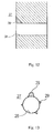
- Fig. 12 and Fig. 13 show an edge-chipped state of the opening edge (i.e., the edge of the inlet) of the nozzle at the auxiliary chamber side.
- Fig. 12 is a cross-sectional view of the nozzle along the axial direction, and Fig. 13 shows the nozzle seen from the auxiliary chamber side.
- Fig. 12 shows a state where chipping 29 has occurred at the opening edge of a nozzle 28 at an auxiliary chamber 27 side. Due to the chipping 29, the corner of the edge of the inlet of the nozzle 28 is partially cut out and rounded. If such chipping 29 occurs at multiple points at the opening edge of the nozzle 28 at the auxiliary chamber 27 side, then the opening edge of the inlet of the nozzle 28 becomes like a deformed star shape as shown in Fig. 13 .
- Chipping and cracks at the edge of the inlet of the nozzle cause a change in the intensity of a jet flame, which may lead to a decrease in the engine's combustion performance.
- divided-chamber gas engines are designed so that the engines can exert predetermined functions under optimized conditions, under the assumption that the edge of the inlet of each nozzle is in perfect conditions where there is no chipping or the like at the edge. If chipping or cracks occur at the edge of the inlet of the nozzle, the cross-sectional shape of the nozzle changes. As a result, the intensity of a jet flame that jets out though the nozzle also changes. For example, if the diameter of the nozzle increases, then the intensity of the jet flame decreases.
- the length of the jet flame becomes insufficient.
- the degree of such chipping and cracks is not necessarily the same among a plurality of nozzles. Accordingly, the jet flame intensity becomes different from nozzle to nozzle. If an ignition environment in the main chamber becomes less uniform than that originally designed, it may result in a decrease in the engine's combustion efficiency.
- Patent Literature 1 discloses an invention in relation to nozzle holes of a swirl chamber type combustion chamber of a diesel engine that is manually operable in a low-temperature atmosphere.
- Patent Literature 1 discloses that an inlet, at a swirl chamber side, of a main nozzle hole with two side nozzle holes positioned at its sides is chamfered.
- the nozzle hole used in the diesel engine disclosed in Patent Literature 1 is a single nozzle hole having a large aperture diameter. Since a fluid that passes through the nozzle hole is used as a fuel, its temperature is low and there is no possibility that crack-like flaws occur at the inlet or in the wall of the nozzle hole.
- this nozzle hole is different from the technical nature of the nozzle holes of a divided-chamber gas engine for injecting jet flames from the auxiliary chamber into the main chamber.
- the chamfering disclosed in Patent Literature 1 is intended to merely form an obtuse-angled edge for the purpose of preventing a fuel that is jetted into the swirl chamber from splashing by hitting the rim of the nozzle hole.
- Patent Literature 2 discloses a fuel combustion system for an engine, which is configured to supply jet flames from an auxiliary combustion chamber to a main combustion chamber through ejection passages at a speed greater than the speed of sound.
- Patent Literature 2 discloses that the ejection passages for ejecting a combustion gas from the auxiliary combustion chamber to the main combustion chamber include an inlet portion having a conical internal surface.
- the conical internal surface is inclined with respect to a central axis by an angle in the range of 15° to 30°.
- the conical internal surface is an inclined surface formed at the inlet side of tube-shaped ejection passages, which are formed in a venturi tube-like shape for the purpose of ejecting a fluid at high speed. Therefore, the conical internal surface does not have a function of suppressing cracks and edge chipping at the inlet portion of the passages.
- a problem to be solved by the present invention is to provide a divided-chamber gas engine including a main combustion chamber (a main chamber) and an auxiliary combustion chamber (an auxiliary chamber), the divided-chamber gas engine being capable of maintaining stable combustion in the main combustion chamber while suppressing degradation in combustion performance.
- a divided-chamber gas engine is a gas engine configured to inject a combustion gas from an auxiliary combustion chamber through a plurality of nozzles, through which the auxiliary combustion chamber and a main combustion chamber are in communication with each other, so as to ignite a fuel in the main combustion chamber.
- An opening edge, at the auxiliary combustion chamber side, of each of the plurality of nozzles has a chamfered shape.
- the chamfered shape is a round chamfered shape, and the opening edge is formed to have a curved surface.
- a portion, having the chamfered shape, of the opening edge, at the auxiliary combustion chamber side, of each of the plurality of nozzles is spaced apart from a portion, having the chamfered shape, of the opening edge, at the auxiliary combustion chamber side, of the other of the plurality of nozzles, such that interference between the portions having the chamfered shape is prevented.
- the curved surface has a curvature radius greater than or equal to a diameter of each nozzle.
- the curved surface has a curvature radius which may be set, such that a temperature increase or decrease at the opening edge, at the auxiliary combustion chamber side, of each of the plurality of nozzles is less than a temperature increase or decrease at a portion of an inner wall of the auxiliary combustion chamber, the portion being a closest portion of the inner wall to the main combustion chamber.
- the edge of the inlet of each nozzle at the auxiliary combustion chamber side is formed into a curved surface. Therefore, at the inlet of the nozzle, there is no edge that tends to be chipped. This makes it possible to suppress a phenomenon where cracked portions partially come off, to prevent deformation of the nozzle's cross section, and to suppress degradation in the combustion performance in the main combustion chamber.
- Fig. 1 is a conceptual diagram showing a structure of the divided-chamber gas engine according to the embodiment of the present invention.
- the divided-chamber gas engine according to the present embodiment includes a two-stage combustion chamber including a main combustion chamber (which may be hereinafter referred to as a "main chamber”) 1 and an auxiliary combustion chamber (which may be hereinafter referred to as an "auxiliary chamber") 2 connected to the main chamber 1 via a plurality of nozzles 9.
- the divided-chamber gas engine is a gas engine configured to perform so-called two-stage combustion, in which a lean air-fuel mixture, i.e., a fuel, supplied into the main chamber 1 is ignited by high-temperature jet flames that jet out from the auxiliary chamber 2 through the nozzles 9.
- a lean air-fuel mixture i.e., a fuel
- the main chamber 1 is formed within a cylinder 18.
- a piston 7 configured to move in a sliding manner within the cylinder 18.
- the piston 7 is connected to a drive shaft 19 via a crank 8.
- the drive shaft 19 rotates via the crank 8.
- an air supply pipe 14 connected to an air supply source 22.
- An air supply valve 15 configured to open and close between the air supply pipe 14 and the main chamber 1 is provided between the air supply pipe 14 and the main chamber 1.
- the air supply pipe 14 is connected to a fuel gas source 21 via a fuel supply pipe 24.
- the fuel gas is LNG, for example.
- the fuel supply pipe 24 is provided with a main solenoid valve 4 which is configured to adjust the amount of fuel gas supplied to the air supply pipe 14.
- a controller that is not shown generates a command in synchronization with an operation of the air supply valve 15 of the main chamber 1.
- the main solenoid valve 4 opens for a predetermined period.
- a predetermined amount of fuel gas is supplied from the fuel gas source 21 to the air supply pipe 14 through the fuel supply pipe 24.
- a lean air-fuel mixture (a fuel gas) is produced.
- the air-fuel mixture is thicker than a theoretical air-fuel ratio, then the air-fuel mixture is called a rich air-fuel mixture, and also, if the air-fuel mixture is thinner than the theoretical air-fuel ratio, then the air-fuel mixture is called a lean air-fuel mixture.
- the produced lean air-fuel mixture is supplied from the air supply pipe 14 to the main chamber 1 when the air supply valve 15 is opened.
- Combustion of the lean air-fuel mixture is lean burn (lean combustion), in which the amount of NOx to be produced is small.
- An exhaust gas pipe 16 which leads to an exhaust gas part 23 (i.e., to the outside), is connected to the upper part of the main chamber 1.
- An exhaust gas valve 17 configured to open and close between the exhaust gas pipe 16 and the main chamber 1 is provided between the exhaust gas pipe 16 and the main chamber 1. When the exhaust gas valve 17 is opened, a flue gas is discharged from the main chamber 1 to the exhaust gas part 23 through the exhaust gas pipe 16.
- the auxiliary chamber 2 is provided with a spark plug 3. Further, the auxiliary chamber 2 is connected to the fuel gas source 21 via a fuel supply pipe 25.
- the fuel supply pipe 25 is provided with an auxiliary solenoid valve 5 for adjusting the amount of fuel gas supplied to the auxiliary chamber 2, and a check valve 6 for preventing a reverse flow of the fuel gas from the auxiliary chamber 2 to the fuel supply pipe 25.
- the auxiliary solenoid valve 5 opens for a predetermined period in response to a command generated by the controller which is not shown. As a result, the fuel gas that is in a necessary amount is supplied from the fuel gas source 21 to the auxiliary chamber 2 through the fuel supply pipe 25 and the check valve 6.
- Fig. 2 is a cross-sectional view showing the bottom part of the auxiliary chamber 2.
- the bottom part is provided with nozzles (nozzle holes).
- Fig. 2 contains an enlarged cross-sectional view that shows a portion around a nozzle 9 in an enlarged manner.
- the bottom part of the auxiliary chamber 2 is formed to protrude into the main chamber 1.
- the bottom part of the auxiliary chamber 2 has a semi-spherical shape having a central axis extending in a direction in which the piston 7 moves.
- the nozzles 9 are formed in the bottom part of the auxiliary chamber 2, and allow the main chamber 1 and the auxiliary chamber 2 to be in communication with each other.
- openings (serving as inlets at the auxiliary chamber 2 side) of the respective nozzles 9 are arranged on a single circle, the center of which coincides with the central axis.
- the openings of the respective nozzles 9 are arranged on the single circle, the center of which coincides with the central axis of the auxiliary chamber 2.
- the nozzles 9 are formed to radially extend through the bottom wall of the auxiliary chamber 2, such that the radial extending directions of the respective nozzles 9 center on a particular point on the central axis of the auxiliary chamber 2.
- Each nozzle 9 has substantially the same nozzle diameter and nozzle length. Accordingly, jet flames that jet into the main chamber 1 through the respective nozzles 9 have substantially the same intensity. Therefore, the jet flames evenly jet into the main chamber 1.
- the fuel gas is supplied to the auxiliary chamber 2 at the same time as the lean air-fuel mixture is sucked into the main chamber 1 in a suction stroke. Since the nozzles 9 are always in the state of communication, the lean air-fuel mixture flows into the auxiliary chamber 2 when the piston 7 is lifted in the following compression stroke.
- the fuel gas is supplied from the fuel gas source 21 to the auxiliary chamber 2 through the fuel supply pipe 25 in an amount that corresponds to the volume of the auxiliary chamber, and the supplied fuel gas is compressed to 1/10.
- the lean air-fuel mixture with the excess air ratio ⁇ of approximately 2 is supplied from the inside of the main chamber 1 to the auxiliary chamber 2 through the nozzles 9 in an amount that corresponds to 9/10 of the volume of the auxiliary chamber.
- the fuel gas and the lean air-fuel mixture are mixed in the auxiliary chamber 2, and becomes an air-fuel mixture with the excess air ratio ⁇ of approximately 1, that is, an air-fuel mixture with the theoretical air-fuel ratio
- the air-fuel mixture is ignited in the auxiliary chamber 2.
- the air-fuel mixture while being combusted, jets into the main chamber 1 through the nozzles 9 in the form of high-temperature jet flames.
- the lean air-fuel mixture in the main chamber 1 is ignited by the jet flames and explodes, and the resultant force lowers the piston 7.
- the drive shaft 19 rotates via the crank 8, accordingly.
- a combustion gas that is produced in the main chamber 1 is released to the exhaust gas part 23 (i.e., to the outside) through the exhaust gas pipe 16 when the exhaust gas valve 17 is opened.
- Each nozzle 9 has such a shape that the edge of the nozzle's inlet at the auxiliary chamber 2 side, i.e., the corner of the opening edge at the auxiliary chamber 2 side, is chamfered.
- the chamfered shape include a shape in which the corner is rounded and a shape in which the corner is cut out diagonally (the diagonal angle is not particularly limited).
- One of these shapes is selected depending on machining conditions.
- the chamfered shape is desirably a round chamfered shape since such a shape does not allow a sharp ridge to be formed at a position where the inner wall of the auxiliary chamber 2 and the inner wall of the nozzle join.
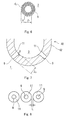
- FIG. 3 is an enlarged cross-sectional view showing a nozzle shape according to the present embodiment.
- the edge of the inlet of the nozzle 9 at the auxiliary chamber 2 side is chamfered such that the corner of the opening edge is rounded, and as a result, a curved surface 11 with a curvature radius R is formed.
- a right-angled edge, nor a nearly right-angled edge such as an acute-angled or obtuse-angled edge, both of which tend to be chipped, is formed at the opening edge of the nozzle 9 at the auxiliary chamber 2 side.
- a right-angled corner or a nearly right-angled corner such as an acute-angled or obtuse-angled corner, is formed at the opening edge of the nozzle 9 at the auxiliary chamber 2 side, then the temperature of such a cornered portion increases more easily than other portions. For example, assume a case where there is a corner formed at the opening edge of the nozzle 9 at the auxiliary chamber 2 side and the temperature variation range of the corner is approximately 50 to 1000 °C. In this case, the temperature variation range of other portions, different from the corner, of the bottom wall in the auxiliary chamber 2 remains approximately 50 to 700 °C.
- the temperature of the corner easily increases to a significantly higher temperature than the temperature of other portions.
- the temperature variation range of the opening edge and its surrounding portions is narrower, which realizes more uniform temperature distribution.
- the highest temperature in the temperature variation range is lower. Therefore, heat stress exerted on the opening edge of the nozzle 9 at the auxiliary chamber 2 side is reduced, and the degree of thermal fatigue is reduced as compared to a case where a corner is formed.
- an auxiliary chamber forming body 40 within which the auxiliary chamber 2 is formed, includes a base portion 41 and a protruding portion 42 which is formed in a manner to protrude from the base portion 41 toward the main chamber 1.
- the protruding portion 42 has a cylindrical shape, one end of which is open whereas the other end of which is closed and round shaped.
- the longitudinal section of the protruding portion 42 along the central axis is substantially U-shaped.
- the tip of the protruding portion 42 is inserted in the main chamber 1, and the plurality of nozzles 9 are formed in the inserted portion.
- the base portion 41 is cooled down by cooling means 44 which is, for example, cooling water.
- cooling means 44 which is, for example, cooling water.
- a position where the temperature increases most easily is a tip 43 of the protruding portion 42 which is the most distant portion from the cooling means 44.
- the tip 43 is the closest point of the protruding portion 42 to the main chamber 1.
- the curvature radius R is set such that a temperature increase or decrease at the opening edge of each nozzle 9 in the inner wall of the auxiliary chamber 2 becomes less than or equal to a temperature increase or decrease at the tip 43 of the protruding portion 42, which is the closest point of the protruding portion 42 to the main chamber 1.
- the thermal conduction area of the tip 43 of the protruding portion 42 is a tip portion thermal conduction area A 1 (indicated by diagonal hatching in Fig. 5 ).
- a distance by which heat is conducted from the tip 43 of the protruding portion 42 to the cooling means 44 is a tip portion thermal conductive distance L 1 .
- the area of the curved surface 11 i.e., the area of a portion having a chamfered shape of the opening edge of one nozzle 9 at the auxiliary chamber 2 side is an opening thermal conduction area A 2 (indicated by diagonal hatching in Fig. 6 ).
- a distance by which heat is conducted from the curved surface 11 of the opening edge of the nozzle 9 to the cooling means 44 is an opening thermal conduction distance L 2 .
- the amount of heat that a portion of the inner wall of the auxiliary chamber 2 receives owing to combustion can be represented by the product of the thermal conductivity of the portion per unit area and the area of the portion. Under this theory, a relationship represented by Equation 1 below is obtained.
- Equation 1 indicates that the total of the opening thermal conduction areas A 2 of n nozzles 9 formed in the auxiliary chamber forming body 40 is greater than the tip portion thermal conduction area A 1 multiplied by the proportion of the opening thermal conduction distance L 2 to the tip portion thermal conductive distance L 1 .
- the curvature radius R of the curved surface 11 may be any value that allows Equation 1 to be satisfied. That is, the minimum value of the curvature radius R of the curved surface 11 may be set based on Equation 1.
- the opening thermal conduction area A 2 is great since the greater the opening thermal conduction area A 2 , the more the amount of heat to be dissipated from the opening edge of the nozzle 9 to the cooling means 44 and the more suppressed the increase in the temperature at the opening edge of the nozzle 9.
- the diameter (internal diameter) D of each nozzle 9 according to the present embodiment is several mm to ten-odd mm.
- the curved surface 11 formed at the opening edge of the nozzle 9 flares out toward the outside such that the diameter increases. Almost damaged portions of the wall surface in the auxiliary chamber 2 are those positioned several mm away from the inner wall of the nozzle 9. Therefore, the curvature radius R, which satisfies the relationship of the above Equation 1, of the curved surface 11 of the opening edge of the nozzle 9 at the auxiliary chamber 2 side may be, for example, greater than or equal to the nozzle diameter D.
- the curvature radius R of the curved surface 11 is greater than or equal to the nozzle diameter D, then the curvature radius R of the inlet of the nozzle 9 is sufficiently great and the inlet has no acute-angled portion. Therefore, an occurrence of a phenomenon where cracked portions are torn away and chipped is suppressed. Accordingly, chipping of the edge is reduced. Further, an incident angle at which an energy line from the inside of the auxiliary chamber 2 hits the curved surface 11 of the opening edge of the nozzle 9 is greater than in a case where the auxiliary chamber 2 side of the opening edge of the nozzle 9 is a flat surface. Therefore, damage to the curved surface 11 is reduced.
- the maximum value of the curvature radius R of the curved surface 11 is not particularly limited. However, the length of the nozzle 9 decreases in accordance with an increase in the curvature radius R of the curved surface 11. Therefore, it is desired that the curvature radius R is in a range that allows the nozzle 9 to have such a length as to be able to jet out a jet flame.
- Fig. 7 is a cross-sectional view of the bottom part of the auxiliary chamber, for use in describing a relationship between the thickness of the bottom wall of the auxiliary chamber and the curvature radius of the curved surface. As shown in Fig. 7 , when the thickness of the bottom wall of the auxiliary chamber forming body 40 is L 3 , the curvature radius R is desirably 0.5 times, or less, of the thickness L 3 of the bottom wall.
- Fig. 8 is a conceptual diagram illustrating the arrangement of the nozzles according to the present embodiment.
- Fig. 4 shows only three nozzles among the plurality of nozzles 9 formed in the auxiliary chamber 2.
- the curvature radius R of the curved surface 11 is great since the greater the curvature radius R, the less the damage to the nozzle 9.
- the curved surface 11 formed at the opening edge of one nozzle 9 overlaps (interferes) with the curved surface 11 formed at the opening edge of the adjacent nozzle 9, then there is a possibility that even slight deformation occurring at the curved surfaces 11 causes a change in the boundary of a fluid flowing into the nozzles 9.
- the shapes of jet flames that are formed when passing through respective adjacent nozzles 9 become different from each other. This may cause a combustion state different from the one originally designed, resulting in degradation of the combustion performance in the main chamber 1. Therefore, it is preferred that a distance between nozzles 9 and the size of the curved surface 11 of each nozzle 9 are adjusted, such that a distance L is obtained between the ends of respective curved surfaces 11 formed at the opening edges of adjacent nozzles 9.
- each nozzle 9 at the main chamber 1 side may also be chambered.
- the edge of the inlet of each nozzle 9 at the main chamber 1 side may have such a chamfered shape that the corner of the edge is either rounded or cut out diagonally. If the opening edge of each nozzle 9 at the main chamber 1 side has such a chamfered shape, the passage resistance is reduced when the lean air-fuel mixture flows from the main chamber 1 to the auxiliary chamber 2. This makes it possible to reduce fluid pressure loss.
- the edge may act as a flint and cause an ignition, thereby causing knocking.
- the edge is made obtuse, and thereby knocking can be suppressed.
- Fig. 9 is an enlarged photo showing the openings of nozzles 9 at the auxiliary chamber 2 side after a divided-chamber gas engine including an auxiliary chamber forming body according to a working example of the present invention has been operated for 4000 hours under particular operation conditions.
- the opening edge, at the auxiliary chamber 2 side, of each nozzle 9 formed in the auxiliary chamber forming body according to the working example has a round chamfered shape.
- FIG. 10 is an enlarged photo showing the openings of nozzles 9 at the auxiliary chamber 2 side after a divided-chamber gas engine including an auxiliary chamber forming body according to a comparative example has been operated for 1000 hours under the same operation conditions as above.
- the opening edge, at the auxiliary chamber 2 side, of each nozzle 9 formed in the auxiliary chamber forming body according to the comparative example had a substantially right-angled corner before the operation.
- Fig. 10 that, after the operation, the opening edge at the auxiliary chamber 2 side was deformed due to a large number of deep cracks and chipping.
- temporal changes in the shape of the opening edge of the nozzle 9 are significantly suppressed when the opening edge of the nozzle 9 at the auxiliary chamber 2 side has a chamfered shape.
- the intensity of the jet flame that jets into the main chamber 1 through the nozzle 9 changes.
- the jet flame becomes short if the nozzle diameter increases due to such a change in the cross-sectional shape of the nozzle 9.
- spontaneous ignition of the air-fuel mixture in the cylinder 18 i.e., knocking
- General gas engines have a function of preventing knocking. Therefore, under conditions where knocking tends to occur, control for preventing the knocking is performed. Consequently, the combustion efficiency of the gas engine decreases.
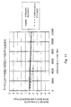
- Fig. 11 shows temporal changes in the power generation efficiency of the divided-chamber gas engine according to the working example and the power generation efficiency of the divided-chamber gas engine according to the comparative example.
- the vertical axis on which an initial-state power generation efficiency is indicated as 0 %, represents a power generation efficiency difference which is a rate of increase/decrease in the power generation efficiency from the initial-state power generation efficiency.
- the horizontal axis represents an operation time.
- Temporal changes in the power generation efficiency difference of the divided-chamber gas engine according to the working example are indicated in a solid line in the graph
- temporal changes in the power generation efficiency difference of the divided-chamber gas engine according to the comparative example are indicated in a chain line in the graph.
- the opening edge of each nozzle 9 at the auxiliary chamber 2 side has a chamfered shape.
- the structure, operation conditions, etc., of the divided-chamber gas engine according to the comparative example are the same as those of the divided-chamber gas engine according to the working example except that, in the divided-chamber gas engine according to the comparative example, the opening edge of each nozzle 9 at the auxiliary chamber 2 side has a corner. It is clear from the graph in Fig. 11 that the divided-chamber gas engine according to the comparative example exhibits degradation in the power generation efficiency difference three times or more faster than the divided-chamber gas engine according to the working example.
- the degradation, shown in the graph, in the power generation efficiency difference of the divided-chamber gas engine according to the comparative example is mainly caused by a change in the cross-sectional shape of the nozzles 9.
- the divided-chamber gas engine according to the comparative example exhibits a predetermined degree of degradation (-1 %) in the power generation efficiency difference relatively early. Accordingly, the auxiliary chamber forming body needs to be replaced relatively early.
- the auxiliary chamber forming body of the divided-chamber gas engine according to the working example is long-lived since the opening edge of each nozzle 9 at the auxiliary chamber 2 side has a chamfered shape.
- the present invention makes it possible to provide an efficient gas engine with reduced temporal degradation in performance. Moreover, in the divided-chamber gas engine according to the present invention, distortion in the shape of the nozzles' openings at the auxiliary chamber side is prevented, and thereby an occurrence of swirl flow is suppressed. As a result, decrease in the jet flame intensity is prevented, and thus effective energy utilization is realized.
Landscapes
- Engineering & Computer Science (AREA)
- Chemical & Material Sciences (AREA)
- Combustion & Propulsion (AREA)
- Mechanical Engineering (AREA)
- General Engineering & Computer Science (AREA)
- Combustion Methods Of Internal-Combustion Engines (AREA)
Applications Claiming Priority (2)
| Application Number | Priority Date | Filing Date | Title |
|---|---|---|---|
| JP2009297646 | 2009-12-28 | ||
| PCT/JP2010/007558 WO2011080917A1 (ja) | 2009-12-28 | 2010-12-27 | 副室式ガスエンジン |
Publications (2)
| Publication Number | Publication Date |
|---|---|
| EP2520780A1 true EP2520780A1 (de) | 2012-11-07 |
| EP2520780A4 EP2520780A4 (de) | 2013-07-24 |
Family
ID=44226341
Family Applications (1)
| Application Number | Title | Priority Date | Filing Date |
|---|---|---|---|
| EP10840776.8A Withdrawn EP2520780A4 (de) | 2009-12-28 | 2010-12-27 | Gasmotor mit hilfskammer |
Country Status (3)
| Country | Link |
|---|---|
| US (1) | US20130000598A1 (de) |
| EP (1) | EP2520780A4 (de) |
| WO (1) | WO2011080917A1 (de) |
Cited By (9)
| Publication number | Priority date | Publication date | Assignee | Title |
|---|---|---|---|---|
| EP2657479A1 (de) * | 2012-04-06 | 2013-10-30 | GE Jenbacher GmbH & Co OHG | Zylinderkopf für eine Brennkraftmaschine |
| WO2014094808A1 (en) | 2012-12-21 | 2014-06-26 | Caterpillar Energy Solutions Gmbh | Ignition plug tip of an internal combustion engine |
| WO2014114846A1 (en) * | 2013-01-22 | 2014-07-31 | Wärtsilä Finland Oy | Method for operating piston engine and piston engine |
| EP2998539A1 (de) * | 2014-09-19 | 2016-03-23 | Caterpillar Motoren GmbH & Co. KG | Zündungssystem für Verbrennungsmotoren |
| EP2971634A4 (de) * | 2013-03-15 | 2016-11-02 | Cummins Inc | Vorkammer einer brennkraftmaschine |
| EP3366900A4 (de) * | 2015-11-27 | 2018-08-29 | Mitsubishi Heavy Industries Engine & Turbocharger, Ltd. | Gasmotor |
| US10099581B2 (en) | 2015-04-28 | 2018-10-16 | Volvo Car Corporation | Support arrangement for a child seat |
| EP3536923A4 (de) * | 2016-12-08 | 2020-02-19 | Mitsubishi Heavy Industries Engine & Turbocharger, Ltd. | Gasmotor mit einer hilfskammer |
| US11261778B2 (en) | 2018-10-11 | 2022-03-01 | Scania Cv Ab | Pre-chamber arrangement for a gas engine and a gas engine |
Families Citing this family (18)
| Publication number | Priority date | Publication date | Assignee | Title |
|---|---|---|---|---|
| US9353674B2 (en) * | 2010-11-01 | 2016-05-31 | Mahle Powertrain, Llc | Turbulent jet ignition pre-chamber combustion system for spark ignition engines |
| US9476347B2 (en) | 2010-11-23 | 2016-10-25 | Woodward, Inc. | Controlled spark ignited flame kernel flow in fuel-fed prechambers |
| US8584648B2 (en) | 2010-11-23 | 2013-11-19 | Woodward, Inc. | Controlled spark ignited flame kernel flow |
| US9172217B2 (en) | 2010-11-23 | 2015-10-27 | Woodward, Inc. | Pre-chamber spark plug with tubular electrode and method of manufacturing same |
| JP6076662B2 (ja) * | 2012-09-20 | 2017-02-08 | 三菱重工業株式会社 | 副室式ガスエンジン |
| US9856848B2 (en) | 2013-01-08 | 2018-01-02 | Woodward, Inc. | Quiescent chamber hot gas igniter |
| US9765682B2 (en) | 2013-06-10 | 2017-09-19 | Woodward, Inc. | Multi-chamber igniter |
| US9556844B2 (en) | 2015-02-13 | 2017-01-31 | Caterpillar Inc. | Nozzle with contoured orifice surface and method of making same |
| US9653886B2 (en) | 2015-03-20 | 2017-05-16 | Woodward, Inc. | Cap shielded ignition system |
| US9840963B2 (en) | 2015-03-20 | 2017-12-12 | Woodward, Inc. | Parallel prechamber ignition system |
| CN114439600A (zh) | 2015-10-08 | 2022-05-06 | 康明斯公司 | 预燃室组件 |
| US9890689B2 (en) * | 2015-10-29 | 2018-02-13 | Woodward, Inc. | Gaseous fuel combustion |
| JP6047217B1 (ja) * | 2015-11-10 | 2016-12-21 | 川崎重工業株式会社 | ガスエンジン駆動システム |
| US10598079B2 (en) | 2015-11-11 | 2020-03-24 | Cummins Inc. | Charge-fed pre-chamber assembly |
| US10208651B2 (en) * | 2016-02-06 | 2019-02-19 | Prometheus Applied Technologies, Llc | Lean-burn pre-combustion chamber |
| JP6796471B2 (ja) * | 2016-12-08 | 2020-12-09 | 三菱重工エンジン&ターボチャージャ株式会社 | 副室式ガスエンジン |
| JP7002272B2 (ja) | 2017-09-29 | 2022-02-04 | 三菱重工エンジン&ターボチャージャ株式会社 | 副室式ガスエンジン |
| US11352968B1 (en) * | 2021-06-29 | 2022-06-07 | Ford Global Technologies, Llc | Methods and systems for reducing catalyst cooling during fuel cut via pre-chamber ignition system |
Family Cites Families (15)
| Publication number | Priority date | Publication date | Assignee | Title |
|---|---|---|---|---|
| US2893360A (en) * | 1957-10-23 | 1959-07-07 | Muller Klaus | Internal combustion engine |
| JPS5377909A (en) * | 1976-12-21 | 1978-07-10 | Toyota Motor Corp | Internal combustion engine equipped with supplementary combustion chamber |
| JPS5496614A (en) * | 1978-01-13 | 1979-07-31 | Isuzu Motors Ltd | Voltex flow type conbustion chamber |
| DE2831452A1 (de) * | 1978-07-18 | 1980-01-31 | Bosch Gmbh Robert | Brennkraftmaschine mit einem hauptbrennraum und einer in eine zuendkammer eingesetzten zuendeinrichtung |
| US4292935A (en) * | 1980-03-31 | 1981-10-06 | Rockwell International Corporation | Low nitrous oxide (NOX) precombustor |
| DE3123398C2 (de) * | 1981-06-12 | 1985-04-25 | MTU Motoren- und Turbinen-Union München GmbH, 8000 München | Vorbrennkammer für Dieselmaschinen |
| US4646695A (en) * | 1985-12-09 | 1987-03-03 | Oak Ridge Systems, Inc. | Device for improving the ignition of fuel-air mixtures in internal combustion engines |
| JPH0826769B2 (ja) | 1989-08-09 | 1996-03-21 | 株式会社クボタ | デイーゼルエンジンの渦流室式燃焼室の噴口 |
| WO1991012418A1 (en) | 1990-02-06 | 1991-08-22 | Caterpillar Inc. | Fuel combustion system, method, and nozzle member therefor |
| US5024193A (en) * | 1990-02-06 | 1991-06-18 | Caterpillar Inc. | Fuel combustion system, method, and nozzle member therefor |
| JP3872704B2 (ja) * | 2002-03-04 | 2007-01-24 | 三菱重工業株式会社 | 燃料噴射弁冷却構造 |
| US7066137B1 (en) * | 2003-11-03 | 2006-06-27 | Dawson Ralph E | Anti detonation device and method for internal combustion engines |
| DE102004023409B4 (de) * | 2004-05-12 | 2007-05-16 | Gottfried Schubert | Hochverdichtender Ottoverbrennungsmotor mit Drosselregelung, Fremdzündung und Kraftstoffdirekteinspritzung in eine Vorbrennkammer |
| JP2007113536A (ja) * | 2005-10-24 | 2007-05-10 | Nissan Motor Co Ltd | 副室式内燃機関 |
| DE102010029382A1 (de) * | 2010-05-27 | 2011-12-01 | Robert Bosch Gmbh | Laserinduzierte Fremdzündung für eine Brennkraftmaschine |
-
2010
- 2010-12-27 EP EP10840776.8A patent/EP2520780A4/de not_active Withdrawn
- 2010-12-27 WO PCT/JP2010/007558 patent/WO2011080917A1/ja not_active Ceased
- 2010-12-27 US US13/519,732 patent/US20130000598A1/en not_active Abandoned
Cited By (16)
| Publication number | Priority date | Publication date | Assignee | Title |
|---|---|---|---|---|
| EP2657479A1 (de) * | 2012-04-06 | 2013-10-30 | GE Jenbacher GmbH & Co OHG | Zylinderkopf für eine Brennkraftmaschine |
| EP2935865B1 (de) * | 2012-12-21 | 2020-06-24 | Caterpillar Energy Solutions GmbH | Zündkerzespitze eines verbrennungsmotors |
| WO2014094808A1 (en) | 2012-12-21 | 2014-06-26 | Caterpillar Energy Solutions Gmbh | Ignition plug tip of an internal combustion engine |
| WO2014114846A1 (en) * | 2013-01-22 | 2014-07-31 | Wärtsilä Finland Oy | Method for operating piston engine and piston engine |
| EP2971634A4 (de) * | 2013-03-15 | 2016-11-02 | Cummins Inc | Vorkammer einer brennkraftmaschine |
| US9797296B2 (en) | 2013-03-15 | 2017-10-24 | Cummins Inc. | Pre-chamber for internal combustion engine |
| EP2998539A1 (de) * | 2014-09-19 | 2016-03-23 | Caterpillar Motoren GmbH & Co. KG | Zündungssystem für Verbrennungsmotoren |
| WO2016041613A1 (en) * | 2014-09-19 | 2016-03-24 | Caterpillar Motoren Gmbh & Co. Kg | Ignition system for internal combustion engines |
| US10047688B2 (en) | 2014-09-19 | 2018-08-14 | Caterpillar Motoren Gmbh & Co. Kg | Ignition system for internal combustion engines |
| US10099581B2 (en) | 2015-04-28 | 2018-10-16 | Volvo Car Corporation | Support arrangement for a child seat |
| EP3366900A4 (de) * | 2015-11-27 | 2018-08-29 | Mitsubishi Heavy Industries Engine & Turbocharger, Ltd. | Gasmotor |
| EP3536923A4 (de) * | 2016-12-08 | 2020-02-19 | Mitsubishi Heavy Industries Engine & Turbocharger, Ltd. | Gasmotor mit einer hilfskammer |
| US11143092B2 (en) | 2016-12-08 | 2021-10-12 | Mitsubishi Heavy Industries Engine & Turbocharger, Ltd. | Precombustion chamber gas engine |
| US11566559B2 (en) | 2016-12-08 | 2023-01-31 | Mitsubishi Heavy Industries Engine & Turbocharger, Ltd. | Precombustion chamber gas engine |
| US11261778B2 (en) | 2018-10-11 | 2022-03-01 | Scania Cv Ab | Pre-chamber arrangement for a gas engine and a gas engine |
| US11608772B2 (en) | 2018-10-11 | 2023-03-21 | Scania Cv Ab | Pre-chamber arrangement for a gas engine and a gas engine |
Also Published As
| Publication number | Publication date |
|---|---|
| WO2011080917A1 (ja) | 2011-07-07 |
| US20130000598A1 (en) | 2013-01-03 |
| EP2520780A4 (de) | 2013-07-24 |
Similar Documents
| Publication | Publication Date | Title |
|---|---|---|
| US20130000598A1 (en) | Divided-chamber gas engine | |
| KR101625837B1 (ko) | 프리-챔버 장치 | |
| US10968814B2 (en) | Internal combustion engine for a motor vehicle | |
| KR20140025279A (ko) | 내연기관의 예연소실 및 그 작동 방법 | |
| CN111206984B (zh) | 带副室内燃机 | |
| CN105518274A (zh) | 用于以气体为燃料的内燃机的燃烧系统 | |
| CN111206983B (zh) | 带副室内燃机 | |
| JP2012137083A (ja) | 副室式ガスエンジン | |
| US8413446B2 (en) | Fuel injector arrangement having porous premixing chamber | |
| KR102081463B1 (ko) | 가스 연료로 작동되는 내연기관의 가스 혼합물을 점화하기 위한 점화 장치 | |
| CN114109587B (zh) | 燃烧装置及系统 | |
| EP3536925A1 (de) | Unterkammergasmotor | |
| JP5325020B2 (ja) | 副室式エンジン | |
| JP2008280922A (ja) | 副室式エンジン | |
| EP2520781B1 (de) | Verbrennungskammer für einen grossen gasmotor | |
| CN114233465B (zh) | 氨燃料燃烧系统、发动机及燃烧控制方法 | |
| JPH07269353A (ja) | ディーゼルエンジンの燃焼室構造 | |
| EP4368821A1 (de) | Wasserstoffmotor | |
| CN116927939A (zh) | 预燃烧室系统、点火装置及发动机 | |
| JP2005090381A (ja) | パイロット油着火ガスエンジン | |
| JP2007255313A (ja) | 副室式エンジン | |
| JP7585986B2 (ja) | 内燃機関用のスパークプラグ及びこれを備えた内燃機関 | |
| JP7600717B2 (ja) | 内燃機関用のスパークプラグ | |
| AU2022231769B2 (en) | Engine mixing structures | |
| JP4394974B2 (ja) | 気体燃料を筒内噴射する内燃機関と内燃機関の点火方法 |
Legal Events
| Date | Code | Title | Description |
|---|---|---|---|
| PUAI | Public reference made under article 153(3) epc to a published international application that has entered the european phase |
Free format text: ORIGINAL CODE: 0009012 |
|
| 17P | Request for examination filed |
Effective date: 20120717 |
|
| AK | Designated contracting states |
Kind code of ref document: A1 Designated state(s): AL AT BE BG CH CY CZ DE DK EE ES FI FR GB GR HR HU IE IS IT LI LT LU LV MC MK MT NL NO PL PT RO RS SE SI SK SM TR |
|
| DAX | Request for extension of the european patent (deleted) | ||
| A4 | Supplementary search report drawn up and despatched |
Effective date: 20130625 |
|
| RIC1 | Information provided on ipc code assigned before grant |
Ipc: F02B 19/16 20060101AFI20130619BHEP Ipc: F02B 19/10 20060101ALI20130619BHEP Ipc: F02B 19/18 20060101ALI20130619BHEP |
|
| 17Q | First examination report despatched |
Effective date: 20141119 |
|
| STAA | Information on the status of an ep patent application or granted ep patent |
Free format text: STATUS: THE APPLICATION IS DEEMED TO BE WITHDRAWN |
|
| 18D | Application deemed to be withdrawn |
Effective date: 20150331 |