EP2935865B1 - Zündkerzespitze eines verbrennungsmotors - Google Patents
Zündkerzespitze eines verbrennungsmotors Download PDFInfo
- Publication number
- EP2935865B1 EP2935865B1 EP12818487.6A EP12818487A EP2935865B1 EP 2935865 B1 EP2935865 B1 EP 2935865B1 EP 12818487 A EP12818487 A EP 12818487A EP 2935865 B1 EP2935865 B1 EP 2935865B1
- Authority
- EP
- European Patent Office
- Prior art keywords
- ignition plug
- combustion chamber
- flow channel
- plug tip
- funnel
- Prior art date
- Legal status (The legal status is an assumption and is not a legal conclusion. Google has not performed a legal analysis and makes no representation as to the accuracy of the status listed.)
- Active
Links
Images

Classifications
-
- F—MECHANICAL ENGINEERING; LIGHTING; HEATING; WEAPONS; BLASTING
- F02—COMBUSTION ENGINES; HOT-GAS OR COMBUSTION-PRODUCT ENGINE PLANTS
- F02B—INTERNAL-COMBUSTION PISTON ENGINES; COMBUSTION ENGINES IN GENERAL
- F02B19/00—Engines characterised by precombustion chambers
- F02B19/16—Chamber shapes or constructions not specific to sub-groups F02B19/02 - F02B19/10
- F02B19/18—Transfer passages between chamber and cylinder
-
- F—MECHANICAL ENGINEERING; LIGHTING; HEATING; WEAPONS; BLASTING
- F02—COMBUSTION ENGINES; HOT-GAS OR COMBUSTION-PRODUCT ENGINE PLANTS
- F02P—IGNITION, OTHER THAN COMPRESSION IGNITION, FOR INTERNAL-COMBUSTION ENGINES; TESTING OF IGNITION TIMING IN COMPRESSION-IGNITION ENGINES
- F02P13/00—Sparking plugs structurally combined with other parts of internal-combustion engines
-
- Y—GENERAL TAGGING OF NEW TECHNOLOGICAL DEVELOPMENTS; GENERAL TAGGING OF CROSS-SECTIONAL TECHNOLOGIES SPANNING OVER SEVERAL SECTIONS OF THE IPC; TECHNICAL SUBJECTS COVERED BY FORMER USPC CROSS-REFERENCE ART COLLECTIONS [XRACs] AND DIGESTS
- Y02—TECHNOLOGIES OR APPLICATIONS FOR MITIGATION OR ADAPTATION AGAINST CLIMATE CHANGE
- Y02T—CLIMATE CHANGE MITIGATION TECHNOLOGIES RELATED TO TRANSPORTATION
- Y02T10/00—Road transport of goods or passengers
- Y02T10/10—Internal combustion engine [ICE] based vehicles
- Y02T10/12—Improving ICE efficiencies
Definitions
- the present disclosure generally relates to an ignition plug tip of an ignition plug of an internal combustion engine and, more particular, to an ignition plug tip of a gaseous fuel internal combustion engine comprising a pre-combustion chamber.
- an ignition plug including a pre-combustion chamber in some internal combustion engine applications, such as gaseous fuel applications.
- a pre-combustion chamber is a relatively small gas accumulating chamber located in the engine cylinder head.
- the pre-combustion chamber is in fluid communication with the main combustion chamber of the engine via a number of small flow channels.
- a spark plug ignites gaseous fuel within the pre-combustion chamber (as opposed to igniting the gaseous fuel in the main combustion chamber). Ignition of the gaseous fuel in the pre-combustion chamber generates a front of burning fuel which is jetted or otherwise advanced through the flow channels into the main combustion chamber thereby igniting the mixture of gaseous fuel and air therein.
- EP 2 520 780 A1 discloses an auxiliary chamber-type gas engine comprises a plurality of nozzles through which the auxiliary chamber and the main combustion chamber are in fluid communication with each other. It is further disclosed that an opening edge at the auxiliary combustion chamber side of each of the plurality of nozzles is formed to have a curved surface for making it possible to maintain stable combustion in the main combustion chamber while preventing degradation in combustion performance.
- WO 91/12418 A1 shows a precombustion chamber assembly defining a prechamber having a preselected shape and volume and includes a plurality of ejection passages extending radially outwardly such that burning gases are funneled radially outwardly through the plurality of ejection passages.
- the present disclosure is directed, at least in part, to improving or overcoming one or more aspects of prior systems.
- an ignition plug tip of an ignition plug is configured to be used in an internal combustion engine including at least one main combustion chamber.
- the disclosed ignition plug tip comprises a nozzle portion forming at least a portion of a pre-combustion chamber and having an inner surface.
- At least one flow channel is configured to fluidly connect the pre-combustion chamber to the main combustion chamber.
- the at least one flow channel extends tangentially with respect to a center axis of the nozzle portion such that a swirl of the combustion mixture within the main combustion chamber is increased.
- the at least one flow channel includes a main portion having constant cross-section and a funnel-shaped inlet portion at the inner surface.
- the funnel-shaped inlet portion has a length of about 30 % to 70 % the length of the at least one flow channel.
- an internal combustion engine may comprise at least one cylinder defining at least a portion of a main combustion chamber, a cylinder head configured to form at least a portion of the main combustion chamber, and at least one ignition plug according to the present disclosure attached to the cylinder head, wherein the ignition plug tip at least partially extends into the main combustion chamber and is in fluid communication with the main combustion chamber via the at least one flow channel.
- the diameter of the funnel-shaped inlet portion at the inner surface is greater than the diameter of the main portion.
- the at least one flow channel may comprise a funnel-shaped outlet at an outer surface of the nozzle portion.
- the outer surface may extend at least partially into the main combustion chamber.
- the funnel-shaped outlet opens in a direction towards the outer surface, such that the diameter of the outlet is greater than the constant cross-section of the main portion of the flow channel.
- the funnel-shaped inlet portion may further comprise a rounded or chamfered edge at the inner surface.
- the funnel-shaped outlet may be constituted by a rounding or a chamfer.
- the present disclosure may be based in part on the realization that providing an inlet portion of a flow channel of an ignition plug tip of an ignition plug in a funnel-like shape may support in, due to the decreasing cross-section, accelerating the burning fuel, stabilizing the transition of the burning fuel from the pre-combustion chamber into the main combustion chamber, and stabilizing the combustion within the main combustion chamber.
- By further providing an opening edge of the funnel-shaped inlet portion at the pre-combustion chamber side may smooth the transition from the pre-combustion chamber into the flow channel, which may further increase the velocity of the burning fuel and decrease any loss of kinetic energy of the burning fuel.
- the present disclosure may be further based in part on the realization that providing the outlet of the flow channel of the ignition plug tip in a funnel-like shape may have an improved and steady transition in velocity of the burning fuel extending out of the flow channel.
- An acceleration of the burning fuel within the flow channel and a smooth transition of the effective cross-section of the flow channel may cause a smooth transition of the velocity of the burning fuel when extending out of the flow channel into the main combustion chamber, such that the burning fuel in the form of torches may reach the entire space of the main combustion chamber, which leads to a high efficient combustion and increases the efficiency of the internal combustion engine.
- the internal combustion engine 10 may include features not shown, such as fuel systems, air systems, cooling systems, peripheries, drivetrain components, turbochargers, etc.
- the internal combustion engine 10 is considered a four-stroke gaseous fuel internal combustion engine.
- the gaseous fuel internal combustion engine 10 may be any type of engine (turbine, gas, diesel, natural gas, propane, two-stroke, etc.) that would utilize an ignition plug having an integrated pre-combustion chamber.
- the internal combustion engine 10 may be of any size, with any number of cylinders, and in any configuration ("V," in-line, radial, etc.).
- the internal combustion engine 10 may be used to power any machine or other device, including locomotive applications, on-highway trucks or vehicles, off-highway trucks or machines, earth moving equipment, generators, aerospace applications, marine applications, pumps, stationary equipment, or other engine powered applications.
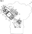
- the internal combustion engine 10 includes an engine block 12 having a plurality of cylinders 14 (one of which is illustrated in Fig. 1 ).
- a piston 16 is slidably disposed within the cylinder 14 to reciprocate between a top-dead-center position and a bottom-dead-center position.
- a connecting rod 18 connects the piston 16 to an eccentric crankpin 20 of a crankshaft 22 such that reciprocating motion of the piston results in rotation of the crankshaft 22.
- the internal combustion engine 10 also includes a cylinder head 24 engaged with the engine block 12 to cover the cylinder 14, thereby defining a main combustion chamber 26.
- the cylinder head 24 defines intake and exhaust openings 28 that allow intake gases into the main combustion chamber 26 and exhaust gases out of the main combustion chamber 26, respectively.
- the engine valves 30 are positioned to selectively open and close the openings 28.
- Each cylinder 14 includes multiple intake and exhaust openings 28.
- the internal combustion engine 10 includes a series of valve actuation assemblies 40 (one of which is illustrated in Fig. 1 ).
- the multiple valve actuation assemblies 40 are provided per cylinder 14.
- one valve actuation assembly may be used to open and close the intake valves and another valve actuation assembly may be provided to open and close the exhaust valves.
- the valve actuation assembly 40 includes a rocker arm 46.
- the rocker arm 46 is pivotally mounted in the cylinder head 24 and attaches to the engine valves 30 at one end and attaches to a push rod 48 at the other end. Oscillation of the rocker arm 46 about its pivot point 50 causes the valves 30 to move between an open position and a closed position.
- the valve actuation assembly 40 also includes valve springs 52 that bias the valves 30 toward the closed position (i.e. closing the intake and exhaust openings 28).
- camshaft 56 operatively engages the crankshaft 22.
- the camshaft 56 is connected with crankshaft 22 in any manner readily apparent to one skilled in the art where rotation of the crankshaft 22 results in rotation of the camshaft 56.
- camshaft 56 may be connected to crankshaft 22 through a gear train (not shown).
- a first cam lobe 58 is disposed on the camshaft 56 to engage the lifter 54.
- the camshaft 56 may include additional cam lobes to engage with other lifters in order to actuate additional engine valves.
- the internal combustion engine 10 also includes an ignition plug 60 having a pre-combustion chamber.
- the ignition plug 60 is positioned within the cylinder head 24 between the valves 30.
- the ignition plug 60 may be configured in a variety of ways. Any assembly capable of being positioned in the cylinder head 24 to support a combustion event outside of the main combustion chamber 26, and direct the combustion into the main combustion chamber 26 may be used.
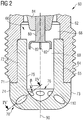
- the ignition plug 60 of Fig. 1 includes an ignition plug main body 62 and an ignition plug tip 70 attached to the ignition plug main body 62.
- the ignition plug main body 62 includes a threaded portion 64 configured to engage with a threaded portion of the cylinder head 24 (see Fig. 1 ).
- Both the ignition plug main body 62 and the ignition plug tip 70 may be formed by casting.
- the ignition plug tip 70 may be formed by metal sintering and may consist of a material having a high thermal and mechanical stress resistance, such as, for example, a chrome-nickel alloy.
- the ignition plug tip 70 may consist of LC-NI 99 having the material number 2.4068.
- the ignition plug main body 62 and the ignition plug tip 70 are disposed about a center axis 90 and include a substantially cylindrical cross-section.
- the ignition plug main body 62 defines a first portion 68 of a pre-combustion chamber 66.
- the ignition plug tip 70 defines a second portion 69 of the pre-combustion chamber 66.
- the first portion 68 and the second portion 69 are in fluid communication with each other.
- a sealing mechanism (not shown in the drawings) may be provided at the first portion 68 of the pre-combustion chamber 66 for sealing the pre-combustion chamber 66 with respect to the upper portion of the pre-combustion chamber 66.
- At least one electrode 80 extends along the center axis 90 and includes at least one electrode end 82 at least partially extending into the first and second portions 68, 69 of the pre-combustion chamber 66.
- the at least one electrode 80 may be electrically connected to an engine control unit (not shown) and may be configured to generate a spark at the at least one electrode end 82 upon a signal provided by the engine control unit.
- the at least one electrode 80 is supported by an insulator 84, such as, for example, a ceramic material.
- the ignition plug tip 70 comprises a connecting portion 72 and a nozzle portion 74.
- the connecting portion 72 is configured to be inserted into a receiving portion 65 of the ignition plug main body 62.
- the connecting portion 72 and the receiving portion 65 have a cylindrical shape substantially corresponding to each other, such that the connecting portion 72 of the ignition plug tip 70 at least partially form-fits into the receiving portion 65 of the ignition plug main body 72.
- the ignition plug tip 70 is fixedly attached to the ignition plug main body 62 by means of welding, such as, for example, laser beam welding. It is understood that the beam weld circumferentially extends around the entire flange formed between the bottom end of the ignition tip main body 62 and a shoulder 71 of the nozzle portion 74 of the ignition plug tip 70.
- the ignition plug tip 70 may be fixedly attached to the ignition plug main body 62 by means of, for instance, soldering or any other suitable means.
- the ignition plug tip 70 may be removably attached to the ignition plug main body 62 by means of, for instance, snap fit, pressure fit, or any other suitable means. In such embodiments, for example, after a predetermined operation time of the ignition plug 60 or in the case of wear of the ignition plug tip 70, the ignition plug tip 70 may be replaced by a new ignition plug tip.
- the ignition plug tip 70 comprises an inner surface 75 forming the second portion 69 of the pre-combustion chamber 66.
- the inner surface 75 includes a bottom portion 76 having a generally convex funnel-like shape. It is preferred that the bottom portion 76 is cup-like shaped having a convex form.
- the ignition plug tip 70 includes an outer surface 73 configured to at least partially extend into the main combustion chamber 26 of the internal combustion engine 10.
- the ignition plug tip 70 includes at least one flow channel 110 disposed at the nozzle portion 74.
- the at least one flow channel 110 is configured to fluidly connect the pre-combustion chamber 66 with the main combustion chamber 26 (see Fig. 1 ). It is further preferred that the at least one flow channel 110 fluidly connects the pre-combustion chamber 66 at the bottom portion 76 with the main combustion chamber 26.
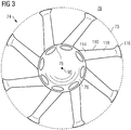
- the nozzle portion 74 of the ignition plug tip 70 is shown in greater detail. Particularly, a top view of the nozzle portion 74 of the ignition plug tip 70 of Fig. 2 is illustrated in Fig. 3 . Fig. 4 shows a cut view taken along line IV - IV of Fig. 2 . As illustrated in Fig 3 , the ignition plug tip 70 includes eight flow channels. In some other embodiments, the ignition plug tip 70 may include more or less than eight flow channels. The illustration of Fig. 3 shows the nozzle portion 74 and the eight flow channels in a revealed manner, such that an exact expansion of the flow channels is shown in greater detail.
- each of the other illustrated flow channels of the ignition plug tip 70 may also comprise the same technical features and aspects described with reference to the flow channel 110.
- Each of the at least one flow channel 110 comprises a funnel shaped inlet portion 114 disposed at the inner surface 75 of the nozzle portion 74 and an outlet 116 disposed at the outer surface 73 of the nozzle portion 74.
- the at least one flow channel 110 further comprises a main portion 118 configured to fluidly connect the inlet portion 114 with the outlet 116.
- the main portion 118 includes a length b and has a substantially constant cross-section.
- the main portion 118 comprises a constant cross-section in the shape of a circle, an oval, a rectangle, or any other suitable cross-sectional shape.
- the funnel-shaped inlet portion 114 has a length a of about 30 % to 70 %, preferably about 40 % to 60 % the length of the entire flow channel 110.
- the length of a flow channel 110 may be the length c of a center axis L of the flow channel 110, wherein the length c of the center axis L may be constituted by the length a of the inlet portion 114 plus the length b of the main portion 118, such that the length c extends from the opening edge of the inlet portion 114 at the inner surface 75 to the outlet 116 at the outer surface 73.
- the funnel-shaped inlet portion 114 has an opening angle ⁇ of, for example, about 1° to 5°, preferably 1° to 3° with respect to the center axis L of the flow channel 110, such that the diameter of the funnel shaped inlet portion 114 at the inner surface 75 is greater than the constant diameter of the main portion 118.
- the outlet 116 is also funnel-shaped, such that the cross-sectional diameter of the outlet 116 is greater than the constant cross-sectional diameter of the main portion 118.
- the funnel-shaped outlet 116 may comprise a rounding.
- the funnel-shaped outlet 116 may comprises a chamfer. It should be noted that the length of the funnel shaped outlet 116 is much smaller than the length a of the funnel-shaped inlet portion 114.
- the main portion 118 may comprise a constant cross-sectional diameter of about 0.6 to 2.0 mm.
- the outlet 116 may comprise a cross-sectional diameter being about 5 to 20 %, preferably about 10 to 15 % greater than the cross-sectional diameter of the main portion 118.
- the rounding of the outlet 116 may be in a range from about R0.1 to R0.5.
- the cross-sectional diameter of the outlet may comprise, for instance, about 1.1 to 1.2 mm, such that a chamfer of, for example, 0.1 x 0.1 is provided.
- the funnel-shaped inlet portion 114 may comprise an opening angle ⁇ of about 2° with respect to the center axis L of the flow channel 110, and a length a of about 2.0 mm.
- the main portion 118 may comprise a length b of about 2.0 mm, such that the entire flow channel 110 comprises a length c of about 4.0 mm.
- the length a of the funnel-shaped inlet portion 114 is about 50 % the length c of the flow channel 110.
- the rounding of the opening edge at the inner surface 75 may be in a range from about R0.1 to R0.5.
- the cross-sectional diameter of the opening edge may comprise, for instance, about 1.1 to 1.2 mm, such that a chamfer of, for example, 0.1 x 0.1 is provided.
- the funnel-shaped inlet portion 114 comprises a cross-sectional diameter at the inner surface 75 being greater than the constant cross-sectional diameter of the main portion 118.
- the diameter of the funnel-shaped inlet portion114 at the inner surface 75 may be about 5 to 20 %, preferably about 10 to 15 % greater than the constant cross-sectional diameter of the main portion 118 of the at least one fuel channel 110.
- transitioning portion between, for example, the inlet portion 114 and the main portion 118 may be also rounded, such that the burning fuel flow is further optimized.
- transitioning portion between the outlet 116 and the main portion 118 may also be rounded.
- the at least one flow channel 110 extends tangentially with respect to the center axis 90.
- the tangentially angle between two adjacent flow channels 110 may be, for example, in the range from about 35° to 45°.
- the tangentially flow channel 110 may support in having a better transition of the burning fuel from the pre-combustion chamber 69 into the flow channel.
- the tangentially flow channel 110 is arranged in a manner such that a swirl of the combustion mixture within the main combustion chamber 26 may be increased.
- the exemplary disclosed ignition plug tip 70 may further include at least one further flow channel comprising the same technical features as described with respect to the at least one flow channel 110.
- the inlet and the outlet of the at least one further flow channel may be arranged at a higher level with respect to the center axis 90 than the at least one flow channel 110.
- the at least one flow channel 110 is disposed at a first axial position with respect to the center axis 90, and the at least one further flow channel 110 is disposed at a second axial position being different to the first axial position. This may ensure that the nozzle portion 74 can be provided with more flow channels for providing a better transition from the pre-combustion chamber 66 into the main combustion chamber 26.
- outlets of the flow channels may be distributed azimuthically with respect to the center axis 90. This may further support in ensuring a uniform distribution of the burning fuel from the pre-combustion chamber 66 into the main combustion chamber 26.
- the at least one flow channel 110 may extend obliquely downward from pre-combustion chamber 69 to the main combustion chamber 26, such that the opening edge of the inlet portion 114 may be disposed at a higher level than the outlet 116.
- the center axis L of the at least one flow channel 110 may form an angle ⁇ with a horizontal axis in a range from, for example, about 5° to 20°, preferably 5° to 10°.
- a mixture of gaseous fuel and air may be supplied into the main combustion chamber 26 via the intake opening 28. Subsequently the intake opening 28 closes the supply of the mixture of gaseous fuel and air to the main combustion chamber 26 and the compression stroke may start.
- the piston 16 compresses the mixture of gaseous fuel and air to a predetermined pressure. During such compression, at least some of the mixture of gaseous fuel and air may be pushed from the main combustion chamber 26 into the pre-combustion chamber 66 disposed within the ignition plug 60 and the ignition plug tip 70 via the at least one flow channel 110.
- an electronic control unit may provide a signal to the ignition plug 60, specifically to the at least one electrode 80 for generating a spark within the pre-combustion chamber 66.
- the spark is configured to ignite the mixture of gaseous fuel and air within the pre-combustion chamber.
- the ignited mixture may then expand out of the pre-combustion chamber 66 through the at least one flow channel 110 into the main combustion chamber in form of torches, which may then, in turn, ignite the mixture of gaseous fuel and air within the main combustion chamber 26.
- the change in velocity of the burning fuel which is based on the continuation equation, may be smoothly.
- the burning fuel expanding in the form of torches through the at least one flow channel 110 may reach into the entire main combustion chamber 26, such that the approximately the entire amount of the mixture of gaseous fuel and air may be ignited.
Landscapes
- Engineering & Computer Science (AREA)
- Chemical & Material Sciences (AREA)
- Combustion & Propulsion (AREA)
- Mechanical Engineering (AREA)
- General Engineering & Computer Science (AREA)
- Combustion Methods Of Internal-Combustion Engines (AREA)
Claims (14)
- Zündkerzenspitze (70) einer Zündkerze (60), die dazu konfiguriert ist, in einer Brennkraftmaschine (10) verwendet zu werden, einschließlich mindestens einer Hauptbrennkammer (26), wobei die Zündkerzenspitze (70) umfasst:einen Düsenabschnitt (74), der zumindest einen Abschnitt einer Vorbrennkammer (66) bildet und eine Innenoberfläche (75) aufweist; undmindestens einen Strömungskanal (110), der dazu konfiguriert ist, die Vorbrennkammer (66) fluidisch mit der Hauptbrennkammer (26) zu verbinden, wobei der mindestens eine Strömungskanal (110) einen Hauptabschnitt (118) einschließt, der einen konstanten Querschnitt und einen trichterförmigen Einlassabschnitt (114) an der Innenoberfläche (75) aufweist, und dadurch gekennzeichnet, dass sich der mindestens eine Strömungskanal (110) tangential in Bezug auf eine Mittelachse (90) des Düsenabschnitts (74) erstreckt, sodass eine Verwirbelung des Verbrennungsgemisches innerhalb der Hauptbrennkammer (26) erhöht wird, und der trichterförmige Einlassabschnitt (114) eine Länge (a) von etwa 30 % bis 70 % der Länge (c) des mindestens einen Strömungskanals (110) aufweist.
- Zündkerzenspitze (70) nach Anspruch 1, wobei sich der trichterförmige Einlassabschnitt (114) in eine Richtung der Innenoberfläche (75) öffnet.
- Zündkerzenspitze (70) nach einem der Ansprüche 1 oder 2, wobei der trichterförmige Einlassabschnitt (114) eine abgerundete Kante an der Innenoberfläche (75) einschließt.
- Zündkerzenspitze (70) nach einem der Ansprüche 1 oder 2, wobei der trichterförmige Einlassabschnitt (114) eine abgeschrägte Kante an der Innenoberfläche (75) einschließt.
- Zündkerzenspitze (70) nach einem der vorstehenden Ansprüche, wobei
der Düsenabschnitt (74) ferner eine Außenoberfläche (73) einschließt, die dazu konfiguriert ist, sich mindestens teilweise in die Hauptbrennkammer (26) zu erstrecken, und
der mindestens eine Strömungskanal (110) ferner einen trichterförmigen Auslass (116) an der Außenoberfläche (73) einschließt. - Zündkerzenspitze (70) nach einem der vorstehenden Ansprüche, wobei die Innenoberfläche (75) einen unteren Abschnitt (76), aufweisend eine konvexe trichterartige Form einschließt.
- Zündkerzenspitze (70) nach einem der vorstehenden Ansprüche, wobei der trichterförmige Auslass (116) des mindestens einen Strömungskanals (110) azimutal in Bezug auf eine Mittelachse (90) des Düsenabschnitts (74) verteilt ist.
- Zündkerzenspitze (70) nach einem der vorstehenden Ansprüche, wobei sich der mindestens eine Strömungskanal (110) von der Innenoberfläche (75) zu der Außenoberfläche (75) schräg nach unten erstreckt.
- Zündkerzenspitze (70) nach einem der vorstehenden Ansprüche, ferner umfassend mindestens einen weiteren Strömungskanal (110), wobei der mindestens eine Strömungskanal (110) an einer ersten axialen Position in Bezug auf eine Mittelachse des Düsenabschnitts (74) angeordnet ist, und der mindestens eine weitere Strömungskanal (110) an einer zweiten axialen Position, die sich von der ersten axialen Position unterscheidet, angeordnet ist.
- Zündkerze (60), die dazu konfiguriert ist, in einer Brennkraftmaschine (10) verwendet zu werden, umfassend:einen Zündkerzenhauptkörper (62), der zumindest einen Abschnitt einer Vorbrennkammer (66) bildet; undeine Zündkerzenspitze (70) nach einem der vorstehenden Ansprüche, die an dem Zündkerzenhauptkörper (62) angebracht ist.
- Zündkerze (60) nach Anspruch 10, ferner umfassend mindestens eine Elektrode (80), die sich mindestens teilweise in die Vorbrennkammer (66) erstreckt.
- Zündkerze (60) nach einem der Ansprüche 10 oder 11, wobei der Zündkerzenhauptkörper (62) einen Gewindeabschnitt (64) einschließt, der dazu konfiguriert ist, in einen Zylinderkopf (24) der Brennkraftmaschine (10) einzugreifen.
- Zündkerze (60) nach einem der Ansprüche 10 bis 12, wobei die Zündkerzenspitze (70) an dem Zündkerzenhauptkörper (62) durch mindestens eines von einem Schweißen, Löten und/oder Druckanpassen angebracht ist.
- Brennkraftmaschine (10), umfassend:mindestens einen Zylinder (14), der zumindest einen Abschnitt einer Hauptbrennkammer (26) definiert;einen Zylinderkopf (24), der dazu konfiguriert ist, zumindest einen Abschnitt der Hauptbrennkammer (26) zu bilden; undmindestens eine Zündkerze (60) nach einem der Ansprüche 10 bis 13, die an dem Zylinderkopf (24) angebracht ist, wobei sich die Zündkerzenspitze (70) mindestens teilweise in die Hauptbrennkammer (26) erstreckt und mit der Hauptbrennkammer (26) über den mindestens einen Strömungskanal (110) in Fluidverbindung steht.
Applications Claiming Priority (1)
| Application Number | Priority Date | Filing Date | Title |
|---|---|---|---|
| PCT/EP2012/005352 WO2014094808A1 (en) | 2012-12-21 | 2012-12-21 | Ignition plug tip of an internal combustion engine |
Publications (2)
| Publication Number | Publication Date |
|---|---|
| EP2935865A1 EP2935865A1 (de) | 2015-10-28 |
| EP2935865B1 true EP2935865B1 (de) | 2020-06-24 |
Family
ID=47603527
Family Applications (1)
| Application Number | Title | Priority Date | Filing Date |
|---|---|---|---|
| EP12818487.6A Active EP2935865B1 (de) | 2012-12-21 | 2012-12-21 | Zündkerzespitze eines verbrennungsmotors |
Country Status (2)
| Country | Link |
|---|---|
| EP (1) | EP2935865B1 (de) |
| WO (1) | WO2014094808A1 (de) |
Families Citing this family (7)
| Publication number | Priority date | Publication date | Assignee | Title |
|---|---|---|---|---|
| US9797296B2 (en) | 2013-03-15 | 2017-10-24 | Cummins Inc. | Pre-chamber for internal combustion engine |
| US9739192B2 (en) | 2015-05-04 | 2017-08-22 | Caterpillar Inc. | Fuel combustion system, nozzle for prechamber assembly with curved orifices, and method of making same |
| EP3173596B1 (de) | 2015-11-25 | 2020-04-01 | Caterpillar Energy Solutions GmbH | Vorverbrennungskammeranordnung für verbrennungsmotoren |
| EP3181855B1 (de) * | 2015-12-14 | 2018-08-29 | Caterpillar Energy Solutions GmbH | Vorkammer eines verbrennungsmotors |
| GB2574201B (en) | 2018-05-28 | 2021-10-27 | Caterpillar Energy Solutions Gmbh | Pre-chamber body for an internal combustion engine |
| SE542877C2 (en) * | 2018-10-11 | 2020-07-28 | Scania Cv Ab | A pre-chamber arrangement for a gas engine and a gas engine |
| DE102021001691A1 (de) | 2021-03-31 | 2022-03-03 | Daimler Ag | Vorkammerzündkerze für eine Verbrennungskraftmaschine sowie Verbrennungskraftmaschine, insbesondere für ein Kraftfahrzeug |
Citations (3)
| Publication number | Priority date | Publication date | Assignee | Title |
|---|---|---|---|---|
| WO1991012418A1 (en) * | 1990-02-06 | 1991-08-22 | Caterpillar Inc. | Fuel combustion system, method, and nozzle member therefor |
| JP2007297942A (ja) * | 2006-04-28 | 2007-11-15 | Nissan Motor Co Ltd | 内燃機関の点火装置 |
| EP2520780A1 (de) * | 2009-12-28 | 2012-11-07 | Kawasaki Jukogyo Kabushiki Kaisha | Gasmotor mit hilfskammer |
Family Cites Families (3)
| Publication number | Priority date | Publication date | Assignee | Title |
|---|---|---|---|---|
| US3012085A (en) * | 1959-02-13 | 1961-12-05 | Harold D Regar | Spark plug assembly |
| US3066662A (en) * | 1960-08-26 | 1962-12-04 | Walker Mfg Co | Ignition device for internal combustion engines |
| JP5002566B2 (ja) * | 2008-10-16 | 2012-08-15 | 大阪瓦斯株式会社 | エンジン及びエンジン用点火プラグ |
-
2012
- 2012-12-21 EP EP12818487.6A patent/EP2935865B1/de active Active
- 2012-12-21 WO PCT/EP2012/005352 patent/WO2014094808A1/en not_active Ceased
Patent Citations (3)
| Publication number | Priority date | Publication date | Assignee | Title |
|---|---|---|---|---|
| WO1991012418A1 (en) * | 1990-02-06 | 1991-08-22 | Caterpillar Inc. | Fuel combustion system, method, and nozzle member therefor |
| JP2007297942A (ja) * | 2006-04-28 | 2007-11-15 | Nissan Motor Co Ltd | 内燃機関の点火装置 |
| EP2520780A1 (de) * | 2009-12-28 | 2012-11-07 | Kawasaki Jukogyo Kabushiki Kaisha | Gasmotor mit hilfskammer |
Also Published As
| Publication number | Publication date |
|---|---|
| EP2935865A1 (de) | 2015-10-28 |
| WO2014094808A1 (en) | 2014-06-26 |
Similar Documents
| Publication | Publication Date | Title |
|---|---|---|
| EP2700796B1 (de) | Vorbrennkammer für einen Verbrennungsmotor und Betriebsverfahren dafür | |
| EP2935865B1 (de) | Zündkerzespitze eines verbrennungsmotors | |
| EP3012431B1 (de) | Vorverbrennungskammeranordnung für Verbrennungsmotoren | |
| EP3118433B1 (de) | Vorkammeranordnung für verbrennungsmotoren | |
| CN111164285B (zh) | 用于机动车的内燃机 | |
| EP2573355B1 (de) | Vorverbrennungskammerspitze | |
| JP5002566B2 (ja) | エンジン及びエンジン用点火プラグ | |
| EP2520780A1 (de) | Gasmotor mit hilfskammer | |
| EP3051092A1 (de) | Kühlung der vorkammer in einem verbrennungsmotor | |
| WO2014177169A1 (en) | Method for manufacturing an ignition electrode | |
| WO2017171776A1 (en) | Internal combustion engine and method of igniting a fuel | |
| CN112065568B (zh) | 具有液压致动活塞的预燃室点火系统 | |
| JP3885071B2 (ja) | 水素エンジン | |
| EP2193263B1 (de) | Verbrennungsmotor | |
| GB2545479A (en) | Pre-combustion chamber | |
| US11994058B2 (en) | Ignition charge formation stabilization in gaseous fuel engine system | |
| CN119353092A (zh) | 二四冲程可变发动机 | |
| WO2024224808A1 (ja) | ガスエンジン | |
| JP2012149654A (ja) | エンジン及びエンジン用点火プラグ | |
| JP2022045147A (ja) | 点火装置を備えた2ストロークエンジン | |
| KR20140039784A (ko) | 내연기관용 실린더 |
Legal Events
| Date | Code | Title | Description |
|---|---|---|---|
| PUAI | Public reference made under article 153(3) epc to a published international application that has entered the european phase |
Free format text: ORIGINAL CODE: 0009012 |
|
| 17P | Request for examination filed |
Effective date: 20150618 |
|
| AK | Designated contracting states |
Kind code of ref document: A1 Designated state(s): AL AT BE BG CH CY CZ DE DK EE ES FI FR GB GR HR HU IE IS IT LI LT LU LV MC MK MT NL NO PL PT RO RS SE SI SK SM TR |
|
| AX | Request for extension of the european patent |
Extension state: BA ME |
|
| DAX | Request for extension of the european patent (deleted) | ||
| STAA | Information on the status of an ep patent application or granted ep patent |
Free format text: STATUS: EXAMINATION IS IN PROGRESS |
|
| 17Q | First examination report despatched |
Effective date: 20190313 |
|
| GRAP | Despatch of communication of intention to grant a patent |
Free format text: ORIGINAL CODE: EPIDOSNIGR1 |
|
| STAA | Information on the status of an ep patent application or granted ep patent |
Free format text: STATUS: GRANT OF PATENT IS INTENDED |
|
| INTG | Intention to grant announced |
Effective date: 20200107 |
|
| GRAS | Grant fee paid |
Free format text: ORIGINAL CODE: EPIDOSNIGR3 |
|
| GRAA | (expected) grant |
Free format text: ORIGINAL CODE: 0009210 |
|
| STAA | Information on the status of an ep patent application or granted ep patent |
Free format text: STATUS: THE PATENT HAS BEEN GRANTED |
|
| AK | Designated contracting states |
Kind code of ref document: B1 Designated state(s): AL AT BE BG CH CY CZ DE DK EE ES FI FR GB GR HR HU IE IS IT LI LT LU LV MC MK MT NL NO PL PT RO RS SE SI SK SM TR |
|
| REG | Reference to a national code |
Ref country code: GB Ref legal event code: FG4D |
|
| REG | Reference to a national code |
Ref country code: CH Ref legal event code: EP |
|
| REG | Reference to a national code |
Ref country code: AT Ref legal event code: REF Ref document number: 1284130 Country of ref document: AT Kind code of ref document: T Effective date: 20200715 |
|
| REG | Reference to a national code |
Ref country code: DE Ref legal event code: R096 Ref document number: 602012070915 Country of ref document: DE |
|
| REG | Reference to a national code |
Ref country code: IE Ref legal event code: FG4D |
|
| PG25 | Lapsed in a contracting state [announced via postgrant information from national office to epo] |
Ref country code: SE Free format text: LAPSE BECAUSE OF FAILURE TO SUBMIT A TRANSLATION OF THE DESCRIPTION OR TO PAY THE FEE WITHIN THE PRESCRIBED TIME-LIMIT Effective date: 20200624 Ref country code: GR Free format text: LAPSE BECAUSE OF FAILURE TO SUBMIT A TRANSLATION OF THE DESCRIPTION OR TO PAY THE FEE WITHIN THE PRESCRIBED TIME-LIMIT Effective date: 20200925 Ref country code: FI Free format text: LAPSE BECAUSE OF FAILURE TO SUBMIT A TRANSLATION OF THE DESCRIPTION OR TO PAY THE FEE WITHIN THE PRESCRIBED TIME-LIMIT Effective date: 20200624 Ref country code: NO Free format text: LAPSE BECAUSE OF FAILURE TO SUBMIT A TRANSLATION OF THE DESCRIPTION OR TO PAY THE FEE WITHIN THE PRESCRIBED TIME-LIMIT Effective date: 20200924 Ref country code: LT Free format text: LAPSE BECAUSE OF FAILURE TO SUBMIT A TRANSLATION OF THE DESCRIPTION OR TO PAY THE FEE WITHIN THE PRESCRIBED TIME-LIMIT Effective date: 20200624 |
|
| REG | Reference to a national code |
Ref country code: LT Ref legal event code: MG4D |
|
| PG25 | Lapsed in a contracting state [announced via postgrant information from national office to epo] |
Ref country code: RS Free format text: LAPSE BECAUSE OF FAILURE TO SUBMIT A TRANSLATION OF THE DESCRIPTION OR TO PAY THE FEE WITHIN THE PRESCRIBED TIME-LIMIT Effective date: 20200624 Ref country code: LV Free format text: LAPSE BECAUSE OF FAILURE TO SUBMIT A TRANSLATION OF THE DESCRIPTION OR TO PAY THE FEE WITHIN THE PRESCRIBED TIME-LIMIT Effective date: 20200624 Ref country code: BG Free format text: LAPSE BECAUSE OF FAILURE TO SUBMIT A TRANSLATION OF THE DESCRIPTION OR TO PAY THE FEE WITHIN THE PRESCRIBED TIME-LIMIT Effective date: 20200924 Ref country code: HR Free format text: LAPSE BECAUSE OF FAILURE TO SUBMIT A TRANSLATION OF THE DESCRIPTION OR TO PAY THE FEE WITHIN THE PRESCRIBED TIME-LIMIT Effective date: 20200624 |
|
| REG | Reference to a national code |
Ref country code: NL Ref legal event code: MP Effective date: 20200624 |
|
| PG25 | Lapsed in a contracting state [announced via postgrant information from national office to epo] |
Ref country code: NL Free format text: LAPSE BECAUSE OF FAILURE TO SUBMIT A TRANSLATION OF THE DESCRIPTION OR TO PAY THE FEE WITHIN THE PRESCRIBED TIME-LIMIT Effective date: 20200624 Ref country code: AL Free format text: LAPSE BECAUSE OF FAILURE TO SUBMIT A TRANSLATION OF THE DESCRIPTION OR TO PAY THE FEE WITHIN THE PRESCRIBED TIME-LIMIT Effective date: 20200624 |
|
| PG25 | Lapsed in a contracting state [announced via postgrant information from national office to epo] |
Ref country code: PT Free format text: LAPSE BECAUSE OF FAILURE TO SUBMIT A TRANSLATION OF THE DESCRIPTION OR TO PAY THE FEE WITHIN THE PRESCRIBED TIME-LIMIT Effective date: 20201026 Ref country code: ES Free format text: LAPSE BECAUSE OF FAILURE TO SUBMIT A TRANSLATION OF THE DESCRIPTION OR TO PAY THE FEE WITHIN THE PRESCRIBED TIME-LIMIT Effective date: 20200624 Ref country code: RO Free format text: LAPSE BECAUSE OF FAILURE TO SUBMIT A TRANSLATION OF THE DESCRIPTION OR TO PAY THE FEE WITHIN THE PRESCRIBED TIME-LIMIT Effective date: 20200624 Ref country code: CZ Free format text: LAPSE BECAUSE OF FAILURE TO SUBMIT A TRANSLATION OF THE DESCRIPTION OR TO PAY THE FEE WITHIN THE PRESCRIBED TIME-LIMIT Effective date: 20200624 Ref country code: SM Free format text: LAPSE BECAUSE OF FAILURE TO SUBMIT A TRANSLATION OF THE DESCRIPTION OR TO PAY THE FEE WITHIN THE PRESCRIBED TIME-LIMIT Effective date: 20200624 Ref country code: EE Free format text: LAPSE BECAUSE OF FAILURE TO SUBMIT A TRANSLATION OF THE DESCRIPTION OR TO PAY THE FEE WITHIN THE PRESCRIBED TIME-LIMIT Effective date: 20200624 Ref country code: IT Free format text: LAPSE BECAUSE OF FAILURE TO SUBMIT A TRANSLATION OF THE DESCRIPTION OR TO PAY THE FEE WITHIN THE PRESCRIBED TIME-LIMIT Effective date: 20200624 |
|
| PG25 | Lapsed in a contracting state [announced via postgrant information from national office to epo] |
Ref country code: IS Free format text: LAPSE BECAUSE OF FAILURE TO SUBMIT A TRANSLATION OF THE DESCRIPTION OR TO PAY THE FEE WITHIN THE PRESCRIBED TIME-LIMIT Effective date: 20201024 Ref country code: PL Free format text: LAPSE BECAUSE OF FAILURE TO SUBMIT A TRANSLATION OF THE DESCRIPTION OR TO PAY THE FEE WITHIN THE PRESCRIBED TIME-LIMIT Effective date: 20200624 Ref country code: SK Free format text: LAPSE BECAUSE OF FAILURE TO SUBMIT A TRANSLATION OF THE DESCRIPTION OR TO PAY THE FEE WITHIN THE PRESCRIBED TIME-LIMIT Effective date: 20200624 |
|
| REG | Reference to a national code |
Ref country code: DE Ref legal event code: R097 Ref document number: 602012070915 Country of ref document: DE |
|
| PG25 | Lapsed in a contracting state [announced via postgrant information from national office to epo] |
Ref country code: DK Free format text: LAPSE BECAUSE OF FAILURE TO SUBMIT A TRANSLATION OF THE DESCRIPTION OR TO PAY THE FEE WITHIN THE PRESCRIBED TIME-LIMIT Effective date: 20200624 |
|
| PLBE | No opposition filed within time limit |
Free format text: ORIGINAL CODE: 0009261 |
|
| STAA | Information on the status of an ep patent application or granted ep patent |
Free format text: STATUS: NO OPPOSITION FILED WITHIN TIME LIMIT |
|
| 26N | No opposition filed |
Effective date: 20210325 |
|
| PG25 | Lapsed in a contracting state [announced via postgrant information from national office to epo] |
Ref country code: MC Free format text: LAPSE BECAUSE OF FAILURE TO SUBMIT A TRANSLATION OF THE DESCRIPTION OR TO PAY THE FEE WITHIN THE PRESCRIBED TIME-LIMIT Effective date: 20200624 Ref country code: SI Free format text: LAPSE BECAUSE OF FAILURE TO SUBMIT A TRANSLATION OF THE DESCRIPTION OR TO PAY THE FEE WITHIN THE PRESCRIBED TIME-LIMIT Effective date: 20200624 |
|
| REG | Reference to a national code |
Ref country code: BE Ref legal event code: MM Effective date: 20201231 |
|
| PG25 | Lapsed in a contracting state [announced via postgrant information from national office to epo] |
Ref country code: IE Free format text: LAPSE BECAUSE OF NON-PAYMENT OF DUE FEES Effective date: 20201221 Ref country code: LU Free format text: LAPSE BECAUSE OF NON-PAYMENT OF DUE FEES Effective date: 20201221 |
|
| PGFP | Annual fee paid to national office [announced via postgrant information from national office to epo] |
Ref country code: GB Payment date: 20211118 Year of fee payment: 10 Ref country code: FR Payment date: 20211117 Year of fee payment: 10 |
|
| PGFP | Annual fee paid to national office [announced via postgrant information from national office to epo] |
Ref country code: CH Payment date: 20211119 Year of fee payment: 10 |
|
| PG25 | Lapsed in a contracting state [announced via postgrant information from national office to epo] |
Ref country code: TR Free format text: LAPSE BECAUSE OF FAILURE TO SUBMIT A TRANSLATION OF THE DESCRIPTION OR TO PAY THE FEE WITHIN THE PRESCRIBED TIME-LIMIT Effective date: 20200624 Ref country code: MT Free format text: LAPSE BECAUSE OF FAILURE TO SUBMIT A TRANSLATION OF THE DESCRIPTION OR TO PAY THE FEE WITHIN THE PRESCRIBED TIME-LIMIT Effective date: 20200624 Ref country code: CY Free format text: LAPSE BECAUSE OF FAILURE TO SUBMIT A TRANSLATION OF THE DESCRIPTION OR TO PAY THE FEE WITHIN THE PRESCRIBED TIME-LIMIT Effective date: 20200624 |
|
| PG25 | Lapsed in a contracting state [announced via postgrant information from national office to epo] |
Ref country code: MK Free format text: LAPSE BECAUSE OF FAILURE TO SUBMIT A TRANSLATION OF THE DESCRIPTION OR TO PAY THE FEE WITHIN THE PRESCRIBED TIME-LIMIT Effective date: 20200624 |
|
| PG25 | Lapsed in a contracting state [announced via postgrant information from national office to epo] |
Ref country code: BE Free format text: LAPSE BECAUSE OF NON-PAYMENT OF DUE FEES Effective date: 20201231 |
|
| P01 | Opt-out of the competence of the unified patent court (upc) registered |
Effective date: 20230517 |
|
| REG | Reference to a national code |
Ref country code: CH Ref legal event code: PL |
|
| GBPC | Gb: european patent ceased through non-payment of renewal fee |
Effective date: 20221221 |
|
| PG25 | Lapsed in a contracting state [announced via postgrant information from national office to epo] |
Ref country code: LI Free format text: LAPSE BECAUSE OF NON-PAYMENT OF DUE FEES Effective date: 20221231 Ref country code: GB Free format text: LAPSE BECAUSE OF NON-PAYMENT OF DUE FEES Effective date: 20221221 Ref country code: CH Free format text: LAPSE BECAUSE OF NON-PAYMENT OF DUE FEES Effective date: 20221231 |
|
| PG25 | Lapsed in a contracting state [announced via postgrant information from national office to epo] |
Ref country code: FR Free format text: LAPSE BECAUSE OF NON-PAYMENT OF DUE FEES Effective date: 20221231 |
|
| PGFP | Annual fee paid to national office [announced via postgrant information from national office to epo] |
Ref country code: DE Payment date: 20251126 Year of fee payment: 14 |
|
| PGFP | Annual fee paid to national office [announced via postgrant information from national office to epo] |
Ref country code: AT Payment date: 20251121 Year of fee payment: 14 |