EP2520868A2 - Radiateur à plaques - Google Patents
Radiateur à plaques Download PDFInfo
- Publication number
- EP2520868A2 EP2520868A2 EP12165131A EP12165131A EP2520868A2 EP 2520868 A2 EP2520868 A2 EP 2520868A2 EP 12165131 A EP12165131 A EP 12165131A EP 12165131 A EP12165131 A EP 12165131A EP 2520868 A2 EP2520868 A2 EP 2520868A2
- Authority
- EP
- European Patent Office
- Prior art keywords
- heating
- plate
- heating plate
- radiator
- connection
- Prior art date
- Legal status (The legal status is an assumption and is not a legal conclusion. Google has not performed a legal analysis and makes no representation as to the accuracy of the status listed.)
- Granted
Links
Images




Classifications
-
- F—MECHANICAL ENGINEERING; LIGHTING; HEATING; WEAPONS; BLASTING
- F24—HEATING; RANGES; VENTILATING
- F24D—DOMESTIC- OR SPACE-HEATING SYSTEMS, e.g. CENTRAL HEATING SYSTEMS; DOMESTIC HOT-WATER SUPPLY SYSTEMS; ELEMENTS OR COMPONENTS THEREFOR
- F24D19/00—Details
- F24D19/0002—Means for connecting central heating radiators to circulation pipes
- F24D19/0017—Connections between supply and inlet or outlet of central heating radiators
- F24D19/0024—Connections for plate radiators
-
- F—MECHANICAL ENGINEERING; LIGHTING; HEATING; WEAPONS; BLASTING
- F24—HEATING; RANGES; VENTILATING
- F24D—DOMESTIC- OR SPACE-HEATING SYSTEMS, e.g. CENTRAL HEATING SYSTEMS; DOMESTIC HOT-WATER SUPPLY SYSTEMS; ELEMENTS OR COMPONENTS THEREFOR
- F24D19/00—Details
- F24D19/0002—Means for connecting central heating radiators to circulation pipes
- F24D19/0026—Places of the inlet on the radiator
- F24D19/0036—Places of the inlet on the radiator on the bottom in the middle
-
- F—MECHANICAL ENGINEERING; LIGHTING; HEATING; WEAPONS; BLASTING
- F24—HEATING; RANGES; VENTILATING
- F24D—DOMESTIC- OR SPACE-HEATING SYSTEMS, e.g. CENTRAL HEATING SYSTEMS; DOMESTIC HOT-WATER SUPPLY SYSTEMS; ELEMENTS OR COMPONENTS THEREFOR
- F24D19/00—Details
- F24D19/0002—Means for connecting central heating radiators to circulation pipes
- F24D19/0039—Places of the outlet on the radiator
- F24D19/0048—Places of the outlet on the radiator on the bottom in the middle
-
- F—MECHANICAL ENGINEERING; LIGHTING; HEATING; WEAPONS; BLASTING
- F24—HEATING; RANGES; VENTILATING
- F24D—DOMESTIC- OR SPACE-HEATING SYSTEMS, e.g. CENTRAL HEATING SYSTEMS; DOMESTIC HOT-WATER SUPPLY SYSTEMS; ELEMENTS OR COMPONENTS THEREFOR
- F24D19/00—Details
- F24D19/0002—Means for connecting central heating radiators to circulation pipes
- F24D19/0073—Means for changing the flow of the fluid inside a radiator
-
- F—MECHANICAL ENGINEERING; LIGHTING; HEATING; WEAPONS; BLASTING
- F28—HEAT EXCHANGE IN GENERAL
- F28D—HEAT-EXCHANGE APPARATUS, NOT PROVIDED FOR IN ANOTHER SUBCLASS, IN WHICH THE HEAT-EXCHANGE MEDIA DO NOT COME INTO DIRECT CONTACT
- F28D1/00—Heat-exchange apparatus having stationary conduit assemblies for one heat-exchange medium only, the media being in contact with different sides of the conduit wall, in which the other heat-exchange medium is a large body of fluid, e.g. domestic or motor car radiators
- F28D1/02—Heat-exchange apparatus having stationary conduit assemblies for one heat-exchange medium only, the media being in contact with different sides of the conduit wall, in which the other heat-exchange medium is a large body of fluid, e.g. domestic or motor car radiators with heat-exchange conduits immersed in the body of fluid
- F28D1/03—Heat-exchange apparatus having stationary conduit assemblies for one heat-exchange medium only, the media being in contact with different sides of the conduit wall, in which the other heat-exchange medium is a large body of fluid, e.g. domestic or motor car radiators with heat-exchange conduits immersed in the body of fluid with plate-like or laminated conduits
- F28D1/0308—Heat-exchange apparatus having stationary conduit assemblies for one heat-exchange medium only, the media being in contact with different sides of the conduit wall, in which the other heat-exchange medium is a large body of fluid, e.g. domestic or motor car radiators with heat-exchange conduits immersed in the body of fluid with plate-like or laminated conduits the conduits being formed by paired plates touching each other
- F28D1/0316—Assemblies of conduits in parallel
-
- F—MECHANICAL ENGINEERING; LIGHTING; HEATING; WEAPONS; BLASTING
- F28—HEAT EXCHANGE IN GENERAL
- F28D—HEAT-EXCHANGE APPARATUS, NOT PROVIDED FOR IN ANOTHER SUBCLASS, IN WHICH THE HEAT-EXCHANGE MEDIA DO NOT COME INTO DIRECT CONTACT
- F28D21/00—Heat-exchange apparatus not covered by any of the groups F28D1/00 - F28D20/00
- F28D2021/0019—Other heat exchangers for particular applications; Heat exchange systems not otherwise provided for
- F28D2021/0035—Other heat exchangers for particular applications; Heat exchange systems not otherwise provided for for domestic or space heating, e.g. heating radiators
Definitions
- the invention relates to a panel heater with a front heating plate and at least one rear heating plate, with a flow connection to a bottom of the plate heater for connecting the front heating plate to a bottom heating medium, at least one connected to a top of the plate heater to the front heating plate Schuschrohr, and with a valve connection for a control valve, by means of which, in the heating operation of the panel heater, the heating means is conducted from the front heating plate into the at least one rear heating plate.
- a plate heater of the aforementioned type, a so-called "serial" radiator, is off DE 200 14 519 U1 known.
- the valve connection for the control valve is formed on the Schuffenrohr at the top of the known panel radiator.
- the invention has for its object to simplify the operation in particular of a nearly room-high radiator with "serial" flow.
- valve carrier below the Schuffenbachs having the valve port, wherein in heating the heating means from the front heating plate flows only through the valve carrier in the at least one rear heating plate.
- the separate valve carrier can be arranged at any desired height below the Schuffenrohrs, in particular on an ergonomically favorable height according to the respective installation situation. Due to the displacement of the valve connection in a separate valve carrier, the components of a corresponding panel heater with overhead valve with the least possible variation for a panel heater according to the invention be used. The specific tool and storage costs for this additional variant in the manufacturer's portfolio are thus minimized.
- a panel heater according to the invention has a functional connection to the heating medium tube for a venting element, which blocks a flow of the heating medium through the Schuffenrohr from the front heating plate in the at least one rear heating plate in the heating operation of the panel heater. Then all the controls are on the same side of the panel radiator.
- the venting element can also be arranged at another point of the panel heater, for example at a further Schuffenrohr at the top of the plate heater between the front and the rear heating plate.
- the front heating plate of a panel heater according to the invention of two half-shells is composed such that between the half shells for the heating means, a lower collecting channel, an upper parallel to this collecting duct and between the collecting channels parallel extending riser channels and sink channels are formed.
- a plate heater according to the invention comprises a guide element in the lower collecting channel, which conducts the heating means from the flow connection through a first riser channel in the upper collecting channel and a separating element in the upper collecting channel, which separates a peripheral riser channel of this so that the heating means through the sink channels again in the lower collection channel and from this is passed through the peripheral riser into the at least one rear heating plate.
- the surface of such a panel heater according to the invention is heated particularly evenly by the heating means.
- a panel heater according to the invention has an inlet pipe which directs the heating medium from the heating medium pipe into the valve carrier.
- the same front heating plate can be used on such a panel heater according to the invention, as on a plate radiator with conventionally - directly on Schuffenrohr - mounted valve port.
- a plate heater according to the invention advantageously has a drain pipe which conducts the heating means from the valve carrier into the heating medium tube.
- the same rear heating plate can be used, as on a plate heater with conventional - directly on the Schuffenrohr - mounted valve port.
- valve carrier below the heating medium tube may be connected to a passage opening for the heating means formed on the at least one rear heating plate.
- a plate heater according to the invention has fewer parts than with the drain pipe.
- attachment of the valve carrier directly on the rear heating plate requires a specially established embossing this rear heating plate.
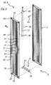
- the in FIG. 1a shown first panel heater 1 according to the invention comprises a front heating plate 2 and a rear heating plate 3, with a connection set 4 on the bottom 5 for connecting the panel radiator 1 to a bottom-side connection not shown with Schuffenvor- and return.
- a venting element 10 is inserted into a functional connection 9.
- a tubular valve carrier 13 with a valve connection 14 for a control valve 15 is connected via an inlet pipe 11 and a drain pipe 12.
- the second Schuffenschrohr 8 is closed by not shown inserts for the flow of a heating medium from the front heating plate 2 in the rear heating plate 3.
- the venting element 10 also closes the first heating medium pipe 7 for the flow of the heating medium.
- a non-illustrated passage in the first Schuffenrohr 7 is opened with the venting element 10, which also allows an overflow of the heating means between the front heating plate 2 and the rear heating plate 3.
- connection fitting 4 consists essentially of two identical connection parts 16, 17.
- Each of the connection parts 16, 17 has a T-shaped first connection element 18 with a first bottom connection stub 19 and two welding stubs 20 and a second connection element 21 with only one other bottom connection piece 22.
- the two connection elements 18, 21 are fluidly connected to a connecting pipe 23.
- the connecting parts 16, 17 are each welded to both the front heating plate 2 and the rear heating plate 3 and connected by means of two welded tabs 24 to give the connection set 4 and thus also the first panel radiator 1 additional stability.
- the left fitting 16 is open to the front heating plate 2 and closed to the rear heating plate 3 and, conversely, the right fitting 17 is closed to the front heating plate 2 and open to the rear heating plate 3.
- the left-hand connection part 16 is thus configured as a flow connection 25 and the right-hand connection part 17 as a return connection 26.
- the bottom connection pieces 19, 22 of the connection set 4 are sealed fluid-tight with blanking plugs, not shown.
- the blind plugs are left on the first floor connection pipe 19, removed from the other floor connection pipe 22 and the latter connected with Schuffenvor- and return.
- the first ground connection 19 are connected accordingly.
- the heating medium flows from the Schuffenvorlauf through the flow connection 25 in the front heating plate 2 and by a guide element 27, as shown in DE 10 2009 003 182 A1 is disclosed in the lower collecting channel 28 in a first riser channel 29, distributed in the upper collecting channel 30, flows through the sink channels 31 in the lower collecting channel 28 and from this through the peripheral riser channel 32 right in the front heating plate 2 back in the upper collecting channel 30th
- the peripheral riser channel 32 is separated from the sinking channels 31 by a separating element 33, which is a fluid-tightly equipped guide element according to the applicant's earlier application.
- the guide element 27 and the separating element 33 (and further identical elements) at the same time serve as spacers between the half shells of the front heating plate 2, which are not shown individually, during welding connection to flow connection 25, return connection 26 and heating medium tubes 7, 8.
- the heating medium flows into a front portion of the first Schuffenbachrohr 7, where it is diverted through the inlet pipe 11, the valve carrier 13 and the drain pipe 12, passes back into the rear portion of the Schuffenrohrs 7 and flows from there into the rear heating plate third From the rear heating plate 3, the heating medium flows through the return connection 26 back into the bottom-side heating medium return.
- the in FIG. 2 shown second plate heater according to the invention 34 corresponds in structure and flow concept essentially the first panel radiator 1, but divergent but in the second Schuffenrohr 35, the venting element 36 and the inlet tube 37 and drain pipe 38 connected valve carrier 39.
- the separating element 40 accordingly separates in the front heating plate 41 on the left the peripheral riser channel 42, through which the heating medium flows into the second heating medium tube 35. Accordingly, the first Schuffenrohr 43 is closed at the second plate radiator 34.
- the in FIG. 3 The third panel radiator 44 according to the invention again corresponds in construction and flow concept substantially the first panel radiator 1.
- the third panel radiator 44 has deviating but only a single Walkerstoffstoffrohr 45 (corresponding to the first Schuffenrohr 7 of the first panel radiator 1), which also only with the front heating plate 46, but not connected to the rear heating plate 47.
- the heating medium flows into the valve carrier 49, which is welded directly to the rear heating plate 47.
- a passage opening 50 is formed, through which the heating means flows from the valve carrier 49 directly into the rear heating plate 47.
- FIG. 4a The fourth panel heater 51 according to the invention shown in construction and flow concept essentially corresponds to the third panel heater 44, but deviatingly has an integrated connection part 52 for a center connection, as shown in FIG DE 10 2009 003 198 A1 the applicant is disclosed.
- connecting part 52 has two bottom connecting pieces 53, one of them as a flow connection 54 and the other as a return connection 55.
- an insert part not shown, is inserted, which connects the flow connection 54 with the front welding spout 56 and the return connection 55 with the rear welding spigot 57.
- the front welding nozzle 56 is welded to the front heating plate 58, the rear to the rear heating plate 59 of the fourth panel heater 51.
- a drainage valve 61 is used on a threaded connector 60, which opens a fluidic connection between the two for draining both the front heating plate 58 and the rear heating plate 59 of the fourth plate heater 51.
Landscapes
- Engineering & Computer Science (AREA)
- Physics & Mathematics (AREA)
- Thermal Sciences (AREA)
- Mechanical Engineering (AREA)
- General Engineering & Computer Science (AREA)
- Chemical & Material Sciences (AREA)
- Combustion & Propulsion (AREA)
- Domestic Hot-Water Supply Systems And Details Of Heating Systems (AREA)
- Central Heating Systems (AREA)
Priority Applications (1)
| Application Number | Priority Date | Filing Date | Title |
|---|---|---|---|
| PL12165131T PL2520868T3 (pl) | 2011-05-05 | 2012-04-23 | Grzejnik płytowy |
Applications Claiming Priority (1)
| Application Number | Priority Date | Filing Date | Title |
|---|---|---|---|
| DE102011050135A DE102011050135A1 (de) | 2011-05-05 | 2011-05-05 | Plattenheizkörper |
Publications (3)
| Publication Number | Publication Date |
|---|---|
| EP2520868A2 true EP2520868A2 (fr) | 2012-11-07 |
| EP2520868A3 EP2520868A3 (fr) | 2013-01-16 |
| EP2520868B1 EP2520868B1 (fr) | 2016-02-24 |
Family
ID=46026681
Family Applications (1)
| Application Number | Title | Priority Date | Filing Date |
|---|---|---|---|
| EP12165131.9A Active EP2520868B1 (fr) | 2011-05-05 | 2012-04-23 | Radiateur à plaques |
Country Status (3)
| Country | Link |
|---|---|
| EP (1) | EP2520868B1 (fr) |
| DE (1) | DE102011050135A1 (fr) |
| PL (1) | PL2520868T3 (fr) |
Families Citing this family (2)
| Publication number | Priority date | Publication date | Assignee | Title |
|---|---|---|---|---|
| DE102015208479A1 (de) * | 2015-03-02 | 2016-09-08 | Hans-Alfred Balg | Heizkörpervorrichtung mit Kreuzdurchströmung |
| EP4473253A4 (fr) * | 2022-02-07 | 2025-12-17 | Commital Isi Ekipmanlari Kalip Sanayi Ve Tic Ltd Sti | Groupe de connecteurs de tuyau comprenant des raccords fabriqués à partir de fil machine pour des radiateurs à panneaux avec 8 entrées-sorties |
Citations (3)
| Publication number | Priority date | Publication date | Assignee | Title |
|---|---|---|---|---|
| DE20014519U1 (de) | 2000-08-21 | 2001-02-08 | Kermi Gmbh, 94447 Plattling | Heizkörper mit mittigem Anschluß |
| DE102009003198A1 (de) | 2009-05-18 | 2010-11-25 | Caradon Heating Europe B.V. | Verfahren zur Herstellung eines Anschlussteils eines Heizkörpers sowie Anschlussteil eines Heizkörpers |
| DE102009003182A1 (de) | 2009-05-18 | 2010-11-25 | Caradon Heating Europe B.V. | Verfahren zur Herstellung einer Heizplatte, Plattenheizkörper und Abstandhalter |
Family Cites Families (4)
| Publication number | Priority date | Publication date | Assignee | Title |
|---|---|---|---|---|
| DE19950985A1 (de) * | 1999-01-12 | 2000-07-27 | Michael Lopic | Temperatur- und/oder zeitgesteuerter Radiator |
| AT411493B (de) * | 1999-10-15 | 2004-01-26 | Vogel & Noot Waermetechnik Ag | Paneelheizkörper sowie stützteil hiefür |
| DE10135215C1 (de) * | 2001-07-24 | 2002-07-25 | Berg Hans Gmbh & Co Kg | Plattenheizkörper |
| DE102010010541A1 (de) * | 2009-03-11 | 2011-03-03 | Hans Berg Gmbh & Co. Kg | Heizkörper und Stell- oder Ventileinrichtung zur Verwendung an einem Heizkörper |
-
2011
- 2011-05-05 DE DE102011050135A patent/DE102011050135A1/de not_active Withdrawn
-
2012
- 2012-04-23 EP EP12165131.9A patent/EP2520868B1/fr active Active
- 2012-04-23 PL PL12165131T patent/PL2520868T3/pl unknown
Patent Citations (3)
| Publication number | Priority date | Publication date | Assignee | Title |
|---|---|---|---|---|
| DE20014519U1 (de) | 2000-08-21 | 2001-02-08 | Kermi Gmbh, 94447 Plattling | Heizkörper mit mittigem Anschluß |
| DE102009003198A1 (de) | 2009-05-18 | 2010-11-25 | Caradon Heating Europe B.V. | Verfahren zur Herstellung eines Anschlussteils eines Heizkörpers sowie Anschlussteil eines Heizkörpers |
| DE102009003182A1 (de) | 2009-05-18 | 2010-11-25 | Caradon Heating Europe B.V. | Verfahren zur Herstellung einer Heizplatte, Plattenheizkörper und Abstandhalter |
Also Published As
| Publication number | Publication date |
|---|---|
| PL2520868T3 (pl) | 2016-08-31 |
| EP2520868A3 (fr) | 2013-01-16 |
| EP2520868B1 (fr) | 2016-02-24 |
| DE102011050135A1 (de) | 2012-11-08 |
Similar Documents
| Publication | Publication Date | Title |
|---|---|---|
| EP3401606B1 (fr) | Agencement de conduite d'air pour un dispositif de hotte aspirante à tirage descendant, socle de meuble et dispositif de hotte aspirante à tirage descendant correspondant | |
| EP2428748B1 (fr) | Radiateur à panneaux et procédé de conduite d'un produit de chauffage | |
| DE202009001056U1 (de) | Heizkreisverteiler | |
| EP2520868B1 (fr) | Radiateur à plaques | |
| DE202007005330U1 (de) | Heizkörper, insbesondere Röhrenheizkörper | |
| EP3228943B1 (fr) | Unité de raccordement d'un dispositif de maintien de pression et/ou de dégazage à un collecteur d'une installation de chauffage | |
| DE3313352C2 (fr) | ||
| DE102005019578A1 (de) | Vorrichtung zum Heizen durch Fluidzirkulation | |
| EP2479510A2 (fr) | Garniture de soupape et corps de chauffage doté de celle-ci | |
| DE202008011672U1 (de) | Rohrverteiler für eine Heizungs- oder Kühlanlage | |
| DE19750109C2 (de) | Anschlußgarnitur und Heizkörper | |
| DE29618611U1 (de) | Heizkörper, insbesondere Rohrheizkörper, Zu- und Ablaufrohr für denselben | |
| EP0595945B1 (fr) | Section de chauffage a double paroi | |
| AT516831B1 (de) | Heizkörper | |
| DE102010053568B4 (de) | Ölluftkühler | |
| DE2619770A1 (de) | Heizkoerper, insbesondere plattenheizkoerper | |
| DE102014004910A1 (de) | Durchflussregelventil | |
| DE202011101271U1 (de) | Duscheinrichtung für WCs oder Bidets | |
| EP1241415B1 (fr) | Radiateur avec assemblage de valve centrale | |
| EP2341291A2 (fr) | Tôle de fixation pour la fixation d'une vanne de gaz sur une conduite de gaz | |
| EP1371916B1 (fr) | Elément de raccordement pour radiateur | |
| AT521052B1 (de) | Heizkörper | |
| EP2527546A1 (fr) | Dispositif de douche pour WC ou bidet | |
| DE202004009356U1 (de) | Hydraulische Weiche für eine Heizungsanlage | |
| DE10004903B4 (de) | Plattenheizkörper |
Legal Events
| Date | Code | Title | Description |
|---|---|---|---|
| PUAI | Public reference made under article 153(3) epc to a published international application that has entered the european phase |
Free format text: ORIGINAL CODE: 0009012 |
|
| AK | Designated contracting states |
Kind code of ref document: A2 Designated state(s): AL AT BE BG CH CY CZ DE DK EE ES FI FR GB GR HR HU IE IS IT LI LT LU LV MC MK MT NL NO PL PT RO RS SE SI SK SM TR |
|
| AX | Request for extension of the european patent |
Extension state: BA ME |
|
| PUAL | Search report despatched |
Free format text: ORIGINAL CODE: 0009013 |
|
| AK | Designated contracting states |
Kind code of ref document: A3 Designated state(s): AL AT BE BG CH CY CZ DE DK EE ES FI FR GB GR HR HU IE IS IT LI LT LU LV MC MK MT NL NO PL PT RO RS SE SI SK SM TR |
|
| AX | Request for extension of the european patent |
Extension state: BA ME |
|
| RIC1 | Information provided on ipc code assigned before grant |
Ipc: F24D 19/00 20060101AFI20121212BHEP |
|
| 17P | Request for examination filed |
Effective date: 20130425 |
|
| 17Q | First examination report despatched |
Effective date: 20141028 |
|
| REG | Reference to a national code |
Ref country code: DE Ref legal event code: R079 Ref document number: 502012006024 Country of ref document: DE Free format text: PREVIOUS MAIN CLASS: F24D0019000000 Ipc: F28D0001030000 |
|
| RIC1 | Information provided on ipc code assigned before grant |
Ipc: F28D 1/03 20060101AFI20150710BHEP Ipc: F28D 21/00 20060101ALI20150710BHEP Ipc: F24D 19/00 20060101ALI20150710BHEP |
|
| GRAP | Despatch of communication of intention to grant a patent |
Free format text: ORIGINAL CODE: EPIDOSNIGR1 |
|
| INTG | Intention to grant announced |
Effective date: 20151027 |
|
| GRAS | Grant fee paid |
Free format text: ORIGINAL CODE: EPIDOSNIGR3 |
|
| GRAA | (expected) grant |
Free format text: ORIGINAL CODE: 0009210 |
|
| AK | Designated contracting states |
Kind code of ref document: B1 Designated state(s): AL AT BE BG CH CY CZ DE DK EE ES FI FR GB GR HR HU IE IS IT LI LT LU LV MC MK MT NL NO PL PT RO RS SE SI SK SM TR |
|
| REG | Reference to a national code |
Ref country code: GB Ref legal event code: FG4D Free format text: NOT ENGLISH |
|
| REG | Reference to a national code |
Ref country code: CH Ref legal event code: EP |
|
| REG | Reference to a national code |
Ref country code: AT Ref legal event code: REF Ref document number: 776942 Country of ref document: AT Kind code of ref document: T Effective date: 20160315 |
|
| REG | Reference to a national code |
Ref country code: IE Ref legal event code: FG4D Free format text: LANGUAGE OF EP DOCUMENT: GERMAN |
|
| REG | Reference to a national code |
Ref country code: DE Ref legal event code: R096 Ref document number: 502012006024 Country of ref document: DE |
|
| REG | Reference to a national code |
Ref country code: FR Ref legal event code: PLFP Year of fee payment: 5 |
|
| REG | Reference to a national code |
Ref country code: NL Ref legal event code: FP |
|
| REG | Reference to a national code |
Ref country code: LT Ref legal event code: MG4D |
|
| PG25 | Lapsed in a contracting state [announced via postgrant information from national office to epo] |
Ref country code: FI Free format text: LAPSE BECAUSE OF FAILURE TO SUBMIT A TRANSLATION OF THE DESCRIPTION OR TO PAY THE FEE WITHIN THE PRESCRIBED TIME-LIMIT Effective date: 20160224 Ref country code: NO Free format text: LAPSE BECAUSE OF FAILURE TO SUBMIT A TRANSLATION OF THE DESCRIPTION OR TO PAY THE FEE WITHIN THE PRESCRIBED TIME-LIMIT Effective date: 20160524 Ref country code: HR Free format text: LAPSE BECAUSE OF FAILURE TO SUBMIT A TRANSLATION OF THE DESCRIPTION OR TO PAY THE FEE WITHIN THE PRESCRIBED TIME-LIMIT Effective date: 20160224 Ref country code: GR Free format text: LAPSE BECAUSE OF FAILURE TO SUBMIT A TRANSLATION OF THE DESCRIPTION OR TO PAY THE FEE WITHIN THE PRESCRIBED TIME-LIMIT Effective date: 20160525 Ref country code: IT Free format text: LAPSE BECAUSE OF FAILURE TO SUBMIT A TRANSLATION OF THE DESCRIPTION OR TO PAY THE FEE WITHIN THE PRESCRIBED TIME-LIMIT Effective date: 20160224 Ref country code: ES Free format text: LAPSE BECAUSE OF FAILURE TO SUBMIT A TRANSLATION OF THE DESCRIPTION OR TO PAY THE FEE WITHIN THE PRESCRIBED TIME-LIMIT Effective date: 20160224 |
|
| PG25 | Lapsed in a contracting state [announced via postgrant information from national office to epo] |
Ref country code: LV Free format text: LAPSE BECAUSE OF FAILURE TO SUBMIT A TRANSLATION OF THE DESCRIPTION OR TO PAY THE FEE WITHIN THE PRESCRIBED TIME-LIMIT Effective date: 20160224 Ref country code: SE Free format text: LAPSE BECAUSE OF FAILURE TO SUBMIT A TRANSLATION OF THE DESCRIPTION OR TO PAY THE FEE WITHIN THE PRESCRIBED TIME-LIMIT Effective date: 20160224 Ref country code: RS Free format text: LAPSE BECAUSE OF FAILURE TO SUBMIT A TRANSLATION OF THE DESCRIPTION OR TO PAY THE FEE WITHIN THE PRESCRIBED TIME-LIMIT Effective date: 20160224 Ref country code: PT Free format text: LAPSE BECAUSE OF FAILURE TO SUBMIT A TRANSLATION OF THE DESCRIPTION OR TO PAY THE FEE WITHIN THE PRESCRIBED TIME-LIMIT Effective date: 20160624 Ref country code: LT Free format text: LAPSE BECAUSE OF FAILURE TO SUBMIT A TRANSLATION OF THE DESCRIPTION OR TO PAY THE FEE WITHIN THE PRESCRIBED TIME-LIMIT Effective date: 20160224 |
|
| PG25 | Lapsed in a contracting state [announced via postgrant information from national office to epo] |
Ref country code: DK Free format text: LAPSE BECAUSE OF FAILURE TO SUBMIT A TRANSLATION OF THE DESCRIPTION OR TO PAY THE FEE WITHIN THE PRESCRIBED TIME-LIMIT Effective date: 20160224 Ref country code: EE Free format text: LAPSE BECAUSE OF FAILURE TO SUBMIT A TRANSLATION OF THE DESCRIPTION OR TO PAY THE FEE WITHIN THE PRESCRIBED TIME-LIMIT Effective date: 20160224 |
|
| REG | Reference to a national code |
Ref country code: DE Ref legal event code: R097 Ref document number: 502012006024 Country of ref document: DE |
|
| PG25 | Lapsed in a contracting state [announced via postgrant information from national office to epo] |
Ref country code: SM Free format text: LAPSE BECAUSE OF FAILURE TO SUBMIT A TRANSLATION OF THE DESCRIPTION OR TO PAY THE FEE WITHIN THE PRESCRIBED TIME-LIMIT Effective date: 20160224 Ref country code: SK Free format text: LAPSE BECAUSE OF FAILURE TO SUBMIT A TRANSLATION OF THE DESCRIPTION OR TO PAY THE FEE WITHIN THE PRESCRIBED TIME-LIMIT Effective date: 20160224 Ref country code: CZ Free format text: LAPSE BECAUSE OF FAILURE TO SUBMIT A TRANSLATION OF THE DESCRIPTION OR TO PAY THE FEE WITHIN THE PRESCRIBED TIME-LIMIT Effective date: 20160224 Ref country code: RO Free format text: LAPSE BECAUSE OF FAILURE TO SUBMIT A TRANSLATION OF THE DESCRIPTION OR TO PAY THE FEE WITHIN THE PRESCRIBED TIME-LIMIT Effective date: 20160224 |
|
| REG | Reference to a national code |
Ref country code: CH Ref legal event code: PL |
|
| PG25 | Lapsed in a contracting state [announced via postgrant information from national office to epo] |
Ref country code: LU Free format text: LAPSE BECAUSE OF FAILURE TO SUBMIT A TRANSLATION OF THE DESCRIPTION OR TO PAY THE FEE WITHIN THE PRESCRIBED TIME-LIMIT Effective date: 20160423 |
|
| PLBE | No opposition filed within time limit |
Free format text: ORIGINAL CODE: 0009261 |
|
| STAA | Information on the status of an ep patent application or granted ep patent |
Free format text: STATUS: NO OPPOSITION FILED WITHIN TIME LIMIT |
|
| REG | Reference to a national code |
Ref country code: IE Ref legal event code: MM4A |
|
| PG25 | Lapsed in a contracting state [announced via postgrant information from national office to epo] |
Ref country code: LI Free format text: LAPSE BECAUSE OF NON-PAYMENT OF DUE FEES Effective date: 20160430 Ref country code: CH Free format text: LAPSE BECAUSE OF NON-PAYMENT OF DUE FEES Effective date: 20160430 |
|
| 26N | No opposition filed |
Effective date: 20161125 |
|
| PG25 | Lapsed in a contracting state [announced via postgrant information from national office to epo] |
Ref country code: BG Free format text: LAPSE BECAUSE OF FAILURE TO SUBMIT A TRANSLATION OF THE DESCRIPTION OR TO PAY THE FEE WITHIN THE PRESCRIBED TIME-LIMIT Effective date: 20160524 Ref country code: SI Free format text: LAPSE BECAUSE OF FAILURE TO SUBMIT A TRANSLATION OF THE DESCRIPTION OR TO PAY THE FEE WITHIN THE PRESCRIBED TIME-LIMIT Effective date: 20160224 |
|
| REG | Reference to a national code |
Ref country code: FR Ref legal event code: PLFP Year of fee payment: 6 |
|
| PG25 | Lapsed in a contracting state [announced via postgrant information from national office to epo] |
Ref country code: IE Free format text: LAPSE BECAUSE OF NON-PAYMENT OF DUE FEES Effective date: 20160423 |
|
| REG | Reference to a national code |
Ref country code: FR Ref legal event code: PLFP Year of fee payment: 7 |
|
| PG25 | Lapsed in a contracting state [announced via postgrant information from national office to epo] |
Ref country code: HU Free format text: LAPSE BECAUSE OF FAILURE TO SUBMIT A TRANSLATION OF THE DESCRIPTION OR TO PAY THE FEE WITHIN THE PRESCRIBED TIME-LIMIT; INVALID AB INITIO Effective date: 20120423 Ref country code: CY Free format text: LAPSE BECAUSE OF FAILURE TO SUBMIT A TRANSLATION OF THE DESCRIPTION OR TO PAY THE FEE WITHIN THE PRESCRIBED TIME-LIMIT Effective date: 20160224 |
|
| PG25 | Lapsed in a contracting state [announced via postgrant information from national office to epo] |
Ref country code: MK Free format text: LAPSE BECAUSE OF FAILURE TO SUBMIT A TRANSLATION OF THE DESCRIPTION OR TO PAY THE FEE WITHIN THE PRESCRIBED TIME-LIMIT Effective date: 20160224 Ref country code: IS Free format text: LAPSE BECAUSE OF FAILURE TO SUBMIT A TRANSLATION OF THE DESCRIPTION OR TO PAY THE FEE WITHIN THE PRESCRIBED TIME-LIMIT Effective date: 20160224 Ref country code: MC Free format text: LAPSE BECAUSE OF FAILURE TO SUBMIT A TRANSLATION OF THE DESCRIPTION OR TO PAY THE FEE WITHIN THE PRESCRIBED TIME-LIMIT Effective date: 20160224 Ref country code: MT Free format text: LAPSE BECAUSE OF FAILURE TO SUBMIT A TRANSLATION OF THE DESCRIPTION OR TO PAY THE FEE WITHIN THE PRESCRIBED TIME-LIMIT Effective date: 20160224 |
|
| PG25 | Lapsed in a contracting state [announced via postgrant information from national office to epo] |
Ref country code: AL Free format text: LAPSE BECAUSE OF FAILURE TO SUBMIT A TRANSLATION OF THE DESCRIPTION OR TO PAY THE FEE WITHIN THE PRESCRIBED TIME-LIMIT Effective date: 20160224 |
|
| REG | Reference to a national code |
Ref country code: DE Ref legal event code: R082 Ref document number: 502012006024 Country of ref document: DE Representative=s name: BAUER WAGNER PELLENGAHR SROKA PATENT- & RECHTS, DE Ref country code: DE Ref legal event code: R082 Ref document number: 502012006024 Country of ref document: DE Representative=s name: BAUER PSU PARTG MBB, DE |
|
| P01 | Opt-out of the competence of the unified patent court (upc) registered |
Effective date: 20230523 |
|
| PGFP | Annual fee paid to national office [announced via postgrant information from national office to epo] |
Ref country code: NL Payment date: 20250424 Year of fee payment: 14 |
|
| PGFP | Annual fee paid to national office [announced via postgrant information from national office to epo] |
Ref country code: DE Payment date: 20250430 Year of fee payment: 14 |
|
| PGFP | Annual fee paid to national office [announced via postgrant information from national office to epo] |
Ref country code: BE Payment date: 20250424 Year of fee payment: 14 |
|
| PGFP | Annual fee paid to national office [announced via postgrant information from national office to epo] |
Ref country code: FR Payment date: 20250424 Year of fee payment: 14 |
|
| PGFP | Annual fee paid to national office [announced via postgrant information from national office to epo] |
Ref country code: AT Payment date: 20250417 Year of fee payment: 14 |
|
| PGFP | Annual fee paid to national office [announced via postgrant information from national office to epo] |
Ref country code: TR Payment date: 20250407 Year of fee payment: 14 |
|
| PGFP | Annual fee paid to national office [announced via postgrant information from national office to epo] |
Ref country code: GB Payment date: 20260304 Year of fee payment: 15 |
|
| PGFP | Annual fee paid to national office [announced via postgrant information from national office to epo] |
Ref country code: PL Payment date: 20260330 Year of fee payment: 15 |