EP2522486B1 - Werkzeugwechseleinrichtung - Google Patents
Werkzeugwechseleinrichtung Download PDFInfo
- Publication number
- EP2522486B1 EP2522486B1 EP11003824.7A EP11003824A EP2522486B1 EP 2522486 B1 EP2522486 B1 EP 2522486B1 EP 11003824 A EP11003824 A EP 11003824A EP 2522486 B1 EP2522486 B1 EP 2522486B1
- Authority
- EP
- European Patent Office
- Prior art keywords
- tool
- chain guide
- insert
- work station
- tool insert
- Prior art date
- Legal status (The legal status is an assumption and is not a legal conclusion. Google has not performed a legal analysis and makes no representation as to the accuracy of the status listed.)
- Active
Links
Images


Classifications
-
- B—PERFORMING OPERATIONS; TRANSPORTING
- B29—WORKING OF PLASTICS; WORKING OF SUBSTANCES IN A PLASTIC STATE IN GENERAL
- B29C—SHAPING OR JOINING OF PLASTICS; SHAPING OF MATERIAL IN A PLASTIC STATE, NOT OTHERWISE PROVIDED FOR; AFTER-TREATMENT OF THE SHAPED PRODUCTS, e.g. REPAIRING
- B29C51/00—Shaping by thermoforming, i.e. shaping sheets or sheet like preforms after heating, e.g. shaping sheets in matched moulds or by deep-drawing; Apparatus therefor
- B29C51/26—Component parts, details or accessories; Auxiliary operations
-
- B—PERFORMING OPERATIONS; TRANSPORTING
- B29—WORKING OF PLASTICS; WORKING OF SUBSTANCES IN A PLASTIC STATE IN GENERAL
- B29C—SHAPING OR JOINING OF PLASTICS; SHAPING OF MATERIAL IN A PLASTIC STATE, NOT OTHERWISE PROVIDED FOR; AFTER-TREATMENT OF THE SHAPED PRODUCTS, e.g. REPAIRING
- B29C31/00—Handling, e.g. feeding of the material to be shaped, storage of plastics material before moulding; Automation, i.e. automated handling lines in plastics processing plants, e.g. using manipulators or robots
- B29C31/006—Handling moulds, e.g. between a mould store and a moulding machine
-
- B—PERFORMING OPERATIONS; TRANSPORTING
- B29—WORKING OF PLASTICS; WORKING OF SUBSTANCES IN A PLASTIC STATE IN GENERAL
- B29C—SHAPING OR JOINING OF PLASTICS; SHAPING OF MATERIAL IN A PLASTIC STATE, NOT OTHERWISE PROVIDED FOR; AFTER-TREATMENT OF THE SHAPED PRODUCTS, e.g. REPAIRING
- B29C51/00—Shaping by thermoforming, i.e. shaping sheets or sheet like preforms after heating, e.g. shaping sheets in matched moulds or by deep-drawing; Apparatus therefor
- B29C51/26—Component parts, details or accessories; Auxiliary operations
- B29C51/42—Heating or cooling
- B29C51/428—Heating or cooling of moulds or mould parts
-
- B—PERFORMING OPERATIONS; TRANSPORTING
- B65—CONVEYING; PACKING; STORING; HANDLING THIN OR FILAMENTARY MATERIAL
- B65B—MACHINES, APPARATUS OR DEVICES FOR, OR METHODS OF, PACKAGING ARTICLES OR MATERIALS; UNPACKING
- B65B47/00—Apparatus or devices for forming pockets or receptacles in or from sheets, blanks, or webs, comprising essentially a die into which the material is pressed or a folding die through which the material is moved
-
- B—PERFORMING OPERATIONS; TRANSPORTING
- B65—CONVEYING; PACKING; STORING; HANDLING THIN OR FILAMENTARY MATERIAL
- B65B—MACHINES, APPARATUS OR DEVICES FOR, OR METHODS OF, PACKAGING ARTICLES OR MATERIALS; UNPACKING
- B65B59/00—Arrangements to enable machines to handle articles of different sizes, to produce packages of different sizes, to vary the contents of packages, to handle different types of packaging material, or to give access for cleaning or maintenance purposes
- B65B59/04—Machines constructed with readily-detachable units or assemblies, e.g. to facilitate maintenance
-
- Y—GENERAL TAGGING OF NEW TECHNOLOGICAL DEVELOPMENTS; GENERAL TAGGING OF CROSS-SECTIONAL TECHNOLOGIES SPANNING OVER SEVERAL SECTIONS OF THE IPC; TECHNICAL SUBJECTS COVERED BY FORMER USPC CROSS-REFERENCE ART COLLECTIONS [XRACs] AND DIGESTS
- Y10—TECHNICAL SUBJECTS COVERED BY FORMER USPC
- Y10T—TECHNICAL SUBJECTS COVERED BY FORMER US CLASSIFICATION
- Y10T483/00—Tool changing
- Y10T483/10—Process
-
- Y—GENERAL TAGGING OF NEW TECHNOLOGICAL DEVELOPMENTS; GENERAL TAGGING OF CROSS-SECTIONAL TECHNOLOGIES SPANNING OVER SEVERAL SECTIONS OF THE IPC; TECHNICAL SUBJECTS COVERED BY FORMER USPC CROSS-REFERENCE ART COLLECTIONS [XRACs] AND DIGESTS
- Y10—TECHNICAL SUBJECTS COVERED BY FORMER USPC
- Y10T—TECHNICAL SUBJECTS COVERED BY FORMER US CLASSIFICATION
- Y10T483/00—Tool changing
- Y10T483/16—Tool changing with means to transfer work
Definitions
- the invention relates to a tool changing device of a thermoforming packaging machine according to the preamble of claim 1 and a method according to claim 8 for changing a tool insertion.
- thermoforming packaging machine is known in which a mold lower part is pulled out of the thermoforming packaging machine laterally. This takes place without influencing the film web.
- Tool shells are usually lifted up and replaced in thermoforming packaging machines for replacement.
- To be changed tool inserts in tool shells, such as forming or sealing stations, which are located with a part between the transport chains or the chain guides are raised upwards as a unit with the upper tool or pulled out in the direction of production above the film web from the upper tool and replaced.
- the object of the invention is to provide a possibility for a lateral change of a tool insert of a tool upper part in a thermoforming packaging machine.
- the tool changing device for a tool insert of a workstation of a thermoforming packaging machine, the both sides of a web-like
- Material provides a chain guide for transporting the sheet material through the workstation, characterized by a relative to the tool insert vertically movable chain guide to move the tool insert laterally relative to the production direction can.
- the chain guide is lowered so far down that the chain guide does not represent a disturbing contour against movement of the tool insertion over the chain guide away.
- the chain guide is raised so far up that the movement of the tool insert is not hindered by the chain guide here.
- the chain guide is movable relative to the tool insert in a change position and in a working position, wherein the change position represents a relation to the transported along the thermoforming packaging film web or lowered position.
- the chain guide is in the working position for transporting the film web, wherein the film web is in the area of the forming station at the same height as in the areas of the insertion path, the sealing station and the cutting stations along the production direction.
- a separately driven by a tool lower part or upper tool part of the workstation chain guide it is preferably by means of at least one actuator, such as a pneumatic cylinder or a servomotor, movable to be independent of other, partly also parallel running movements of a work station to be movable.
- actuator such as a pneumatic cylinder or a servomotor
- the tool insert is a heating plate when the workstation is a forming station, or the tool insert is a sealing plate when the workstation a sealing station is.
- a tool insert receiving the tool carrier can be fixedly mounted on the machine frame and the example format-dependent tool insert for replacement or cleaning purposes easily and ergonomically adapted to be removed from the thermoforming packaging machine side.
- the tool insert is in contact with the tool carrier or a cooling plate of the forming station during operation of the forming station to permanently cool a tool insert designed as a heating plate.
- the cooling circuit is provided in fixedly mounted on the machine frame tool carrier of the forming station and omission of the cooling water before pulling out of the tool insert can be omitted, resulting in a shortening of the change time.
- thermoforming packaging machine is equipped with a tool changing device according to the invention to facilitate the change of a tool insertion and shorten the time required for it.
- the inventive method for operating a tool changing device of a workstation in a thermoforming packaging machine provides a chain guide for transporting a web-like material through the workstation and the chain guide is moved vertically at least in the workstation relative to a tool drawer in a change position to the tool insert relative to the production direction laterally to move to the switch. This allows a simple and quick change of the tool insertion laterally out of the thermoforming packaging machine, without the film web must be removed in the workstation and without the need for mechanical modifications must be made.
- the movement of the chain guide takes place in the change position with or after the opening of the respective workstation, wherein when opening the workstation, a tool which is located on the side facing away from the product of the sheet material, relative to the tool insert, which is facing on a product Side of the sheet material is moved away.
- the movement of the chain guide takes place in the working position before or with the closing of the respective workstation, wherein when closing the workstation, a tool located on the side facing away from the product of the sheet material is moved relative to the tool insert, which is located on the product side facing the sheet material is moved.
- the chain guide is moved by a tool upper part or a lower tool part of the respective workstation. Thus, no further drive for this movement is needed.
- the movement of the chain guide by means of an actuator, preferably a pneumatic cylinder or a servomotor, executed.
- the movement of the chain guide is preferably carried out while the sheet material is stationary, to avoid a special stress on the chain guide and the sheet material.
- the workstation is a forming station or a sealing station, these having tool inserts such as heating plate or sealing plate.
- the tool insert is cooled indirectly by means of a cooling plate of the forming station by the tool insert and the cooling plate of the forming station are brought into surface contact and the active cooling means of a coolant circuit is present only in the non-movable cooling plate. Neither a separation of the tool insert from the cooling water inlet and cooling water drain nor a discharge of the water from the inside of the tool insert are necessary. This leads to a further simplification of the tool change.
- the tool drawer is automatically unlocked by means of a control for removal from the workstation and / or automatically locked after insertion into the workstation.
- a control for removal from the workstation and / or automatically locked after insertion into the workstation.
- the exact and repeatable position of the tool insert becomes secured in the workstation and in conjunction with an optional sensors, a machine start can be enabled or disabled accordingly.
- FIG. 1 shows an embodiment of a thermoforming packaging machine 1 in a perspective view.
- the thermoforming packaging machine 1 has (at least) three workstations, namely a forming station 2, an evacuation and sealing station 3 and a separation station 4. All of these workstations 2, 3, 4 act on a web-shaped material 5, which is a plastic film web is. At a standstill of the web-shaped material 5 during the intermittent operation of the thermoforming packaging machine 1, the mold 6 is moved perpendicular to the plane of the web-shaped material 5 to deep draw in the web-shaped material 5 packaging trays.
- the sealing station 3 has a sealing tool upper part 7 and a sealing tool lower part 8. Due to the movement of the sealing tool upper part 7 and / or the sealing tool lower part 8 towards each other, a closed position can be created between the two tool parts 7, 8 Sealing chamber are formed in which the previously filled with a product packaging tray in the web-shaped material 5 sealed with a cover film, not shown, and thus can be closed. It is conceivable to evacuate the sealing chamber between the two tool parts 7, 8 and thus the packaging tray before sealing and / or to treat it with a replacement gas. After sealing, the sealing tool top 7 and the sealing tool bottom 8 are again removed from each other to expose the packaging tray and allow further transport of the sheet material 5.
- the separating station 4 is a cross-cutting device in which a separating knife 9 is provided as a tool part.
- This separating knife 9 can be moved in the vertical direction, i. perpendicular to the plane of the web-shaped material 5, are moved to sever the web-shaped material 5.
- the thermoforming packaging machine 1 defines a production direction R in which the sheet-like material 5 is transported through at least some of the work stations, in the present embodiment by the sealing station 3 and the separation station 4.
- the packaging material 5 is transported against this production direction R before it is deflected about a virtual, horizontal axis 10 and brought in this way from a first transport plane 11 in a second transport plane 12.
- the thermoforming packaging machine 1 has a frame 13 which is arranged horizontally between the two transport planes 11, 12.
- the frame 13 comprises a plurality of lateral longitudinal struts 14, which are aligned in the production direction R of the packaging machine 1, and a plurality of transverse struts 15, which connect the longitudinal struts 14 with each other.
- the frame 13 has two longitudinal struts 14 oriented parallel to one another and located at the same height. These longitudinal struts 14 extend at least over the length of a workstation 2, 3, 4 in the production direction R.
- the shaft 16 is connected to a drive, for example, an electric motor, preferably a servo motor. In the present embodiment, the shaft 16 can be driven by the drive alternately in different directions of rotation.
- FIG. 1 shows the thermoforming packaging machine in a state in which the tools 6, 7, 8, 9 of the respective workstations 2, 3, 4 are opened to allow further transport of the sheet material 5.
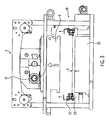
- FIG. 2 shows the forming station 2 in the production direction R with a tool changing device 19 according to the invention, comprising the mold 6 and a below the web-shaped material 5 arranged tool drawer 20 which is guided or held on the tool carrier 21.
- a chain guide 22 leads on both sides each a staple or transport chain 23, which transports the web-like material along the production direction R by the workstations intermittently.
- the forming station is in this FIG. 2 shown in a closed position, wherein the shaft 16 is in a lower position.
- FIG. 3 the forming station 2 is shown in an open position, in which over the rotation of the shaft 16, the mold 6 is raised.
- the chain guide 22 with the transport chain 23 and the held web-shaped material 5 is raised by a distance s.
- This movement can be carried out via a mechanism, not shown, in connection with the mold 6 or be realized by a separate drive, such as a pneumatic cylinder or a servomotor.
- the distance s corresponds to the length that is necessary for the side of the chain guide 22 facing the tool insert 20 to be located above the upper region of the tool insert 20.
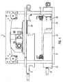
- FIG. 4 is like in FIG. 3 the forming station 2 shown in the open position.
- the tool insert 20 and the mold 6 are partially pulled out laterally to the left from the forming station 2 or from the thermoforming packaging machine 1.
- Guides 24 guide the tool insert 20 and the forming tool 6 during the lateral movement and as long as part of the tools 20, 6 are still in the forming station 2 or in the guides 24.
- the tool insert 20 moves at a small distance below the left chain guide 22 laterally outward.
- the tool holder 21 is designed as a cooling plate with a water cycle, not shown, and is located in the plane 25 in a planar contact with the tool insert 20.
- fixing elements 26 are attached to the stop side right at or above the tool carrier.
- a clamping device 27 of the tool drawer 20 is secured or fastened on the tool carrier 21 in a working position.
Landscapes
- Engineering & Computer Science (AREA)
- Mechanical Engineering (AREA)
- Robotics (AREA)
- Containers And Plastic Fillers For Packaging (AREA)
- Auxiliary Devices For And Details Of Packaging Control (AREA)
Description
- Die Erfindung bezieht sich auf eine Werkzeugwechseleinrichtung einer Tiefziehverpackungsmaschine gemäß dem Oberbegriff des Anspruchs 1 und ein Verfahren nach Anspruch 8 zum Wechseln eines Werkzeugeinschubs.
- Aus der
EP 1 234 765 B1 ist ein Werkzeugwechselsystem bekannt, bei dem Werkzeugteile in Produktionsrichtung automatisch über eine Übergabeablage in eine Parkposition gewechselt werden, ohne dass dabei die Folienbahn in diesem Bereich entfernt werden muss. Dabei bleiben alle Werkzeug in oder an der Maschine. Es ist ein hoher Platzbedarf für die in der Parkposition befindlichen Werkzeuge und für die Übergabeablage vorzusehen. Der Platzbedarf beschränkt auch die Anzahl der möglichen Werkzeuge in der Parkposition. - Aus der
EP 0 467 069 A1 ist eine Tiefziehverpackungsmaschine bekannt, bei der ein Formwerkzeugunterteil seitlich aus der Tiefziehverpackungsmaschine herausziehbar ist. Dies findet ohne Beeinflussung der Folienbahn statt. - Werkzeugoberteile werden bei Tiefziehverpackungsmaschinen zu einem Austausch üblicherweise nach oben angehoben und gewechselt. Zu wechselnde Werkzeugeinschübe in Werkzeugoberteilen, beispielsweise an Form- oder Siegelstationen, die sich mit einem Teil zwischen den Transportketten bzw. den Kettenführungen befinden, werden nach oben als Einheit mit dem Werkzeugoberteil angehoben oder in Produktionsrichtung oberhalb der Folienbahn aus den Werkzeugoberteilen herausgezogen und gewechselt.
- Die Aufgabe der Erfindung ist es, eine Möglichkeit für einen seitlichen Wechsel von einem Werkzeugeinschub eines Werkzeugoberteils in einer Tiefziehverpackungsmaschine zur Verfügung zu stellen.
- Diese Aufgabe wird gelöst durch eine Werkzeugwechseleinrichtung mit den Merkmalen des Anspruchs 1 bzw. ein Verfahren nach Anspruch 8. Vorteilhafte Weiterbildungen der Erfindung sind in den Unteransprüchen angegeben.
- Die erfindungsgemäße Werkzeugwechseleinrichtung für einen Werkzeugeinschub einer Arbeitsstation einer Tiefziehverpackungsmaschine, die beidseitig eines bahnförmigen
- Materials eine Kettenführung zum Transportieren des bahnförmigen Materials durch die Arbeitsstation vorsieht, zeichnet sich durch eine relativ zum Werkzeugeinschub vertikal bewegbare Kettenführung aus, um den Werkzeugeinschub seitlich gegenüber der Produktionsrichtung verschieben zu können. Für Werkzeugeinschübe, die oberhalb der Folienbahn vorgesehen sind, wird die Kettenführung soweit nach unten abgesenkt, dass die Kettenführung keine Störkontur gegenüber einer Bewegung des Werkzeugeinschubs über die Kettenführung hinweg darstellt. Bei Werkzeugeinschüben, die sich unterhalb der Folienbahn befinden, wird die Kettenführung soweit nach oben angehoben, dass auch hier die Bewegung des Werkzeugeinschubs nicht durch die Kettenführung behindert wird. Zur Ausführung der Wechselfunktion ist es ausreichend, wenn die Bewegbarkeit der Kettenführung in dem Bereich vorgesehen ist, der für den Werkzeugeinschub benötigt wird.
- Vorzugsweise ist die Kettenführung relativ zum Werkzeugeinschub in eine Wechselposition und in eine Arbeitsposition bewegbar, wobei die Wechselposition eine gegenüber der entlang der Tiefziehverpackungsmaschine zu transportierenden Folienbahn abgesenkte bzw. angehobene Position darstellt. Die Kettenführung befindet sich in der Arbeitsposition zum Transportieren der Folienbahn, wobei sich die Folienbahn im Bereich der Formstation auf gleicher Höhe wie in den Bereichen der Einlegestrecke, der Siegelstation und der Schneidstationen entlang der Produktionsrichtung befindet.
- Es ist besonders vorteilhaft, wenn die Kettenführung in ihrer Bewegung an ein Werkzeugoberteil oder an ein Werkzeugunterteil gekoppelt ist. Somit sind keine weiteren Antriebssysteme notwendig und es wird eine einfache und kostengünstige Konstruktion ermöglicht.
- Im Fall einer separat von einem Werkzeugunterteil oder Werkzeugoberteil der Arbeitsstation angetriebenen Kettenführung ist diese vorzugsweise mittels wenigstens eines Aktuators, beispielsweise eines Pneumatikzylinders oder eines Servomotors, bewegbar, um unabhängig von anderen, zum Teil auch parallel ablaufenden Bewegungen einer Arbeitsstation bewegbar zu sein. Somit können beim Wechsel von Werkzeugen oberhalb und unterhalb der Folienbahn innerhalb einer Arbeitsstation die Werkzeuge in die jeweils für sich vorteilhafteste Wechselposition gebracht werden.
- Vorzugsweise ist der Werkzeugeinschub eine Heizplatte, wenn die Arbeitsstation eine Formstation ist, oder der Werkzeugeinschub ist eine Siegelplatte, wenn die Arbeitsstation eine Siegelstation ist. Somit kann ein den Werkzeugeinschub aufnehmender Werkzeugträger fest am Maschinenrahmen montiert sein und der beispielsweise formatabhängige Werkzeugeinschub zum Austausch oder zu Reinigungszwecken einfach und ergonomisch angepasst aus der Tiefziehverpackungsmaschine seitlich entnommen werden.
- Vorzugsweise steht der Werkzeugeinschub mit dem Werkzeugträger bzw. einer Kühlplatte der Formstation während des Betriebs der Formstation in Kontakt, um einen als Heizplatte ausgeführten Werkzeugeinschub dauerhaft zu kühlen. Dabei ist der Kühlkreislauf im fest am Maschinenrahmen angebrachten Werkzeugträger der Formstation vorgesehen und ein Auslassen des Kühlwassers vor dem Herausziehen des Werkzeugeinschubs kann entfallen, was zu einer Verkürzung der Wechselzeit führt.
- Vorzugsweise ist eine Tiefziehverpackungsmaschine mit einer erfindungsgemäßen Werkzeugwechseleinrichtung ausgerüstet, um den Wechsel eines Werkzeugeinschubs zu erleichtern und die dafür benötigte Zeit zu verkürzen.
- Das erfindungsgemäße Verfahren zum Betrieb einer Werkzeugwechseleinrichtung einer Arbeitsstation in einer Tiefziehverpackungsmaschine sieht eine Kettenführung zum Transportieren eines bahnförmigen Materials durch die Arbeitsstation vor und die Kettenführung wird wenigstens im Bereich der Arbeitsstation relativ zu einem Werkzeugeinschub in eine Wechselposition vertikal bewegt, um den Werkzeugeinschub gegenüber der Produktionsrichtung seitlich zum Wechseln zu verschieben. Dies ermöglicht einen einfachen und schnellen Wechsel des Werkzeugeinschubs seitlich aus der Tiefziehverpackungsmaschine heraus, ohne dass die Folienbahn im Bereich der Arbeitsstation entfernt werden muss und ohne dass mechanische Umbauten vorgenommen werden müssen.
- Bevorzugt erfolgt die Bewegung der Kettenführung in die Wechselposition mit oder nach dem Öffnen der jeweiligen Arbeitsstation, wobei beim Öffnen der Arbeitsstation ein Werkzeug, das sich an der einem Produkt abgewandten Seite des bahnförmigen Materials befindet, relativ vom Werkzeugeinschub, der sich auf der einem Produkt zugewandten Seite des bahnförmigen Materials befindet, wegbewegt wird.
- Vorzugsweise erfolgt die Bewegung der Kettenführung in die Arbeitsposition vor oder mit dem Schließen der jeweiligen Arbeitsstation, wobei beim Schließen der Arbeitsstation ein Werkzeug, das sich an der einem Produkt abgewandten Seite des bahnförmigen Materials befindet, relativ zum Werkzeugeinschub, der sich auf der einem Produkt zugewandten Seite des bahnförmigen Materials befindet, hinbewegt wird.
- In einer besonders vorteilhaften Ausführung wird die Kettenführung durch ein Werkzeugoberteil oder ein Werkzeugunterteil der jeweiligen Arbeitsstation bewegt. Somit wird kein weiterer Antrieb für diese Bewegung benötigt.
- Alternativ wird die Bewegung der Kettenführung mittels eines Aktuators, vorzugsweise eines Pneumatikzylinders oder eines Servomotors, ausgeführt.
- Die Bewegung der Kettenführung erfolgt bevorzugt, während das bahnförmige Material stillsteht, um eine besondere Beanspruchung an die Kettenführung und an das bahnförmige Material zu vermeiden.
- Vorzugsweise ist die Arbeitsstation eine Formstation oder eine Siegelstation, wobei diese Werkzugeinschübe wie Heizplatte oder Siegelplatte aufweisen.
- Bevorzugt wird der Werkzeugeinschub mittels einer Kühlplatte der Formstation indirekt gekühlt, indem der Werkzeugeinschub und die Kühlplatte der Formstation in flächigen Kontakt gebracht werden und die aktive Kühlung mittels eines Kühlmittelkreislaufs nur in der nicht bewegbaren Kühlplatte vorhanden ist. Weder ein Trennen des Werkzeugeinschubs vom Kühlwasserzulauf und Kühlwasserablauf noch ein Auslassen des Wassers aus dem Inneren des Werkzeugeinschubs sind notwendig. Dies führt zu einer weiteren Vereinfachung des Werkzeugwechsels.
- Zweckmäßig ist es, die Energieleitungen beispielsweise für Strom, Druckluft oder Vakuum mit Steckverbindungen zwischen dem Werkzeugeinschub und dem Werkzeugträger vorzusehen, die automatisch beim Herausziehen des Werkzeugeinschubs gelöst und beim Einschieben des Werkzeugeinschubs verbunden werden. Damit entfallen manuelle Tätigkeiten zum Abklemmen oder Abstecken der einzelnen Leitungsverbindungen und die Wechselzeit wird verkürzt.
- Bevorzugt wird der Werkzeugeinschub automatisch mittels einer Steuerung zum Herausnehmen aus der Arbeitsstation entriegelt und/oder automatisch nach dem Einschieben in die Arbeitsstation verriegelt. Somit wird die exakte und wiederholbare Position des Werkzeugeinschubs in der Arbeitsstation sichergestellt und in Verbindung mit einer optionalen Sensorik kann ein Maschinenstart entsprechend freigegeben oder gesperrt werden.
- Im Folgenden wird ein vorteilhaftes Ausführungsbeispiel der Erfindung anhand einer Zeichnung näher erläutert.
- Im Einzelnen zeigen:
-
Figur 1 eine perspektivische Ansicht einer Tiefziehverpackungsmaschine mit geöffneten Arbeitsstationen, -
Figur 2 eine Schnittansicht durch die Formstation in Produktionsrichtung mit einer erfindungsgemäßen Werkzeugwechseleinrichtung in einer geschlossenen Stellung, -
Figur 3 eine Schnittansicht durch die Formstation in Produktionsrichtung in einer geöffneten Stellung und mit angehobener Kettenführung, -
Figur 4 wieFigur 3 mit seitlich herausbewegtem Werkzeugeinschub. - Gleiche Komponenten sind in den Figuren durchgängig mit gleichen Bezugszeichen versehen.
-
Figur 1 zeigt ein Ausführungsbeispiel einer Tiefziehverpackungsmaschine 1 in einer perspektivischen Ansicht. - Die Tiefziehverpackungsmaschine 1 verfügt über (mindestens) drei Arbeitsstationen, nämlich eine Formstation 2, eine Evakuier- und Siegelstation 3 und eine Trennstation 4. Alle diese Arbeitsstationen 2, 3, 4 wirken auf ein bahnförmiges Material 5 ein, bei dem es sich um eine Kunststofffolienbahn handelt. Die Formstation 2 verfügt zu diesem Zweck über ein Formwerkzeug 6. Bei einem Stillstand des bahnförmiges Materials 5 während des intermittierenden Betriebs der Tiefziehverpackungsmaschine 1 wird das Formwerkzeug 6 senkrecht zur Ebene des bahnförmigen Materials 5 bewegt, um in dem bahnförmigen Material 5 Verpackungsmulden tiefzuziehen.
- Die Siegelstation 3 verfügt über ein Siegelwerkzeugoberteil 7 und ein Siegelwerkzeugunterteil 8. Durch die Bewegung des Siegelwerkzeugoberteils 7 und/oder des Siegelwerkzeugunterteils 8 aufeinander zu kann zwischen den beiden Werkzeugteilen 7, 8 eine geschlossene Siegelkammer gebildet werden, in der die zuvor mit einem Produkt befüllte Verpackungsmulde im bahnförmigen Material 5 mit einer nicht dargestellten Deckelfolie versiegelt und somit verschlossen werden kann. Denkbar ist es, die Siegelkammer zwischen den beiden Werkzeugteilen 7, 8 und damit die Verpackungsmulde vor dem Versiegeln zu evakuieren und/oder mit einem Austauschgas zu begasen. Nach dem Siegeln werden das Siegelwerkzeugoberteil 7 und das Siegelwerkzeugunterteil 8 wieder voneinander entfernt, um die Verpackungsmulde freizugeben, und den Weitertransport des bahnförmigen Materials 5 zu gestatten.
- Bei der Trennstation 4 handelt es sich im vorliegenden Ausführungsbeispiel um eine Quertrenneinrichtung, in der als Werkzeugteil ein Trennmesser 9 vorgesehen ist. Dieses Trennmesser 9 kann in vertikaler Richtung, d.h. senkrecht zur Ebene des bahnförmigen Materials 5, bewegt werden, um das bahnförmige Material 5 zu durchtrennen.
- Die Tiefziehverpackungsmaschine 1 definiert eine Produktionsrichtung R, in der das bahnförmige Material 5 durch zumindest einige der Arbeitsstationen transportiert wird, im vorliegenden Ausführungsbeispiel durch die Siegelstation 3 und die Trennstation 4. In der Formstation 2 wird das Verpackungsmaterial 5 entgegen dieser Produktionsrichtung R transportiert, bevor es um eine virtuelle, horizontale Achse 10 umgelenkt und auf diese Weise von einer ersten Transportebene 11 in eine zweite Transportebene 12 gebracht wird.
- Die Tiefziehverpackungsmaschine 1 verfügt über einen Rahmen 13, der horizontal zwischen den beiden Transportebenen 11, 12 angeordnet ist. Der Rahmen 13 umfasst mehrere seitliche Längsstreben 14, die in Produktionsrichtung R der Verpackungsmaschine 1 ausgerichtet sind, sowie mehrere Querstreben 15, die die Längsstreben 14 miteinander verbinden. An jeder Arbeitsstation 2, 3, 4 der Verpackungsmaschine 1 weist der Rahmen 13 zwei parallel zueinander ausgerichtete und in gleicher Höhe befindliche Längsstreben 14 auf. Diese Längsstreben 14 erstrecken sich mindestens über die Länge einer Arbeitsstation 2, 3, 4 in der Produktionsrichtung R.
- Mittig zwischen den Längsstreben 14 befindet sich eine ebenfalls in Produktionsrichtung R der Tiefziehverpackungsmaschine 1 ausgerichtete Welle 16. Die Welle 16 ist mit einem Antrieb verbunden, beispielsweise einem Elektromotor, vorzugsweise einem Servomotor. Im vorliegenden Ausführungsbeispiel kann die Welle 16 durch den Antrieb alternierend in unterschiedliche Rotationsrichtungen angetrieben werden.
-
Figur 1 zeigt die Tiefzieherpackungsmaschine in einem Zustand, in dem die Werkzeuge 6, 7, 8, 9 der jeweiligen Arbeitsstationen 2, 3, 4 geöffnet sind, um einen Weitertransport des bahnförmigen Materials 5 zu erlauben. -
Figur 2 zeigt die Formstation 2 in Produktionsrichtung R mit einer erfindungsgemäßen Werkzeugwechseleinrichtung 19, umfassend das Formwerkzeug 6 und einem unterhalb des bahnförmigen Materials 5 angeordneten Werkzeugeinschub 20, der an dem Werkzeugträger 21 geführt ist bzw. gehalten wird. Eine Kettenführung 22 führt beidseitig je eine Klammer- bzw. Transportkette 23, die das bahnförmige Material entlang der Produktionsrichtung R durch die Arbeitsstationen intermittierend transportiert. Die Formstation ist in dieserFigur 2 in einer geschlossenen Stellung dargestellt, wobei sich die Welle 16 hierbei in einer unteren Stellung befindet. - In
Figur 3 ist die Formstation 2 in einer geöffneten Stellung gezeigt, bei über die Drehung der Welle 16 das Formwerkzeug 6 angehoben ist. Die Kettenführung 22 mit der Transportkette 23 und dem gehaltenen bahnförmigen Material 5 ist um eine Strecke s angehoben. Diese Bewegung kann über eine nicht dargestellte Mechanik in Verbindung mit dem Formwerkzeug 6 ausgeführt sein oder durch einen eigenen Antrieb, beispielsweise einem Pneumatikzylinder oder einem Servomotor, realisiert sein. Die Strecke s entspricht der Länge, die notwendig ist, dass sich die dem Werkzeugeinschub 20 zugewandten Seite der Kettenführung 22 oberhalb des oberen Bereichs des Werkzeugeinschubs 20 befindet. - In
Figur 4 ist wie inFigur 3 die Formstation 2 in geöffneter Stellung dargestellt. Dabei sind der Werkzeugeinschub 20 und das Formwerkzeug 6 seitlich nach links aus der Formstation 2 bzw. aus der Tiefziehverpackungsmaschine 1 teilweise herausgezogen. Führungen 24 führen den Werkzeugeinschub 20 und das Formwerkzeug 6 während der seitlichen Bewegung und solange sich ein Teil der Werkzeuge 20, 6 noch in der Formstation 2 bzw. in den Führungen 24 befinden. Der Werkzeugeinschub 20 bewegt sich mit geringem Abstand unterhalb der linken Kettenführung 22 seitlich nach außen. Der Werkzeugträger 21 ist als Kühlplatte mit einem nicht dargestellten Wasserkreislauf ausgeführt und befindet sich in der Ebene 25 in einem flächigen Kontakt mit dem Werkzeugeinschub 20. Zur Fixierung und zum Anschluss von Elektrik, beispielsweise zum Ansteuern von Heizstäben in einer Heizplatte 20 zum Erwärmen des bahnförmigen Materials 5, und Sensorik, beispielsweise zum Auswerten von Temperatursensoren in einer Heizplatte 20, sind Fixierelemente 26 an der Anschlagseite rechts an bzw. oberhalb des Werkzeugträgers angebracht. Über eine Klemmvorrichtung 27 wird der Werkzeugeinschub 20 auf dem Werkzeugträger 21 in einer Arbeitsposition gesichert bzw. befestigt. - Auch wenn beidseitig des bahnförmigen Materials 5 eine Kettenführung 22 vorgesehen ist, genügt es, wenn für den Werkzeugwechsel nur eine der beiden Kettenführungen 22 in der beschriebenen Weise vertikal anhebbar ist, vorzugsweise diejenige Kettenführung, zu der der Werkzeugeinschub 20 entnommen werden soll. Insbesondere um Spannungen in der Verpackungsfolie zu verringern, wäre es alternativ möglich, die Kettenführungen 22 auf beiden Seiten der Verpackungsfolie vertikal bewegen zu können, wobei diese Bewegungen wiederum aneinander gekoppelt oder getrennt voneinander stattfinden können.
Claims (16)
- Werkzeugwechseleinrichtung (19) für eine Arbeitsstation (2, 3) einer Tiefziehverpackungsmaschine (1), mit einem Werkzeugeinschub (20) und einer Kettenführung (22) zum Transportieren eines bahnförmigen Materials (5) durch die Arbeitsstation (2, 3), dadurch gekennzeichnet, dass die Kettenführung (22) relativ zum Werkzeugeinschub (20) vertikal bewegbar ist, um den Werkzeugeinschub (20) seitlich gegenüber der Produktionsrichtung (R) verschieben zu können.
- Werkzeugwechseleinrichtung nach Anspruch 1, dadurch gekennzeichnet, dass die Kettenführung (22) relativ zum Werkzeugeinschub (20) in eine Wechselposition und in eine Arbeitsposition bewegbar ist.
- Werkzeugwechseleinrichtung nach einem der vorangehenden Ansprüche, dadurch gekennzeichnet, dass die Kettenführung (22) in ihrer Bewegung an ein Werkzeugoberteil (6) oder ein Werkzeugunterteil (8) gekoppelt ist.
- Werkzeugwechseleinrichtung nach einem der Ansprüche 1 oder 2, dadurch gekennzeichnet, dass die Kettenführung (22) mittels wenigstens eines Aktuators, vorzugsweise eines Pneumatikzylinders oder eines Servomotors, bewegbar ist.
- Werkzeugwechseleinrichtung nach einem der vorangehenden Ansprüche, dadurch gekennzeichnet, dass der Werkzeugeinschub (20) eine Heizplatte oder eine Siegelplatte ist.
- Werkzeugwechseleinrichtung nach einem der vorangehenden Ansprüche, dadurch gekennzeichnet, dass der Werkzeugeinschub (20) mit einer Kühlplatte (21) der Formstation während des Betriebs der Formstation (2) in Kontakt steht.
- Tiefziehverpackungsmaschine (1) mit einer Werkzeugwechseleinrichtung (19) nach einem der vorangehenden Ansprüche.
- Verfahren zum Betrieb einer Werkzeugwechseleinrichtung (19) einer Arbeitsstation (2, 3) in einer Tiefziehverpackungsmaschine (1), wobei eine Kettenführung (22) zum Transportieren eines bahnförmigen Materials (5) durch die Arbeitsstation (2, 3) vorgesehen ist dadurch gekennzeichnet, dass die Kettenführung (22) wenigstens im Bereich der Arbeitsstation (2, 3) relativ zu einem Werkzeugeinschub (20) in eine Wechselposition vertikal bewegt wird, um den Werkzeugeinschub (20) gegenüber der Produktionsrichtung (R) seitlich zum Wechseln zu verschieben.
- Verfahren nach Anspruch 8, dadurch gekennzeichnet, dass die Bewegung der Kettenführung (22) in die Wechselposition mit oder nach einem Öffnen der jeweiligen Arbeitsstation (2, 3) erfolgt, wobei beim Öffnen der Arbeitsstation ein Werkzeug, das sich an der einem Produkt abgewandten Seite des bahnförmigen Materials (5) befindet, relativ vom Werkzeugeinschub (20), der sich auf der einem Produkt zugewandten Seite des bahnförmigen Materials (5) befindet, wegbewegt wird.
- Verfahren nach einem der Ansprüche 8 oder 9, dadurch gekennzeichnet, dass die Bewegung der Kettenführung (22) in die Arbeitsposition vor oder mit dem Schließen der jeweiligen Arbeitsstation (2, 3) erfolgt, wobei beim Schließen der Arbeitsstation ein Werkzeug, das sich an der einem Produkt abgewandten Seite des bahnförmigen Materials (5) befindet, relativ zum Werkzeugeinschub (20), der sich auf der einem Produkt zugewandten Seite des bahnförmigen Materials (5) befindet, hinbewegt wird.
- Verfahren nach einem der vorangehenden Ansprüche 8 bis 10, dadurch gekennzeichnet, dass die Kettenführung (22) durch ein Werkzeugoberteil oder ein Werkzeugunterteil der jeweiligen Arbeitsstation bewegt wird.
- Verfahren nach einem der vorangehenden Ansprüche 8 bis 10, dadurch gekennzeichnet, dass die Bewegung der Kettenführung mittels eines Aktuators, vorzugsweise eines Pneumatikzylinders oder eines Servomotors, ausgeführt wird.
- Verfahren nach einem der vorangehenden Ansprüche 8 bis 12, dadurch gekennzeichnet, dass die Bewegung der Kettenführung (22) erfolgt, während das bahnförmige Material (5) stillsteht.
- Verfahren nach einem der Ansprüche 8 bis 13, dadurch gekennzeichnet, dass der Werkzeugeinschub (20) mittels einer Kühlplatte (21) der Formstation (2) indirekt gekühlt wird.
- Verfahren nach einem der Ansprüche 8 bis 14, dadurch gekennzeichnet, dass Energieleitungen zwischen dem Werkzeugeinschub und dem Werkzeugträger mittels Steckverbindungen automatisch beim Herausziehen des Werkzeugeinschubs (20) gelöst und beim Einschieben des Werkzeugeinschubs (20) verbunden werden.
- Verfahren nach einem der Ansprüche 8 bis 15, dadurch gekennzeichnet, dass der Werkzeugeinschub (20) automatisch zum Herausnehmen aus der Arbeitsstation (2, 3) entriegelt und/oder automatisch nach dem Einschieben in die Arbeitsstation (2, 3) verriegelt wird.
Priority Applications (4)
| Application Number | Priority Date | Filing Date | Title |
|---|---|---|---|
| EP11003824.7A EP2522486B1 (de) | 2011-05-10 | 2011-05-10 | Werkzeugwechseleinrichtung |
| ES11003824T ES2429891T3 (es) | 2011-05-10 | 2011-05-10 | Dispositivo de cambio de herramienta |
| US13/466,214 US8790555B2 (en) | 2011-05-10 | 2012-05-08 | Tool changing device |
| CN201210144882.XA CN102774531B (zh) | 2011-05-10 | 2012-05-10 | 工具更换装置 |
Applications Claiming Priority (1)
| Application Number | Priority Date | Filing Date | Title |
|---|---|---|---|
| EP11003824.7A EP2522486B1 (de) | 2011-05-10 | 2011-05-10 | Werkzeugwechseleinrichtung |
Publications (2)
| Publication Number | Publication Date |
|---|---|
| EP2522486A1 EP2522486A1 (de) | 2012-11-14 |
| EP2522486B1 true EP2522486B1 (de) | 2013-09-18 |
Family
ID=44720442
Family Applications (1)
| Application Number | Title | Priority Date | Filing Date |
|---|---|---|---|
| EP11003824.7A Active EP2522486B1 (de) | 2011-05-10 | 2011-05-10 | Werkzeugwechseleinrichtung |
Country Status (4)
| Country | Link |
|---|---|
| US (1) | US8790555B2 (de) |
| EP (1) | EP2522486B1 (de) |
| CN (1) | CN102774531B (de) |
| ES (1) | ES2429891T3 (de) |
Cited By (3)
| Publication number | Priority date | Publication date | Assignee | Title |
|---|---|---|---|---|
| WO2024132445A1 (de) | 2022-12-23 | 2024-06-27 | Weber Food Technology Gmbh | Arbeitsstation für eine verpackungsmaschine und verfahren zum entnehmen eines unterwerkzeugs einer arbeitsstation einer verpackungsmaschine |
| DE102023109540A1 (de) | 2022-12-23 | 2024-07-04 | Weber Food Technology Gmbh | Arbeitsstation für eine Verpackungsmaschine und Verfahren zum Entnehmen eines Unterwerkzeugs einer Arbeitsstation einer Verpackungsmaschine |
| DE102023108015A1 (de) | 2023-03-29 | 2024-10-02 | Multivac Sepp Haggenmüller Se & Co. Kg | Tiefziehverpackungsmaschine mit einer Schneidstation und Verfahren zum Herausnehmen eines Schneidwerkzeugs einer Tiefziehverpackungsmaschine |
Families Citing this family (7)
| Publication number | Priority date | Publication date | Assignee | Title |
|---|---|---|---|---|
| DE102012111497A1 (de) * | 2012-11-27 | 2014-05-28 | Gea Food Solutions Germany Gmbh | Verpackungsmaschine mit einer Komplettierungsanzeige |
| ES2646768T3 (es) * | 2013-02-22 | 2017-12-15 | Multivac Sepp Haggenmüller Se & Co. Kg | Máquina de envasado por embutición profunda con estación de sellado y procedimiento |
| EP2813345B1 (de) * | 2013-06-12 | 2015-04-08 | Magna Steyr Fuel Systems GesmbH | Verfahren zum Werkzeugwechsel |
| CN103381656B (zh) * | 2013-08-12 | 2015-08-19 | 广东达诚机械有限公司 | 塑片气压热成型机链轨张开装置 |
| ITMI20132079A1 (it) * | 2013-12-13 | 2015-06-14 | Antonio Rossini | Dispositivo per il confezionamento. |
| EP3898177B1 (de) | 2018-12-20 | 2024-06-12 | What The Future B.V. | Formkonfiguration |
| NL2022253B1 (en) | 2018-12-20 | 2020-07-14 | What The Future Venture Capital Wtfvc B V | Mould configuration |
Family Cites Families (11)
| Publication number | Priority date | Publication date | Assignee | Title |
|---|---|---|---|---|
| DE9010832U1 (de) | 1990-07-20 | 1990-09-27 | Läcovac-Vakuumtechnik GmbH, 4516 Bissendorf | Vorrichtung zur Herstellung von Kunststoffverpackungen |
| IT1262791B (it) | 1993-05-11 | 1996-07-04 | Isap Omv Group Spa | Metodo di sostituzione degli stampi in un'apparecchio di termoformatura di oggetti a partire da nastro di materiale termoplastico |
| JP3164277B2 (ja) | 1995-09-08 | 2001-05-08 | 新東工業株式会社 | 加飾体貼着装置の型交換機構 |
| US6024820A (en) * | 1995-09-08 | 2000-02-15 | Sintokogio, Ltd. | Mold-changing device in an ornamental body gluing apparatus |
| DE19738954A1 (de) * | 1997-09-05 | 1999-03-11 | Illig Maschinenbau Adolf | Vorrichtung zum Thermoformen von Behältern aus einer Folienbahn aus thermoplastischem Kunststoff |
| DE10108163A1 (de) * | 2001-02-20 | 2002-08-29 | Ps Systempack Gmbh | Vorrichtung an einer Tiefzieh-Verpackungsmaschine |
| DE10345534A1 (de) * | 2003-09-30 | 2005-04-28 | Kiefel Ag | Thermoformanlage |
| ITMO20040158A1 (it) * | 2004-06-24 | 2004-09-24 | Green Pack S R L | Apparati metodi per confezionare prodotti. |
| US7204793B2 (en) * | 2005-03-17 | 2007-04-17 | Hedin Lagan Ab | Device for moving die tools and moulds in a press |
| JP4392403B2 (ja) | 2005-11-29 | 2010-01-06 | 株式会社浅野研究所 | 熱成形装置 |
| CN101648420B (zh) | 2009-08-28 | 2011-10-05 | 四川大学 | 橡胶合金材料传动件数控加工装备 |
-
2011
- 2011-05-10 EP EP11003824.7A patent/EP2522486B1/de active Active
- 2011-05-10 ES ES11003824T patent/ES2429891T3/es active Active
-
2012
- 2012-05-08 US US13/466,214 patent/US8790555B2/en active Active
- 2012-05-10 CN CN201210144882.XA patent/CN102774531B/zh active Active
Cited By (3)
| Publication number | Priority date | Publication date | Assignee | Title |
|---|---|---|---|---|
| WO2024132445A1 (de) | 2022-12-23 | 2024-06-27 | Weber Food Technology Gmbh | Arbeitsstation für eine verpackungsmaschine und verfahren zum entnehmen eines unterwerkzeugs einer arbeitsstation einer verpackungsmaschine |
| DE102023109540A1 (de) | 2022-12-23 | 2024-07-04 | Weber Food Technology Gmbh | Arbeitsstation für eine Verpackungsmaschine und Verfahren zum Entnehmen eines Unterwerkzeugs einer Arbeitsstation einer Verpackungsmaschine |
| DE102023108015A1 (de) | 2023-03-29 | 2024-10-02 | Multivac Sepp Haggenmüller Se & Co. Kg | Tiefziehverpackungsmaschine mit einer Schneidstation und Verfahren zum Herausnehmen eines Schneidwerkzeugs einer Tiefziehverpackungsmaschine |
Also Published As
| Publication number | Publication date |
|---|---|
| US8790555B2 (en) | 2014-07-29 |
| ES2429891T3 (es) | 2013-11-18 |
| CN102774531A (zh) | 2012-11-14 |
| EP2522486A1 (de) | 2012-11-14 |
| US20120289387A1 (en) | 2012-11-15 |
| CN102774531B (zh) | 2014-07-30 |
Similar Documents
| Publication | Publication Date | Title |
|---|---|---|
| EP2522486B1 (de) | Werkzeugwechseleinrichtung | |
| EP2522580B1 (de) | Werkzeugwechseleinrichtung | |
| EP2896573B1 (de) | Tiefziehverpackungsmaschine mit Oberfolienformstation und entsprechendes Verfahren | |
| DE102011101053B4 (de) | Arbeitsstation für eine Verpackungsmaschine und Verfahren zum Werkzeugwechsel | |
| EP2769923B1 (de) | Tiefziehverpackungsmaschine mit Siegelstation und Verfahren | |
| EP2539125B1 (de) | Verfahren zum wechsel des ober- und unterwerkzeugs einer verpackungsmaschine | |
| EP1234765A1 (de) | Schnellwechselvorrichtung an einer Tiefzieh-Verpackungsmaschine | |
| EP0538570A1 (de) | Vorrichtung zum Herstellen einer Verpackung | |
| EP3617076A1 (de) | Verpackungsmaschine mit saugplatte | |
| EP2985234B1 (de) | Tiefziehverpackungsmaschine mit bewegbarem Formeinsatz | |
| EP3670365A1 (de) | Siegeln von kartonzuschnitten mittels auflage auf transportband | |
| EP3448596A1 (de) | Transportvorrichtung mit greifzangen | |
| CH712403A1 (de) | Transportverfahren zum Umsetzen von Werkstücken zwischen mehreren aufeinanderfolgenden Stufen einer Bearbeitungseinrichtung. | |
| EP3088315B2 (de) | Tiefziehverpackungsmaschine mit streifenstanze | |
| EP3539883B1 (de) | Tiefziehverpackungsmaschine mit folienumlenkung | |
| EP3448595A1 (de) | Transportvorrichtung zum umsetzen von werkstücken in einer bearbeitungseinrichtung | |
| EP2769829B1 (de) | Tiefziehverpackungsmaschine mit Hubeinrichtung, und ein Verfahren | |
| DE202016000302U1 (de) | Tiefziehverpackungsmaschine | |
| EP2570351A1 (de) | Tiefziehverpackungsmaschine zum Herstellen von Standpackungen mit geformtem Hinterschnitt | |
| EP3450134A1 (de) | Formstation für eine tiefziehverpackungsmaschine und verfahren zum wechseln eines formstempels | |
| EP4219124B1 (de) | Folientransportplatte und folientransportsystem | |
| EP3617077B1 (de) | Verfahren zum verpacken von produkten und tiefziehverpackungsmaschine | |
| EP3295800A1 (de) | Sandwichkeksvorrichtung | |
| DE102022118988A1 (de) | Trenneinheit | |
| EP4321324A1 (de) | Anordnung für eine verpackungsmaschine |
Legal Events
| Date | Code | Title | Description |
|---|---|---|---|
| PUAI | Public reference made under article 153(3) epc to a published international application that has entered the european phase |
Free format text: ORIGINAL CODE: 0009012 |
|
| AK | Designated contracting states |
Kind code of ref document: A1 Designated state(s): AL AT BE BG CH CY CZ DE DK EE ES FI FR GB GR HR HU IE IS IT LI LT LU LV MC MK MT NL NO PL PT RO RS SE SI SK SM TR |
|
| AX | Request for extension of the european patent |
Extension state: BA ME |
|
| 17P | Request for examination filed |
Effective date: 20130125 |
|
| GRAP | Despatch of communication of intention to grant a patent |
Free format text: ORIGINAL CODE: EPIDOSNIGR1 |
|
| INTG | Intention to grant announced |
Effective date: 20130408 |
|
| GRAS | Grant fee paid |
Free format text: ORIGINAL CODE: EPIDOSNIGR3 |
|
| GRAA | (expected) grant |
Free format text: ORIGINAL CODE: 0009210 |
|
| AK | Designated contracting states |
Kind code of ref document: B1 Designated state(s): AL AT BE BG CH CY CZ DE DK EE ES FI FR GB GR HR HU IE IS IT LI LT LU LV MC MK MT NL NO PL PT RO RS SE SI SK SM TR |
|
| REG | Reference to a national code |
Ref country code: GB Ref legal event code: FG4D Free format text: NOT ENGLISH |
|
| REG | Reference to a national code |
Ref country code: CH Ref legal event code: NV Representative=s name: BOVARD AG, CH Ref country code: CH Ref legal event code: EP |
|
| REG | Reference to a national code |
Ref country code: IE Ref legal event code: FG4D Free format text: LANGUAGE OF EP DOCUMENT: GERMAN |
|
| REG | Reference to a national code |
Ref country code: AT Ref legal event code: REF Ref document number: 632495 Country of ref document: AT Kind code of ref document: T Effective date: 20131015 |
|
| REG | Reference to a national code |
Ref country code: DE Ref legal event code: R096 Ref document number: 502011001342 Country of ref document: DE Effective date: 20131114 |
|
| REG | Reference to a national code |
Ref country code: ES Ref legal event code: FG2A Ref document number: 2429891 Country of ref document: ES Kind code of ref document: T3 Effective date: 20131118 |
|
| REG | Reference to a national code |
Ref country code: NL Ref legal event code: T3 |
|
| PG25 | Lapsed in a contracting state [announced via postgrant information from national office to epo] |
Ref country code: NO Free format text: LAPSE BECAUSE OF FAILURE TO SUBMIT A TRANSLATION OF THE DESCRIPTION OR TO PAY THE FEE WITHIN THE PRESCRIBED TIME-LIMIT Effective date: 20131218 Ref country code: HR Free format text: LAPSE BECAUSE OF FAILURE TO SUBMIT A TRANSLATION OF THE DESCRIPTION OR TO PAY THE FEE WITHIN THE PRESCRIBED TIME-LIMIT Effective date: 20130918 Ref country code: CY Free format text: LAPSE BECAUSE OF FAILURE TO SUBMIT A TRANSLATION OF THE DESCRIPTION OR TO PAY THE FEE WITHIN THE PRESCRIBED TIME-LIMIT Effective date: 20130918 Ref country code: SE Free format text: LAPSE BECAUSE OF FAILURE TO SUBMIT A TRANSLATION OF THE DESCRIPTION OR TO PAY THE FEE WITHIN THE PRESCRIBED TIME-LIMIT Effective date: 20130918 Ref country code: LT Free format text: LAPSE BECAUSE OF FAILURE TO SUBMIT A TRANSLATION OF THE DESCRIPTION OR TO PAY THE FEE WITHIN THE PRESCRIBED TIME-LIMIT Effective date: 20130918 |
|
| REG | Reference to a national code |
Ref country code: LT Ref legal event code: MG4D |
|
| PG25 | Lapsed in a contracting state [announced via postgrant information from national office to epo] |
Ref country code: GR Free format text: LAPSE BECAUSE OF FAILURE TO SUBMIT A TRANSLATION OF THE DESCRIPTION OR TO PAY THE FEE WITHIN THE PRESCRIBED TIME-LIMIT Effective date: 20131219 Ref country code: LV Free format text: LAPSE BECAUSE OF FAILURE TO SUBMIT A TRANSLATION OF THE DESCRIPTION OR TO PAY THE FEE WITHIN THE PRESCRIBED TIME-LIMIT Effective date: 20130918 Ref country code: RS Free format text: LAPSE BECAUSE OF FAILURE TO SUBMIT A TRANSLATION OF THE DESCRIPTION OR TO PAY THE FEE WITHIN THE PRESCRIBED TIME-LIMIT Effective date: 20130918 Ref country code: FI Free format text: LAPSE BECAUSE OF FAILURE TO SUBMIT A TRANSLATION OF THE DESCRIPTION OR TO PAY THE FEE WITHIN THE PRESCRIBED TIME-LIMIT Effective date: 20130918 |
|
| PG25 | Lapsed in a contracting state [announced via postgrant information from national office to epo] |
Ref country code: IS Free format text: LAPSE BECAUSE OF FAILURE TO SUBMIT A TRANSLATION OF THE DESCRIPTION OR TO PAY THE FEE WITHIN THE PRESCRIBED TIME-LIMIT Effective date: 20140118 Ref country code: SK Free format text: LAPSE BECAUSE OF FAILURE TO SUBMIT A TRANSLATION OF THE DESCRIPTION OR TO PAY THE FEE WITHIN THE PRESCRIBED TIME-LIMIT Effective date: 20130918 Ref country code: CZ Free format text: LAPSE BECAUSE OF FAILURE TO SUBMIT A TRANSLATION OF THE DESCRIPTION OR TO PAY THE FEE WITHIN THE PRESCRIBED TIME-LIMIT Effective date: 20130918 Ref country code: EE Free format text: LAPSE BECAUSE OF FAILURE TO SUBMIT A TRANSLATION OF THE DESCRIPTION OR TO PAY THE FEE WITHIN THE PRESCRIBED TIME-LIMIT Effective date: 20130918 |
|
| PG25 | Lapsed in a contracting state [announced via postgrant information from national office to epo] |
Ref country code: PL Free format text: LAPSE BECAUSE OF FAILURE TO SUBMIT A TRANSLATION OF THE DESCRIPTION OR TO PAY THE FEE WITHIN THE PRESCRIBED TIME-LIMIT Effective date: 20130918 |
|
| REG | Reference to a national code |
Ref country code: DE Ref legal event code: R097 Ref document number: 502011001342 Country of ref document: DE |
|
| PG25 | Lapsed in a contracting state [announced via postgrant information from national office to epo] |
Ref country code: PT Free format text: LAPSE BECAUSE OF FAILURE TO SUBMIT A TRANSLATION OF THE DESCRIPTION OR TO PAY THE FEE WITHIN THE PRESCRIBED TIME-LIMIT Effective date: 20140120 |
|
| PLBE | No opposition filed within time limit |
Free format text: ORIGINAL CODE: 0009261 |
|
| STAA | Information on the status of an ep patent application or granted ep patent |
Free format text: STATUS: NO OPPOSITION FILED WITHIN TIME LIMIT |
|
| 26N | No opposition filed |
Effective date: 20140619 |
|
| PG25 | Lapsed in a contracting state [announced via postgrant information from national office to epo] |
Ref country code: DK Free format text: LAPSE BECAUSE OF FAILURE TO SUBMIT A TRANSLATION OF THE DESCRIPTION OR TO PAY THE FEE WITHIN THE PRESCRIBED TIME-LIMIT Effective date: 20130918 |
|
| REG | Reference to a national code |
Ref country code: DE Ref legal event code: R097 Ref document number: 502011001342 Country of ref document: DE Effective date: 20140619 |
|
| PG25 | Lapsed in a contracting state [announced via postgrant information from national office to epo] |
Ref country code: LU Free format text: LAPSE BECAUSE OF FAILURE TO SUBMIT A TRANSLATION OF THE DESCRIPTION OR TO PAY THE FEE WITHIN THE PRESCRIBED TIME-LIMIT Effective date: 20140510 |
|
| PG25 | Lapsed in a contracting state [announced via postgrant information from national office to epo] |
Ref country code: MC Free format text: LAPSE BECAUSE OF FAILURE TO SUBMIT A TRANSLATION OF THE DESCRIPTION OR TO PAY THE FEE WITHIN THE PRESCRIBED TIME-LIMIT Effective date: 20130918 |
|
| REG | Reference to a national code |
Ref country code: IE Ref legal event code: MM4A |
|
| PG25 | Lapsed in a contracting state [announced via postgrant information from national office to epo] |
Ref country code: IE Free format text: LAPSE BECAUSE OF NON-PAYMENT OF DUE FEES Effective date: 20140510 |
|
| REG | Reference to a national code |
Ref country code: DE Ref legal event code: R082 Ref document number: 502011001342 Country of ref document: DE Representative=s name: GRUENECKER PATENT- UND RECHTSANWAELTE PARTG MB, DE Ref country code: DE Ref legal event code: R081 Ref document number: 502011001342 Country of ref document: DE Owner name: MULTIVAC SEPP HAGGENMUELLER SE & CO. KG, DE Free format text: FORMER OWNER: MULTIVAC SEPP HAGGENMUELLER GMBH & CO. KG, 87787 WOLFERTSCHWENDEN, DE |
|
| PG25 | Lapsed in a contracting state [announced via postgrant information from national office to epo] |
Ref country code: MT Free format text: LAPSE BECAUSE OF FAILURE TO SUBMIT A TRANSLATION OF THE DESCRIPTION OR TO PAY THE FEE WITHIN THE PRESCRIBED TIME-LIMIT Effective date: 20130918 |
|
| PG25 | Lapsed in a contracting state [announced via postgrant information from national office to epo] |
Ref country code: SM Free format text: LAPSE BECAUSE OF FAILURE TO SUBMIT A TRANSLATION OF THE DESCRIPTION OR TO PAY THE FEE WITHIN THE PRESCRIBED TIME-LIMIT Effective date: 20130918 |
|
| REG | Reference to a national code |
Ref country code: FR Ref legal event code: PLFP Year of fee payment: 6 |
|
| PG25 | Lapsed in a contracting state [announced via postgrant information from national office to epo] |
Ref country code: RO Free format text: LAPSE BECAUSE OF FAILURE TO SUBMIT A TRANSLATION OF THE DESCRIPTION OR TO PAY THE FEE WITHIN THE PRESCRIBED TIME-LIMIT Effective date: 20130918 |
|
| PG25 | Lapsed in a contracting state [announced via postgrant information from national office to epo] |
Ref country code: BG Free format text: LAPSE BECAUSE OF FAILURE TO SUBMIT A TRANSLATION OF THE DESCRIPTION OR TO PAY THE FEE WITHIN THE PRESCRIBED TIME-LIMIT Effective date: 20130918 |
|
| PG25 | Lapsed in a contracting state [announced via postgrant information from national office to epo] |
Ref country code: HU Free format text: LAPSE BECAUSE OF FAILURE TO SUBMIT A TRANSLATION OF THE DESCRIPTION OR TO PAY THE FEE WITHIN THE PRESCRIBED TIME-LIMIT; INVALID AB INITIO Effective date: 20110510 Ref country code: SI Free format text: LAPSE BECAUSE OF FAILURE TO SUBMIT A TRANSLATION OF THE DESCRIPTION OR TO PAY THE FEE WITHIN THE PRESCRIBED TIME-LIMIT Effective date: 20130918 Ref country code: BE Free format text: LAPSE BECAUSE OF FAILURE TO SUBMIT A TRANSLATION OF THE DESCRIPTION OR TO PAY THE FEE WITHIN THE PRESCRIBED TIME-LIMIT Effective date: 20140531 |
|
| REG | Reference to a national code |
Ref country code: FR Ref legal event code: PLFP Year of fee payment: 7 |
|
| REG | Reference to a national code |
Ref country code: AT Ref legal event code: MM01 Ref document number: 632495 Country of ref document: AT Kind code of ref document: T Effective date: 20160510 |
|
| PG25 | Lapsed in a contracting state [announced via postgrant information from national office to epo] |
Ref country code: AT Free format text: LAPSE BECAUSE OF NON-PAYMENT OF DUE FEES Effective date: 20160510 |
|
| REG | Reference to a national code |
Ref country code: FR Ref legal event code: PLFP Year of fee payment: 8 |
|
| PG25 | Lapsed in a contracting state [announced via postgrant information from national office to epo] |
Ref country code: MK Free format text: LAPSE BECAUSE OF FAILURE TO SUBMIT A TRANSLATION OF THE DESCRIPTION OR TO PAY THE FEE WITHIN THE PRESCRIBED TIME-LIMIT Effective date: 20130918 |
|
| PG25 | Lapsed in a contracting state [announced via postgrant information from national office to epo] |
Ref country code: AL Free format text: LAPSE BECAUSE OF FAILURE TO SUBMIT A TRANSLATION OF THE DESCRIPTION OR TO PAY THE FEE WITHIN THE PRESCRIBED TIME-LIMIT Effective date: 20130918 |
|
| P01 | Opt-out of the competence of the unified patent court (upc) registered |
Effective date: 20230404 |
|
| PGFP | Annual fee paid to national office [announced via postgrant information from national office to epo] |
Ref country code: NL Payment date: 20250522 Year of fee payment: 15 |
|
| PGFP | Annual fee paid to national office [announced via postgrant information from national office to epo] |
Ref country code: DE Payment date: 20250519 Year of fee payment: 15 |
|
| PGFP | Annual fee paid to national office [announced via postgrant information from national office to epo] |
Ref country code: GB Payment date: 20250522 Year of fee payment: 15 Ref country code: ES Payment date: 20250616 Year of fee payment: 15 |
|
| PGFP | Annual fee paid to national office [announced via postgrant information from national office to epo] |
Ref country code: IT Payment date: 20250530 Year of fee payment: 15 |
|
| PGFP | Annual fee paid to national office [announced via postgrant information from national office to epo] |
Ref country code: FR Payment date: 20250521 Year of fee payment: 15 |
|
| PGFP | Annual fee paid to national office [announced via postgrant information from national office to epo] |
Ref country code: CH Payment date: 20250601 Year of fee payment: 15 |
|
| PGFP | Annual fee paid to national office [announced via postgrant information from national office to epo] |
Ref country code: TR Payment date: 20250505 Year of fee payment: 15 |