EP2524641A2 - Appareil pour collecter des matériaux aspirés destinés à être utilisés dans des appareils d'aspirateur - Google Patents
Appareil pour collecter des matériaux aspirés destinés à être utilisés dans des appareils d'aspirateur Download PDFInfo
- Publication number
- EP2524641A2 EP2524641A2 EP12003845A EP12003845A EP2524641A2 EP 2524641 A2 EP2524641 A2 EP 2524641A2 EP 12003845 A EP12003845 A EP 12003845A EP 12003845 A EP12003845 A EP 12003845A EP 2524641 A2 EP2524641 A2 EP 2524641A2
- Authority
- EP
- European Patent Office
- Prior art keywords
- tank
- sucked
- section
- separating
- vacuum cleaner
- Prior art date
- Legal status (The legal status is an assumption and is not a legal conclusion. Google has not performed a legal analysis and makes no representation as to the accuracy of the status listed.)
- Granted
Links
Images


Classifications
-
- A—HUMAN NECESSITIES
- A47—FURNITURE; DOMESTIC ARTICLES OR APPLIANCES; COFFEE MILLS; SPICE MILLS; SUCTION CLEANERS IN GENERAL
- A47L—DOMESTIC WASHING OR CLEANING; SUCTION CLEANERS IN GENERAL
- A47L9/00—Details or accessories of suction cleaners, e.g. mechanical means for controlling the suction or for effecting pulsating action; Storing devices specially adapted to suction cleaners or parts thereof; Carrying-vehicles specially adapted for suction cleaners
- A47L9/10—Filters; Dust separators; Dust removal; Automatic exchange of filters
- A47L9/18—Liquid filters
- A47L9/181—Separating by passing the air through a liquid bath
-
- A—HUMAN NECESSITIES
- A47—FURNITURE; DOMESTIC ARTICLES OR APPLIANCES; COFFEE MILLS; SPICE MILLS; SUCTION CLEANERS IN GENERAL
- A47L—DOMESTIC WASHING OR CLEANING; SUCTION CLEANERS IN GENERAL
- A47L5/00—Structural features of suction cleaners
- A47L5/12—Structural features of suction cleaners with power-driven air-pumps or air-compressors, e.g. driven by motor vehicle engine vacuum
- A47L5/22—Structural features of suction cleaners with power-driven air-pumps or air-compressors, e.g. driven by motor vehicle engine vacuum with rotary fans
- A47L5/225—Convertible suction cleaners, i.e. convertible between different types thereof, e.g. from upright suction cleaners to sledge-type suction cleaners
-
- A—HUMAN NECESSITIES
- A47—FURNITURE; DOMESTIC ARTICLES OR APPLIANCES; COFFEE MILLS; SPICE MILLS; SUCTION CLEANERS IN GENERAL
- A47L—DOMESTIC WASHING OR CLEANING; SUCTION CLEANERS IN GENERAL
- A47L9/00—Details or accessories of suction cleaners, e.g. mechanical means for controlling the suction or for effecting pulsating action; Storing devices specially adapted to suction cleaners or parts thereof; Carrying-vehicles specially adapted for suction cleaners
- A47L9/10—Filters; Dust separators; Dust removal; Automatic exchange of filters
- A47L9/106—Dust removal
- A47L9/108—Dust compression means
-
- A—HUMAN NECESSITIES
- A47—FURNITURE; DOMESTIC ARTICLES OR APPLIANCES; COFFEE MILLS; SPICE MILLS; SUCTION CLEANERS IN GENERAL
- A47L—DOMESTIC WASHING OR CLEANING; SUCTION CLEANERS IN GENERAL
- A47L9/00—Details or accessories of suction cleaners, e.g. mechanical means for controlling the suction or for effecting pulsating action; Storing devices specially adapted to suction cleaners or parts thereof; Carrying-vehicles specially adapted for suction cleaners
- A47L9/10—Filters; Dust separators; Dust removal; Automatic exchange of filters
- A47L9/12—Dry filters
- A47L9/127—Dry filters tube- or sleeve-shaped
Definitions
- the invention relates an apparatus for collecting sucked up materials for vacuum cleaner appliances.
- Vacuum cleaners are known, both for domestic and industrial use, in which an internal tank is provided, typically removable from the body of the appliance and having a substantially horizontal flat bottom, for receiving the flow of air sucked up from the outside, with collected dirt and debris mixed therewith.
- the tank is loaded with a water volume that fills a portion of limited height and the flow of sucked up air is bubbled through this water volume to cause the release of collected debris and remove fine particulate matter.
- the air emerging from the water volume flows back to the outside environment through a special path, and possibly flows therein over the motor of the appliance for cooling it and through a fine-mesh filter for removing any fine particulate residues.
- a vacuum cleaner appliance which comprises a dynamic dust removal unit, which is mounted in the tank containing the water volume.
- This dynamic dust removal unit comprises a rotatably motor-driven fan which is mounted to the tank ceiling.
- the fan has a large number of blades, with passages for the sucked up air therebetween, communicating with a pipe for collecting air and conveying it to the outside.
- the fan is driven by a motor whereby it provides the sucking action, by creating a negative pressure in the tank.
- the particles rejected by the blades fall back into the water volume with those collected during bubbling, for disposal when the water volume is heavily loaded with dirt and is emptied from the tank and replaced with a new clean water volume.
- vacuum cleaners are known in which the debris and dirt collection tank uses no water but only one or more filters mounted in the tank or directly to the motor that generates the suction force, which filters separate the debris and the particulate matter from the flow of sucked up air prior to reintroduction thereof into the environment after purification.
- a first drawback is that each vacuum cleaner appliance is manufactured and commercially available in one of the above described versions only. Therefore, in order that a user can purify the sucked up air prior to reintroduction thereof into the environment using wet filtration, by simple bubbling in water or by dynamic dust removal, or using dry filtration, he/she should buy three distinct appliances, or select one of them and give up the others.
- a further drawback of prior art appliances is that the bottom of the compartment in which the sucked up dirt is collected is substantially flat and parallel to the ground, whereby the solid debris sucked up and separated from the air flow are collected on the bottom in random fashion, and no spontaneous accumulation area is provided, for such debris to be quickly picked up and discharged without repeatedly removing the tank from the suction cleaner when small amounts of collected debris and particulate matter are present.
- One object of the invention is to improve the prior art.
- Another object of the invention is to provide a collection apparatus for collecting sucked up materials in vacuum cleaner appliances, that allows users to select the method of collected dust removal, without purchasing multiple appliances, and by simply adapting a single appliance to the selected technique.
- Yet another object of the invention is to provide a collection apparatus for collecting sucked up materials in vacuum cleaner appliances, that allows dirt debris and particulate matter collected and separated from the sucked up air flow to build up in a predetermined area of the collecting compartment bottom.
- the invention relates to collection apparatus for collecting sucked-up materials for use in vacuum cleaner appliances as defined in the features of claim 1.
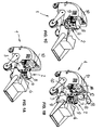
- numeral 1 generally designates an industrial vacuum cleaner appliance having a collection apparatus 2 for collecting sucked-up material according to the invention.
- the collection apparatus 2 may be disposed either within the vacuum cleaner appliance 1, in a special internal seat 3, as shown in Figures 1 a to 1 c, or external thereto, as shown in greater detail in Figure 2 .
- the collection apparatus 2 comprises a tank 4 having peripheral walls 5, a bottom 6 and an upper opening 7, opposite to the bottom 6, which is adapted to be closed by a removable lid 8, providing access to the interior compartment of the tank 4.
- the latter has hooks 9 for removable attachment thereof to a wall 10 of the vacuum cleaner appliance 1, which wall has suction means 11 associated therewith for creating a negative pressure in the tank 4 and a suction port 12 designed to be coupled to a corresponding inlet 13 formed in a support wall 4a of the tank 4, the latter wall being designed to face towards the wall 10 of the vacuum cleaner apparatus 1 when the tank 4 is in a mounted operating state.
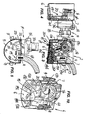
- the tank has separation means for separating the sucked up material from sucked air flows in a suction direction "A" defined between the inlet 13 and an outlet 14 from the tank 4.
- the separation means include separation means selected from wet separation means, generally referenced 15, and dry separation means, generally referenced 16 which, as described in greater detail below, can alternately and interchangeably mounted in said tank 4 using removable mounting means 17a associated with the tank 4 and 17b associated with the separation means 15 and 16 and designed to be coupled to the corresponding means 17a.
- wet separation means and “dry separation means” indicate that the former operate using a volume of liquid "VA”, typically water, loaded in the tank 4, to separate sucked up debris and particulate matter from sucked up air flows, whereas the latter use no liquid volume, and separation occurs either by gravity or using washable or replaceable filter means, namely a cylindrical filter 18.
- VA volume of liquid
- the terms “wet separation means” and “dry separation means” indicate that the former operate using a volume of liquid "VA”, typically water, loaded in the tank 4, to separate sucked up debris and particulate matter from sucked up air flows, whereas the latter use no liquid volume, and separation occurs either by gravity or using washable or replaceable filter means, namely a cylindrical filter 18.
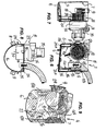
- the wet separation means 15 comprise, in greater detail, a siphon pipe, generally referenced 19, having a closed front portion and, as shown in Figure 13 , an open rear portion, which is designed to be sealed by the support wall 4a of the tank 4 when the separation means 15 are mounted therein.
- the pipe 19 comprises a first straight section 19a for conveying flows of air and debris and particulate matter suspended therein towards the bottom 6 of the tank 4, which section originates at the inlet 14 and dips into the water volume "VA", a second straight section 19b emerging from the water volume "VA” and oriented towards the suction means 11 and a central siphoning elbow section 19c.
- a connecting aperture 19d is formed at such central section 19c, and allows the water volume "VA" to flow into the pipe, thereby substantially entirely filling the third central elbow section 19c and partially filling the first inlet section 19a and the second outlet section 19b, as shown in Figure 3 , where the hatched area schematically represents the water volume "VA".
- a deflecting element 20 having such a shape as to divert the flows of sucked up air is provided at the outlet end of the section 19b, and emerges from the water volume "VA" towards the suction means 11.
- two respective flat ribs 21 and 22 extend from the first section 19a and the second section 19b, to lie on a common plane and form respective hooks 23 and 24 designed for coupling with the mounting means 17a in the tank 4.
- These mounting means 17a include respective columns 25 and 26, integrally raising from the bottom 6 of the tank 4, which have respective longitudinal guide grooves 25a and 26a for slideably receiving the corresponding ribs 21 and 22 until the hooks 23 and 24 abut against and engage with the upper ends of the columns 25 and 26.
- the dry separation means 16 include a straight conveying pipe section 27 which, like in the case of the wet separation means, originates at the inlet 13 of the tank 4 and has a closed front portion and, as shown in Figure 11 , an open rear portion, which is designed for watertight connection with the support wall 4a of the tank 4, when the separation means 16 are mounted therein as an alternative to the separation means 15.
- the pipe section 27 extends towards the bottom 6 of the tank 4 to convey thereto the flows of air sucked up from the outside, and carrying sucked up debris and particulate matter suspended therein, which will be deposited on the bottom 6 mainly by gravity.
- the suction unit 11 When the vacuum cleaner appliance 1 is operating, the suction unit 11 maintains a negative pressure in the interior compartment of the tank 4 and the flows of sucked up air are directed towards the outlet 14 which is nevertheless equipped with the filter 18 that separates any particulate residues from the flows of air sucked up by the suction unit 1, before reintroducing it into the environment.
- the dry separation means 16 also have corresponding ribs extending outwards, namely a rib integral with the pipe section 27 and a rib 31 formed in a support 32 of the filter 18.
- the pipe section 27 and the support 32 are also joined together by a transverse element 33 which makes them mutually integral, and forms one piece therefrom.
- the ribs 30 and 31 are adapted to slidably engage in a corresponding one of the longitudinal grooves 25a and 26a and terminate with the hooks 23 and 24, as described above.
- the dry separation means 16 may be converted, if needed, into wet separation means, by loading the tank 4 with a sufficient water volume "VA" for surface water to be above the end of the pipe section 27 facing towards the bottom 6 and by fitting the filter 18 with a protective cover element 34, typically comprising a sponge sleeve that can block the passage of any water particles still suspended in the flows of sucked up air and directed towards the suction means 11.
- a protective cover element 34 typically comprising a sponge sleeve that can block the passage of any water particles still suspended in the flows of sucked up air and directed towards the suction means 11.
- the latter include a motor unit 35 with an axis of rotation "AR" extending towards the tank 4 and rotatably driving a fan 36 having a plurality of blades, not shown, passages being defined therebetween for the flows of purified air, which are directed outwards to be reintroduced into the environment.
- a motor unit 35 with an axis of rotation "AR" extending towards the tank 4 and rotatably driving a fan 36 having a plurality of blades, not shown, passages being defined therebetween for the flows of purified air, which are directed outwards to be reintroduced into the environment.
- the bottom 6 is inclined to the edge of the upper opening 7, with two inclinations, for spontaneous buildup of the collected debris in an area of the tank 4 located proximate to the connecting aperture 19d or of the lower end of the pipe section 27.
- a more comprehensive version of the collection apparatus includes the combination with a UV emitter device, having a bactericide action, as shown in Figures 1b and 1c and referenced 40.
- the emitter device is mounted in the seat 3, but the skilled person will appreciate that it can be also directly mounted to a wall of the collection apparatus or to the lid 8.
- the operation of the collection apparatus is as follows: whenever a user has to collect debris and particulate matter using the vacuum cleaner appliance 1 with the technique of wet collection and removal of sucked up materials, he/she will fit the tank 4, once it has been removed from the vacuum cleaner appliance 1, with the wet separation means 16.
- the separation means 15 of the wet separation version are appropriately positioned in the tank 4.
- the support wall 4a acts as a closing wall for the open rear portion of the pipe 19 and the central siphoning section 19c and the connecting aperture 19d touch lightly the bottom of the tank 4 in which the water volume "VA" is loaded to such a level as to substantially entirely fill both the central siphoning section 19c and the connecting aperture 19d.
- the tank 4 is mounted to the vacuum cleaner appliance 1 and fixed thereto by means of the hooks 9, with watertight connection between the port 12 and the inlet 13 and between the axis of rotation "AR" and an aperture 13a formed in the wall 4 for this purpose.
- the upper opening 7 of the tank 4 is closed by the lid 8 and the user may turn on the vacuum cleaner appliance 1 which will suck up materials from the outside and convey them with the sucked up air into the water volume "VA" contained in the tank 4 through the first section 19a of the pipe 19.
- Water bubbling causes the sucked up materials to separate from air flows in a traditional fashion and once air has been purified it flows into the section 19b of the pipe 19, from which it is conveyed towards the apertures formed between the blades of the fan 36.
- the bottom 6 is inclined for spontaneous buildup of the materials collected and separated from air, in a predetermined area of the tank 4 from which they may be easily discharged by removing it from the vacuum cleaner appliance 1.
- the user removes the tank 4, removes the lid 8 therefrom and replaces the wet separation means 15 contained therein with the dry separation means 16, which fit by their ribs 30 and 31 into the guide grooves 25a and 26a and come to watertight connection with the support wall 4a which closes their open rear sections.
- the user mounts the tank 4 back to the vacuum cleaner appliance 1 as described above, locks it and closes its upper opening 7 again by the lid 8.
- the sucked up air and the materials (debris and particulate matter) contained therein are diverted towards the bottom 6 by the pipe section 27, where the heavier ones progressively build up by gravity.
- the latter may be also converted into wet separation means by simply mounting the protective element 34 peripherally to the filter 18 and by loading the tank 4 with the water volume "VA" while taking care that the level is maintained slightly above the lower end of the pipe section 27, so as to bubble the air flows and sucked up materials in the water volume "VA".
- the protective element 34 may consist, for instance, of a sponge sleeve, which blocks on one side any water particles left after bubbling in suspension in the air flows directed to the filter 18 and the motor 36 and allows on the other side the passage of purified air that has to be reintroduced into the environment after purification.
- the invention was found to fulfill the intended objects, i.e. allowing collection of particulate matter and debris with two different methods in a single vacuum cleaner appliance.
Landscapes
- Engineering & Computer Science (AREA)
- Mechanical Engineering (AREA)
- Filters For Electric Vacuum Cleaners (AREA)
- Nozzles For Electric Vacuum Cleaners (AREA)
- Drying Of Solid Materials (AREA)
- Silicon Compounds (AREA)
Applications Claiming Priority (1)
| Application Number | Priority Date | Filing Date | Title |
|---|---|---|---|
| IT000116A ITMO20110116A1 (it) | 2011-05-17 | 2011-05-17 | Apparato di raccolta di materiali aspirati per apparecchi aspirapolvere |
Publications (4)
| Publication Number | Publication Date |
|---|---|
| EP2524641A2 true EP2524641A2 (fr) | 2012-11-21 |
| EP2524641A3 EP2524641A3 (fr) | 2013-02-20 |
| EP2524641B1 EP2524641B1 (fr) | 2016-07-06 |
| EP2524641B8 EP2524641B8 (fr) | 2017-01-04 |
Family
ID=44554333
Family Applications (1)
| Application Number | Title | Priority Date | Filing Date |
|---|---|---|---|
| EP12003845.0A Active EP2524641B8 (fr) | 2011-05-17 | 2012-05-15 | Appareil pour collecter des matériaux aspirés destinés à être utilisés dans des appareils d'aspirateur |
Country Status (4)
| Country | Link |
|---|---|
| US (1) | US9237835B2 (fr) |
| EP (1) | EP2524641B8 (fr) |
| ES (1) | ES2601816T3 (fr) |
| IT (1) | ITMO20110116A1 (fr) |
Cited By (1)
| Publication number | Priority date | Publication date | Assignee | Title |
|---|---|---|---|---|
| WO2015019080A1 (fr) * | 2013-08-06 | 2015-02-12 | Techtronic Floor Care Technology Limited | Accessoire de filtration d'eau |
Families Citing this family (3)
| Publication number | Priority date | Publication date | Assignee | Title |
|---|---|---|---|---|
| US9604343B2 (en) * | 2014-09-19 | 2017-03-28 | Daniel P Oksanen | Hydro-filtration unit with sanding heads |
| CN106595053B (zh) * | 2016-11-30 | 2019-03-08 | 叶岳青 | 一种防尘电热水瓶 |
| CN108378773B (zh) * | 2018-04-13 | 2020-09-08 | 曾子航 | 一种方便清理的居家用吸尘装置 |
Family Cites Families (7)
| Publication number | Priority date | Publication date | Assignee | Title |
|---|---|---|---|---|
| GB1542994A (en) * | 1976-11-24 | 1979-03-28 | Parise & Sons Inc | Dirt-collecting containers for vacuum cleaners |
| US4287635A (en) * | 1979-05-07 | 1981-09-08 | Jacobs Paul G | Wet and dry vacuum cleaner |
| US4251241A (en) * | 1979-07-05 | 1981-02-17 | Windsor Industries, Inc. | Cyclone-type aspirated separator for washing dirt-laden dry airstreams |
| US5192344A (en) * | 1991-09-10 | 1993-03-09 | Andre E. Thorn Bacon | Wet filter vacuum cleaner |
| US6440191B1 (en) | 2000-06-14 | 2002-08-27 | Shop Vac Corporation | Vacuum cleaner filter assembly |
| US20060010639A1 (en) * | 2004-07-14 | 2006-01-19 | Yuen Se K | Electro-optical vacuum cleaner |
| US20120311811A1 (en) * | 2011-06-09 | 2012-12-13 | Emerson Electric Co. | Wet/dry vacuum appliance, dust filtration attachment therefore, and methods of use |
-
2011
- 2011-05-17 IT IT000116A patent/ITMO20110116A1/it unknown
-
2012
- 2012-05-15 US US13/472,355 patent/US9237835B2/en active Active
- 2012-05-15 ES ES12003845.0T patent/ES2601816T3/es active Active
- 2012-05-15 EP EP12003845.0A patent/EP2524641B8/fr active Active
Non-Patent Citations (1)
| Title |
|---|
| None |
Cited By (1)
| Publication number | Priority date | Publication date | Assignee | Title |
|---|---|---|---|---|
| WO2015019080A1 (fr) * | 2013-08-06 | 2015-02-12 | Techtronic Floor Care Technology Limited | Accessoire de filtration d'eau |
Also Published As
| Publication number | Publication date |
|---|---|
| EP2524641B8 (fr) | 2017-01-04 |
| EP2524641A3 (fr) | 2013-02-20 |
| EP2524641B1 (fr) | 2016-07-06 |
| ITMO20110116A1 (it) | 2012-11-18 |
| ES2601816T3 (es) | 2017-02-16 |
| US20120291219A1 (en) | 2012-11-22 |
| US9237835B2 (en) | 2016-01-19 |
Similar Documents
| Publication | Publication Date | Title |
|---|---|---|
| US7584522B1 (en) | Vertical cyclonic vacuum assembly | |
| KR100392606B1 (ko) | 진공청소기의 사이클론 집진장치 | |
| CN108712875B (zh) | 用于真空吸尘器的集尘室及吸头 | |
| CN101420895B (zh) | 单级旋风式真空清洁器 | |
| EP3095366B1 (fr) | Système d'aspirateur | |
| EP2364630A2 (fr) | Appareil de nettoyage de surface | |
| JP2002051947A (ja) | 真空掃除機のサイクロン集塵装置 | |
| KR20060117001A (ko) | 진공청소기용 집진유니트 | |
| AU2004202211B2 (en) | Dust Collecting Apparatus for a Vacuum Cleaner having Two Cyclone Chambers | |
| AU2007234560A1 (en) | Upright vacuum cleaner using return current of discharging air | |
| EP1464265B1 (fr) | Aspirateur | |
| KR20060128388A (ko) | 진공 청소기 | |
| JP2006175202A (ja) | 真空清掃機の集塵装置 | |
| KR100601451B1 (ko) | 진공 청소기의 집진 유니트 | |
| US9237835B2 (en) | Collecting apparatus of sucked materials for vacuum cleaner appliances | |
| JP2010154940A (ja) | 掃除機 | |
| EP2835088B1 (fr) | Système de séparation pour aspirateurs humides | |
| JP3178433U (ja) | 気液分離構造、吸引ホース及び掃除機 | |
| KR20170046345A (ko) | 사이클론 집진장치 및 이를 포함하는 진공 청소기 | |
| EP1661499A2 (fr) | Structure collectrice de poussière pour aspirateur | |
| GB2341124A (en) | Suction cleaner | |
| KR100800655B1 (ko) | 건식 및 습식 이중필터방식 진공청소기 | |
| CN215914451U (zh) | 一种清洁设备的污水箱及清洁设备 | |
| KR101597228B1 (ko) | 습식 이물질수거조를 구비하는 진공청소기 | |
| KR20180131853A (ko) | 절삭유 흡입청소기의 액체회수 및 배수장치 |
Legal Events
| Date | Code | Title | Description |
|---|---|---|---|
| PUAI | Public reference made under article 153(3) epc to a published international application that has entered the european phase |
Free format text: ORIGINAL CODE: 0009012 |
|
| AK | Designated contracting states |
Kind code of ref document: A2 Designated state(s): AL AT BE BG CH CY CZ DE DK EE ES FI FR GB GR HR HU IE IS IT LI LT LU LV MC MK MT NL NO PL PT RO RS SE SI SK SM TR |
|
| AX | Request for extension of the european patent |
Extension state: BA ME |
|
| PUAL | Search report despatched |
Free format text: ORIGINAL CODE: 0009013 |
|
| AK | Designated contracting states |
Kind code of ref document: A3 Designated state(s): AL AT BE BG CH CY CZ DE DK EE ES FI FR GB GR HR HU IE IS IT LI LT LU LV MC MK MT NL NO PL PT RO RS SE SI SK SM TR |
|
| AX | Request for extension of the european patent |
Extension state: BA ME |
|
| RIC1 | Information provided on ipc code assigned before grant |
Ipc: A47L 5/22 20060101ALI20130111BHEP Ipc: A47L 9/10 20060101ALI20130111BHEP Ipc: A47L 9/12 20060101ALI20130111BHEP Ipc: A47L 9/18 20060101AFI20130111BHEP |
|
| 17P | Request for examination filed |
Effective date: 20130731 |
|
| RBV | Designated contracting states (corrected) |
Designated state(s): AL AT BE BG CH CY CZ DE DK EE ES FI FR GB GR HR HU IE IS IT LI LT LU LV MC MK MT NL NO PL PT RO RS SE SI SK SM TR |
|
| 17Q | First examination report despatched |
Effective date: 20141117 |
|
| GRAP | Despatch of communication of intention to grant a patent |
Free format text: ORIGINAL CODE: EPIDOSNIGR1 |
|
| INTG | Intention to grant announced |
Effective date: 20160119 |
|
| GRAS | Grant fee paid |
Free format text: ORIGINAL CODE: EPIDOSNIGR3 |
|
| GRAA | (expected) grant |
Free format text: ORIGINAL CODE: 0009210 |
|
| AK | Designated contracting states |
Kind code of ref document: B1 Designated state(s): AL AT BE BG CH CY CZ DE DK EE ES FI FR GB GR HR HU IE IS IT LI LT LU LV MC MK MT NL NO PL PT RO RS SE SI SK SM TR |
|
| REG | Reference to a national code |
Ref country code: GB Ref legal event code: FG4D |
|
| REG | Reference to a national code |
Ref country code: AT Ref legal event code: REF Ref document number: 810082 Country of ref document: AT Kind code of ref document: T Effective date: 20160715 Ref country code: CH Ref legal event code: EP |
|
| REG | Reference to a national code |
Ref country code: IE Ref legal event code: FG4D |
|
| REG | Reference to a national code |
Ref country code: DE Ref legal event code: R096 Ref document number: 602012020129 Country of ref document: DE |
|
| REG | Reference to a national code |
Ref country code: SE Ref legal event code: TRGR |
|
| REG | Reference to a national code |
Ref country code: NL Ref legal event code: MP Effective date: 20160706 |
|
| REG | Reference to a national code |
Ref country code: LT Ref legal event code: MG4D |
|
| GRAT | Correction requested after decision to grant or after decision to maintain patent in amended form |
Free format text: ORIGINAL CODE: EPIDOSNCDEC |
|
| RAP2 | Party data changed (patent owner data changed or rights of a patent transferred) |
Owner name: T.P.A. IMPEX S.P.A. |
|
| PG25 | Lapsed in a contracting state [announced via postgrant information from national office to epo] |
Ref country code: IS Free format text: LAPSE BECAUSE OF FAILURE TO SUBMIT A TRANSLATION OF THE DESCRIPTION OR TO PAY THE FEE WITHIN THE PRESCRIBED TIME-LIMIT Effective date: 20161106 Ref country code: FI Free format text: LAPSE BECAUSE OF FAILURE TO SUBMIT A TRANSLATION OF THE DESCRIPTION OR TO PAY THE FEE WITHIN THE PRESCRIBED TIME-LIMIT Effective date: 20160706 Ref country code: NL Free format text: LAPSE BECAUSE OF FAILURE TO SUBMIT A TRANSLATION OF THE DESCRIPTION OR TO PAY THE FEE WITHIN THE PRESCRIBED TIME-LIMIT Effective date: 20160706 Ref country code: LT Free format text: LAPSE BECAUSE OF FAILURE TO SUBMIT A TRANSLATION OF THE DESCRIPTION OR TO PAY THE FEE WITHIN THE PRESCRIBED TIME-LIMIT Effective date: 20160706 Ref country code: HR Free format text: LAPSE BECAUSE OF FAILURE TO SUBMIT A TRANSLATION OF THE DESCRIPTION OR TO PAY THE FEE WITHIN THE PRESCRIBED TIME-LIMIT Effective date: 20160706 Ref country code: NO Free format text: LAPSE BECAUSE OF FAILURE TO SUBMIT A TRANSLATION OF THE DESCRIPTION OR TO PAY THE FEE WITHIN THE PRESCRIBED TIME-LIMIT Effective date: 20161006 Ref country code: RS Free format text: LAPSE BECAUSE OF FAILURE TO SUBMIT A TRANSLATION OF THE DESCRIPTION OR TO PAY THE FEE WITHIN THE PRESCRIBED TIME-LIMIT Effective date: 20160706 |
|
| REG | Reference to a national code |
Ref country code: ES Ref legal event code: FG2A Ref document number: 2601816 Country of ref document: ES Kind code of ref document: T3 Effective date: 20170216 |
|
| PG25 | Lapsed in a contracting state [announced via postgrant information from national office to epo] |
Ref country code: PT Free format text: LAPSE BECAUSE OF FAILURE TO SUBMIT A TRANSLATION OF THE DESCRIPTION OR TO PAY THE FEE WITHIN THE PRESCRIBED TIME-LIMIT Effective date: 20161107 Ref country code: PL Free format text: LAPSE BECAUSE OF FAILURE TO SUBMIT A TRANSLATION OF THE DESCRIPTION OR TO PAY THE FEE WITHIN THE PRESCRIBED TIME-LIMIT Effective date: 20160706 Ref country code: GR Free format text: LAPSE BECAUSE OF FAILURE TO SUBMIT A TRANSLATION OF THE DESCRIPTION OR TO PAY THE FEE WITHIN THE PRESCRIBED TIME-LIMIT Effective date: 20161007 Ref country code: LV Free format text: LAPSE BECAUSE OF FAILURE TO SUBMIT A TRANSLATION OF THE DESCRIPTION OR TO PAY THE FEE WITHIN THE PRESCRIBED TIME-LIMIT Effective date: 20160706 |
|
| REG | Reference to a national code |
Ref country code: DE Ref legal event code: R097 Ref document number: 602012020129 Country of ref document: DE |
|
| PG25 | Lapsed in a contracting state [announced via postgrant information from national office to epo] |
Ref country code: EE Free format text: LAPSE BECAUSE OF FAILURE TO SUBMIT A TRANSLATION OF THE DESCRIPTION OR TO PAY THE FEE WITHIN THE PRESCRIBED TIME-LIMIT Effective date: 20160706 Ref country code: RO Free format text: LAPSE BECAUSE OF FAILURE TO SUBMIT A TRANSLATION OF THE DESCRIPTION OR TO PAY THE FEE WITHIN THE PRESCRIBED TIME-LIMIT Effective date: 20160706 |
|
| PLBE | No opposition filed within time limit |
Free format text: ORIGINAL CODE: 0009261 |
|
| STAA | Information on the status of an ep patent application or granted ep patent |
Free format text: STATUS: NO OPPOSITION FILED WITHIN TIME LIMIT |
|
| REG | Reference to a national code |
Ref country code: FR Ref legal event code: PLFP Year of fee payment: 6 |
|
| PG25 | Lapsed in a contracting state [announced via postgrant information from national office to epo] |
Ref country code: SM Free format text: LAPSE BECAUSE OF FAILURE TO SUBMIT A TRANSLATION OF THE DESCRIPTION OR TO PAY THE FEE WITHIN THE PRESCRIBED TIME-LIMIT Effective date: 20160706 Ref country code: SK Free format text: LAPSE BECAUSE OF FAILURE TO SUBMIT A TRANSLATION OF THE DESCRIPTION OR TO PAY THE FEE WITHIN THE PRESCRIBED TIME-LIMIT Effective date: 20160706 Ref country code: CZ Free format text: LAPSE BECAUSE OF FAILURE TO SUBMIT A TRANSLATION OF THE DESCRIPTION OR TO PAY THE FEE WITHIN THE PRESCRIBED TIME-LIMIT Effective date: 20160706 Ref country code: DK Free format text: LAPSE BECAUSE OF FAILURE TO SUBMIT A TRANSLATION OF THE DESCRIPTION OR TO PAY THE FEE WITHIN THE PRESCRIBED TIME-LIMIT Effective date: 20160706 Ref country code: BG Free format text: LAPSE BECAUSE OF FAILURE TO SUBMIT A TRANSLATION OF THE DESCRIPTION OR TO PAY THE FEE WITHIN THE PRESCRIBED TIME-LIMIT Effective date: 20161006 |
|
| 26N | No opposition filed |
Effective date: 20170407 |
|
| PG25 | Lapsed in a contracting state [announced via postgrant information from national office to epo] |
Ref country code: LU Free format text: LAPSE BECAUSE OF NON-PAYMENT OF DUE FEES Effective date: 20170531 Ref country code: SI Free format text: LAPSE BECAUSE OF FAILURE TO SUBMIT A TRANSLATION OF THE DESCRIPTION OR TO PAY THE FEE WITHIN THE PRESCRIBED TIME-LIMIT Effective date: 20160706 |
|
| PG25 | Lapsed in a contracting state [announced via postgrant information from national office to epo] |
Ref country code: MC Free format text: LAPSE BECAUSE OF FAILURE TO SUBMIT A TRANSLATION OF THE DESCRIPTION OR TO PAY THE FEE WITHIN THE PRESCRIBED TIME-LIMIT Effective date: 20160706 |
|
| REG | Reference to a national code |
Ref country code: IE Ref legal event code: MM4A |
|
| PG25 | Lapsed in a contracting state [announced via postgrant information from national office to epo] |
Ref country code: LU Free format text: LAPSE BECAUSE OF NON-PAYMENT OF DUE FEES Effective date: 20170515 |
|
| PG25 | Lapsed in a contracting state [announced via postgrant information from national office to epo] |
Ref country code: IE Free format text: LAPSE BECAUSE OF NON-PAYMENT OF DUE FEES Effective date: 20170515 |
|
| REG | Reference to a national code |
Ref country code: FR Ref legal event code: PLFP Year of fee payment: 7 |
|
| PG25 | Lapsed in a contracting state [announced via postgrant information from national office to epo] |
Ref country code: MT Free format text: LAPSE BECAUSE OF NON-PAYMENT OF DUE FEES Effective date: 20170515 |
|
| PG25 | Lapsed in a contracting state [announced via postgrant information from national office to epo] |
Ref country code: AL Free format text: LAPSE BECAUSE OF FAILURE TO SUBMIT A TRANSLATION OF THE DESCRIPTION OR TO PAY THE FEE WITHIN THE PRESCRIBED TIME-LIMIT Effective date: 20160706 |
|
| PG25 | Lapsed in a contracting state [announced via postgrant information from national office to epo] |
Ref country code: HU Free format text: LAPSE BECAUSE OF FAILURE TO SUBMIT A TRANSLATION OF THE DESCRIPTION OR TO PAY THE FEE WITHIN THE PRESCRIBED TIME-LIMIT; INVALID AB INITIO Effective date: 20120515 |
|
| PG25 | Lapsed in a contracting state [announced via postgrant information from national office to epo] |
Ref country code: CY Free format text: LAPSE BECAUSE OF NON-PAYMENT OF DUE FEES Effective date: 20160706 |
|
| PG25 | Lapsed in a contracting state [announced via postgrant information from national office to epo] |
Ref country code: MK Free format text: LAPSE BECAUSE OF FAILURE TO SUBMIT A TRANSLATION OF THE DESCRIPTION OR TO PAY THE FEE WITHIN THE PRESCRIBED TIME-LIMIT Effective date: 20160706 |
|
| PG25 | Lapsed in a contracting state [announced via postgrant information from national office to epo] |
Ref country code: TR Free format text: LAPSE BECAUSE OF FAILURE TO SUBMIT A TRANSLATION OF THE DESCRIPTION OR TO PAY THE FEE WITHIN THE PRESCRIBED TIME-LIMIT Effective date: 20160706 |
|
| P01 | Opt-out of the competence of the unified patent court (upc) registered |
Effective date: 20230523 |
|
| PGFP | Annual fee paid to national office [announced via postgrant information from national office to epo] |
Ref country code: SE Payment date: 20250314 Year of fee payment: 14 |
|
| PGFP | Annual fee paid to national office [announced via postgrant information from national office to epo] |
Ref country code: DE Payment date: 20250509 Year of fee payment: 14 |
|
| PGFP | Annual fee paid to national office [announced via postgrant information from national office to epo] |
Ref country code: ES Payment date: 20250609 Year of fee payment: 14 |
|
| PGFP | Annual fee paid to national office [announced via postgrant information from national office to epo] |
Ref country code: BE Payment date: 20250520 Year of fee payment: 14 |
|
| PGFP | Annual fee paid to national office [announced via postgrant information from national office to epo] |
Ref country code: FR Payment date: 20250509 Year of fee payment: 14 |
|
| PGFP | Annual fee paid to national office [announced via postgrant information from national office to epo] |
Ref country code: CH Payment date: 20250601 Year of fee payment: 14 |
|
| PGFP | Annual fee paid to national office [announced via postgrant information from national office to epo] |
Ref country code: AT Payment date: 20250508 Year of fee payment: 14 |
|
| PGFP | Annual fee paid to national office [announced via postgrant information from national office to epo] |
Ref country code: GB Payment date: 20260323 Year of fee payment: 15 |
|
| PGFP | Annual fee paid to national office [announced via postgrant information from national office to epo] |
Ref country code: IT Payment date: 20260320 Year of fee payment: 15 |