EP2524842B1 - Dispositif de fixation pour plaque de revêtement - Google Patents
Dispositif de fixation pour plaque de revêtement Download PDFInfo
- Publication number
- EP2524842B1 EP2524842B1 EP11166326.6A EP11166326A EP2524842B1 EP 2524842 B1 EP2524842 B1 EP 2524842B1 EP 11166326 A EP11166326 A EP 11166326A EP 2524842 B1 EP2524842 B1 EP 2524842B1
- Authority
- EP
- European Patent Office
- Prior art keywords
- tongues
- cladding plate
- receiving element
- insert
- fixing device
- Prior art date
- Legal status (The legal status is an assumption and is not a legal conclusion. Google has not performed a legal analysis and makes no representation as to the accuracy of the status listed.)
- Active
Links
Images



Classifications
-
- B—PERFORMING OPERATIONS; TRANSPORTING
- B60—VEHICLES IN GENERAL
- B60R—VEHICLES, VEHICLE FITTINGS, OR VEHICLE PARTS, NOT OTHERWISE PROVIDED FOR
- B60R19/00—Wheel guards; Radiator guards, e.g. grilles; Obstruction removers; Fittings damping bouncing force in collisions
- B60R19/56—Fittings damping bouncing force in truck collisions, e.g. bumpers; Arrangements on high-riding vehicles, e.g. lorries, for preventing vehicles or objects from running thereunder
- B60R19/565—Fittings damping bouncing force in truck collisions, e.g. bumpers; Arrangements on high-riding vehicles, e.g. lorries, for preventing vehicles or objects from running thereunder on vehicle sides
Definitions
- the present invention concerns a fixing device for a cladding plate on the undercarriage of a vehicle according to the preamble of claim 1.
- the undercarriages of heavy goods vehicles are frequently provided with lateral cladding plates between the axles. These claddings improve the appearance of the vehicle, but serve above all for safety purposes, as they provide underride protection. These lateral cladding plates are detachably suspended to ensure the vehicle undercarriage remains accessible for maintenance and repair purposes.
- the plates are often attached by means of suspensions disposed in pairs, each pair comprising a top and bottom suspension. Whilst the cladding plate can be swung away from the vehicle by its lower edge at the bottom suspension, and, in the outwardly pivoted position, can be removed, the top suspension comprises a manual-release lock which secures the plate in the position in which it is pivoted against the vehicle. In the locked position, the cladding plate cannot be swung out and removed, nor can it be released by accident.
- the cladding plate is simply hooked into the bottom suspension whilst the top suspension comprises a ratchet system in which the upper edge of the plate engages.
- This system is relatively simple and inexpensive in its construction, and the cladding plate can be removed without complication.
- pivoting-removable cladding plates are given in EP0619217 , DE10319440 , EP1026046 , JP8028546 , JP9030412 , JP9030413 and GB330889 , the latter discloses a fixing device for a cladding plate according to the preamble of claim 1.
- the cladding plate my be flexible, for example due to its constructive material and/or due to its large dimensions. Therefore, any misalignment may lead to malfunction of the ratchet system.
- a disengagement of the top suspension may happens during the vehicle motion, and there is also the danger, that the hook on the bottom suspension can become detached, for example, in the event of strong vibrations.
- the task of the invention is to improve the above-described prior art fixing devices in such a way that the cladding plate is held more securely, without rendering the removal of the plate more difficult.
- the top suspension comprises an insert which is attached either to the undercarriage on the vehicle side, or to the cladding plate, plus a receiving element for the insert, which is attached to the other component as the case may be, i.e. to the cladding plate or the undercarriage.
- the insert can be pressed into the receiving element as the cladding plate is pivoted against the vehicle.
- Insert and receiving element comprise centring means, that complement each other in their design so that the insert, when pressed into the receiving element, is centred, and can be locked in the receiving element in the centred position.
- a pressing-in direction is substantially tangential to the upper side of the cladding plate.
- the insert may be attached to the undercarriage and the receiving element may be attached to the cladding plate.
- the receiving element comprises a spring-loaded lock cooperating with a respective seat on the insert and such centring means are able to keep together the insert and the receiving element for preventing the disengagement of the spring-loaded lock from its respective seat.
- the centring means comprise on the receiving element two sheet-metal tongues defining a V according to a front view of the internal side of cladding plate, symmetrically disposed with respect to the spring-loaded lock, and further comprise on the insert two sheet-metal tongues disposed parallel to the upper surfaces of the aforementioned two sheet-metal tongues. Therefore, such tongues of the insert are interposed, along said engaging direction of the spring-loaded lock with respect to its seat, between the tongues of the receiving element and the body of the receiving element. This avoids any movement along said engaging direction leading to their reciprocal disengagement.
- the bottom suspension comprises a bearing, defining a longitudinal developing axis, parallel to the direction in which the vehicle travels, mounted on the vehicle side with a C-shaped cross-section with respect to said axis. Lying rotatably, according said axis, inside this bearing there is an axle with different cross-sections along said longitudinal axis of the axle. These cross-sections are dimensioned so that, in a first rotated position representing the position of the cladding plate when pivoted against the vehicle, the axle is held in place in the bearing and cannot therefore be released through the laterally open cross-section of the bearing. In a second rotated position representing the position of the cladding plate when swung away from the vehicle, the cross-section of the axle is small enough to pass through the free lateral opening of the bearing cross-section so that the cladding plate can be removed without problem.
- the cladding plate is attached using the same sequence in reverse, starting by orienting the plate so that it can slide with its smaller cross-section into the C-shaped bearing from the side and it is then pivoted against the vehicle until the lock of the top suspension can be closed. In this rotated position, the axle is held securely in the bearing.
- the advantage of the construction according to the invention is that the cladding plate cannot accidentally become unhooked from the bottom suspension when the cladding plate is in the position where it is pivoted against the vehicle.
- the bottom suspension is a conventional hook/shaft coupling.
- a bottom suspension of the first embodiment my be coupled with a top suspension of the second embodiment in order to assure a higher safety level.
- the sheet-metal tongues can be provided with buffer elements.
- these buffers may be made of rubber or an elastomer.
- the sheet tongues are themselves elastically deformable, for example sheet-metal tongues, preferably with shape memory.
- the insert of the top suspension and the bearing/axle of the bottom suspension are preferably connected by a rigid carrier and are formed as one piece with this latter.
- the insert and the bearing/axle can thus be parts of a single component which is fixed on the vehicle side to a corresponding assembly element.
- the fixing device 10 shown in Fig. 1 serves to fix a cladding plate 12 to the undercarriage 14 of a heavy goods vehicle, shown only partially in this Figure.
- Cladding plate 12 serves in particular as lateral cladding for an open space between a front and rear wheel axle of the heavy goods vehicle and functions as an underride protection to prevent other road users from penetrating this space in the event of an accident.
- the fixing device 10 comprises a vertical rigid carrier 16, which is flanged at the side to a flange 18 of an assembly element 20, which forms part of undercarriage 14.
- this assembly element 20 is a horizontal carrier mounted transversely in undercarriage 14, having a flange 18 at its ends for receiving fixing device 10.
- the fixing device 10 itself comprises a bottom suspension 22 and, preferably disposed directly above the latter, a top suspension 24 for releasable fixing cladding plate 12 to undercarriage 14.
- Bottom suspension 22 comprises a pivot mechanism to allow cladding plate 12 to be pivoted away from the vehicle, according to arrows A when the top suspension 24 is released. In the swung-away position shown in Fig. 3 , cladding plate 12 can be removed from bottom suspension 22.
- Top suspension 24 comprises a manual-release lock which secures cladding plate 12 in the vertical position in which it is pivoted against undercarriage 14. As will be described in more detail in the following, this lock can be activated by pressing cladding plate 12 against the undercarriage.
- top suspension 24 and bottom suspension 22 are rigidly attached to the ends of profile carrier 16 and are connected by the latter to undercarriage 14. Details of the structure of bottom suspension 22 will be described below with reference to Figures 5 - 8 .
- the bottom suspension 22 comprises a bearing 26, defining a longitudinal development axis X, and has a C-shaped cross-section with respect to said axis X disposed parallel to the direction of travel of the vehicle and perpendicular to the plane of cladding plate 12.
- This bearing means 26 forms a cylindrical surface, which is open on one side of the cylinder sleeve and at the ends of the cylinder. Therefore, this bearing means 26 are C-shaped cross-section with respect to said X axis, where the lateral opening is parallel to said X axis and faces cladding plate 12.
- axle 28 Lying rotatably inside bearing 26 there is an axle 28, which is attached to the lower portion of the inside of cladding plate 12, lying flush against this latter.
- axle 28 is provided on one side with a flat surface 30, which is flanged to cladding plate 12.
- Axle 28 is oriented according that said X axis which points in the direction of travel of the vehicle.
- Axle 28 has a central portion 32, whose circumference on the non-flat side of axle 28 is adapted to the C-shaped cross-section of bearing 26, i.e. it is shaped on this side like a cylinder sleeve which slides inside bearing 26 as axle 28 rotates. This is shown particularly clearly by comparing the side views of Figures 5 and 6 , which show different rotated positions of axle 28 in bearing 26 according to the arrows A. On both sides of this central portion 32 there are end sections 34, 36 of axle 28, with different cross-sections to that of the previously described central portion 32.
- end sections 34, 36 On the side facing the cladding plate 12, these end sections 34, 36 have the flat surface 30 against which cladding plate 12 rests with its rear side, as well as adjoining circular curves at top and bottom 38, 40, whose outer surfaces are contrived to slide on the inside of bearing 26. On the side furthest removed from cladding plate 12, however, end sections 34, 36 are distanced from the inside of bearing 26 and spring back against the curve of central portion 32.
- the cross-section of the end sections of 34, 36 of axle 28 is, on the side furthest from cladding plate 12, formed by surfaces 42, 44, 46 which are angled in relation to each other, of which the upper and lower surfaces 42 and 46 adjoin curves 38,40.
- the cross-section of end sections 34, 36 can be described as similar to a hexagon, with the provision that the two cross-section sides 38 and 40 of this hexagon which adjoin flat surface 30, are slightly curved.
- axle 28 means that in the direction parallel to flat surface 30, end sections 34, 36 of axle 28 have a longer cross-section than in any other diameter direction angularly offset in relation to this diameter direction. Whilst the direction of the largest diameter is designated by D1 in Fig. 5 , a diameter direction with a shorter cross-section is designated at D2. Diameter D2 extends from a side edge of edge sections 34, 36 connecting rear-side flat surface 30 and the lower curved side 40, to an opposite edge for separating two flat sides 42, 44 on the side of end sections 34, 36 furthest from cladding plate 12.
- Diameter D1 of end sections 34, 36 coincides with the largest inner diameter of C-shaped bearing 26, but is larger than the free side opening of bearing 26 so that axle 28, in the position shown in Fig. 5 , cannot be removed from bearing 26 from the side, i.e. perpendicular to diameter direction D1. If axle 28 is rotated inside bearing 26 so that the position shown in Fig. 6 is attained, end sections 34, 36 can pass, thanks to their smaller diameter D2, the free opening of bearing 26 in a direction angularly offset in relation to D1 and can be removed.
- central section 32 does not block the removal motion
- bearing 26 is provided on the upper side of the C-shaped border with an opening 49 (see Fig. 3 ), disposed transversally with respect to the X axle. Therefore, the longitudinal opening of the bearing 26 and such opening 49 define together substantially an upside-down T. The curve of central section 32 can slide through this opening 49 during removal as in the situation in Fig. 5 .
- a pivoting movement of cladding plate 12 around axle 28 is indicated by a double-headed arrow A.
- cladding plate 12 can be removed in the direction of arrow B by removing axle 28 from bearing 26.
- the movement during removal is also shown in Fig. 6 by arrows B and C.
- a vehicle light 50 attached to the side of profile carrier 16 facing cladding plate 12 there is a vehicle light 50, which, when cladding plate 12 is pivoted inwards, inserts itself into a corresponding opening 52, ensuring that it remains visible from the outside of the vehicle even when cladding plate 12 is in position.
- This light 50 is not important in relation to the present invention.
- the profile carrier 16, in his bottom portion comprises a couple of wings 16a and 16b, disposed perpendicularly with respect to the cladding plate 12 and also perpendicularly with respect to the X axis, which points in the direction defined by the vehicle travelling, when the plate is assembled to the vehicle.
- Such wings 16a and 16b comprise supporting shaft 90 disposed parallel to the cladding plate and to the X axis, preferably, cylindrical-shaped and covered with an elastomeric coating.
- the cladding plate 12 has, in a lower portion of the inside thereof, a hook 13, flanged to the cladding plate by means his flat portion.
- the hook When the cladding plate is connected to the vehicle, the hook is inserted between said wings and leant against the supporting shaft 90.
- the hook has, also with respect to said X axis a C-shaped cross-section, so as the plate can rotate on the supporting shaft 90.
- the internal width of the hook 13 is dimensioned so as the plate, when in closed position, does not vibrate.
- the top suspension 24 comprises an insert 54 mounted at the top end of profile carrier 16, which is intended to be inserted into the receiving element 56 mounted on cladding plate 12.
- the receiving element 56 When the cladding plate is in closed position, the receiving element 56 is disposed over the top end of the profile carrier 16, so as a portion of the insert element fits in the receiving element, frontally, i.e. according to the closing rotation of the cladding plate.
- Insert 54 and receiving element 56 complement each other in their design so that insert 54, when pressed against receiving element 56, is centred in the latter and can be locked in this centred position.
- the receiving element 56 itself is formed by an angled sheet-metal element, whilst insert 54 is formed on the top end of profile carrier 16.
- the positions of insert 54 and receiving element 56 on assembly element 20 or on cladding plate 12 can be exchanged so that receiving element 56 may also be contrived on the top end of profile carrier 16, whilst insert 54 is attached to the inside of cladding plate 12.
- Receiving element 56 carries, in a central position, a, spring-loaded lock 72, which can be manually pulled vertically upwards by a hook 74 so that the bottom end 76 of the spring-loaded lock 72 can be pulled upwards.
- reversible lock 72 on the receiving element 56 cooperates with the respective seat 78, on the insert 54, defining an engaging direction Y, which is substantially vertical, i.e. radial with respect to the cladding plate pivoting.
- receiving element 56 In the pulled-up position, receiving element 56, together with the top part of cladding plate 12, can be pivoted away from insert 54. Conversely, when cladding plate 12 is pressed against profile carrier 16 as insert 54 moves into receiving element 56, the bottom end 76 of the spring-loaded lock 72 slides over a pawl 78, see figure 2 , disposed on the top end of profile carrier 16. Spring-loaded lock 72 then engages behind pawl 78, thereby securing the position of insert 54 in receiving element 56. Cladding plate 12 can therefore be released by simply acting on spring-loaded lock 72 and subsequent pivoting away and removal.
- the insert 54 is formed from two horizontally distanced sheet-metal tongues 58, 60 which project upwards, substantially perpendicularly with respect to the X axis and the cladding plate, at the top end of profile carrier 16 and are slightly inclined in relation to each other towards the reciprocal approaching movement of the insert 54 and receiving element according to arrows A, so that sheet-metal tongues 58, 60 converge in the pressing-in direction, i.e. in the direction of receiving element 56.
- Receiving element 56 comprises two complementarily disposed sheet-metal tongues 62, 64 which extend from cladding plate 12 and point towards insert 54.
- Sheet-metal tongues 62, 64 of receiving element 56 diverge slightly contrary to the direction in which insert 54 is inserted into receiving element 56.
- sheet-metal tongues 58, 60 of insert 54 rests against sheet-metal tongues 62, 64 of receiving element 56, and insert 54 is automatically centred in receiving element 56 due to the inclined position of tongues 58, 60, 62, 64.
- the right tongue 60 of insert 54 slides inwards along the corresponding tongue 64- of receiving element 56 until the centred position is achieved.
- tongue 58 slides along tongue 62 into the centred position.
- rubber buffers 66 are disposed on the outside of sheet-metal tongues 58, 60.
- Sheet-metal tongues 58,60,62,64 may be slightly elastic to ensure a play-free fit.
- receiving element 56 further comprises more sheet-metal tongues 68, 70, preferably on its bottom edge which is essentially horizontal, but inclined slightly upwards relative to the horizontal plane.
- These sheet-metal tongues 68, 70 which may be disposed between or externally the above-described sheet-metal tongues 62, 64, are intended to run onto corresponding surface areas 80, 82 of the insert 56, which are also positioned at a slight angle and provided on their top surface with buffer elements 66.
- tongues 68, 70 slide onto surface areas 80, 82 so that a fixed and play-free fit of cladding plate 12 is achieved in relation to the position of suspensions 22 and 24.
- Corresponding tongues may be provided on insert 54 instead of surface areas 80 and 82.
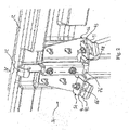
- the top suspension 24 comprises a receiving element 56 having two horizontally spaced tongues 91 and 92, symmetrically disposed with respect to the spring-loaded lock 72.
- tongues 91, 92 are substantially horizontal and perpendicular to the cladding plate 12.
- tongues are slightly downwards inclined towards the spring-loaded lock 72, in a V fashion.
- the top of the carrier 16 comprises two corresponding tongues 93, 94 disposed so as they are parallel to the upper surfaces of the tongues 91, 92. Rubber buffers 66 are disposed between the corresponding tongues 92/94 and 91/93.
- the tongues act as guidance so that insert 54 and receiving element 56 are reciprocally centred and the bottom end 76 of the spring-loaded lock 72 can engage the pawl 78.
- the resultants of the reaction forces exchanged between the tongues of the embodiment not forming part of the invention coincide with the reaction forces developed by said two couple of tongues 92/94 and 91/93 of the invention.
- the substantially horizontal tongues 93 and 94 of insert 54 are on the respective tongues 91 and 94 of receiving element 56.
- the tongues 91 and 92 of receiving element 56 are comprised between the tongues 93, 94 of the insert 54 and the body of the insert 54.
- the bottom suspension 22 prevents a vertical disengagement of the cladding plate from the vehicle, therefore such second embodiment of the top suspension is not strictly necessary, however this combination assures a high level of safety against the disengagement of the cladding plate from the vehicle.
- the features of the top suspension may be combined, for example by adding vertical tongues 62/58 and 60/64 to the top suspension.
Landscapes
- Engineering & Computer Science (AREA)
- Mechanical Engineering (AREA)
- Vehicle Body Suspensions (AREA)
- Body Structure For Vehicles (AREA)
- Springs (AREA)
- Vibration Prevention Devices (AREA)
- Clamps And Clips (AREA)
Claims (12)
- Dispositif de fixation (10) pour une plaque de revêtement (12) sur le train roulant (14) d'un véhicule, en particulier un poids lourd, avec une suspension inférieure (22) et disposée au-dessus de cette dernière, une suspension supérieure (24) pour fixer de manière amovible la plaque de revêtement (12) sur le train roulant (14), ladite plaque de revêtement (12) pouvant pivoter selon une rotation d'insertion / d'installation (A), par la suspension inférieure (22), la plaque de revêtement pivotant jusqu'à une position pivotée à distance, dans lequel la plaque de revêtement peut se découpler grâce à la suspension inférieure (22), et dont la suspension supérieure (24) comprend un verrouillage réversible (72) coopérant avec un siège (78) respectif le long d'une direction de mise en prise (Y), la suspension supérieure (24) comprenant :un insert (54) comprenant un tel siège (78) et étant fixé au train roulant (14) ou à la plaque de revêtement (12),un élément de réception (56) comprenant ledit verrouillable réversible (72) et étant fixé à la plaque de revêtement (12) ou au train roulant (14),l'insert (54) s'insérant dans l'élément de réception (56),caractérisé en ce que l'insert (54) et l'élément de réception (56) comprennent des moyens de centrage (92, 94), (91, 93) ayant au moins:des premières languettes en feuille (93, 94) raccordées à l'insert (54) et disposées sensiblement perpendiculairement à ladite direction de mise en prise (Y),desdeuxièmes languettesen feuille (91, 92) raccordées à l'élément de réception (56) afin d'être parallèles et complémentaires desdites premières languettes en feuille, lorsque l'insert (54) se monte sur l'élément de réception (56),lesdites première et seconde languettes coopérant entre elles, afin de guider ledit ajustement réciproque de l'insert et de l'élément de réception,et en ce que lesdites premières languettes (93, 94) sont intercalées, le long de ladite direction de mise en prise (Y), entre lesdites deuxièmes languettes (91, 92) et le corps de l'élément de réception (56) afin d'éviter tout mouvement le long de ladite direction de mise en prise (Y) menant à leur dégagement réciproque.
- Dispositif de fixation selon la revendication 1, caractérisé en ce que lesdites premières et deuxièmes languettes sont disposées symétriquement par rapport audit verrouillage réversible (72).
- Dispositif de fixation selon la revendication 2, caractérisé en ce que lesdites premières et deuxièmes languettes sont légèrement inclinées vers le bas vers le verrouillage réversible (72), à la manière d'un V.
- Dispositif de fixation selon la revendication 1, caractérisé en ce que:l'élément de réception (56) comprend deux troisièmes languettes en feuille (62, 64) disposées sensiblement verticalement et orientées vers l'extérieur, qui divergent contre la direction d'insertion (A), et en ce que:l'insert (54) comprend deux quatrièmes languettes métalliques (58, 60) complémentaires desdites troisièmes languettes, convergeant ainsi dans la direction d'insertion (A) pour s'appuyer contre lesdites troisièmes languettes en feuille (62, 64) de l'élément de réception (56), lorsque l'insert (54) est monté sur l'élément de réception (56).
- Dispositif de fixation selon l'une quelconque des revendications précédentes, caractérisé en ce que l'insert (54) est fixé sur le train roulant (14) et l'élément de réception (56) est fixé sur la plaque de revêtement (12).
- Dispositif de fixation selon l'une quelconque des revendications précédentes, caractérisé en ce qu'au moins l'une des languettes en feuille (91, 92, 93, 94) est prévue avec des éléments tampons élastiques (66).
- Dispositif de fixation selon l'une quelconque des revendications précédentes, caractérisé en ce que les languettes en feuille (91, 92, 93, 94) sont réalisés avec un matériau élastique.
- Dispositif de fixation selon l'une quelconque des revendications précédentes, caractérisé en ce que lesdites premières et deuxièmes, et lesdites troisièmes et quatrièmes languettes définissent un couplage sans jeu.
- Dispositif de fixation selon l'une quelconque des revendications précédentes, caractérisé en ce que le verrouillage réversible (72) comprend un verrouillage à ressort manuel.
- Dispositif de fixation selon l'une quelconque des revendications précédentes, caractérisé en ce que ladite suspension inférieure (22) comprend:un palier (26) définissant un axe de développement longitudinal (X), fixé sur le train roulant (14) et ayant une section transversale en forme de C selon ledit axe longitudinal (X), etun essieu (28) en rotation dans le palier (26), ledit essieu ayant différentes sections transversales (D1, D2) le long dudit axe longitudinal (X), de sorte que l'essieu (28) est retenu dans le palier (26) dans une première position entraînée en rotation, et peut être retiré du palier (26) sur un côté dans ladite position pivotée à distance.
- Dispositif de fixation selon l'une quelconque des revendications précédentes, caractérisé en ce que ladite suspension inférieure (22) comprend:un arbre de support (90) raccordé au véhicule et parallèle à la plaque de revêtement, lorsqu'il est monté sur le véhicule,un crochet (13) fixé par bride à la plaque de revêtement (12) au moyen de sa partie plate.
- Dispositif de fixation selon l'une quelconque des revendications précédentes, caractérisé en ce que l'insert (54) de la suspension supérieure (24) et le palier (26) ou l'arbre de support (90) de la suspension inférieure (22) sont raccordés par un support rigide (16) et sont formés d'un seul tenant avec ce dernier.
Priority Applications (7)
| Application Number | Priority Date | Filing Date | Title |
|---|---|---|---|
| EP11166326.6A EP2524842B1 (fr) | 2011-05-17 | 2011-05-17 | Dispositif de fixation pour plaque de revêtement |
| ES11166326.6T ES2487641T3 (es) | 2011-05-17 | 2011-05-17 | Dispositivo de fijación para una placa de protección |
| RU2013155862/11A RU2588370C2 (ru) | 2011-05-17 | 2012-05-17 | Устройство для крепления пластины обшивки |
| BR112013029522-8A BR112013029522B1 (pt) | 2011-05-17 | 2012-05-17 | dispositivo de fixação para uma placa de revestimento |
| CN201280024159.6A CN103562012B (zh) | 2011-05-17 | 2012-05-17 | 用于包覆板的固定设备 |
| AU2012258215A AU2012258215B2 (en) | 2011-05-17 | 2012-05-17 | Fixing device for a cladding plate |
| PCT/EP2012/059216 WO2012156493A1 (fr) | 2011-05-17 | 2012-05-17 | Dispositif de fixation pour une plaque de revêtement |
Applications Claiming Priority (1)
| Application Number | Priority Date | Filing Date | Title |
|---|---|---|---|
| EP11166326.6A EP2524842B1 (fr) | 2011-05-17 | 2011-05-17 | Dispositif de fixation pour plaque de revêtement |
Publications (2)
| Publication Number | Publication Date |
|---|---|
| EP2524842A1 EP2524842A1 (fr) | 2012-11-21 |
| EP2524842B1 true EP2524842B1 (fr) | 2014-05-07 |
Family
ID=44724608
Family Applications (1)
| Application Number | Title | Priority Date | Filing Date |
|---|---|---|---|
| EP11166326.6A Active EP2524842B1 (fr) | 2011-05-17 | 2011-05-17 | Dispositif de fixation pour plaque de revêtement |
Country Status (6)
| Country | Link |
|---|---|
| EP (1) | EP2524842B1 (fr) |
| CN (1) | CN103562012B (fr) |
| AU (1) | AU2012258215B2 (fr) |
| BR (1) | BR112013029522B1 (fr) |
| ES (1) | ES2487641T3 (fr) |
| WO (1) | WO2012156493A1 (fr) |
Families Citing this family (2)
| Publication number | Priority date | Publication date | Assignee | Title |
|---|---|---|---|---|
| SE537751C2 (sv) * | 2013-12-18 | 2015-10-13 | Scania Cv Ab | Arrangemang för att fästa en långsträckt sidoenhet till ettfordon |
| DE102017000394A1 (de) * | 2017-01-18 | 2018-07-19 | Daimler Ag | Verkleidungsanordnung zur Verkleidung eines Karosserieelements eines Fahrzeugs |
Family Cites Families (10)
| Publication number | Priority date | Publication date | Assignee | Title |
|---|---|---|---|---|
| GB330889A (en) * | 1929-02-18 | 1930-06-18 | George Albert Eastwood | Improvements relating to life-guards for motor omnibuses and other vehicles |
| JPS55160633A (en) * | 1979-05-29 | 1980-12-13 | Seiji Miwa | Device for protecting catching by vehicle's bite |
| GB8910747D0 (en) | 1989-05-10 | 1989-06-28 | Indalex Ltd | Improvements in or relating to extrusion presses |
| DE4309100C2 (de) | 1993-03-22 | 1998-05-07 | Daimler Benz Ag | Seitenverkleidung für Nutzfahrzeuge |
| JP3229524B2 (ja) | 1995-07-19 | 2001-11-19 | 日本車輌製造株式会社 | 鉄道車両の蓋体開閉装置 |
| DE19904386A1 (de) | 1999-02-03 | 2000-08-10 | Man Nutzfahrzeuge Ag | Versperrvorrichtung für Nutzfahrzeuge |
| DE10319440A1 (de) | 2003-04-30 | 2004-11-18 | Daimlerchrysler Ag | Nutzfahrzeug mit einem Unterfahrschutz-Staukasten |
| JP5035658B2 (ja) * | 2006-01-12 | 2012-09-26 | いすゞ自動車株式会社 | 車両のアンダーランプロテクタ取付構造 |
| CN201439333U (zh) * | 2009-08-12 | 2010-04-21 | 中集车辆(集团)有限公司 | 运输车及其侧面防护装置 |
| ES2524147T3 (es) * | 2010-03-02 | 2014-12-04 | Iveco Magirus Ag | Dispositivo de fijación para una placa de revestimiento de un vehículo |
-
2011
- 2011-05-17 EP EP11166326.6A patent/EP2524842B1/fr active Active
- 2011-05-17 ES ES11166326.6T patent/ES2487641T3/es active Active
-
2012
- 2012-05-17 BR BR112013029522-8A patent/BR112013029522B1/pt active IP Right Grant
- 2012-05-17 AU AU2012258215A patent/AU2012258215B2/en not_active Ceased
- 2012-05-17 WO PCT/EP2012/059216 patent/WO2012156493A1/fr not_active Ceased
- 2012-05-17 CN CN201280024159.6A patent/CN103562012B/zh not_active Expired - Fee Related
Also Published As
| Publication number | Publication date |
|---|---|
| CN103562012A (zh) | 2014-02-05 |
| WO2012156493A1 (fr) | 2012-11-22 |
| ES2487641T3 (es) | 2014-08-22 |
| AU2012258215B2 (en) | 2017-02-16 |
| RU2013155862A (ru) | 2015-06-27 |
| BR112013029522B1 (pt) | 2021-01-26 |
| AU2012258215A1 (en) | 2014-01-09 |
| BR112013029522A2 (pt) | 2017-01-24 |
| EP2524842A1 (fr) | 2012-11-21 |
| CN103562012B (zh) | 2016-05-18 |
Similar Documents
| Publication | Publication Date | Title |
|---|---|---|
| JP5947759B2 (ja) | カメラユニット | |
| US20080185808A1 (en) | Ramping Mudflap Assembly | |
| US10793073B2 (en) | Modular camera structure | |
| CA2899110C (fr) | Dispositif de verrou pour capot de vehicule professionnel | |
| EP2524842B1 (fr) | Dispositif de fixation pour plaque de revêtement | |
| EP2366609B1 (fr) | Dispositif de fixation d'une jupe de véhicule | |
| CA2866002A1 (fr) | Ensemble poignee | |
| JP2014518176A (ja) | 自動車のための側部保護デバイスおよび関連する自動車 | |
| US2838326A (en) | Semitrailer coupling-pin locking mechanism | |
| CN103182931A (zh) | 加油口盖结构 | |
| MX2014015845A (es) | Montaje de cinturon de seguridad para un dispositivo de computacion. | |
| US10239372B2 (en) | Equalizer for suspension system | |
| GB2503443A (en) | Vehicle lamp assembly | |
| CN214492804U (zh) | 一种汽车后护杠及汽车 | |
| CN109677440A (zh) | 转向架及具有其的车辆 | |
| US20170001597A1 (en) | Immobilizer device for a wheel | |
| KR101512029B1 (ko) | 고정 기능이 구비된 도어 힌지 | |
| US10850750B2 (en) | Vehicle draft key wear protector | |
| JP2018122631A (ja) | マーカーランプ用ステー | |
| CN207225195U (zh) | 一种前组合灯安装卡扣结构及前组合灯卡扣安装线路总成 | |
| CN214138531U (zh) | 钩尾框装置及铁路货车 | |
| JP2005343447A (ja) | 車両用番号板設置構造 | |
| JP7321656B2 (ja) | プレート取り付け構造 | |
| CN208730731U (zh) | 一种板簧安装限位固定结构 | |
| EP2517951B1 (fr) | Ensemble de base pour le support verrouillant d'une roue de secours |
Legal Events
| Date | Code | Title | Description |
|---|---|---|---|
| PUAI | Public reference made under article 153(3) epc to a published international application that has entered the european phase |
Free format text: ORIGINAL CODE: 0009012 |
|
| AK | Designated contracting states |
Kind code of ref document: A1 Designated state(s): AL AT BE BG CH CY CZ DE DK EE ES FI FR GB GR HR HU IE IS IT LI LT LU LV MC MK MT NL NO PL PT RO RS SE SI SK SM TR |
|
| AX | Request for extension of the european patent |
Extension state: BA ME |
|
| 17P | Request for examination filed |
Effective date: 20130520 |
|
| GRAP | Despatch of communication of intention to grant a patent |
Free format text: ORIGINAL CODE: EPIDOSNIGR1 |
|
| RIC1 | Information provided on ipc code assigned before grant |
Ipc: B62D 25/02 20060101ALI20131105BHEP Ipc: B60R 19/56 20060101AFI20131105BHEP |
|
| INTG | Intention to grant announced |
Effective date: 20131125 |
|
| GRAS | Grant fee paid |
Free format text: ORIGINAL CODE: EPIDOSNIGR3 |
|
| GRAA | (expected) grant |
Free format text: ORIGINAL CODE: 0009210 |
|
| AK | Designated contracting states |
Kind code of ref document: B1 Designated state(s): AL AT BE BG CH CY CZ DE DK EE ES FI FR GB GR HR HU IE IS IT LI LT LU LV MC MK MT NL NO PL PT RO RS SE SI SK SM TR |
|
| REG | Reference to a national code |
Ref country code: GB Ref legal event code: FG4D |
|
| REG | Reference to a national code |
Ref country code: AT Ref legal event code: REF Ref document number: 666366 Country of ref document: AT Kind code of ref document: T Effective date: 20140515 |
|
| REG | Reference to a national code |
Ref country code: IE Ref legal event code: FG4D |
|
| REG | Reference to a national code |
Ref country code: DE Ref legal event code: R096 Ref document number: 602011006695 Country of ref document: DE Effective date: 20140618 |
|
| REG | Reference to a national code |
Ref country code: SE Ref legal event code: TRGR |
|
| REG | Reference to a national code |
Ref country code: ES Ref legal event code: FG2A Ref document number: 2487641 Country of ref document: ES Kind code of ref document: T3 Effective date: 20140822 |
|
| REG | Reference to a national code |
Ref country code: NL Ref legal event code: T3 |
|
| REG | Reference to a national code |
Ref country code: AT Ref legal event code: MK05 Ref document number: 666366 Country of ref document: AT Kind code of ref document: T Effective date: 20140507 |
|
| REG | Reference to a national code |
Ref country code: LT Ref legal event code: MG4D |
|
| PG25 | Lapsed in a contracting state [announced via postgrant information from national office to epo] |
Ref country code: CY Free format text: LAPSE BECAUSE OF FAILURE TO SUBMIT A TRANSLATION OF THE DESCRIPTION OR TO PAY THE FEE WITHIN THE PRESCRIBED TIME-LIMIT Effective date: 20140507 Ref country code: GR Free format text: LAPSE BECAUSE OF FAILURE TO SUBMIT A TRANSLATION OF THE DESCRIPTION OR TO PAY THE FEE WITHIN THE PRESCRIBED TIME-LIMIT Effective date: 20140808 Ref country code: LT Free format text: LAPSE BECAUSE OF FAILURE TO SUBMIT A TRANSLATION OF THE DESCRIPTION OR TO PAY THE FEE WITHIN THE PRESCRIBED TIME-LIMIT Effective date: 20140507 Ref country code: IS Free format text: LAPSE BECAUSE OF FAILURE TO SUBMIT A TRANSLATION OF THE DESCRIPTION OR TO PAY THE FEE WITHIN THE PRESCRIBED TIME-LIMIT Effective date: 20140907 Ref country code: NO Free format text: LAPSE BECAUSE OF FAILURE TO SUBMIT A TRANSLATION OF THE DESCRIPTION OR TO PAY THE FEE WITHIN THE PRESCRIBED TIME-LIMIT Effective date: 20140807 Ref country code: FI Free format text: LAPSE BECAUSE OF FAILURE TO SUBMIT A TRANSLATION OF THE DESCRIPTION OR TO PAY THE FEE WITHIN THE PRESCRIBED TIME-LIMIT Effective date: 20140507 |
|
| PG25 | Lapsed in a contracting state [announced via postgrant information from national office to epo] |
Ref country code: PL Free format text: LAPSE BECAUSE OF FAILURE TO SUBMIT A TRANSLATION OF THE DESCRIPTION OR TO PAY THE FEE WITHIN THE PRESCRIBED TIME-LIMIT Effective date: 20140507 Ref country code: RS Free format text: LAPSE BECAUSE OF FAILURE TO SUBMIT A TRANSLATION OF THE DESCRIPTION OR TO PAY THE FEE WITHIN THE PRESCRIBED TIME-LIMIT Effective date: 20140507 Ref country code: HR Free format text: LAPSE BECAUSE OF FAILURE TO SUBMIT A TRANSLATION OF THE DESCRIPTION OR TO PAY THE FEE WITHIN THE PRESCRIBED TIME-LIMIT Effective date: 20140507 Ref country code: LV Free format text: LAPSE BECAUSE OF FAILURE TO SUBMIT A TRANSLATION OF THE DESCRIPTION OR TO PAY THE FEE WITHIN THE PRESCRIBED TIME-LIMIT Effective date: 20140507 Ref country code: AT Free format text: LAPSE BECAUSE OF FAILURE TO SUBMIT A TRANSLATION OF THE DESCRIPTION OR TO PAY THE FEE WITHIN THE PRESCRIBED TIME-LIMIT Effective date: 20140507 |
|
| PG25 | Lapsed in a contracting state [announced via postgrant information from national office to epo] |
Ref country code: PT Free format text: LAPSE BECAUSE OF FAILURE TO SUBMIT A TRANSLATION OF THE DESCRIPTION OR TO PAY THE FEE WITHIN THE PRESCRIBED TIME-LIMIT Effective date: 20140908 |
|
| REG | Reference to a national code |
Ref country code: CH Ref legal event code: PL |
|
| PG25 | Lapsed in a contracting state [announced via postgrant information from national office to epo] |
Ref country code: LI Free format text: LAPSE BECAUSE OF NON-PAYMENT OF DUE FEES Effective date: 20140531 Ref country code: SK Free format text: LAPSE BECAUSE OF FAILURE TO SUBMIT A TRANSLATION OF THE DESCRIPTION OR TO PAY THE FEE WITHIN THE PRESCRIBED TIME-LIMIT Effective date: 20140507 Ref country code: BE Free format text: LAPSE BECAUSE OF FAILURE TO SUBMIT A TRANSLATION OF THE DESCRIPTION OR TO PAY THE FEE WITHIN THE PRESCRIBED TIME-LIMIT Effective date: 20140507 Ref country code: DK Free format text: LAPSE BECAUSE OF FAILURE TO SUBMIT A TRANSLATION OF THE DESCRIPTION OR TO PAY THE FEE WITHIN THE PRESCRIBED TIME-LIMIT Effective date: 20140507 Ref country code: CH Free format text: LAPSE BECAUSE OF NON-PAYMENT OF DUE FEES Effective date: 20140531 Ref country code: RO Free format text: LAPSE BECAUSE OF FAILURE TO SUBMIT A TRANSLATION OF THE DESCRIPTION OR TO PAY THE FEE WITHIN THE PRESCRIBED TIME-LIMIT Effective date: 20140507 Ref country code: CZ Free format text: LAPSE BECAUSE OF FAILURE TO SUBMIT A TRANSLATION OF THE DESCRIPTION OR TO PAY THE FEE WITHIN THE PRESCRIBED TIME-LIMIT Effective date: 20140507 Ref country code: EE Free format text: LAPSE BECAUSE OF FAILURE TO SUBMIT A TRANSLATION OF THE DESCRIPTION OR TO PAY THE FEE WITHIN THE PRESCRIBED TIME-LIMIT Effective date: 20140507 |
|
| REG | Reference to a national code |
Ref country code: DE Ref legal event code: R097 Ref document number: 602011006695 Country of ref document: DE |
|
| REG | Reference to a national code |
Ref country code: IE Ref legal event code: MM4A |
|
| PLBE | No opposition filed within time limit |
Free format text: ORIGINAL CODE: 0009261 |
|
| STAA | Information on the status of an ep patent application or granted ep patent |
Free format text: STATUS: NO OPPOSITION FILED WITHIN TIME LIMIT |
|
| 26N | No opposition filed |
Effective date: 20150210 |
|
| PG25 | Lapsed in a contracting state [announced via postgrant information from national office to epo] |
Ref country code: IE Free format text: LAPSE BECAUSE OF NON-PAYMENT OF DUE FEES Effective date: 20140517 |
|
| REG | Reference to a national code |
Ref country code: DE Ref legal event code: R097 Ref document number: 602011006695 Country of ref document: DE Effective date: 20150210 |
|
| PG25 | Lapsed in a contracting state [announced via postgrant information from national office to epo] |
Ref country code: SI Free format text: LAPSE BECAUSE OF FAILURE TO SUBMIT A TRANSLATION OF THE DESCRIPTION OR TO PAY THE FEE WITHIN THE PRESCRIBED TIME-LIMIT Effective date: 20140507 |
|
| PG25 | Lapsed in a contracting state [announced via postgrant information from national office to epo] |
Ref country code: MT Free format text: LAPSE BECAUSE OF FAILURE TO SUBMIT A TRANSLATION OF THE DESCRIPTION OR TO PAY THE FEE WITHIN THE PRESCRIBED TIME-LIMIT Effective date: 20140507 |
|
| REG | Reference to a national code |
Ref country code: FR Ref legal event code: PLFP Year of fee payment: 6 |
|
| PG25 | Lapsed in a contracting state [announced via postgrant information from national office to epo] |
Ref country code: SM Free format text: LAPSE BECAUSE OF FAILURE TO SUBMIT A TRANSLATION OF THE DESCRIPTION OR TO PAY THE FEE WITHIN THE PRESCRIBED TIME-LIMIT Effective date: 20140507 Ref country code: MC Free format text: LAPSE BECAUSE OF FAILURE TO SUBMIT A TRANSLATION OF THE DESCRIPTION OR TO PAY THE FEE WITHIN THE PRESCRIBED TIME-LIMIT Effective date: 20140507 |
|
| REG | Reference to a national code |
Ref country code: DE Ref legal event code: R082 Ref document number: 602011006695 Country of ref document: DE Representative=s name: SCHWABE SANDMAIR MARX PATENTANWAELTE RECHTSANW, DE Ref country code: DE Ref legal event code: R082 Ref document number: 602011006695 Country of ref document: DE Representative=s name: SSM SANDMAIR PATENTANWAELTE RECHTSANWALT PARTN, DE |
|
| PG25 | Lapsed in a contracting state [announced via postgrant information from national office to epo] |
Ref country code: BG Free format text: LAPSE BECAUSE OF FAILURE TO SUBMIT A TRANSLATION OF THE DESCRIPTION OR TO PAY THE FEE WITHIN THE PRESCRIBED TIME-LIMIT Effective date: 20140507 |
|
| PG25 | Lapsed in a contracting state [announced via postgrant information from national office to epo] |
Ref country code: HU Free format text: LAPSE BECAUSE OF FAILURE TO SUBMIT A TRANSLATION OF THE DESCRIPTION OR TO PAY THE FEE WITHIN THE PRESCRIBED TIME-LIMIT; INVALID AB INITIO Effective date: 20110517 Ref country code: LU Free format text: LAPSE BECAUSE OF NON-PAYMENT OF DUE FEES Effective date: 20140517 Ref country code: TR Free format text: LAPSE BECAUSE OF FAILURE TO SUBMIT A TRANSLATION OF THE DESCRIPTION OR TO PAY THE FEE WITHIN THE PRESCRIBED TIME-LIMIT Effective date: 20140507 |
|
| REG | Reference to a national code |
Ref country code: FR Ref legal event code: PLFP Year of fee payment: 7 |
|
| REG | Reference to a national code |
Ref country code: FR Ref legal event code: PLFP Year of fee payment: 8 |
|
| PG25 | Lapsed in a contracting state [announced via postgrant information from national office to epo] |
Ref country code: MK Free format text: LAPSE BECAUSE OF FAILURE TO SUBMIT A TRANSLATION OF THE DESCRIPTION OR TO PAY THE FEE WITHIN THE PRESCRIBED TIME-LIMIT Effective date: 20140507 |
|
| PG25 | Lapsed in a contracting state [announced via postgrant information from national office to epo] |
Ref country code: AL Free format text: LAPSE BECAUSE OF FAILURE TO SUBMIT A TRANSLATION OF THE DESCRIPTION OR TO PAY THE FEE WITHIN THE PRESCRIBED TIME-LIMIT Effective date: 20140507 |
|
| P01 | Opt-out of the competence of the unified patent court (upc) registered |
Effective date: 20230522 |
|
| PGFP | Annual fee paid to national office [announced via postgrant information from national office to epo] |
Ref country code: SE Payment date: 20250228 Year of fee payment: 15 |
|
| PGFP | Annual fee paid to national office [announced via postgrant information from national office to epo] |
Ref country code: NL Payment date: 20250526 Year of fee payment: 15 |
|
| PGFP | Annual fee paid to national office [announced via postgrant information from national office to epo] |
Ref country code: DE Payment date: 20250528 Year of fee payment: 15 |
|
| PGFP | Annual fee paid to national office [announced via postgrant information from national office to epo] |
Ref country code: ES Payment date: 20250611 Year of fee payment: 15 |
|
| PGFP | Annual fee paid to national office [announced via postgrant information from national office to epo] |
Ref country code: IT Payment date: 20250512 Year of fee payment: 15 |
|
| PGFP | Annual fee paid to national office [announced via postgrant information from national office to epo] |
Ref country code: FR Payment date: 20250526 Year of fee payment: 15 |
|
| PGFP | Annual fee paid to national office [announced via postgrant information from national office to epo] |
Ref country code: GB Payment date: 20260304 Year of fee payment: 16 |