EP2525103A2 - Agencement de ventilateur - Google Patents
Agencement de ventilateur Download PDFInfo
- Publication number
- EP2525103A2 EP2525103A2 EP12003576A EP12003576A EP2525103A2 EP 2525103 A2 EP2525103 A2 EP 2525103A2 EP 12003576 A EP12003576 A EP 12003576A EP 12003576 A EP12003576 A EP 12003576A EP 2525103 A2 EP2525103 A2 EP 2525103A2
- Authority
- EP
- European Patent Office
- Prior art keywords
- fan
- front part
- back part
- holder
- arrangement according
- Prior art date
- Legal status (The legal status is an assumption and is not a legal conclusion. Google has not performed a legal analysis and makes no representation as to the accuracy of the status listed.)
- Granted
Links
Images


Classifications
-
- F—MECHANICAL ENGINEERING; LIGHTING; HEATING; WEAPONS; BLASTING
- F04—POSITIVE - DISPLACEMENT MACHINES FOR LIQUIDS; PUMPS FOR LIQUIDS OR ELASTIC FLUIDS
- F04D—NON-POSITIVE-DISPLACEMENT PUMPS
- F04D29/00—Details, component parts, or accessories
- F04D29/40—Casings; Connections of working fluid
- F04D29/52—Casings; Connections of working fluid for axial pumps
- F04D29/54—Fluid-guiding means, e.g. diffusers
- F04D29/541—Specially adapted for elastic fluid pumps
- F04D29/545—Ducts
-
- F—MECHANICAL ENGINEERING; LIGHTING; HEATING; WEAPONS; BLASTING
- F04—POSITIVE - DISPLACEMENT MACHINES FOR LIQUIDS; PUMPS FOR LIQUIDS OR ELASTIC FLUIDS
- F04D—NON-POSITIVE-DISPLACEMENT PUMPS
- F04D29/00—Details, component parts, or accessories
- F04D29/02—Selection of particular materials
- F04D29/023—Selection of particular materials especially adapted for elastic fluid pumps
-
- F—MECHANICAL ENGINEERING; LIGHTING; HEATING; WEAPONS; BLASTING
- F04—POSITIVE - DISPLACEMENT MACHINES FOR LIQUIDS; PUMPS FOR LIQUIDS OR ELASTIC FLUIDS
- F04D—NON-POSITIVE-DISPLACEMENT PUMPS
- F04D29/00—Details, component parts, or accessories
- F04D29/40—Casings; Connections of working fluid
- F04D29/52—Casings; Connections of working fluid for axial pumps
- F04D29/522—Casings; Connections of working fluid for axial pumps especially adapted for elastic fluid pumps
-
- F—MECHANICAL ENGINEERING; LIGHTING; HEATING; WEAPONS; BLASTING
- F05—INDEXING SCHEMES RELATING TO ENGINES OR PUMPS IN VARIOUS SUBCLASSES OF CLASSES F01-F04
- F05D—INDEXING SCHEME FOR ASPECTS RELATING TO NON-POSITIVE-DISPLACEMENT MACHINES OR ENGINES, GAS-TURBINES OR JET-PROPULSION PLANTS
- F05D2230/00—Manufacture
- F05D2230/60—Assembly methods
- F05D2230/68—Assembly methods using auxiliary equipment for lifting or holding
-
- F—MECHANICAL ENGINEERING; LIGHTING; HEATING; WEAPONS; BLASTING
- F05—INDEXING SCHEMES RELATING TO ENGINES OR PUMPS IN VARIOUS SUBCLASSES OF CLASSES F01-F04
- F05D—INDEXING SCHEME FOR ASPECTS RELATING TO NON-POSITIVE-DISPLACEMENT MACHINES OR ENGINES, GAS-TURBINES OR JET-PROPULSION PLANTS
- F05D2260/00—Function
- F05D2260/96—Preventing, counteracting or reducing vibration or noise
-
- F—MECHANICAL ENGINEERING; LIGHTING; HEATING; WEAPONS; BLASTING
- F05—INDEXING SCHEMES RELATING TO ENGINES OR PUMPS IN VARIOUS SUBCLASSES OF CLASSES F01-F04
- F05D—INDEXING SCHEME FOR ASPECTS RELATING TO NON-POSITIVE-DISPLACEMENT MACHINES OR ENGINES, GAS-TURBINES OR JET-PROPULSION PLANTS
- F05D2300/00—Materials; Properties thereof
- F05D2300/40—Organic materials
- F05D2300/43—Synthetic polymers, e.g. plastics; Rubber
Definitions
- the present invention relates to a fan assembly having at least one fan and at least one fan cover, which has at least one opening in which the fan is arranged and flows through the air supplied by the fan during operation of the fan.
- the present invention is therefore the object of developing a fan assembly of the type mentioned in such a way that it has a lower noise level during operation.
- fan cover may be partially or fully EPP or have EPP.
- the material EPP is expanded polypropylene, ie a polypropylene-based particle foam.
- This fan cover which consists of EPP or this, can be connected, for example, with the foamed housing of the device, in particular with the inner container or elsewhere by fasteners.
- the attachment of the fan cover by means of a bayonet lock in the housing or on the inner container.
- the fan cover for example, form the cover of a cooling air duct in which an evaporator is located.
- the fan assembly further comprises at least one fan holder, which is arranged on the fan cover and in turn carries the fan.
- This fan holder may have at least two parts, namely a front part and a back part, wherein it is preferably provided that the fan motor between the front part and the back part is arranged.
- the front part and the back part of the fan holder are designed so that they are fixable to each other and / or can be fixed to the fan cover, preferably by a rotational movement of the two parts relative to each other. So it is conceivable, for example, first insert the front part or first the back part in the fan cover or in the opening, then the other part on and set and fix both parts by a rotational movement relative to each other and preferably also to the fan cover. This is a very simple assembly or a very simple assembly of the entire fan assembly possible. Additional aids such as screw connections, etc. for fixing the fan bracket to the fan cover are not required in this case.
- the front part and the back part of the fan mount on an identical diameter.
- the front part and the back part have different diameters, so that the front part at least partially surrounds the back part or vice versa that the back part at least partially surrounds the front part.
- said breakthrough of the fan cover has a first region for receiving the front part and a second region for receiving the back part, wherein it is preferably provided that both regions have a different diameter.
- the diameters may also be identical and / or the fan holder may be constructed in one piece.
- the fan holder in particular the front part and the back part and / or said opening of the fan cover are round or circular in cross-section.
- the fan holder is arranged partially or completely in the opening of the fan cover.
- the fan holder is partially or completely made of plastic or plastic.
- the fan holder made of PS, that is, polystyrene or ABS, that is, acrylonitrile-butadiene-styrene or its copolymer.
- the said fastening means for fastening the fan cover to a further part of the refrigerator and / or freezer, in particular the foamed housing or the inner container may also consist of ABS or ABS.
- these are preferably designed as bayonet fixtures. It is z. B. holding means which have the shape of a screw in the broadest sense and which are inserted through recesses in the fan cover in corresponding receptacles on the housing or inner container and then rotated.
- This combination of materials achieves optimal noise reduction.
- Another advantage is that with the change in density of the EPP fan cover, the noise characteristics can be modified and easily adapted.
- the fan cover in particular in the edge region of said breakthrough of the fan cover has one or more recesses into which engage one or more projections, preferably tabs of the fan holder.
- said breakthrough of the fan cover has projections, which in turn engage in recesses of the fan bracket.
- the front part of the fan support prefferably has first means and for the back part of the fan support to have second means, the first means and the second means being designed such that they can be fixed to one another by rotational movement of the front part relative to the back part locked together.
- first means and the second means being designed such that they can be fixed to one another by rotational movement of the front part relative to the back part locked together.
- the fan holder has at least one annular portion, wherein the wing of the fan is accommodated in the part surrounded by the annular portion. This facilitates handling insofar as the fan blade is protected by the ring during assembly, etc.
- one or more damping elements are provided, which are located between the fan motor and the fan bracket, in particular between the fan motor and the front part and / or between the fan motor and the back part.
- damping elements may for example be arranged concentrically to the motor shaft and / or represent the connecting regions of the motor to the fan mounts.
- the damping elements may for example consist of rubber and engage in parts of the fan holder.
- the damping parts are not arranged on the fan motor, but on the fan bracket or its front part and back part and adjoin the fan motor in the mounted state.
- the fan motor is preferably exclusively via the aforementioned damping parts with the adjacent parts of the fan bracket in combination.
- the present invention further relates to a refrigerator and / or freezer with at least one fan assembly according to any one of claims 1 to 14.
- the fan assembly is in communication with the inner container of the device or with the foamed housing.
- a bayonet fixing means is provided for fixing the fan bracket on the device, which causes the desired fixation of the fan cover by a bayonet connection. For example, consider holding elements that may be screw-like, d. H. a shaft and a head and made of ABS.
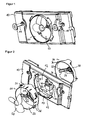
- FIG. 1 shows by the reference numeral 10, the fan cover of the fan assembly according to the invention.
- This fan cover is made of EPP and is built plate-shaped.
- a circular aperture 12 which extends through the fan cover.
- two right and left of the opening 12 arranged support members are marked, which have a helical shape and in its facing the fan cover 10 area means for bayonet-like attachment of the fan cover 10 z.
- B. on the inner container or elsewhere have a refrigerator and / or freezer. In their front area, they have a head adjoining the shaft, which is larger than the corresponding receiving bore in the fan cover.
- a tool holder for example a slot arranged by means of which the support members 16 can be rotated.
- FIG. 1 Like this further FIG. 1 and from FIG. 2 It is apparent in the opening 12 of the fan cover 10 is a fan holder 20, 30, in which the fan is arranged with its motor 40 and its driven by the motor 40 wings 50.
- FIG. 2 is an exploded view of the arrangement according to FIG. 1 seen. From this figure it can be seen that the aperture 12 has a first portion 13 with arranged in the edge region and circumferentially spaced recesses 14 and a second portion 15 of larger diameter, which is also provided in its edge region with circumferentially spaced recesses 16.
- the respective recesses 14, 16 are arranged so that they adjoin or overlap at least in a partial area.
- the first portion 13 of the opening 12 serves to receive the front part 20 of the fan support and the second portion 15 of the opening 12 is used for Recording the at least partially larger in diameter designed back portion 30 of the fan bracket.
- the fan bracket that is the front part 20 and / or the back part 30 are made of ABS or PS.
- the reference numeral 22 an annular portion of the front part 20 of the fan bracket is characterized, is received in the mounted state of the blade 50 of the fan. Furthermore, the front part 20 has three star-shaped webs 24, which extend from a central portion of the front part 20 to the outside, to the inside of the annular portion 22. In the central area where the webs 24 meet, there is a bore 28 for receiving the shaft 42 of the motor 40th
- the back part 30 of the fan bracket has an annular portion 32 from which three webs 34 run to each other. In the connection point of these webs 34 is a bore 38 in which a portion of the motor 40 is received, which in FIG. 2 is not apparent.
- the dimensions of the front part 20 and the back part 30 and the first portion 13 and the second portion 15 of the opening 12 are designed so that the front part 20 corresponds in its outer diameter approximately to the inner diameter of the first portion 13 and that the outer diameter of the back portion 30 in approximately corresponds to the inner diameter of the second section 15.
- the diameter of the second portion 15 is greater than that of the first portion 13 and the inner diameter of the back portion 30 at least partially larger than the outer diameter of the annular portion 22 of the front part 20, so that the front part 20 at least partially received in the back part 30 becomes. It is also conceivable that the back part 30 is received at least in regions in the front part 20.
- the fan support rear part 30 has at its outer periphery circumferentially spaced apart projections 36 which engage in corresponding recesses 16 of the second portion 15 of the opening 12.
- the projections 26 of the front part 20 are designed so that they have a receiving area for the projections 36 of the back part 30.
- This receiving region is designed so that by a rotational movement of the back part 30 relative to the front part 20, an engagement of the projections 36 takes place in the projections 26, so that both parts 20, 30 fixed, but releasably communicate with each other.
- the motor 40 on its side facing the webs 24 of the front part and to the webs 34 of the back part each have a damping element 44, which may be made of rubber.
- the fan motor 40 On the fan motor 40 are thus preferably two damping parts made of rubber, which engage in the corresponding parts of the fan holder and the front part 20 and the back part 30 made of ABS or PS. These parts are installed in the fan cover 10 made of EPP.
- the fan cover 10 is then preferably fastened in the housing by means of the principle of a bayonet closure.
- the housing has sometimes reproduced oscillations of the fan in devices known from the prior art as resonance body. This is greatly reduced by the new material pairings according to the present invention.
- the assembly and assembly of the fan assembly according to the invention is as follows:
- the front part 20 of the fan holder is inserted into the fan cover 10 made of EPP. Then, the fan motor 40 is positioned without the wing 50 in the inserted front part 20 with its two absorbers 44, of which only the front one is shown, in the front part 20. This condition is in FIG. 3 shown.
- the back portion 30 of the fan holder is then pushed into the designated opening of the front part 20 and the fan cover 10, or pushed over the front part 20 depending on the dimensions.
- the fastening tabs or projections 36 are positioned (different angles) so that no incorrect installation is possible.
- the projections 26 of the front part 20 thus engage in the depressions 14 of the first section 13 and the projections 36 of the back part 30 into the depressions 16 of the second section 15.
- cables can be, for example, the power cable or a control cable of the fan.
- Centering aids can also be located on the side of the fan holder with which the fan holder can be precisely positioned in the device.
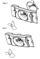
- FIG. 4 shows the state after installation of the back part 30 in the fan cover 10 and FIG. 5 the finished state of the fan assembly with mounted wing 50th
- FIG. 6 shows in an enlarged view the connection area between the front part 20 and the back part 30 with the respective projections 26, 36th
- FIG. 6 upper illustration shows the state of both parts relative to each other before twisting and thus before the locking of the back part 30
- FIG. 6 Lower illustration after rotation of the back part 30.
- the projection 36 of the back part 30 Before twisting the projection 36 of the back part 30 is adjacent to a recording of the projections 26 of the front part 20.
- the back part 30 Turned counterclockwise upper view, the projections 36 of the back part 30 are inserted into the receptacles of the projections 26 of the front part 20 and preferably locked therein.
- both parts 20, 30 are fixed relative to each other.
- the entire fan bracket is then also fixed in the opening 12 of the fan cover 10 and can neither fall forward or back out of this.
- FIG. 7 shows again in a view from behind the back part 30 relative to the front part 20 before the locking and FIG. 7 .
- the webs 24, 34 of the parts 20, 30 are aligned with each other.
- the present invention thus provides a mounting-friendly, noise-optimized and variable-use fan holder, wherein it is preferably provided that said fan cover made of EPP, the fan holder made of polystyrene or ABS and said bayonet-type fasteners or other fasteners made of ABS.
- said fan cover made of EPP
- the fan holder made of polystyrene or ABS
Landscapes
- Engineering & Computer Science (AREA)
- Mechanical Engineering (AREA)
- General Engineering & Computer Science (AREA)
- Structures Of Non-Positive Displacement Pumps (AREA)
- Jet Pumps And Other Pumps (AREA)
Applications Claiming Priority (1)
| Application Number | Priority Date | Filing Date | Title |
|---|---|---|---|
| DE102011102026A DE102011102026A1 (de) | 2011-05-19 | 2011-05-19 | Ventilatoranordnung |
Publications (3)
| Publication Number | Publication Date |
|---|---|
| EP2525103A2 true EP2525103A2 (fr) | 2012-11-21 |
| EP2525103A3 EP2525103A3 (fr) | 2014-11-26 |
| EP2525103B1 EP2525103B1 (fr) | 2017-09-20 |
Family
ID=46147230
Family Applications (1)
| Application Number | Title | Priority Date | Filing Date |
|---|---|---|---|
| EP12003576.1A Not-in-force EP2525103B1 (fr) | 2011-05-19 | 2012-05-08 | Agencement de ventilateur |
Country Status (3)
| Country | Link |
|---|---|
| EP (1) | EP2525103B1 (fr) |
| DE (1) | DE102011102026A1 (fr) |
| ES (1) | ES2652602T3 (fr) |
Families Citing this family (5)
| Publication number | Priority date | Publication date | Assignee | Title |
|---|---|---|---|---|
| DE102016217474A1 (de) | 2016-09-14 | 2018-03-15 | Vaillant Gmbh | Außeneinheit für eine Luft-Wasser-Wärmepumpe |
| DE102016218233A1 (de) * | 2016-09-22 | 2018-03-22 | Vaillant Gmbh | Außeneinheit für eine Luft-Wasser-Wärmepumpe |
| DE102019100109A1 (de) | 2019-01-04 | 2020-07-09 | Vaillant Gmbh | Effizienzerhöhung für Wärmepumpen-Lüftung |
| US11828520B2 (en) * | 2020-12-10 | 2023-11-28 | Electrolux Home Products, Inc. | Radial fan assembly |
| DE102023105992A1 (de) * | 2023-03-10 | 2024-09-12 | Stiebel Eltron Gmbh & Co. Kg | Warmwasserwärmepumpe |
Family Cites Families (13)
| Publication number | Priority date | Publication date | Assignee | Title |
|---|---|---|---|---|
| US4353680A (en) * | 1979-06-19 | 1982-10-12 | Tokyo Shibaura Denki Kabushiki Kaisha | Exhaust fan with removable face cover |
| FR2732524B1 (fr) * | 1995-04-03 | 1997-05-09 | Valeo Thermique Habitacle | Dispositif de fixation elastique d'un moteur electrique a l'interieur d'un boitier, notamment pour vehicule automobile |
| JP3388345B2 (ja) * | 1999-01-11 | 2003-03-17 | ミネベア株式会社 | 軸流ファンモータ |
| ES1048847Y (es) * | 2001-03-23 | 2002-06-01 | Electro Mecanica Cata S A | Soporte para un aparato impulsor axial de fluidos gaseosos. |
| WO2003078847A1 (fr) * | 2002-03-15 | 2003-09-25 | Arçelik A.S. | Carenage de ventilateur |
| DE10310973B3 (de) * | 2003-03-13 | 2005-06-02 | Erwin Müller GmbH | Lüftungsvorrichtung mit Schall- und Akustikkapselung |
| DE102004058724B4 (de) * | 2003-12-09 | 2018-11-15 | Denso Corporation | Wärmetauscher und Kühlmodul mit diesem |
| TWM275681U (en) * | 2005-05-13 | 2005-09-11 | Delta Electronics Inc | Fan housing |
| US20070098544A1 (en) * | 2005-11-02 | 2007-05-03 | Chung-Shu Wang | Device for enhancing performance of a fan assembly |
| DE202006008994U1 (de) * | 2006-06-06 | 2006-08-17 | Asia Vital Component Co., Ltd., Hsin Chuan | Rahmen von Ventilator |
| DE202007008216U1 (de) * | 2007-06-12 | 2007-10-04 | Tek-Chain Technology Co., Ltd. | Zusammenbaubarer Ventilatorrahmen |
| US20090211287A1 (en) * | 2008-02-25 | 2009-08-27 | Carrier Corporation | Modular condenser fan assembly |
| ES2356873B1 (es) * | 2009-07-29 | 2012-03-15 | Soler & Palau Research S.L. | Ventilador helicocentr�?fugo insonorizado. |
-
2011
- 2011-05-19 DE DE102011102026A patent/DE102011102026A1/de not_active Ceased
-
2012
- 2012-05-08 ES ES12003576.1T patent/ES2652602T3/es active Active
- 2012-05-08 EP EP12003576.1A patent/EP2525103B1/fr not_active Not-in-force
Non-Patent Citations (1)
| Title |
|---|
| None |
Also Published As
| Publication number | Publication date |
|---|---|
| ES2652602T3 (es) | 2018-02-05 |
| EP2525103A3 (fr) | 2014-11-26 |
| EP2525103B1 (fr) | 2017-09-20 |
| DE102011102026A1 (de) | 2012-11-22 |
Similar Documents
| Publication | Publication Date | Title |
|---|---|---|
| EP2525103B1 (fr) | Agencement de ventilateur | |
| EP2904333B1 (fr) | Élément de support pour ventilateur et ventilateur équipé d'un tel élément de support | |
| EP3064790A1 (fr) | Raccord enfichable avec element de couplage et pivot a rotule | |
| DE102012011848A1 (de) | Befestigungsanordnung | |
| EP2280173A1 (fr) | Appareil pour attacher le boitier d'un compresseur de refroidissement | |
| WO2012123206A1 (fr) | Dispositif de logement amortissant les vibrations | |
| WO2018028740A1 (fr) | Capsule insonorisante d'un bloc moteur de soufflerie d'un aspirateur, ainsi qu'aspirateur | |
| DE102012107571A1 (de) | Befestigungssystem zur Befestigung eines Verkleidungsteils | |
| EP3623715A2 (fr) | Système de boites murales pour un système d'aération | |
| DE102014116727A1 (de) | Lüftereinheit mit einem Lüftergehäuse | |
| DE102012100974A1 (de) | Lüfter und Anordnung aufweisend einen derartigen Lüfter | |
| EP2933495B1 (fr) | Fixation de ventilateur | |
| DE202005011482U1 (de) | Wärmerückgewinnungsgerät | |
| DE102007026611A1 (de) | Gebläse für ein Kraftfahrzeug | |
| DE102012100471A1 (de) | Belüftungsanordnung | |
| DE102012208935B4 (de) | Strömungsverdämmungselement, insbesondere zur Luftströmungsverdämmung in einem Luftkanalsystem eines Fahrzeugs | |
| DE102023002488A1 (de) | Befestigungsvorrichtung zur Befestigung eines Lidarsensors in einem Fahrzeug, Lidarsystem und Fahrzeug | |
| DE102016215571B4 (de) | Sitz mit einer Befestigungsanordnung eines Elektromotors | |
| EP2650994B1 (fr) | Agencement de prises pour canaux d'intégration d'appareils avec rail de maintien sur le fond du canal et canal d'intégration d'appareils comprenant un tel agencement de prises | |
| DE102007003635B4 (de) | Vorrichtungen zur Verbindung eines ersten Teils mit einem Träger | |
| DE19842512C1 (de) | Anordnung zur Installation einer Einbaukomponente in eine Wandung oder einen Hohlkörper | |
| EP1609229B1 (fr) | Montage d'un moteur sur un support | |
| DE102014116439A1 (de) | Vorrichtung zur Betätigung von Baugruppen mit einem walzenförmigen Körper | |
| EP1111285B1 (fr) | Support | |
| DE20318994U1 (de) | Torantriebsgehäuse |
Legal Events
| Date | Code | Title | Description |
|---|---|---|---|
| PUAI | Public reference made under article 153(3) epc to a published international application that has entered the european phase |
Free format text: ORIGINAL CODE: 0009012 |
|
| AK | Designated contracting states |
Kind code of ref document: A2 Designated state(s): AL AT BE BG CH CY CZ DE DK EE ES FI FR GB GR HR HU IE IS IT LI LT LU LV MC MK MT NL NO PL PT RO RS SE SI SK SM TR |
|
| AX | Request for extension of the european patent |
Extension state: BA ME |
|
| PUAL | Search report despatched |
Free format text: ORIGINAL CODE: 0009013 |
|
| AK | Designated contracting states |
Kind code of ref document: A3 Designated state(s): AL AT BE BG CH CY CZ DE DK EE ES FI FR GB GR HR HU IE IS IT LI LT LU LV MC MK MT NL NO PL PT RO RS SE SI SK SM TR |
|
| AX | Request for extension of the european patent |
Extension state: BA ME |
|
| RIC1 | Information provided on ipc code assigned before grant |
Ipc: F04D 29/54 20060101ALI20141021BHEP Ipc: F04D 29/02 20060101AFI20141021BHEP Ipc: F04D 29/52 20060101ALI20141021BHEP |
|
| 17P | Request for examination filed |
Effective date: 20150526 |
|
| 17Q | First examination report despatched |
Effective date: 20160210 |
|
| GRAP | Despatch of communication of intention to grant a patent |
Free format text: ORIGINAL CODE: EPIDOSNIGR1 |
|
| INTG | Intention to grant announced |
Effective date: 20170419 |
|
| GRAS | Grant fee paid |
Free format text: ORIGINAL CODE: EPIDOSNIGR3 |
|
| GRAA | (expected) grant |
Free format text: ORIGINAL CODE: 0009210 |
|
| AK | Designated contracting states |
Kind code of ref document: B1 Designated state(s): AL AT BE BG CH CY CZ DE DK EE ES FI FR GB GR HR HU IE IS IT LI LT LU LV MC MK MT NL NO PL PT RO RS SE SI SK SM TR |
|
| REG | Reference to a national code |
Ref country code: GB Ref legal event code: FG4D Free format text: NOT ENGLISH |
|
| REG | Reference to a national code |
Ref country code: CH Ref legal event code: EP |
|
| REG | Reference to a national code |
Ref country code: AT Ref legal event code: REF Ref document number: 930389 Country of ref document: AT Kind code of ref document: T Effective date: 20171015 |
|
| REG | Reference to a national code |
Ref country code: IE Ref legal event code: FG4D Free format text: LANGUAGE OF EP DOCUMENT: GERMAN |
|
| REG | Reference to a national code |
Ref country code: DE Ref legal event code: R096 Ref document number: 502012011291 Country of ref document: DE |
|
| REG | Reference to a national code |
Ref country code: NL Ref legal event code: MP Effective date: 20170920 |
|
| PG25 | Lapsed in a contracting state [announced via postgrant information from national office to epo] |
Ref country code: HR Free format text: LAPSE BECAUSE OF FAILURE TO SUBMIT A TRANSLATION OF THE DESCRIPTION OR TO PAY THE FEE WITHIN THE PRESCRIBED TIME-LIMIT Effective date: 20170920 Ref country code: NO Free format text: LAPSE BECAUSE OF FAILURE TO SUBMIT A TRANSLATION OF THE DESCRIPTION OR TO PAY THE FEE WITHIN THE PRESCRIBED TIME-LIMIT Effective date: 20171220 Ref country code: LT Free format text: LAPSE BECAUSE OF FAILURE TO SUBMIT A TRANSLATION OF THE DESCRIPTION OR TO PAY THE FEE WITHIN THE PRESCRIBED TIME-LIMIT Effective date: 20170920 Ref country code: SE Free format text: LAPSE BECAUSE OF FAILURE TO SUBMIT A TRANSLATION OF THE DESCRIPTION OR TO PAY THE FEE WITHIN THE PRESCRIBED TIME-LIMIT Effective date: 20170920 Ref country code: FI Free format text: LAPSE BECAUSE OF FAILURE TO SUBMIT A TRANSLATION OF THE DESCRIPTION OR TO PAY THE FEE WITHIN THE PRESCRIBED TIME-LIMIT Effective date: 20170920 |
|
| REG | Reference to a national code |
Ref country code: ES Ref legal event code: FG2A Ref document number: 2652602 Country of ref document: ES Kind code of ref document: T3 Effective date: 20180205 |
|
| REG | Reference to a national code |
Ref country code: LT Ref legal event code: MG4D |
|
| PG25 | Lapsed in a contracting state [announced via postgrant information from national office to epo] |
Ref country code: BG Free format text: LAPSE BECAUSE OF FAILURE TO SUBMIT A TRANSLATION OF THE DESCRIPTION OR TO PAY THE FEE WITHIN THE PRESCRIBED TIME-LIMIT Effective date: 20171220 Ref country code: GR Free format text: LAPSE BECAUSE OF FAILURE TO SUBMIT A TRANSLATION OF THE DESCRIPTION OR TO PAY THE FEE WITHIN THE PRESCRIBED TIME-LIMIT Effective date: 20171221 Ref country code: RS Free format text: LAPSE BECAUSE OF FAILURE TO SUBMIT A TRANSLATION OF THE DESCRIPTION OR TO PAY THE FEE WITHIN THE PRESCRIBED TIME-LIMIT Effective date: 20170920 Ref country code: LV Free format text: LAPSE BECAUSE OF FAILURE TO SUBMIT A TRANSLATION OF THE DESCRIPTION OR TO PAY THE FEE WITHIN THE PRESCRIBED TIME-LIMIT Effective date: 20170920 |
|
| PG25 | Lapsed in a contracting state [announced via postgrant information from national office to epo] |
Ref country code: NL Free format text: LAPSE BECAUSE OF FAILURE TO SUBMIT A TRANSLATION OF THE DESCRIPTION OR TO PAY THE FEE WITHIN THE PRESCRIBED TIME-LIMIT Effective date: 20170920 |
|
| PG25 | Lapsed in a contracting state [announced via postgrant information from national office to epo] |
Ref country code: PL Free format text: LAPSE BECAUSE OF FAILURE TO SUBMIT A TRANSLATION OF THE DESCRIPTION OR TO PAY THE FEE WITHIN THE PRESCRIBED TIME-LIMIT Effective date: 20170920 Ref country code: RO Free format text: LAPSE BECAUSE OF FAILURE TO SUBMIT A TRANSLATION OF THE DESCRIPTION OR TO PAY THE FEE WITHIN THE PRESCRIBED TIME-LIMIT Effective date: 20170920 Ref country code: CZ Free format text: LAPSE BECAUSE OF FAILURE TO SUBMIT A TRANSLATION OF THE DESCRIPTION OR TO PAY THE FEE WITHIN THE PRESCRIBED TIME-LIMIT Effective date: 20170920 |
|
| REG | Reference to a national code |
Ref country code: FR Ref legal event code: PLFP Year of fee payment: 7 |
|
| PG25 | Lapsed in a contracting state [announced via postgrant information from national office to epo] |
Ref country code: SK Free format text: LAPSE BECAUSE OF FAILURE TO SUBMIT A TRANSLATION OF THE DESCRIPTION OR TO PAY THE FEE WITHIN THE PRESCRIBED TIME-LIMIT Effective date: 20170920 Ref country code: EE Free format text: LAPSE BECAUSE OF FAILURE TO SUBMIT A TRANSLATION OF THE DESCRIPTION OR TO PAY THE FEE WITHIN THE PRESCRIBED TIME-LIMIT Effective date: 20170920 Ref country code: IS Free format text: LAPSE BECAUSE OF FAILURE TO SUBMIT A TRANSLATION OF THE DESCRIPTION OR TO PAY THE FEE WITHIN THE PRESCRIBED TIME-LIMIT Effective date: 20180120 Ref country code: SM Free format text: LAPSE BECAUSE OF FAILURE TO SUBMIT A TRANSLATION OF THE DESCRIPTION OR TO PAY THE FEE WITHIN THE PRESCRIBED TIME-LIMIT Effective date: 20170920 |
|
| REG | Reference to a national code |
Ref country code: DE Ref legal event code: R097 Ref document number: 502012011291 Country of ref document: DE |
|
| PLBE | No opposition filed within time limit |
Free format text: ORIGINAL CODE: 0009261 |
|
| STAA | Information on the status of an ep patent application or granted ep patent |
Free format text: STATUS: NO OPPOSITION FILED WITHIN TIME LIMIT |
|
| PG25 | Lapsed in a contracting state [announced via postgrant information from national office to epo] |
Ref country code: DK Free format text: LAPSE BECAUSE OF FAILURE TO SUBMIT A TRANSLATION OF THE DESCRIPTION OR TO PAY THE FEE WITHIN THE PRESCRIBED TIME-LIMIT Effective date: 20170920 |
|
| 26N | No opposition filed |
Effective date: 20180621 |
|
| PG25 | Lapsed in a contracting state [announced via postgrant information from national office to epo] |
Ref country code: MT Free format text: LAPSE BECAUSE OF FAILURE TO SUBMIT A TRANSLATION OF THE DESCRIPTION OR TO PAY THE FEE WITHIN THE PRESCRIBED TIME-LIMIT Effective date: 20170920 |
|
| PG25 | Lapsed in a contracting state [announced via postgrant information from national office to epo] |
Ref country code: SI Free format text: LAPSE BECAUSE OF FAILURE TO SUBMIT A TRANSLATION OF THE DESCRIPTION OR TO PAY THE FEE WITHIN THE PRESCRIBED TIME-LIMIT Effective date: 20170920 |
|
| REG | Reference to a national code |
Ref country code: CH Ref legal event code: PL |
|
| GBPC | Gb: european patent ceased through non-payment of renewal fee |
Effective date: 20180508 |
|
| REG | Reference to a national code |
Ref country code: BE Ref legal event code: MM Effective date: 20180531 |
|
| PG25 | Lapsed in a contracting state [announced via postgrant information from national office to epo] |
Ref country code: MC Free format text: LAPSE BECAUSE OF FAILURE TO SUBMIT A TRANSLATION OF THE DESCRIPTION OR TO PAY THE FEE WITHIN THE PRESCRIBED TIME-LIMIT Effective date: 20170920 |
|
| REG | Reference to a national code |
Ref country code: IE Ref legal event code: MM4A |
|
| PG25 | Lapsed in a contracting state [announced via postgrant information from national office to epo] |
Ref country code: CH Free format text: LAPSE BECAUSE OF NON-PAYMENT OF DUE FEES Effective date: 20180531 Ref country code: LI Free format text: LAPSE BECAUSE OF NON-PAYMENT OF DUE FEES Effective date: 20180531 |
|
| PG25 | Lapsed in a contracting state [announced via postgrant information from national office to epo] |
Ref country code: LU Free format text: LAPSE BECAUSE OF NON-PAYMENT OF DUE FEES Effective date: 20180508 |
|
| PG25 | Lapsed in a contracting state [announced via postgrant information from national office to epo] |
Ref country code: IE Free format text: LAPSE BECAUSE OF NON-PAYMENT OF DUE FEES Effective date: 20180508 Ref country code: GB Free format text: LAPSE BECAUSE OF NON-PAYMENT OF DUE FEES Effective date: 20180508 |
|
| PG25 | Lapsed in a contracting state [announced via postgrant information from national office to epo] |
Ref country code: BE Free format text: LAPSE BECAUSE OF NON-PAYMENT OF DUE FEES Effective date: 20180531 |
|
| REG | Reference to a national code |
Ref country code: AT Ref legal event code: MM01 Ref document number: 930389 Country of ref document: AT Kind code of ref document: T Effective date: 20180508 |
|
| PGFP | Annual fee paid to national office [announced via postgrant information from national office to epo] |
Ref country code: DK Payment date: 20190410 Year of fee payment: 12 Ref country code: IT Payment date: 20190531 Year of fee payment: 8 |
|
| PGFP | Annual fee paid to national office [announced via postgrant information from national office to epo] |
Ref country code: FR Payment date: 20190524 Year of fee payment: 8 |
|
| PG25 | Lapsed in a contracting state [announced via postgrant information from national office to epo] |
Ref country code: AT Free format text: LAPSE BECAUSE OF NON-PAYMENT OF DUE FEES Effective date: 20180508 |
|
| PG25 | Lapsed in a contracting state [announced via postgrant information from national office to epo] |
Ref country code: TR Free format text: LAPSE BECAUSE OF FAILURE TO SUBMIT A TRANSLATION OF THE DESCRIPTION OR TO PAY THE FEE WITHIN THE PRESCRIBED TIME-LIMIT Effective date: 20170920 |
|
| PG25 | Lapsed in a contracting state [announced via postgrant information from national office to epo] |
Ref country code: HU Free format text: LAPSE BECAUSE OF FAILURE TO SUBMIT A TRANSLATION OF THE DESCRIPTION OR TO PAY THE FEE WITHIN THE PRESCRIBED TIME-LIMIT; INVALID AB INITIO Effective date: 20120508 Ref country code: PT Free format text: LAPSE BECAUSE OF FAILURE TO SUBMIT A TRANSLATION OF THE DESCRIPTION OR TO PAY THE FEE WITHIN THE PRESCRIBED TIME-LIMIT Effective date: 20170920 |
|
| PG25 | Lapsed in a contracting state [announced via postgrant information from national office to epo] |
Ref country code: MK Free format text: LAPSE BECAUSE OF NON-PAYMENT OF DUE FEES Effective date: 20170920 Ref country code: CY Free format text: LAPSE BECAUSE OF FAILURE TO SUBMIT A TRANSLATION OF THE DESCRIPTION OR TO PAY THE FEE WITHIN THE PRESCRIBED TIME-LIMIT Effective date: 20170920 |
|
| PG25 | Lapsed in a contracting state [announced via postgrant information from national office to epo] |
Ref country code: AL Free format text: LAPSE BECAUSE OF FAILURE TO SUBMIT A TRANSLATION OF THE DESCRIPTION OR TO PAY THE FEE WITHIN THE PRESCRIBED TIME-LIMIT Effective date: 20170920 |
|
| PG25 | Lapsed in a contracting state [announced via postgrant information from national office to epo] |
Ref country code: FR Free format text: LAPSE BECAUSE OF NON-PAYMENT OF DUE FEES Effective date: 20200531 |
|
| REG | Reference to a national code |
Ref country code: ES Ref legal event code: FD2A Effective date: 20210928 |
|
| PG25 | Lapsed in a contracting state [announced via postgrant information from national office to epo] |
Ref country code: IT Free format text: LAPSE BECAUSE OF NON-PAYMENT OF DUE FEES Effective date: 20200508 |
|
| PG25 | Lapsed in a contracting state [announced via postgrant information from national office to epo] |
Ref country code: ES Free format text: LAPSE BECAUSE OF NON-PAYMENT OF DUE FEES Effective date: 20200509 |
|
| PGFP | Annual fee paid to national office [announced via postgrant information from national office to epo] |
Ref country code: DE Payment date: 20240523 Year of fee payment: 13 |
|
| REG | Reference to a national code |
Ref country code: DE Ref legal event code: R119 Ref document number: 502012011291 Country of ref document: DE |
|
| PG25 | Lapsed in a contracting state [announced via postgrant information from national office to epo] |
Ref country code: DE Free format text: LAPSE BECAUSE OF NON-PAYMENT OF DUE FEES Effective date: 20251202 |