EP2525157A2 - Verfahren zur Herstellung eines Heisswasserdurchsatzes, und entsprechendes System - Google Patents
Verfahren zur Herstellung eines Heisswasserdurchsatzes, und entsprechendes System Download PDFInfo
- Publication number
- EP2525157A2 EP2525157A2 EP12165306A EP12165306A EP2525157A2 EP 2525157 A2 EP2525157 A2 EP 2525157A2 EP 12165306 A EP12165306 A EP 12165306A EP 12165306 A EP12165306 A EP 12165306A EP 2525157 A2 EP2525157 A2 EP 2525157A2
- Authority
- EP
- European Patent Office
- Prior art keywords
- water
- temperature
- hot water
- ech
- flow
- Prior art date
- Legal status (The legal status is an assumption and is not a legal conclusion. Google has not performed a legal analysis and makes no representation as to the accuracy of the status listed.)
- Granted
Links
Images



Classifications
-
- F—MECHANICAL ENGINEERING; LIGHTING; HEATING; WEAPONS; BLASTING
- F24—HEATING; RANGES; VENTILATING
- F24D—DOMESTIC- OR SPACE-HEATING SYSTEMS, e.g. CENTRAL HEATING SYSTEMS; DOMESTIC HOT-WATER SUPPLY SYSTEMS; ELEMENTS OR COMPONENTS THEREFOR
- F24D17/00—Domestic hot-water supply systems
- F24D17/0005—Domestic hot-water supply systems using recuperation of waste heat
- F24D17/001—Domestic hot-water supply systems using recuperation of waste heat with accumulation of heated water
-
- F—MECHANICAL ENGINEERING; LIGHTING; HEATING; WEAPONS; BLASTING
- F24—HEATING; RANGES; VENTILATING
- F24D—DOMESTIC- OR SPACE-HEATING SYSTEMS, e.g. CENTRAL HEATING SYSTEMS; DOMESTIC HOT-WATER SUPPLY SYSTEMS; ELEMENTS OR COMPONENTS THEREFOR
- F24D17/00—Domestic hot-water supply systems
- F24D17/02—Domestic hot-water supply systems using heat pumps
-
- F—MECHANICAL ENGINEERING; LIGHTING; HEATING; WEAPONS; BLASTING
- F24—HEATING; RANGES; VENTILATING
- F24D—DOMESTIC- OR SPACE-HEATING SYSTEMS, e.g. CENTRAL HEATING SYSTEMS; DOMESTIC HOT-WATER SUPPLY SYSTEMS; ELEMENTS OR COMPONENTS THEREFOR
- F24D19/00—Details
- F24D19/10—Arrangement or mounting of control or safety devices
- F24D19/1006—Arrangement or mounting of control or safety devices for water heating systems
- F24D19/1051—Arrangement or mounting of control or safety devices for water heating systems for domestic hot water
- F24D19/1054—Arrangement or mounting of control or safety devices for water heating systems for domestic hot water the system uses a heat pump
-
- F—MECHANICAL ENGINEERING; LIGHTING; HEATING; WEAPONS; BLASTING
- F24—HEATING; RANGES; VENTILATING
- F24H—FLUID HEATERS, e.g. WATER OR AIR HEATERS, HAVING HEAT-GENERATING MEANS, e.g. HEAT PUMPS, IN GENERAL
- F24H15/00—Control of fluid heaters
- F24H15/10—Control of fluid heaters characterised by the purpose of the control
- F24H15/144—Measuring or calculating energy consumption
- F24H15/152—Forecasting future energy consumption
-
- F—MECHANICAL ENGINEERING; LIGHTING; HEATING; WEAPONS; BLASTING
- F24—HEATING; RANGES; VENTILATING
- F24H—FLUID HEATERS, e.g. WATER OR AIR HEATERS, HAVING HEAT-GENERATING MEANS, e.g. HEAT PUMPS, IN GENERAL
- F24H15/00—Control of fluid heaters
- F24H15/30—Control of fluid heaters characterised by control outputs; characterised by the components to be controlled
- F24H15/375—Control of heat pumps
- F24H15/38—Control of compressors of heat pumps
-
- F—MECHANICAL ENGINEERING; LIGHTING; HEATING; WEAPONS; BLASTING
- F24—HEATING; RANGES; VENTILATING
- F24D—DOMESTIC- OR SPACE-HEATING SYSTEMS, e.g. CENTRAL HEATING SYSTEMS; DOMESTIC HOT-WATER SUPPLY SYSTEMS; ELEMENTS OR COMPONENTS THEREFOR
- F24D2200/00—Heat sources or energy sources
- F24D2200/16—Waste heat
- F24D2200/20—Sewage water
-
- Y—GENERAL TAGGING OF NEW TECHNOLOGICAL DEVELOPMENTS; GENERAL TAGGING OF CROSS-SECTIONAL TECHNOLOGIES SPANNING OVER SEVERAL SECTIONS OF THE IPC; TECHNICAL SUBJECTS COVERED BY FORMER USPC CROSS-REFERENCE ART COLLECTIONS [XRACs] AND DIGESTS
- Y02—TECHNOLOGIES OR APPLICATIONS FOR MITIGATION OR ADAPTATION AGAINST CLIMATE CHANGE
- Y02B—CLIMATE CHANGE MITIGATION TECHNOLOGIES RELATED TO BUILDINGS, e.g. HOUSING, HOUSE APPLIANCES OR RELATED END-USER APPLICATIONS
- Y02B30/00—Energy efficient heating, ventilation or air conditioning [HVAC]
- Y02B30/18—Domestic hot-water supply systems using recuperated or waste heat
-
- Y—GENERAL TAGGING OF NEW TECHNOLOGICAL DEVELOPMENTS; GENERAL TAGGING OF CROSS-SECTIONAL TECHNOLOGIES SPANNING OVER SEVERAL SECTIONS OF THE IPC; TECHNICAL SUBJECTS COVERED BY FORMER USPC CROSS-REFERENCE ART COLLECTIONS [XRACs] AND DIGESTS
- Y02—TECHNOLOGIES OR APPLICATIONS FOR MITIGATION OR ADAPTATION AGAINST CLIMATE CHANGE
- Y02B—CLIMATE CHANGE MITIGATION TECHNOLOGIES RELATED TO BUILDINGS, e.g. HOUSING, HOUSE APPLIANCES OR RELATED END-USER APPLICATIONS
- Y02B30/00—Energy efficient heating, ventilation or air conditioning [HVAC]
- Y02B30/52—Heat recovery pumps, i.e. heat pump based systems or units able to transfer the thermal energy from one area of the premises or part of the facilities to a different one, improving the overall efficiency
Definitions
- the invention relates to a method for producing a hot water flow and an associated system. It finds particular application in the field of domestic hot water heating but also in the field of heating hot water used in industrial processes.
- Heat pumps using greywater are known as described in the patents FR2885406 (request 05 04597 ), or CN2779309 .
- Gray water is thus warm water generally derived from a mixture of stored hot water and distributed water that becomes gray due to the addition of soap, grease, food debris during the use which is done. They have a temperature higher than the temperature of the distributed city water or the distributed industrial water. They constitute throughout the year a source of heat at low temperature, typically around 32 ° C, provided to isolate the pipes and recover these waters closer to their source.
- Gray water is therefore a very suitable source for the production of hot water, this production can be performed using a heat pump, including a pump using a mixture zeotropic (that is to say boils at variable temperature while losing its initial composition) of refrigerants.
- a heat pump including a pump using a mixture zeotropic (that is to say boils at variable temperature while losing its initial composition) of refrigerants.
- the invention consists of a method for heating domestic hot water by a heat pump using a gray water storage stored in a recovery tank. More specifically, the invention consists in a method for producing a flow of domestic or industrial hot water, at a desired temperature from city water, by a heat pump comprising a condenser capable of heating the water of city by a condensing refrigerant and an evaporator in which circulates gray water able to evaporate said refrigerant, said gray water being stored upstream of said evaporator in a tank fed with warm water used obtained by mixing hot water and tap water, the method comprising a step of obtaining at least one temperature from the temperature of the city water and the temperature of the lukewarm water used, and being characterized in that it further comprises a step of adjusting the flow of gray water leaving said reservoir and entering said evaporator as a function of the at least one previously obtained temperature.
- the method comprises a step of obtaining each of the temperatures of the city water temperature and the temperature of the lukewarm water used.
- the step of adjusting the flow of gray water leaving said reservoir and entering said evaporator can be performed according to the two temperatures.
- the two parameters that can vary and have an impact on the heat transfer are taken into account.
- the ratio of the gray water flow rate to the flow rate of hot water to be produced is chosen to be equal to within 10 or 20% of the amplification ratio.
- a patch depending on other parameters can also be introduced without departing from the scope of the invention.
- the gray water flow is always greater than the city water flow to be heated because the flow amplification ratio is always greater than 1.
- the energy optimum is obtained when the ratio of the flow of gray water by the flow rate hot water to be produced is chosen equal to the amplification ratio.
- the method may include a preliminary determination of the hot water flow to be produced using a learning method, for example by genetic algorithm, using at least a history of the water level measured in said reservoir fed by lukewarm water used, thereby accessing repetitive variations in hot water needs over weeks and seasons. Thanks to this characteristic, the hot water needs are planned as closely as possible and the installation is as economical as possible. Thus, a regulator chooses the hot water production of the day to come, this being preferably the lowest possible. This then makes it possible to minimize the operating time of the heat pump and also minimize the heat losses of the hot water tank which may be only partially filled.
- a learning method for example by genetic algorithm
- the step of obtaining the lukewarm water temperature used consists of estimating this temperature from a gray water temperature stored in the reservoir and measured by a sensor, as well as from a leakage. theoretical between warm water as used and stored gray water.
- the step of obtaining the warm water temperature used comprises a step of direct measurement of this temperature.
- the method may comprise a step of verifying that the warm water temperature used is greater than a threshold temperature before storing this lukewarm water used in said tank.
- the method comprises a preliminary step of filling said reservoir with water at a target temperature of between plus and minus 8 K about the expected temperature for greywater, determined according to a use of said method.
- the invention also relates to a system for producing a flow of hot water at a desired temperature from city water by a heat pump in which gray water circulates, said gray water being stored upstream of said evaporator in a tank fed with warm water used obtained by mixing hot water and tap water, the system comprising means for obtaining at least one of the temperature of the water of city and the temperature of the warm water used and being characterized in that it also comprises means for adjusting the flow of gray water leaving said tank and entering said evaporator as a function of at least one temperature.
- the system comprises means for obtaining each of the temperatures of the city water temperature and the temperature of the lukewarm water used, thus taking into account the two parameters that may vary.
- the system comprises means for calculating a flow amplification ratio equal to the ratio of the temperature difference of the hot water and the city water and away from the temperatures. lukewarm water used and city water and means for adjusting the flow of gray water out of said tank and entering said evaporator so that the ratio between this flow rate and said flow of hot water to be produced is dependent said rate amplification report.
- the system is then remarkable in that the ratios of the city water flows to the condenser and the gray water to the evaporator are adapted to Extract the heat of the gray water as efficiently as possible to heat distributed city water and make it hot water.
- the system comprises a hot water tank after heating.
- the gray water tank is dimensioned, vis-à-vis gray water storage to maintain the evoked flow ratio.
- it preferably has a volume substantially equal to the volume of the hot water tank after heating multiplied by the rate of amplification ratio. The volume of gray water is then sufficient to meet the highest demand envisaged and is qualified for this as a "buffer stock".
- the constitution of a buffer stock in gray water and not in hot water is advantageous because, in general, the energy loss of a stock over time is proportional to the difference in the temperatures of the stock and the environment. As a result, with equal insulation quality, the energy loss is much lower for a buffer of gray water than for a buffer stock of hot water.
- hot water after heating is not stored.
- the refrigerant is a mixture of refrigerants whose condensation phase changes occur with a temperature difference of at least 12K between the beginning and the end of the condensation at constant pressure. .
- This additional feature improves the efficiency of the heat pump.
- electricity is also used at night, whose rate is lower than the day rate, to constitute the stock of hot water.
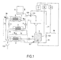
- this system comprises a tank 8 for storing the hot water produced by the system, also called hot water.
- domestic hot water is obtained by heating distributed city water, the temperature T EV of distributed city water being variable and in any case uncontrolled . It is produced by a heat pump 50, using the energy of a gray water storage stored in a tank 1.
- the heat pump 50 uses a zeotropic mixture of refrigerants. It mainly comprises an evaporator 3, a compressor 5 acting on the refrigerant, a condenser 4, an expansion valve 6 for the refrigerant, a town water heating circuit 12 and a gray water circuit 14. L Gray water, after transferring its heat, is discharged into a mains drainage.
- the gray water used by the heat pump 50 comes from the warm water used by users, residents or industrialists. For example, there is shown on the figure 1 , a sink 7 which is recovered gray water in a tank 1.
- the warm water was initially obtained, by means of a mixer 110, by mixing domestic hot water at temperature T ECH , originating, via a pipe 125, from the hot water tank 8, and distributed tap water ( cold), at temperature T EV , supplied via a pipe 11.
- T ECH domestic hot water
- T EV distributed tap water
- the mass M UTIL of warm water used, here in the sink 7, is equal to the sum made in the mixer 110 of the masses M ECH of hot water removed from the tank 8 and M EV distributed city water used.
- M UTIL M ECH + M EV
- the T UTIL temperature of the lukewarm water used is typically between 38 ° C (temperature of use for a shower) and 45 ° C (temperature of use for a dishwasher).
- the temperature T EG of the gray water stored in the tank 1 is substantially lower than the temperature of the warm water used T UTIL because of the losses in the sink, the shower or the dishwasher, which are typically of the order of 5 ° C.
- the temperature T EG of the gray water in the tank 1 is therefore generally between 33 ° C. and 40 ° C.
- the energy E UTIL of the warm water mass obtained at the mixer 110 is the sum of the energies E ECH and E EV of the mass of hot water and the mass of water. city water.
- Equation (2 ') is simplified by: M UTIL .
- T UTIL M ECH .
- T EV M ECH .
- This equation (5) is remarkable in that it allows to size the volume of the reservoir 1 of gray water depending on the volume of the tank 8 of domestic hot water.
- the mass ratio is defined at the mixing point.
- the thermal loss (difference between T UTIL and T ECH ) does not change the relationship, but requires additional power.
- the ratio of the volume of gray water to be stored to the volume of hot water to be stored varies between 1.4 and 1.51, which has the consequence that, in the of the construction, it is advantageous to build the reservoir 1 of gray water so that its volume is about 1.6 times larger than the volume of the tank 8 of hot water.
- the body of gray water stored in the tank 1 is destocked during the hours when the electric tariff is the lowest, generally at night, typically from 11 pm to 5 am.
- this flow rate evaluation is carried out by a regulator 17 capable of learning, for example by genetic algorithm, on the basis of the history of the consumption of domestic hot water at different days and hours of the past weeks.
- the regulator is based on the level and the temperature T EG of the gray water in the tank 1 which are measured by sensors 18 and 20. It also uses the temperature T EV of the mains water distributed at the arrival of town water 10, measured by a sensor 19.
- the regulator 17 defines the running time of the compressor 5 of the heat pump 50, and a gray water pump 141 controlling the inlet of the tap water distributed in the heat pump 50. It also defines the flow of city water treated by the heat pump by the opening time of a regulating valve 121 which controls the entry of tap water distributed in the heat pump.
- the sizing of the gray water tank 1 is established taking into account the maximum demand envisaged.
- the initial charge of gray water, constituting a buffer stock, is emptied only for this maximum demand, all the daily requirements being lower.
- the regulator 17 opens the regulating valve 121 of distributed city water supply with a flow M ECH and starts the gray water pump 141 to extract water.
- M EG M UTIL
- the ratio of flow rates M EG / M ECH is thus fixed equal to the ratio X m determined previously, by assimilating more T EG and T UTIL .
- the flow rate M EG of gray water is set at a value 51% higher than the flow rate M ECH of hot water.
- the heat pump 50 further comprises a first exchanger 2 for preheating the city water, configured to allow a first heat exchange between the water gray introduced by the pump 141 and the mains water dispensed, supplied by the regulating valve 121.
- the evaporator 3 and the condenser 4 of the heat pump 50 are dimensioned at design according to the ratio of flow rates M ECH and M EG of domestic hot water and gray water, considered constant (because varying less at 8% or 10% in this example as explained above).
- the flow rates are finally chosen constant, thus constituting a systematic operating point of the heat pump 50.
- the operating time of the heat pump 50 is controlled by the regulator 17, as a function of the quantity M ECH of hot water to be produced.
- the heat pump operates when the valves 121 and 141 are open.
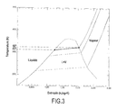
- the mixture of refrigerants which evaporates in the evaporator 3 and condenses in the condenser 4 is chosen to minimize the exergy losses by minimizing the temperature differences between the mixture of refrigerants and the gray water to be cooled by apart, and the city water to be heated on the other hand.
- the figure 3 is a temperature-mass entropy diagram of a mixture of refrigerants comprising the three fluids CO 2 / R-32 / R-152a in the respective mass compositions of 0.08 / 0.44 / 0.48, which under a pressure of 2.4 MPa, shows a start of condensation at 56.6 ° C and a condensation end at 43 ° C. These characteristics minimize irreversibilities for water that warms from about 30 to 55 ° C.
- blends can be designed that offer temperature slips between 15 and 25 K. These temperature slips can be adjusted by choosing refrigerants that have normal boiling temperatures.
- the normal boiling temperature T nb is the boiling temperature at atmospheric pressure. To obtain a slippage of the order of 12 to 25 K, it is necessary to choose fluids whose normal boiling temperatures are distant from the auters of the same order of magnitude.
- the mixture of CO 2 / R-32 / R-152a with respective compositions 0.08 / 0.44 / 0.48 has for example a slip of 13.6 K for a condensing pressure of 2.4 MPa.
- the use of such a zeotropic mixture of refrigerants in a heat pump significantly improves the coefficient of performance (ratio of the useful heat to the electrical power expended on the compressor).
- the storage of hot water in the tank 8 limits the size of the heat pump 50 and use electricity during the night.
- the temperature of distributed city water typically varies from +5 ° C to +20 ° C in a country like France between summer and winter and depending on the region.
- Flow rates measured on buildings indicate variations in hot water flow by a factor of 2 between the different days of the week. These two types of deviations are repetitive and not random.
- the running time of the heat pump 50 is directly proportional to the mass of hot water produced. A forecast closest to the needs therefore makes it possible to minimize the energy consumption of the heat pump 50.
- the regulator 17 defines the running time of the compressor 5 of the heat pump 50, the same running time for the gray water pump 141 and the flow of city water by the same opening time of the regulating valve 121.
- the initial dimensioning of the gray water tank 1 takes into account the maximum demand.
- the gray water buffer is emptied only for this maximum demand, all other daily requirements being lower.
- FIG 2 the system has been shown in a configuration where the heat pump 50 has operated to constitute a stock important buffer in the hot water tank 8, in anticipation of significant use in the short term.
- the method may include a preliminary step of verifying that the warm water temperature used T UTIL is greater than a threshold temperature before store this warm water used in the tank 1.
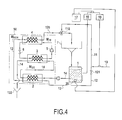
- FIG 4 there is shown a second embodiment of the invention, similar to the previous one, but for which no buffer stock of domestic hot water is constituted, the output of the heat pump 50 being connected directly to the mixer 110. there is therefore no hot water tank such as the reservoir 8 of the figures 1 and 2 .
- the heat pump 50 is sized to provide a larger hot water flow rate than in the previous embodiment.
- the hot water flow rate M ECH is measured continuously by a flow meter or a tap opening measurement.
- the measurements of the city water and gray water temperatures are carried out as in the previous embodiment.
- the gray water flow rate M EG is set so that it is equal to the hot water flow rate M EG multiplied by the flow amplification ratio X m .
- the evaluation of the warm water temperature used T UTIL is done by a measurement of this temperature T UTIL , for example by a sensor closer to the outlet of the sink 7, and whose average is measured on a period of several hours.
- a flow of hot water to be produced is determined.
- this is an average flow rate to be produced consistently over a period of time, for example during the night.
- the temperature T EV of the tap water dispensed by the sensor 19, and the temperature T EG of the greywater of the tank 1, are measured by the sensor 20.
- the regulator 17 calculates the rate amplification ratio X M , during a step 530. This step is performed on the basis of the prior consideration that the average value the temperature T UTIL of the warm water used in the mixer 110 is equal to the temperature of the stored gray water plus a loss value, for example 5 K.
- the regulator 17 sets the flow of gray water injected into the heat pump 50.
- the regulator 17 can directly fix the flow of gray water depending on the distributed city water temperature T EV and the gray water temperature T EG .
- This variant is indicated by the arrow (b).
- the gray water flow M EG is adjusted according to the temperatures T EV and T EG so that the flow rates M EG and M ECH are in a ratio, in fact, to the rate amplification ratio X M.
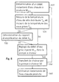
- figure 6 The flow is shown a variant of the method according to the invention, based on the installation of the figure 4 .
- steps 510 and 550 are identical to those of the process of figure 5 , with the exception of steps 510 and 550, replaced by steps 610 and 650.
- Step 610 is to determine an instantaneous flow rate of hot water to be produced, for example by measuring a valve opening that may vary with time, depending on the use made by the user.
- Step 650 consists of directly using the hot water produced by the heat pump 50 in step 540, without storage. In parallel with step 650, a new instantaneous flow rate value is calculated in a new step 610.
- figure 7 there is shown a variant of the invention that can be applied to one or the other of the two methods previously presented to figures 5 and 6 .
- a flow rate of hot water to be produced which can be an instantaneous or average flow rate, is determined.
- a step 720 the temperature of the distributed city water or the temperature of the greywater stored in the tank 1 is measured. On this basis, during a step 730, a flow control is carried out. of gray water injected into the heat pump. Finally, during a step 740, the heat pump heats the tap water using the energy extracted from the gray water and during a step 750 the hot water thus produced is stored. in the tank 8, or alternatively, it is used directly in the mixer 110.
Landscapes
- Engineering & Computer Science (AREA)
- Physics & Mathematics (AREA)
- Thermal Sciences (AREA)
- Chemical & Material Sciences (AREA)
- Combustion & Propulsion (AREA)
- Mechanical Engineering (AREA)
- General Engineering & Computer Science (AREA)
- Heat-Pump Type And Storage Water Heaters (AREA)
- Domestic Hot-Water Supply Systems And Details Of Heating Systems (AREA)
- Control Of Steam Boilers And Waste-Gas Boilers (AREA)
Priority Applications (1)
| Application Number | Priority Date | Filing Date | Title |
|---|---|---|---|
| PL12165306T PL2525157T3 (pl) | 2011-05-18 | 2012-04-24 | Sposób wytwarzania strumienia ciepłej wody i odnośnego systemu |
Applications Claiming Priority (1)
| Application Number | Priority Date | Filing Date | Title |
|---|---|---|---|
| FR1154316A FR2975472B1 (fr) | 2011-05-18 | 2011-05-18 | Procede de production d'un debit d'eau chaude et systeme associe |
Publications (4)
| Publication Number | Publication Date |
|---|---|
| EP2525157A2 true EP2525157A2 (de) | 2012-11-21 |
| EP2525157A3 EP2525157A3 (de) | 2017-02-15 |
| EP2525157B1 EP2525157B1 (de) | 2018-06-27 |
| EP2525157B8 EP2525157B8 (de) | 2019-03-20 |
Family
ID=45954545
Family Applications (1)
| Application Number | Title | Priority Date | Filing Date |
|---|---|---|---|
| EP12165306.7A Active EP2525157B8 (de) | 2011-05-18 | 2012-04-24 | Verfahren zur Herstellung eines Heisswasserdurchsatzes, und entsprechendes System |
Country Status (7)
| Country | Link |
|---|---|
| EP (1) | EP2525157B8 (de) |
| DK (1) | DK2525157T3 (de) |
| ES (1) | ES2690206T3 (de) |
| FR (1) | FR2975472B1 (de) |
| PL (1) | PL2525157T3 (de) |
| PT (1) | PT2525157T (de) |
| TR (1) | TR201814022T4 (de) |
Cited By (4)
| Publication number | Priority date | Publication date | Assignee | Title |
|---|---|---|---|---|
| WO2014135147A1 (de) * | 2013-03-07 | 2014-09-12 | Wolfgang Jaske | Verfahren und vorrichtung zur rückgewinnung von energie von einem zu kühlenden wärmeenergieträger |
| CN104214952A (zh) * | 2014-09-12 | 2014-12-17 | 上海电力学院 | 淋浴废水余热利用装置 |
| FR3041420A1 (fr) * | 2015-09-22 | 2017-03-24 | Commissariat Energie Atomique | Dispositif de production d'eau chaude sanitaire par recuperation de chaleur des eaux usees, une installation et un procede de production associe |
| CN114877554A (zh) * | 2022-06-23 | 2022-08-09 | 深圳市奥科德冷冻系统有限公司 | 一种存储生物样本超低温冷库制冷系统 |
Citations (5)
| Publication number | Priority date | Publication date | Assignee | Title |
|---|---|---|---|---|
| FR504597A (fr) | 1919-10-06 | 1920-07-08 | Marius Jean Baptiste Barbarou | Dispositif de roulement |
| CN2779309Y (zh) | 2005-02-02 | 2006-05-10 | 邵才宝 | 一种热回收型热泵式生活热水器 |
| FR2885406A1 (fr) | 2005-05-04 | 2006-11-10 | Armines Ass Loi De 1901 | Pompe a chaleur pour le chauffage de l'eau chaude sanitaire utilisant la chaleur residuelle des eaux usees. |
| CN101504190A (zh) | 2009-03-11 | 2009-08-12 | 黄邦兴 | 废热水余热回收型热泵热水系统 |
| FR2942299A1 (fr) | 2009-02-16 | 2010-08-20 | Ass Pour La Rech Et Le Dev De | Systeme de distribution d'eau chaude comportant un ballon d'accumulation sous pression d'un gaz |
Family Cites Families (2)
| Publication number | Priority date | Publication date | Assignee | Title |
|---|---|---|---|---|
| FR2935784B1 (fr) * | 2008-09-05 | 2013-02-08 | Alain Moure | Systeme de chauffage avec recuperation de chaleur des eaux usees par un circuit secondaire |
| BE1019045A5 (nl) * | 2009-10-16 | 2012-02-07 | Chanse | Werkwijze om warmte van een afvalstroom toe te voegen aan een vloeistofstroom en installatie daarvoor. |
-
2011
- 2011-05-18 FR FR1154316A patent/FR2975472B1/fr active Active
-
2012
- 2012-04-24 TR TR2018/14022T patent/TR201814022T4/en unknown
- 2012-04-24 ES ES12165306.7T patent/ES2690206T3/es active Active
- 2012-04-24 EP EP12165306.7A patent/EP2525157B8/de active Active
- 2012-04-24 PT PT12165306T patent/PT2525157T/pt unknown
- 2012-04-24 DK DK12165306.7T patent/DK2525157T3/en active
- 2012-04-24 PL PL12165306T patent/PL2525157T3/pl unknown
Patent Citations (5)
| Publication number | Priority date | Publication date | Assignee | Title |
|---|---|---|---|---|
| FR504597A (fr) | 1919-10-06 | 1920-07-08 | Marius Jean Baptiste Barbarou | Dispositif de roulement |
| CN2779309Y (zh) | 2005-02-02 | 2006-05-10 | 邵才宝 | 一种热回收型热泵式生活热水器 |
| FR2885406A1 (fr) | 2005-05-04 | 2006-11-10 | Armines Ass Loi De 1901 | Pompe a chaleur pour le chauffage de l'eau chaude sanitaire utilisant la chaleur residuelle des eaux usees. |
| FR2942299A1 (fr) | 2009-02-16 | 2010-08-20 | Ass Pour La Rech Et Le Dev De | Systeme de distribution d'eau chaude comportant un ballon d'accumulation sous pression d'un gaz |
| CN101504190A (zh) | 2009-03-11 | 2009-08-12 | 黄邦兴 | 废热水余热回收型热泵热水系统 |
Cited By (5)
| Publication number | Priority date | Publication date | Assignee | Title |
|---|---|---|---|---|
| WO2014135147A1 (de) * | 2013-03-07 | 2014-09-12 | Wolfgang Jaske | Verfahren und vorrichtung zur rückgewinnung von energie von einem zu kühlenden wärmeenergieträger |
| CN104214952A (zh) * | 2014-09-12 | 2014-12-17 | 上海电力学院 | 淋浴废水余热利用装置 |
| FR3041420A1 (fr) * | 2015-09-22 | 2017-03-24 | Commissariat Energie Atomique | Dispositif de production d'eau chaude sanitaire par recuperation de chaleur des eaux usees, une installation et un procede de production associe |
| WO2017050623A1 (fr) * | 2015-09-22 | 2017-03-30 | Commissariat A L'energie Atomique Et Aux Energies Alternatives | Dispositif de production d'eau chaude sanitaire par récupération de chaleur des eaux usées, une installation et un procédé de production associé |
| CN114877554A (zh) * | 2022-06-23 | 2022-08-09 | 深圳市奥科德冷冻系统有限公司 | 一种存储生物样本超低温冷库制冷系统 |
Also Published As
| Publication number | Publication date |
|---|---|
| EP2525157B8 (de) | 2019-03-20 |
| PL2525157T4 (pl) | 2019-06-28 |
| TR201814022T4 (en) | 2018-11-21 |
| PL2525157T3 (pl) | 2019-06-28 |
| PT2525157T (pt) | 2018-11-06 |
| EP2525157A3 (de) | 2017-02-15 |
| FR2975472B1 (fr) | 2013-06-21 |
| EP2525157B1 (de) | 2018-06-27 |
| ES2690206T3 (es) | 2018-11-19 |
| FR2975472A1 (fr) | 2012-11-23 |
| DK2525157T3 (en) | 2018-10-15 |
Similar Documents
| Publication | Publication Date | Title |
|---|---|---|
| FR3041420B1 (fr) | Dispositif de production d'eau chaude sanitaire par recuperation de chaleur des eaux usees, une installation et un procede de production associe | |
| EP2525157B1 (de) | Verfahren zur Herstellung eines Heisswasserdurchsatzes, und entsprechendes System | |
| EP3404334B1 (de) | Energiespeicherverfahren und -anlage, die einen wasserboiler umfasst | |
| WO2013004972A1 (fr) | Systeme d'echange thermique et procede de regulation d'une puissance thermique developpee par un tel systeme d'echange thermique | |
| FR2994730A1 (fr) | Systeme hybride de production d'eau chaude sanitaire a pompe a chaleur et chaudiere. | |
| FR2995979A1 (fr) | Installation de chauffe-eau sanitaire a fonction de chauffage | |
| FR3101134A1 (fr) | Machine thermodynamique de type thermofrigopompe multisources et procede de fonctionnement | |
| EP1963758A1 (de) | Kälteerzeugungssolareinheit für eine klimaanlage, wärmeerzeugungssolareinheit, vorrichtungen und steuerverfahren dafür | |
| EP1724531B1 (de) | Vorrichtung und Verfahren zur Erzeugung von heißem Brauchwasser unter Ausnutzung von Abwasserrestwärme | |
| EP3489588A1 (de) | Brauchwasser-heizsystem | |
| FR2924746A1 (fr) | Installation de production d'electricite a partir d'energie solaire. | |
| FR2954472A1 (fr) | Chauffe-eau solaire a double sonde thermique | |
| WO2012062992A1 (fr) | Chaudière à coefficient de performance élevé | |
| WO2010043829A2 (fr) | Pompe a chaleur | |
| EP0228307A1 (de) | Verfahren zur Raumheizung und heissen Trinkwasserzubereitung unter Benutzung von Erdwärme aus unterirdischen Brunnen | |
| FR2813117A1 (fr) | Procede et installation de chauffage a partir de l'energie solaire | |
| EP3339729A1 (de) | Dampferzeugungsvorrichtung, die eine wärmequelle niedriger temperatur umfasst | |
| FR2934890A1 (fr) | Installation de pompe a chaleur pour le chauffage d'un fluide. | |
| EP2775221A1 (de) | Durchlauf- und Temperaturregulierung eines Durchlauferhitzers zur Warmwassererzeugung | |
| EP3581853B1 (de) | Wärmeübertragungsmodul für die erzeugung von warmwasser | |
| FR2966565A1 (fr) | Installation de production d’eau chaude sanitaire pour habitation collective et procede de mise en oeuvre d’une telle installation | |
| FR2937410A1 (fr) | Pompe a chaleur | |
| FR3125867A1 (fr) | Système de stockage et de chauffage thermodynamique à pilotage optimisé | |
| EP4113015B1 (de) | Anlage zur warmwasserbereitung | |
| FR2999684A1 (fr) | Dispositif de preparation d'eau chaude sanitaire |
Legal Events
| Date | Code | Title | Description |
|---|---|---|---|
| PUAI | Public reference made under article 153(3) epc to a published international application that has entered the european phase |
Free format text: ORIGINAL CODE: 0009012 |
|
| 17P | Request for examination filed |
Effective date: 20120424 |
|
| AK | Designated contracting states |
Kind code of ref document: A2 Designated state(s): AL AT BE BG CH CY CZ DE DK EE ES FI FR GB GR HR HU IE IS IT LI LT LU LV MC MK MT NL NO PL PT RO RS SE SI SK SM TR |
|
| AX | Request for extension of the european patent |
Extension state: BA ME |
|
| PUAL | Search report despatched |
Free format text: ORIGINAL CODE: 0009013 |
|
| AK | Designated contracting states |
Kind code of ref document: A3 Designated state(s): AL AT BE BG CH CY CZ DE DK EE ES FI FR GB GR HR HU IE IS IT LI LT LU LV MC MK MT NL NO PL PT RO RS SE SI SK SM TR |
|
| AX | Request for extension of the european patent |
Extension state: BA ME |
|
| RIC1 | Information provided on ipc code assigned before grant |
Ipc: F24D 17/02 20060101ALI20170110BHEP Ipc: F24D 17/00 20060101AFI20170110BHEP |
|
| REG | Reference to a national code |
Ref country code: DE Ref legal event code: R079 Ref document number: 602012047774 Country of ref document: DE Free format text: PREVIOUS MAIN CLASS: F24D0017020000 Ipc: F24D0017000000 |
|
| GRAP | Despatch of communication of intention to grant a patent |
Free format text: ORIGINAL CODE: EPIDOSNIGR1 |
|
| STAA | Information on the status of an ep patent application or granted ep patent |
Free format text: STATUS: GRANT OF PATENT IS INTENDED |
|
| RIC1 | Information provided on ipc code assigned before grant |
Ipc: F24D 17/02 20060101ALI20171205BHEP Ipc: F24D 17/00 20060101AFI20171205BHEP |
|
| RIC1 | Information provided on ipc code assigned before grant |
Ipc: F24D 17/02 20060101ALI20171214BHEP Ipc: F24D 19/10 20060101ALI20171214BHEP Ipc: F24D 17/00 20060101AFI20171214BHEP |
|
| INTG | Intention to grant announced |
Effective date: 20180103 |
|
| GRAS | Grant fee paid |
Free format text: ORIGINAL CODE: EPIDOSNIGR3 |
|
| GRAA | (expected) grant |
Free format text: ORIGINAL CODE: 0009210 |
|
| STAA | Information on the status of an ep patent application or granted ep patent |
Free format text: STATUS: THE PATENT HAS BEEN GRANTED |
|
| AK | Designated contracting states |
Kind code of ref document: B1 Designated state(s): AL AT BE BG CH CY CZ DE DK EE ES FI FR GB GR HR HU IE IS IT LI LT LU LV MC MK MT NL NO PL PT RO RS SE SI SK SM TR |
|
| REG | Reference to a national code |
Ref country code: GB Ref legal event code: FG4D Free format text: NOT ENGLISH |
|
| REG | Reference to a national code |
Ref country code: AT Ref legal event code: REF Ref document number: 1012674 Country of ref document: AT Kind code of ref document: T Effective date: 20180715 |
|
| REG | Reference to a national code |
Ref country code: IE Ref legal event code: FG4D Free format text: LANGUAGE OF EP DOCUMENT: FRENCH |
|
| REG | Reference to a national code |
Ref country code: DE Ref legal event code: R096 Ref document number: 602012047774 Country of ref document: DE |
|
| REG | Reference to a national code |
Ref country code: DK Ref legal event code: T3 Effective date: 20181008 |
|
| REG | Reference to a national code |
Ref country code: SE Ref legal event code: TRGR |
|
| REG | Reference to a national code |
Ref country code: NL Ref legal event code: FP |
|
| PG25 | Lapsed in a contracting state [announced via postgrant information from national office to epo] |
Ref country code: NO Free format text: LAPSE BECAUSE OF FAILURE TO SUBMIT A TRANSLATION OF THE DESCRIPTION OR TO PAY THE FEE WITHIN THE PRESCRIBED TIME-LIMIT Effective date: 20180927 Ref country code: BG Free format text: LAPSE BECAUSE OF FAILURE TO SUBMIT A TRANSLATION OF THE DESCRIPTION OR TO PAY THE FEE WITHIN THE PRESCRIBED TIME-LIMIT Effective date: 20180927 Ref country code: LT Free format text: LAPSE BECAUSE OF FAILURE TO SUBMIT A TRANSLATION OF THE DESCRIPTION OR TO PAY THE FEE WITHIN THE PRESCRIBED TIME-LIMIT Effective date: 20180627 |
|
| REG | Reference to a national code |
Ref country code: CH Ref legal event code: NV Representative=s name: MICHELI AND CIE SA, CH Ref country code: CH Ref legal event code: PK Free format text: RECTIFICATION TITULAIRE |
|
| REG | Reference to a national code |
Ref country code: PT Ref legal event code: SC4A Ref document number: 2525157 Country of ref document: PT Date of ref document: 20181106 Kind code of ref document: T Free format text: AVAILABILITY OF NATIONAL TRANSLATION Effective date: 20181009 |
|
| REG | Reference to a national code |
Ref country code: LT Ref legal event code: MG4D |
|
| REG | Reference to a national code |
Ref country code: ES Ref legal event code: FG2A Ref document number: 2690206 Country of ref document: ES Kind code of ref document: T3 Effective date: 20181119 |
|
| PG25 | Lapsed in a contracting state [announced via postgrant information from national office to epo] |
Ref country code: LV Free format text: LAPSE BECAUSE OF FAILURE TO SUBMIT A TRANSLATION OF THE DESCRIPTION OR TO PAY THE FEE WITHIN THE PRESCRIBED TIME-LIMIT Effective date: 20180627 Ref country code: HR Free format text: LAPSE BECAUSE OF FAILURE TO SUBMIT A TRANSLATION OF THE DESCRIPTION OR TO PAY THE FEE WITHIN THE PRESCRIBED TIME-LIMIT Effective date: 20180627 Ref country code: RS Free format text: LAPSE BECAUSE OF FAILURE TO SUBMIT A TRANSLATION OF THE DESCRIPTION OR TO PAY THE FEE WITHIN THE PRESCRIBED TIME-LIMIT Effective date: 20180627 |
|
| REG | Reference to a national code |
Ref country code: AT Ref legal event code: MK05 Ref document number: 1012674 Country of ref document: AT Kind code of ref document: T Effective date: 20180627 |
|
| GRAT | Correction requested after decision to grant or after decision to maintain patent in amended form |
Free format text: ORIGINAL CODE: EPIDOSNCDEC |
|
| RAP2 | Party data changed (patent owner data changed or rights of a patent transferred) |
Owner name: ASSOCIATION POUR LA RECHERCHE ET LE DEVELOPPEMENT |
|
| PG25 | Lapsed in a contracting state [announced via postgrant information from national office to epo] |
Ref country code: EE Free format text: LAPSE BECAUSE OF FAILURE TO SUBMIT A TRANSLATION OF THE DESCRIPTION OR TO PAY THE FEE WITHIN THE PRESCRIBED TIME-LIMIT Effective date: 20180627 Ref country code: AT Free format text: LAPSE BECAUSE OF FAILURE TO SUBMIT A TRANSLATION OF THE DESCRIPTION OR TO PAY THE FEE WITHIN THE PRESCRIBED TIME-LIMIT Effective date: 20180627 Ref country code: RO Free format text: LAPSE BECAUSE OF FAILURE TO SUBMIT A TRANSLATION OF THE DESCRIPTION OR TO PAY THE FEE WITHIN THE PRESCRIBED TIME-LIMIT Effective date: 20180627 Ref country code: CZ Free format text: LAPSE BECAUSE OF FAILURE TO SUBMIT A TRANSLATION OF THE DESCRIPTION OR TO PAY THE FEE WITHIN THE PRESCRIBED TIME-LIMIT Effective date: 20180627 Ref country code: SK Free format text: LAPSE BECAUSE OF FAILURE TO SUBMIT A TRANSLATION OF THE DESCRIPTION OR TO PAY THE FEE WITHIN THE PRESCRIBED TIME-LIMIT Effective date: 20180627 |
|
| REG | Reference to a national code |
Ref country code: DE Ref legal event code: R082 Ref document number: 602012047774 Country of ref document: DE Representative=s name: CBDL PATENTANWAELTE, DE |
|
| PG25 | Lapsed in a contracting state [announced via postgrant information from national office to epo] |
Ref country code: SM Free format text: LAPSE BECAUSE OF FAILURE TO SUBMIT A TRANSLATION OF THE DESCRIPTION OR TO PAY THE FEE WITHIN THE PRESCRIBED TIME-LIMIT Effective date: 20180627 |
|
| REG | Reference to a national code |
Ref country code: CH Ref legal event code: PK Free format text: RECTIFICATION B8 |
|
| REG | Reference to a national code |
Ref country code: GR Ref legal event code: EP Ref document number: 20180402745 Country of ref document: GR Effective date: 20190225 |
|
| REG | Reference to a national code |
Ref country code: DE Ref legal event code: R097 Ref document number: 602012047774 Country of ref document: DE |
|
| PLBE | No opposition filed within time limit |
Free format text: ORIGINAL CODE: 0009261 |
|
| STAA | Information on the status of an ep patent application or granted ep patent |
Free format text: STATUS: NO OPPOSITION FILED WITHIN TIME LIMIT |
|
| 26N | No opposition filed |
Effective date: 20190328 |
|
| REG | Reference to a national code |
Ref country code: NL Ref legal event code: HC Owner name: ASSOCIATION POUR LA RECHERCHE ET LE DEVELOPPEMENT Free format text: DETAILS ASSIGNMENT: CHANGE OF OWNER(S), CHANGE OF OWNER(S) NAME; FORMER OWNER NAME: ARMINES Effective date: 20190607 |
|
| PG25 | Lapsed in a contracting state [announced via postgrant information from national office to epo] |
Ref country code: SI Free format text: LAPSE BECAUSE OF FAILURE TO SUBMIT A TRANSLATION OF THE DESCRIPTION OR TO PAY THE FEE WITHIN THE PRESCRIBED TIME-LIMIT Effective date: 20180627 |
|
| PG25 | Lapsed in a contracting state [announced via postgrant information from national office to epo] |
Ref country code: AL Free format text: LAPSE BECAUSE OF FAILURE TO SUBMIT A TRANSLATION OF THE DESCRIPTION OR TO PAY THE FEE WITHIN THE PRESCRIBED TIME-LIMIT Effective date: 20180627 |
|
| PG25 | Lapsed in a contracting state [announced via postgrant information from national office to epo] |
Ref country code: MC Free format text: LAPSE BECAUSE OF FAILURE TO SUBMIT A TRANSLATION OF THE DESCRIPTION OR TO PAY THE FEE WITHIN THE PRESCRIBED TIME-LIMIT Effective date: 20180627 |
|
| PG25 | Lapsed in a contracting state [announced via postgrant information from national office to epo] |
Ref country code: CY Free format text: LAPSE BECAUSE OF FAILURE TO SUBMIT A TRANSLATION OF THE DESCRIPTION OR TO PAY THE FEE WITHIN THE PRESCRIBED TIME-LIMIT Effective date: 20180627 |
|
| PG25 | Lapsed in a contracting state [announced via postgrant information from national office to epo] |
Ref country code: HU Free format text: LAPSE BECAUSE OF FAILURE TO SUBMIT A TRANSLATION OF THE DESCRIPTION OR TO PAY THE FEE WITHIN THE PRESCRIBED TIME-LIMIT; INVALID AB INITIO Effective date: 20120424 Ref country code: MT Free format text: LAPSE BECAUSE OF FAILURE TO SUBMIT A TRANSLATION OF THE DESCRIPTION OR TO PAY THE FEE WITHIN THE PRESCRIBED TIME-LIMIT Effective date: 20180627 |
|
| PG25 | Lapsed in a contracting state [announced via postgrant information from national office to epo] |
Ref country code: MK Free format text: LAPSE BECAUSE OF FAILURE TO SUBMIT A TRANSLATION OF THE DESCRIPTION OR TO PAY THE FEE WITHIN THE PRESCRIBED TIME-LIMIT Effective date: 20180627 |
|
| REG | Reference to a national code |
Ref country code: DE Ref legal event code: R082 Ref document number: 602012047774 Country of ref document: DE Representative=s name: CBDL PATENTANWAELTE GBR, DE Ref country code: DE Ref legal event code: R082 Ref document number: 602012047774 Country of ref document: DE Representative=s name: CBDL PATENTANWAELTE EGBR, DE |
|
| PGFP | Annual fee paid to national office [announced via postgrant information from national office to epo] |
Ref country code: DK Payment date: 20260325 Year of fee payment: 15 Ref country code: IE Payment date: 20260323 Year of fee payment: 15 |
|
| PGFP | Annual fee paid to national office [announced via postgrant information from national office to epo] |
Ref country code: LU Payment date: 20260326 Year of fee payment: 15 Ref country code: FI Payment date: 20260324 Year of fee payment: 15 |
|
| PGFP | Annual fee paid to national office [announced via postgrant information from national office to epo] |
Ref country code: NL Payment date: 20260326 Year of fee payment: 15 |
|
| PGFP | Annual fee paid to national office [announced via postgrant information from national office to epo] |
Ref country code: IS Payment date: 20260330 Year of fee payment: 15 |
|
| PGFP | Annual fee paid to national office [announced via postgrant information from national office to epo] |
Ref country code: PT Payment date: 20260319 Year of fee payment: 15 |
|
| PGFP | Annual fee paid to national office [announced via postgrant information from national office to epo] |
Ref country code: GR Payment date: 20260320 Year of fee payment: 15 Ref country code: PL Payment date: 20260313 Year of fee payment: 15 |
|
| REG | Reference to a national code |
Ref country code: CH Ref legal event code: U11 Free format text: ST27 STATUS EVENT CODE: U-0-0-U10-U11 (AS PROVIDED BY THE NATIONAL OFFICE) Effective date: 20260504 |
|
| PGFP | Annual fee paid to national office [announced via postgrant information from national office to epo] |
Ref country code: ES Payment date: 20260513 Year of fee payment: 15 |
|
| PGFP | Annual fee paid to national office [announced via postgrant information from national office to epo] |
Ref country code: GB Payment date: 20260430 Year of fee payment: 15 |
|
| PGFP | Annual fee paid to national office [announced via postgrant information from national office to epo] |
Ref country code: IT Payment date: 20260410 Year of fee payment: 15 |
|
| PGFP | Annual fee paid to national office [announced via postgrant information from national office to epo] |
Ref country code: DE Payment date: 20260416 Year of fee payment: 15 |
|
| PGFP | Annual fee paid to national office [announced via postgrant information from national office to epo] |
Ref country code: SE Payment date: 20260429 Year of fee payment: 15 |
|
| PGFP | Annual fee paid to national office [announced via postgrant information from national office to epo] |
Ref country code: CH Payment date: 20260504 Year of fee payment: 15 Ref country code: BE Payment date: 20260423 Year of fee payment: 15 |
|
| PGFP | Annual fee paid to national office [announced via postgrant information from national office to epo] |
Ref country code: TR Payment date: 20260410 Year of fee payment: 15 |
|
| PGFP | Annual fee paid to national office [announced via postgrant information from national office to epo] |
Ref country code: FR Payment date: 20260416 Year of fee payment: 15 |