EP2525986B1 - Jante pour velo avec des ouvertures laterales en forme d'une fente en deux parties pour l'installation des rayons - Google Patents
Jante pour velo avec des ouvertures laterales en forme d'une fente en deux parties pour l'installation des rayons Download PDFInfo
- Publication number
- EP2525986B1 EP2525986B1 EP10795296.2A EP10795296A EP2525986B1 EP 2525986 B1 EP2525986 B1 EP 2525986B1 EP 10795296 A EP10795296 A EP 10795296A EP 2525986 B1 EP2525986 B1 EP 2525986B1
- Authority
- EP
- European Patent Office
- Prior art keywords
- rim
- slit
- parts
- bicycle wheel
- wheel rim
- Prior art date
- Legal status (The legal status is an assumption and is not a legal conclusion. Google has not performed a legal analysis and makes no representation as to the accuracy of the status listed.)
- Not-in-force
Links
Images


Classifications
-
- B—PERFORMING OPERATIONS; TRANSPORTING
- B60—VEHICLES IN GENERAL
- B60B—VEHICLE WHEELS; CASTORS; AXLES FOR WHEELS OR CASTORS; INCREASING WHEEL ADHESION
- B60B21/00—Rims
- B60B21/06—Rims characterised by means for attaching spokes, i.e. spoke seats
- B60B21/062—Rims characterised by means for attaching spokes, i.e. spoke seats for bicycles
-
- B—PERFORMING OPERATIONS; TRANSPORTING
- B60—VEHICLES IN GENERAL
- B60B—VEHICLE WHEELS; CASTORS; AXLES FOR WHEELS OR CASTORS; INCREASING WHEEL ADHESION
- B60B1/00—Spoked wheels; Spokes thereof
- B60B1/02—Wheels with wire or other tension spokes
- B60B1/04—Attaching spokes to rim or hub
- B60B1/041—Attaching spokes to rim or hub of bicycle wheels
-
- B—PERFORMING OPERATIONS; TRANSPORTING
- B60—VEHICLES IN GENERAL
- B60B—VEHICLE WHEELS; CASTORS; AXLES FOR WHEELS OR CASTORS; INCREASING WHEEL ADHESION
- B60B1/00—Spoked wheels; Spokes thereof
- B60B1/02—Wheels with wire or other tension spokes
- B60B1/04—Attaching spokes to rim or hub
- B60B1/043—Attaching spokes to rim
- B60B1/044—Attaching spokes to rim by the use of spoke nipples
-
- B—PERFORMING OPERATIONS; TRANSPORTING
- B60—VEHICLES IN GENERAL
- B60B—VEHICLE WHEELS; CASTORS; AXLES FOR WHEELS OR CASTORS; INCREASING WHEEL ADHESION
- B60B21/00—Rims
- B60B21/02—Rims characterised by transverse section
- B60B21/025—Rims characterised by transverse section the transverse section being hollow
-
- B—PERFORMING OPERATIONS; TRANSPORTING
- B60—VEHICLES IN GENERAL
- B60B—VEHICLE WHEELS; CASTORS; AXLES FOR WHEELS OR CASTORS; INCREASING WHEEL ADHESION
- B60B21/00—Rims
- B60B21/06—Rims characterised by means for attaching spokes, i.e. spoke seats
- B60B21/064—Rims characterised by means for attaching spokes, i.e. spoke seats characterised by shape of spoke mounting holes, e.g. elliptical or triangular
-
- B—PERFORMING OPERATIONS; TRANSPORTING
- B60—VEHICLES IN GENERAL
- B60B—VEHICLE WHEELS; CASTORS; AXLES FOR WHEELS OR CASTORS; INCREASING WHEEL ADHESION
- B60B5/00—Wheels, spokes, disc bodies, rims, hubs, wholly or predominantly made of non-metallic material
- B60B5/02—Wheels, spokes, disc bodies, rims, hubs, wholly or predominantly made of non-metallic material made of synthetic material
Definitions
- the invention relates to a bicycle wheel rim construction, and in particular to the shape of spoke mounting apertures provided therein.
- Conventional bicycle wheels comprise an annular wheel rim, a central hub and a number of spokes connecting them with each other.
- the spokes are usually thin metal rounded wire spokes with a thread on one end and a J-shaped hook with a head on the other end.
- the spokes have first been inserted in openings in flanges of the hub until their hook with thickened head abuts against the hub flange.
- Threaded nipples are installed in corresponding holes in the rim. The nipples are connected with the threaded spoke ends and the spokes are subsequently tensioned by rotation of the nipples.
- US 2003/0209936 shows a wheel rim construction in which the rim is provided with rectangular transverse apertures through which thickened complementary rectangular spoke heads can be inserted. Subsequently each spoke can be rotated 90 degrees so as to fix the rectangular head part between upstanding groove walls which are provided inside an annular hollow chamber of the wheel rim. With this construction the tyre no longer needs to be removed when one of the spokes needs to be replaced.
- a disadvantage with this is that the rim construction is difficult to manufacture, in particular because of the provision of its annular hollow chamber and annular groove walls upstanding therein. Furthermore, the rectangular transverse apertures are weakening the rim, and the rim still has a relative high angular inertia.
- the generic FR-2 526 374 shows a bicycle wheel rim having a radially inwardly projecting spoke mounting flange.
- This rim mounting flange is provided with keyhole-shaped openings.
- Each keyhole-shaped opening comprises a large upper keyhole part and a more slender lower keyhole part.
- a J-shaped spoke with a thickened head on its hooked outer end can be inserted sideways into the large upper keyhole part and then be pulled radially downwards into the more slender lower keyhole part. In this position the thickened head of the spoke gets trapped by being delimited by wall parts of the flange surrounding the more slender lower keyhole part.
- a disadvantage with this known construction is that the two keyhole parts are only open in the sideways direction. In the radial inward direction, that is to say towards the central axis of the rim, the keyhole parts are closed. This makes it necessary to use spokes with hooked end parts.
- IT-VR-20020034 shows a bicycle wheel rim comprising an outer annular profile which defines an annular seat for a tyre.
- the rim further comprises an outer annular chamber and an inner annular chamber.
- the bottom and side walls of the inner annular chamber together define a plurality of insertion openings each for receiving a nipple for fastening a threaded end of a spoke to the rim.
- Each opening comprises a large upper opening part in one of the side walls and a more slender lower opening part in the bottom wall of the chamber.
- the nipple can be inserted sideways into the rim with a thick head part passing the large upper opening part and a slender shaft part passing the more slender lower opening part. Subsequently the nipple can be pulled downwards until the thick head part abuts against the bottom wall of the rim.
- a disadvantage with this known rim construction is that it is difficult and expensive to manufacture as a one-piece integral object.
- the present invention aims to overcome one or more of the above-mentioned disadvantages, or to at least provide a usable alternative.
- the inventions aims to provide a user-friendly bicycle wheel rim with optimal performance behaviour because it combines a lightweight construction with a high strength.
- the rim comprises a wall with two opposite radially outwardly extending annular sidewall parts.
- a plurality of spoke mounting apertures are provided in the rim wall .
- a plurality of spokes is provided which comprise a slender shaft with a widened head.
- the head is provided at one of the outer ends of the shaft and has a larger cross section than the shaft.
- the spoke mounting apertures are delimited by wall parts of the rim, which wall parts form seats for the heads of the spokes to abut against when mounted in the spoke mounting apertures with their spoke shafts extending radially inwardly.
- At least one of the spoke mounting apertures is formed by a slit that extends both in a transverse sideward and radial outward direction.
- the slit comprises a slender first slit part and a widened second slit part.
- the first slit part has cross sectional dimensions lying between the cross sectional dimensions of the spoke shaft and the spoke head, in particular slightly larger than the shaft, such that the shaft can freely be placed into and removed from this first slit part whereas the head is blocked by it.
- the second slit part has cross sectional dimensions larger than the cross sectional dimensions of the spoke head, in particular slightly larger than the head, such that the head can be placed into and removed from this second slit part.
- the second slit part lies further radially outward than the first slit part.
- the slit parts are both open in the direction of the central axis of the rim and in the direction of at least one of the sidewall parts of the rim. This makes it possible to insert the spoke into the slit coming from the side of the respective sidewall part, and to then simply slide the spoke with its head towards its abutting mounting position.
- the rim construction with its sidewardly approachable two-part slits according to the invention makes the assembly of a bicycle wheel using such a rim much more user-friendly.
- the manufacturing complexity of the rim has become easier, particularly if it is made of carbon, and it is possible to use less material for the rim while maintaining enough strength.
- the heads of the spokes prefferably be formed by nipples screwed onto the shafts.
- the heads of the spokes Preferably however the heads of the spokes have been made integral with the shafts. This has the advantage that the integral heads may have a lighter weight then the nipples which helps in reducing the angular inertia of the wheel.
- the heads have been made rotation symmetric such that it makes no difference in whatever rotational position they are to be slid into their respective slits.
- the spokes may still have a hooked end part, either at the location of their connections with the hub either at the location of their heads.
- a hooked end part Preferably however straight spokes are used.
- the side wall parts of the rim may be directly connected to each other from where they diverge radially outwards in order to delimit a V-shaped annular space. It is also possible that a bottom wall is provided which connects the side wall parts which each other in order to together delimit a U-shaped annular space.
- the rim wall at the location of the slit parts is provided with strengthening wall parts, which extend into the internal annular space of the rim.
- the strengthening wall parts which delimit the slit parts towards the internal annular space, form a closed pocket in the rim wall. No holes have to be drilled into the rim wall for being able to provide the two-part slits. They can be formed as indents in the rim wall.
- the strengthening wall parts, which delimit the slit parts towards the internal annular space can advantageously be manufactured integral with the rest of the rim wall. Particularly if the rim is made out of a moulded composite material, in particular a carbon fibre reinforced material, this strongly reduces the manufacturing complexity and the strength of the rim.
- the invention also relates to a bicycle wheel according to claim 9 and a bicycle according to claim 10 making use of the advantageous wheel rim.
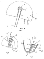
- the annular wheel rim has been indicated with the reference numeral 1. Only a small circle segment of the rim 1 has been shown.
- the rim 1 here comprises two opposite radially outwardly extending annular sidewall parts 2a, 2b, a radial inward bottom wall part 3 and a radial outward tyre support wall part 4.
- the wall parts 2, 3, 4, seen in cross section, form a circumferentially closed wall inside which an internal hollow space 5 is present.
- the internal hollow space 5 runs like an annulus around a central axis of rotation 7.
- the rim 1 is connected to a central hub 8 by means of a plurality of spokes 10 of which only two are shown.
- Each spoke 10 comprises a longitudinal shaft 11 with an integral head 12 at its radial outward end (see fig. 3 ).
- the head 12 has a larger cross section than the shaft 11.
- the head 12 has a width/thickness (cross sectional dimension) which is at least one and a half times larger than the width/thickness (cross sectional dimension) of the shaft 11.
- each slit extends both in a transverse sideward direction X and in a radial outward direction Y. Furthermore each slit comprises a first slit part 15 and a second slit part 16. The first slit part 15 starts near the centre of the bottom wall part 3 and from there runs sideward and outward in the directions X and Y.
- the second slit part 16 extends above the entire radial outward side of the first slit part 15.
- the first slit part 15 is open in the directions - Y towards the central axis of rotation 7 and +X towards the sidewall part 2a in which it is provided.
- the second slit part 16 is open in the direction -Y towards the first slit part 15 below it and +X towards the sidewall part 2a in which it is provided.
- the first slit part 15 has cross sectional dimensions slightly larger than the shaft 11 and substantially smaller than the head 12.
- the second slit part 16 has cross sectional dimensions slightly larger than the head 12.
- the two slit parts 15, 16 delimit a T-shape which is substantially complementary to the upper part of the spoke 10.
- the slit parts 15, 16 of each slit are delimited by so-called standing strengthening wall parts 20', 20" extending in the radial direction Y and so-called lying strengthening wall parts 21', 21" extending in the sideward direction X. Together these standing and lying strengthening wall parts 20, 21 form a closed pocket around the slit which pocket extends inwardly into the internal annular space 5 of the rim 1.
- the strengthening wall parts 20, 21 are manufactured integral with the rest of the rim wall.
- the lying strengthening wall parts 21' extending between the transition of the first and second slit part 15, 16 form a seat 23 for the head 12 of the spoke 10 to abut against while the spoke shaft 11 extends through the first slit part 15 in the direction of the central axis 7.
- the closed pockets have the large advantage that the rim wall can maintain continuous even at the location of the spoke mounting apertures. The drilling of holes in the rim wall is not necessary for making the slits.
- each spoke 10 may simply be pushed with its head 12 and upper shaft part 11 into one of the two-part slits, until they reach their seated end position in there.
- the spokes 10 are then connected with their free ends with the hub 8 and brought to a desired tension.
- the hub 8 may be provided with nipple openings 25 in opposite flanges 8', 8" of the hub 8, into which openings 25 threaded nipples are placed.
- the spokes 10 do not have to be bend or otherwise deformed to be able to connect them with the rim 1 and hub 8.
- the spokes 10 can advantageously be made fully straight with one common longitudinal axis.
- the rim and the slit shaped apertures therein may be given other shapes and dimensions. It is also possible to provide the hub directly with threaded holes into which spoke ends can be screwed or to connect the spokes with hooked and/or thickened end parts with the hub. The head of the spoke may even be formed by a nipple. This makes it possible to use the rim according to the invention in combination with all kinds of hubs and with or without 'reversed' spokes.
- the rim can be made out of various kinds of materials, for example metal. Preferably, however the rim is made out of a moulded composite material, in particular a carbon fibre reinforced material.
- the construction with the closed pockets makes the rim very suitable to be made out of such a moulded composite material.
- the slit parts shown extend in a sideward direction substantially perpendicular to the sidewall parts. In the alternative it is also possible to have them extend under an oblique angle to these sidewall parts.
- a bicycle wheel rim which aids in making a bicycle lightweight, strong and fast during accelerations. In particular during racing where the demands are high, this may make a critical positive difference.
Landscapes
- Engineering & Computer Science (AREA)
- Mechanical Engineering (AREA)
- Chemical & Material Sciences (AREA)
- Materials Engineering (AREA)
- Tires In General (AREA)
Claims (10)
- Jante (1) pour vélo ayant un axe de rotation central (7), comprenant :une paroi avec deux parties de paroi latérale annulaires s'étendant radialement vers l'extérieur (2a, 2b) ;une pluralité d'ouvertures de montage de rayon dans la paroi ;une pluralité de rayons (10) destinés à raccorder la jante (1) avec un moyeu central (8) ;dans laquelle les rayons (10) comprennent une tige (11) avec une tête (12) au niveau de son extrémité radialement externe, laquelle tête (12) a une section transversale plus importante que la tige (11) ;dans laquelle les parties de paroi de la jante (1) qui délimitent les ouvertures de montage de rayon, forment des sièges pour les têtes (12) des rayons (10) afin de venir en butée contre ces derniers, alors que les tiges de rayon (11) s'étendent à travers les ouvertures dans la direction dudit axe central (7),au moins l'une des ouvertures de montage de rayon est formée par une fente,ladite fente s'étend à la fois dans une direction latérale et radialement externe (X resp. Y) et comprend une première partie de fente (15) et une seconde partie de fente (16) dans laquelle la première partie de fente (15) a des dimensions transversales entre les dimensions transversales de la tige (11) et de la tête (12), et la seconde partie de fente (16) a des dimensions transversales supérieures aux dimensions transversales de la tête (12),dans laquelle la seconde partie de fente (16) se trouve plus radialement vers l'extérieur que la première partie de fente (15), et dans laquelle les parties de fente (15, 16) sont toutes deux ouvertes dans la direction de l'axe central (7) de la jante (1) dans la direction d'au moins l'une des parties de paroi latérale (2a, 2b) de la jante (1),caractérisée en ce que :lesdites parties de paroi de la jante (1) sont prévues avec des parties de paroi de renforcement (20, 21) qui délimitent les parties de fente (15, 16) vers un espace annulaire interne (5) de la jante (1).
- Jante pour vélo selon la revendication 1, dans laquelle les parties de paroi de renforcement (20, 21) qui délimitent les parties de fente (15, 16) vers l'espace annulaire interne (5), forment une poche fermée dans la paroi de jante.
- Jante pour vélo selon la revendication 1 ou 2, dans laquelle les parties de paroi de renforcement (20, 21), qui délimitent les parties de fente (15, 16) vers l'espace annulaire interne (5) sont fabriquées de manière solidaire avec la paroi de jante.
- Jante pour vélo selon l'une des revendications précédentes, dans laquelle les parties de paroi de renforcement (20, 21) qui délimitent les parties de fente (15, 16), comprennent des parties de paroi de renforcement droites (20', 20") s'étendant dans la direction radiale (Y) et se trouvant sur les parties de paroi de renforcement (21', 21") s'étendant dans la direction latérale (X).
- Jante pour vélo selon l'une des revendications précédentes, dans laquelle la seconde partie de fente (16) s'étend complètement dans la direction latérale (X) et a des parties de paroi (21') délimitant son côté radialement interne formant le siège (23) pour la tête (12) du rayon (10) afin de venir en butée contre ce dernier, alors que la tige de rayon (11) s'étend à travers la première partie de fente (15) dans la direction dudit axe central (7).
- Jante pour vélo selon l'une des revendications précédentes, dans laquelle la fente qui est ouverte dans la direction d'au moins l'une des parties de paroi latérale (2a, 2b) de la jante (1), est ouverte dans une direction latérale perpendiculaire aux parties de paroi latérale (2a, 2b).
- Jante pour vélo selon l'une des revendications précédentes, dans laquelle des ouvertures de montage de rayon adjacentes ayant leurs fentes ouvertes vers les directions latérales opposées.
- Jante pour vélo selon l'une des revendications précédentes, dans laquelle la jante (1) est réalisée avec un matériau composite moulé, en particulier un matériau renforcé en fibres de carbone.
- Roue de vélo comprenant :un moyeu central (8) ayant des brides (8', 8") avec une pluralité d'ouvertures de montage de rayon (25) à l'intérieur de ces dernières ;une jante (1) pour vélo selon l'une des revendications précédentes, ayant ses rayons (10) qui raccordent le moyeu (8) et la jante (1) l'un à l'autre ; etune pluralité d'écrous de rayon pour fournir l'ajustement de tension des rayons (10).
- Vélo comprenant au moins une jante (1) pour vélo selon l'une des revendications précédentes.
Applications Claiming Priority (2)
| Application Number | Priority Date | Filing Date | Title |
|---|---|---|---|
| NL2004125A NL2004125C2 (en) | 2010-01-21 | 2010-01-21 | A bicycle wheel rim having sidewardly opening two-part slit shaped spoke mounting apertures. |
| PCT/EP2010/069410 WO2011088932A1 (fr) | 2010-01-21 | 2010-12-10 | Jante de roue de vélo présentant des ouvertures de montage des rayons en forme de fente en deux parties à ouverture latérale |
Publications (2)
| Publication Number | Publication Date |
|---|---|
| EP2525986A1 EP2525986A1 (fr) | 2012-11-28 |
| EP2525986B1 true EP2525986B1 (fr) | 2013-08-07 |
Family
ID=42333402
Family Applications (1)
| Application Number | Title | Priority Date | Filing Date |
|---|---|---|---|
| EP10795296.2A Not-in-force EP2525986B1 (fr) | 2010-01-21 | 2010-12-10 | Jante pour velo avec des ouvertures laterales en forme d'une fente en deux parties pour l'installation des rayons |
Country Status (6)
| Country | Link |
|---|---|
| US (1) | US20130062927A1 (fr) |
| EP (1) | EP2525986B1 (fr) |
| CN (1) | CN102821977A (fr) |
| NL (1) | NL2004125C2 (fr) |
| TW (1) | TW201139165A (fr) |
| WO (1) | WO2011088932A1 (fr) |
Families Citing this family (6)
| Publication number | Priority date | Publication date | Assignee | Title |
|---|---|---|---|---|
| DE102011081069A1 (de) * | 2011-08-17 | 2013-02-21 | Bayerische Motoren Werke Aktiengesellschaft | Speichenrad für schlauchlose Reifen |
| TWM427288U (en) * | 2011-12-23 | 2012-04-21 | Great Go Cycle Inc | Wheel rim structure with easy detachable spokes |
| TW201418061A (zh) * | 2012-11-07 | 2014-05-16 | Gigantex Composite Technologies Co Ltd | 輪圈與輪輻之組合 |
| DE102014200542A1 (de) * | 2014-01-14 | 2015-07-16 | Iam Components Gmbh | Speichenradfelge |
| TWI579158B (zh) * | 2015-02-09 | 2017-04-21 | Fang-Yi Li | Wheel structure |
| US10752047B2 (en) | 2016-08-23 | 2020-08-25 | Harley-Davidson Motor Company Group, LLC | Laced wheel and method of manufacture |
Family Cites Families (26)
| Publication number | Priority date | Publication date | Assignee | Title |
|---|---|---|---|---|
| US1222094A (en) * | 1913-03-03 | 1917-04-10 | Olive Frommann | Metallic-spoked wheel. |
| US1474405A (en) * | 1920-03-26 | 1923-11-20 | Charles E Wisner | Wire-spoked wheel |
| US1375435A (en) * | 1920-07-29 | 1921-04-19 | Firestone Steel Products Co | Demountable rim |
| US2937905A (en) * | 1955-11-29 | 1960-05-24 | Altenburger Karl | Spoke connection for tubeless tire rim |
| FR2526374A1 (fr) * | 1982-05-10 | 1983-11-10 | Michelin & Cie | Roue pour engin de moto-cross |
| US4978176A (en) * | 1989-06-22 | 1990-12-18 | Smith Bruce N | Spoked wheel |
| US5499864A (en) * | 1993-06-16 | 1996-03-19 | Klein Bicycle Corporation | Bicycle wheel rims |
| US5810453A (en) * | 1994-08-09 | 1998-09-22 | O'brien; Colin | Bicycle wheels having hub tightened spoke system |
| FR2727356A1 (fr) * | 1994-11-30 | 1996-05-31 | Mavic Sa | Jante de velo et roue comprenant une telle jante |
| DE4444044C2 (de) * | 1994-12-10 | 2001-11-08 | Josef Hasberg | Felgenrad für Fahrräder u. dgl. |
| US6158819A (en) * | 1997-11-13 | 2000-12-12 | Shimano Inc. | Bicycle wheel |
| IT245313Y1 (it) * | 1998-06-05 | 2002-03-20 | Aprilia World Service B V | Ruota a raggi perfezionata |
| US6234580B1 (en) * | 1999-07-13 | 2001-05-22 | Shimano Inc. | Bicycle wheel with reinforced rim |
| DE10000399C1 (de) * | 2000-01-07 | 2001-09-27 | Gubesch Gmbh | Fahrrad-Laufrad |
| US6364423B1 (en) * | 2000-09-29 | 2002-04-02 | Alex Machine Industrial Co., Ltd. | Retaining device adapted to retain tensely spokes between a wheel rim and a hub of a bicycle wheel |
| US6536849B1 (en) * | 2000-11-20 | 2003-03-25 | Shimano Inc. | Bicycle wheel |
| TW516518U (en) * | 2002-05-10 | 2003-01-01 | Jaan Luen Industry Co Ltd | Improved wheel rim structure for bicycle without inner tire |
| FR2842140B1 (fr) * | 2002-07-15 | 2005-01-07 | Michelin Soc Tech | Ensemble monte tubeless pour cycle, jante et pneumatique tubeless |
| US6736462B1 (en) * | 2002-12-16 | 2004-05-18 | Shimano, Inc. | Bicycle rim |
| US6776460B1 (en) * | 2003-08-15 | 2004-08-17 | Chun-Hsun Lo | Combination of spokes and rims for bicycles |
| DE102004047264B4 (de) * | 2004-09-24 | 2007-01-04 | Friebel, Moritz, Dr. | Speichenlaufrad mit gewichtsminimierter und aerodynamisch optimierter Hohlkammerfelge |
| DE102004055892B4 (de) * | 2004-11-19 | 2010-12-09 | Ktm-Sportmotorcycle Ag | Speichenradfelge für Schlauchlosreifen |
| US20060273654A1 (en) * | 2005-06-03 | 2006-12-07 | Tung-Kuei Lien | Bicycle wheel rim |
| FR2887493B1 (fr) * | 2005-06-23 | 2007-09-21 | Salomon Sa | Jante pour une roue a rayons en traction et roue comprenant une telle jante |
| US20070188011A1 (en) * | 2006-02-13 | 2007-08-16 | Kinlin Industrial Corporation | Bicycle rim assembly with multiple easily-assembled spokes |
| FR2912345B1 (fr) * | 2007-02-09 | 2009-05-08 | Salomon Sa | Rayon en matiere composite pour une roue a rayons. |
-
2010
- 2010-01-21 NL NL2004125A patent/NL2004125C2/en not_active IP Right Cessation
- 2010-12-10 EP EP10795296.2A patent/EP2525986B1/fr not_active Not-in-force
- 2010-12-10 WO PCT/EP2010/069410 patent/WO2011088932A1/fr not_active Ceased
- 2010-12-10 US US13/520,826 patent/US20130062927A1/en not_active Abandoned
- 2010-12-10 CN CN2010800621219A patent/CN102821977A/zh active Pending
- 2010-12-29 TW TW099146653A patent/TW201139165A/zh unknown
Also Published As
| Publication number | Publication date |
|---|---|
| EP2525986A1 (fr) | 2012-11-28 |
| WO2011088932A1 (fr) | 2011-07-28 |
| US20130062927A1 (en) | 2013-03-14 |
| CN102821977A (zh) | 2012-12-12 |
| TW201139165A (en) | 2011-11-16 |
| NL2004125C2 (en) | 2011-07-25 |
Similar Documents
| Publication | Publication Date | Title |
|---|---|---|
| EP2525986B1 (fr) | Jante pour velo avec des ouvertures laterales en forme d'une fente en deux parties pour l'installation des rayons | |
| US6196638B1 (en) | Bicycle wheel | |
| US6367883B1 (en) | Bicycle wheel | |
| TWI604969B (zh) | 自行車輪轂及自行車輪 | |
| US7967392B2 (en) | Hub body for a bicycle wheel and hub comprising such a hub body | |
| EP3505365B1 (fr) | Jante de bicyclette | |
| EP1923232A1 (fr) | Moyeu pour une roue de bicyclette et roue de bicyclette comprenant un tel moyeu | |
| US9676232B2 (en) | Wheel hub with centering device | |
| KR20190032612A (ko) | 차량 휠 디스크, 휠 디스크를 포함하는 차량 휠 및 휠 디스크와 차량 휠을 제조하는 방법 | |
| EP2492112B1 (fr) | Structure de fixation de rayon | |
| US7651172B2 (en) | Hub body of a spoked bicycle wheel | |
| EP3397506B1 (fr) | Roue de véhicule fabriquée, disque de roue destiné à être utilisé dans une telle roue de véhicule fabriquée et procédé de production d'un tel disque de roue et d'une telle roue de véhicule fabriquée | |
| US6213562B1 (en) | Bicycle wheel with reinforced rim | |
| EP1491361A2 (fr) | Roue de bicyclette | |
| US8449044B2 (en) | Bicycle rim | |
| CN102649386B (zh) | 自行车轮圈 | |
| EP2403721B1 (fr) | Roue a rayons, en particulier pour un pneu de type sans chambre a air, destinee a etre montee sur un vehicule, en particulier sur un vehicule motorise ou une motocyclette | |
| EP1262334B1 (fr) | Roue de bicyclette | |
| EP4284657B1 (fr) | Ensemble moyeu de cycle | |
| JP7466285B2 (ja) | 車輪 |
Legal Events
| Date | Code | Title | Description |
|---|---|---|---|
| PUAI | Public reference made under article 153(3) epc to a published international application that has entered the european phase |
Free format text: ORIGINAL CODE: 0009012 |
|
| 17P | Request for examination filed |
Effective date: 20120622 |
|
| AK | Designated contracting states |
Kind code of ref document: A1 Designated state(s): AL AT BE BG CH CY CZ DE DK EE ES FI FR GB GR HR HU IE IS IT LI LT LU LV MC MK MT NL NO PL PT RO RS SE SI SK SM TR |
|
| DAX | Request for extension of the european patent (deleted) | ||
| GRAP | Despatch of communication of intention to grant a patent |
Free format text: ORIGINAL CODE: EPIDOSNIGR1 |
|
| INTG | Intention to grant announced |
Effective date: 20130506 |
|
| GRAS | Grant fee paid |
Free format text: ORIGINAL CODE: EPIDOSNIGR3 |
|
| GRAA | (expected) grant |
Free format text: ORIGINAL CODE: 0009210 |
|
| AK | Designated contracting states |
Kind code of ref document: B1 Designated state(s): AL AT BE BG CH CY CZ DE DK EE ES FI FR GB GR HR HU IE IS IT LI LT LU LV MC MK MT NL NO PL PT RO RS SE SI SK SM TR |
|
| REG | Reference to a national code |
Ref country code: GB Ref legal event code: FG4D |
|
| REG | Reference to a national code |
Ref country code: AT Ref legal event code: REF Ref document number: 625581 Country of ref document: AT Kind code of ref document: T Effective date: 20130815 Ref country code: CH Ref legal event code: EP |
|
| REG | Reference to a national code |
Ref country code: IE Ref legal event code: FG4D |
|
| REG | Reference to a national code |
Ref country code: DE Ref legal event code: R096 Ref document number: 602010009282 Country of ref document: DE Effective date: 20130926 |
|
| REG | Reference to a national code |
Ref country code: AT Ref legal event code: MK05 Ref document number: 625581 Country of ref document: AT Kind code of ref document: T Effective date: 20130807 |
|
| REG | Reference to a national code |
Ref country code: NL Ref legal event code: T3 |
|
| REG | Reference to a national code |
Ref country code: LT Ref legal event code: MG4D |
|
| PG25 | Lapsed in a contracting state [announced via postgrant information from national office to epo] |
Ref country code: IS Free format text: LAPSE BECAUSE OF FAILURE TO SUBMIT A TRANSLATION OF THE DESCRIPTION OR TO PAY THE FEE WITHIN THE PRESCRIBED TIME-LIMIT Effective date: 20131207 Ref country code: CY Free format text: LAPSE BECAUSE OF FAILURE TO SUBMIT A TRANSLATION OF THE DESCRIPTION OR TO PAY THE FEE WITHIN THE PRESCRIBED TIME-LIMIT Effective date: 20130918 Ref country code: LT Free format text: LAPSE BECAUSE OF FAILURE TO SUBMIT A TRANSLATION OF THE DESCRIPTION OR TO PAY THE FEE WITHIN THE PRESCRIBED TIME-LIMIT Effective date: 20130807 Ref country code: AT Free format text: LAPSE BECAUSE OF FAILURE TO SUBMIT A TRANSLATION OF THE DESCRIPTION OR TO PAY THE FEE WITHIN THE PRESCRIBED TIME-LIMIT Effective date: 20130807 Ref country code: SE Free format text: LAPSE BECAUSE OF FAILURE TO SUBMIT A TRANSLATION OF THE DESCRIPTION OR TO PAY THE FEE WITHIN THE PRESCRIBED TIME-LIMIT Effective date: 20130807 Ref country code: HR Free format text: LAPSE BECAUSE OF FAILURE TO SUBMIT A TRANSLATION OF THE DESCRIPTION OR TO PAY THE FEE WITHIN THE PRESCRIBED TIME-LIMIT Effective date: 20130807 Ref country code: PT Free format text: LAPSE BECAUSE OF FAILURE TO SUBMIT A TRANSLATION OF THE DESCRIPTION OR TO PAY THE FEE WITHIN THE PRESCRIBED TIME-LIMIT Effective date: 20131209 Ref country code: NO Free format text: LAPSE BECAUSE OF FAILURE TO SUBMIT A TRANSLATION OF THE DESCRIPTION OR TO PAY THE FEE WITHIN THE PRESCRIBED TIME-LIMIT Effective date: 20131107 |
|
| PG25 | Lapsed in a contracting state [announced via postgrant information from national office to epo] |
Ref country code: BE Free format text: LAPSE BECAUSE OF FAILURE TO SUBMIT A TRANSLATION OF THE DESCRIPTION OR TO PAY THE FEE WITHIN THE PRESCRIBED TIME-LIMIT Effective date: 20130807 Ref country code: FI Free format text: LAPSE BECAUSE OF FAILURE TO SUBMIT A TRANSLATION OF THE DESCRIPTION OR TO PAY THE FEE WITHIN THE PRESCRIBED TIME-LIMIT Effective date: 20130807 Ref country code: PL Free format text: LAPSE BECAUSE OF FAILURE TO SUBMIT A TRANSLATION OF THE DESCRIPTION OR TO PAY THE FEE WITHIN THE PRESCRIBED TIME-LIMIT Effective date: 20130807 Ref country code: GR Free format text: LAPSE BECAUSE OF FAILURE TO SUBMIT A TRANSLATION OF THE DESCRIPTION OR TO PAY THE FEE WITHIN THE PRESCRIBED TIME-LIMIT Effective date: 20131108 Ref country code: LV Free format text: LAPSE BECAUSE OF FAILURE TO SUBMIT A TRANSLATION OF THE DESCRIPTION OR TO PAY THE FEE WITHIN THE PRESCRIBED TIME-LIMIT Effective date: 20130807 |
|
| PGFP | Annual fee paid to national office [announced via postgrant information from national office to epo] |
Ref country code: IT Payment date: 20131231 Year of fee payment: 4 |
|
| PG25 | Lapsed in a contracting state [announced via postgrant information from national office to epo] |
Ref country code: CY Free format text: LAPSE BECAUSE OF FAILURE TO SUBMIT A TRANSLATION OF THE DESCRIPTION OR TO PAY THE FEE WITHIN THE PRESCRIBED TIME-LIMIT Effective date: 20130807 |
|
| PG25 | Lapsed in a contracting state [announced via postgrant information from national office to epo] |
Ref country code: CZ Free format text: LAPSE BECAUSE OF FAILURE TO SUBMIT A TRANSLATION OF THE DESCRIPTION OR TO PAY THE FEE WITHIN THE PRESCRIBED TIME-LIMIT Effective date: 20130807 Ref country code: RO Free format text: LAPSE BECAUSE OF FAILURE TO SUBMIT A TRANSLATION OF THE DESCRIPTION OR TO PAY THE FEE WITHIN THE PRESCRIBED TIME-LIMIT Effective date: 20130807 Ref country code: DK Free format text: LAPSE BECAUSE OF FAILURE TO SUBMIT A TRANSLATION OF THE DESCRIPTION OR TO PAY THE FEE WITHIN THE PRESCRIBED TIME-LIMIT Effective date: 20130807 Ref country code: EE Free format text: LAPSE BECAUSE OF FAILURE TO SUBMIT A TRANSLATION OF THE DESCRIPTION OR TO PAY THE FEE WITHIN THE PRESCRIBED TIME-LIMIT Effective date: 20130807 Ref country code: SK Free format text: LAPSE BECAUSE OF FAILURE TO SUBMIT A TRANSLATION OF THE DESCRIPTION OR TO PAY THE FEE WITHIN THE PRESCRIBED TIME-LIMIT Effective date: 20130807 |
|
| PGFP | Annual fee paid to national office [announced via postgrant information from national office to epo] |
Ref country code: NL Payment date: 20140328 Year of fee payment: 4 |
|
| PG25 | Lapsed in a contracting state [announced via postgrant information from national office to epo] |
Ref country code: ES Free format text: LAPSE BECAUSE OF FAILURE TO SUBMIT A TRANSLATION OF THE DESCRIPTION OR TO PAY THE FEE WITHIN THE PRESCRIBED TIME-LIMIT Effective date: 20130807 |
|
| PLBE | No opposition filed within time limit |
Free format text: ORIGINAL CODE: 0009261 |
|
| STAA | Information on the status of an ep patent application or granted ep patent |
Free format text: STATUS: NO OPPOSITION FILED WITHIN TIME LIMIT |
|
| 26N | No opposition filed |
Effective date: 20140508 |
|
| REG | Reference to a national code |
Ref country code: DE Ref legal event code: R097 Ref document number: 602010009282 Country of ref document: DE Effective date: 20140508 |
|
| PG25 | Lapsed in a contracting state [announced via postgrant information from national office to epo] |
Ref country code: LU Free format text: LAPSE BECAUSE OF FAILURE TO SUBMIT A TRANSLATION OF THE DESCRIPTION OR TO PAY THE FEE WITHIN THE PRESCRIBED TIME-LIMIT Effective date: 20131210 |
|
| PGFP | Annual fee paid to national office [announced via postgrant information from national office to epo] |
Ref country code: DE Payment date: 20140325 Year of fee payment: 4 Ref country code: FR Payment date: 20140326 Year of fee payment: 4 |
|
| REG | Reference to a national code |
Ref country code: IE Ref legal event code: MM4A |
|
| PG25 | Lapsed in a contracting state [announced via postgrant information from national office to epo] |
Ref country code: IE Free format text: LAPSE BECAUSE OF NON-PAYMENT OF DUE FEES Effective date: 20131210 |
|
| PG25 | Lapsed in a contracting state [announced via postgrant information from national office to epo] |
Ref country code: MC Free format text: LAPSE BECAUSE OF FAILURE TO SUBMIT A TRANSLATION OF THE DESCRIPTION OR TO PAY THE FEE WITHIN THE PRESCRIBED TIME-LIMIT Effective date: 20130807 |
|
| PG25 | Lapsed in a contracting state [announced via postgrant information from national office to epo] |
Ref country code: SM Free format text: LAPSE BECAUSE OF FAILURE TO SUBMIT A TRANSLATION OF THE DESCRIPTION OR TO PAY THE FEE WITHIN THE PRESCRIBED TIME-LIMIT Effective date: 20130807 |
|
| REG | Reference to a national code |
Ref country code: DE Ref legal event code: R119 Ref document number: 602010009282 Country of ref document: DE |
|
| REG | Reference to a national code |
Ref country code: NL Ref legal event code: V1 Effective date: 20150701 |
|
| REG | Reference to a national code |
Ref country code: NL Ref legal event code: V1 Effective date: 20150701 |
|
| PG25 | Lapsed in a contracting state [announced via postgrant information from national office to epo] |
Ref country code: HU Free format text: LAPSE BECAUSE OF FAILURE TO SUBMIT A TRANSLATION OF THE DESCRIPTION OR TO PAY THE FEE WITHIN THE PRESCRIBED TIME-LIMIT; INVALID AB INITIO Effective date: 20101210 Ref country code: MK Free format text: LAPSE BECAUSE OF FAILURE TO SUBMIT A TRANSLATION OF THE DESCRIPTION OR TO PAY THE FEE WITHIN THE PRESCRIBED TIME-LIMIT Effective date: 20130807 Ref country code: SI Free format text: LAPSE BECAUSE OF NON-PAYMENT OF DUE FEES Effective date: 20140110 Ref country code: BG Free format text: LAPSE BECAUSE OF FAILURE TO SUBMIT A TRANSLATION OF THE DESCRIPTION OR TO PAY THE FEE WITHIN THE PRESCRIBED TIME-LIMIT Effective date: 20130807 Ref country code: RS Free format text: LAPSE BECAUSE OF FAILURE TO SUBMIT A TRANSLATION OF THE DESCRIPTION OR TO PAY THE FEE WITHIN THE PRESCRIBED TIME-LIMIT Effective date: 20131107 |
|
| REG | Reference to a national code |
Ref country code: CH Ref legal event code: PL |
|
| GBPC | Gb: european patent ceased through non-payment of renewal fee |
Effective date: 20141210 |
|
| PG25 | Lapsed in a contracting state [announced via postgrant information from national office to epo] |
Ref country code: MT Free format text: LAPSE BECAUSE OF FAILURE TO SUBMIT A TRANSLATION OF THE DESCRIPTION OR TO PAY THE FEE WITHIN THE PRESCRIBED TIME-LIMIT Effective date: 20130807 |
|
| REG | Reference to a national code |
Ref country code: FR Ref legal event code: ST Effective date: 20150831 |
|
| PG25 | Lapsed in a contracting state [announced via postgrant information from national office to epo] |
Ref country code: NL Free format text: LAPSE BECAUSE OF NON-PAYMENT OF DUE FEES Effective date: 20150701 |
|
| PG25 | Lapsed in a contracting state [announced via postgrant information from national office to epo] |
Ref country code: CH Free format text: LAPSE BECAUSE OF NON-PAYMENT OF DUE FEES Effective date: 20141231 Ref country code: LI Free format text: LAPSE BECAUSE OF NON-PAYMENT OF DUE FEES Effective date: 20141231 Ref country code: GB Free format text: LAPSE BECAUSE OF NON-PAYMENT OF DUE FEES Effective date: 20141210 Ref country code: DE Free format text: LAPSE BECAUSE OF NON-PAYMENT OF DUE FEES Effective date: 20150701 |
|
| PG25 | Lapsed in a contracting state [announced via postgrant information from national office to epo] |
Ref country code: FR Free format text: LAPSE BECAUSE OF NON-PAYMENT OF DUE FEES Effective date: 20141231 |
|
| PG25 | Lapsed in a contracting state [announced via postgrant information from national office to epo] |
Ref country code: IT Free format text: LAPSE BECAUSE OF NON-PAYMENT OF DUE FEES Effective date: 20141210 |
|
| PG25 | Lapsed in a contracting state [announced via postgrant information from national office to epo] |
Ref country code: TR Free format text: LAPSE BECAUSE OF FAILURE TO SUBMIT A TRANSLATION OF THE DESCRIPTION OR TO PAY THE FEE WITHIN THE PRESCRIBED TIME-LIMIT Effective date: 20130807 |
|
| PG25 | Lapsed in a contracting state [announced via postgrant information from national office to epo] |
Ref country code: AL Free format text: LAPSE BECAUSE OF FAILURE TO SUBMIT A TRANSLATION OF THE DESCRIPTION OR TO PAY THE FEE WITHIN THE PRESCRIBED TIME-LIMIT Effective date: 20130807 |