EP1491361A2 - Roue de bicyclette - Google Patents
Roue de bicyclette Download PDFInfo
- Publication number
- EP1491361A2 EP1491361A2 EP20040253721 EP04253721A EP1491361A2 EP 1491361 A2 EP1491361 A2 EP 1491361A2 EP 20040253721 EP20040253721 EP 20040253721 EP 04253721 A EP04253721 A EP 04253721A EP 1491361 A2 EP1491361 A2 EP 1491361A2
- Authority
- EP
- European Patent Office
- Prior art keywords
- hub
- spoke
- spokes
- rim
- nipple
- Prior art date
- Legal status (The legal status is an assumption and is not a legal conclusion. Google has not performed a legal analysis and makes no representation as to the accuracy of the status listed.)
- Withdrawn
Links
Images


Classifications
-
- B—PERFORMING OPERATIONS; TRANSPORTING
- B60—VEHICLES IN GENERAL
- B60B—VEHICLE WHEELS; CASTORS; AXLES FOR WHEELS OR CASTORS; INCREASING WHEEL ADHESION
- B60B21/00—Rims
- B60B21/02—Rims characterised by transverse section
- B60B21/025—Rims characterised by transverse section the transverse section being hollow
-
- B—PERFORMING OPERATIONS; TRANSPORTING
- B60—VEHICLES IN GENERAL
- B60B—VEHICLE WHEELS; CASTORS; AXLES FOR WHEELS OR CASTORS; INCREASING WHEEL ADHESION
- B60B1/00—Spoked wheels; Spokes thereof
- B60B1/02—Wheels with wire or other tension spokes
- B60B1/04—Attaching spokes to rim or hub
- B60B1/041—Attaching spokes to rim or hub of bicycle wheels
-
- B—PERFORMING OPERATIONS; TRANSPORTING
- B60—VEHICLES IN GENERAL
- B60B—VEHICLE WHEELS; CASTORS; AXLES FOR WHEELS OR CASTORS; INCREASING WHEEL ADHESION
- B60B1/00—Spoked wheels; Spokes thereof
- B60B1/02—Wheels with wire or other tension spokes
- B60B1/04—Attaching spokes to rim or hub
- B60B1/042—Attaching spokes to hub
-
- B—PERFORMING OPERATIONS; TRANSPORTING
- B60—VEHICLES IN GENERAL
- B60B—VEHICLE WHEELS; CASTORS; AXLES FOR WHEELS OR CASTORS; INCREASING WHEEL ADHESION
- B60B1/00—Spoked wheels; Spokes thereof
- B60B1/02—Wheels with wire or other tension spokes
- B60B1/04—Attaching spokes to rim or hub
- B60B1/043—Attaching spokes to rim
- B60B1/044—Attaching spokes to rim by the use of spoke nipples
Definitions
- This invention relates to bicycle wheels, and particularly wheels of the type having a rim and a hub connected by spokes.
- tension is applied thereto between the hub and the rim by means of a threaded connection between at least one end of each spoke and a nipple fitted to either the hub or the rim.
- spokes under tension integrally couple a rim and a hub.
- the outer end of each spoke is threadedly fitted in a nipple disposed in the rim, the inner end having its extreme end bent into a J-shape and inserted into spoke insert holes in a collar portion of the hub (hereinafter referred to as "hub collar").
- a large diameter portion at the extreme inner end engages with and is stopped at the collar portion.
- the portion bent into the J-shape of the spokes suffers from fatigue, thus shortening the service life of the spokes.
- the fact that the hub collar surface is not formed in parallel with the elevation angle formed by the spokes stretched between the rim and the hub also shortens the service life of the spokes because an unbalanced load is applied to the J-shaped portion of the spokes.
- a spoke support shaft is inserted into a flange provided on a hub, and an insert hole for engaging one end of the spoke is provided in a large diameter portion of the spoke support shaft.
- the spoke insert hole is made to be larger than axial diameter of the spoke so that the spoke is tiltable freely at an angle within a fixed range.
- the other end of the spoke is threadedly engaged, in a linear state, with the nipple of the rim (see Japanese Laid-Open Specification No: 108701/1996.
- the spoke insert hole of the spoke support shaft is larger than the diameter of the spoke as described above and is slightly smaller in diameter than the large diameter portion of the spoke end. Durability is therefore, not sufficient due to the force applied to the spokes and the spokes tend to slip out.
- the rim in a conventional bicycle wheel has a width larger than the rim height.
- a rim having larger height has been developed to take account of air resistance.
- this rim has been used in an otherwise conventional rim in which the number of spoke holes is 32 or 36.
- the increased rim height increases the longitudinal rim strength in a centrifugal direction by about two times compared with the conventional rim.
- a bicycle wheel has high longitudinal rim strength, it can function with minimal or without vibration even if some of the spokes are loose. This means that even if the spoke tension is somewhat uneven, in theory wheels without vibration can be supplied. However, this is not always accomplished.
- a bicycle wheel comprises a hub and a rim connected by a plurality of spokes, with a rim nipple at the outer end of each spoke and fitted in the rim, the inner ends of the spokes being received in a hub collar having a hub collar surface disposed substantially parallel to the spokes, each inner end having an external screw thread engaging a complementary threaded hole in a hub nipple mounted in a hub hole extending substantially at a right angle to the respective spoke, the hub nipple having an outer peripheral surface matching the internal surface of the hub hole, and the hub collar being formed with spoke insert holes for the passage of the spokes to the hub nipples in the hub holes.
- the spokes can be stretched to an optimal level, and the number of spokes can also be selected to minimise play, and achieve high durability.
- the hub collar includes a peripheral restraint wall on either side of the spoke insert holes. It is also preferred that the outer end of each spoke has an external thread engaging a complementary internal thread in a rim nipple. The screw threads at the inner and outer ends of each spoke are normally of opposite senses.
- spoke insert holes and the respective threaded holes in the hub nipples are arranged in two axially spaced peripheral rows in the hub.
- the complementary threaded hole in each hub nipple can be axially displaced from its central cross-section.
- the rim of the bicycle wheel preferably has a rim height at least equal to the rim width.
- the rim height is normally not less than 20 mm.
- the number of spokes preferably comprises a multiple of 4, typically in the range 16 to 28.
- the hub collar surface is formed approximately in parallel with the elevation angle on the spokes stretched between the hub and the rim.
- the hub hole for inserting and mounting the spokes into the hub collar is approximately at a right angle to the respective spokes, and is open to the hub collar surface.
- the hub nipples are fitted into the hub holes, and the spokes are threadedly fastened to the hub nipples, thus stretching the spokes in a linear form between the hub and the rim.
- the spokes in the outer periphery of the hub collar for stretching the spokes are formed in two axially adjacent rows, the spokes can be arranged alternately (in a zigzag manner) so that the spokes are not in contact when they cross, thus enhancing the strength and saving some weight. Since the spokes can be stretched while enhancing the strength as described, the number of spokes can be reduced to 16 to 28 as compared with the conventional bicycle wheel, with a consequent weight saving.
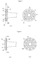
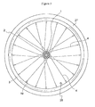
- the bicycle wheel of Figure 1 is formed with a hub collar 2 projected ringwise in a centrifugal direction on the outer circumference of both ends of a hub 1, and a spoke 4 is disposed and connected between the hub collar 2 and a rim 3.
- a hub collar surface 6 is formed on the hub 1 approximately parallel with an elevation angle 5 between the spoke 4 stretched between the hub collar 2 and the rim 3 and the plane of the rim.
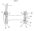
- a hub hole 9 is provided extending through approximately at a right angle to the spoke or the complement to the elevation angle 5 in order to receive a hub nipple 8 formed on a circular body 7.
- the outer peripheral surface 10 of the circular body 7 of the hub nipple 8 is formed to have approximately the same shape having a diameter matching that of an inner peripheral surface 11 of the hub hole 9.
- An outer peripheral surface 14 of the hub collar 2 is formed with a spoke insert hole 12 into which the spoke 4 is inserted, the spoke insert hole 12 being bored to the inner peripheral surface 11 of the hub hole 9.
- a peripheral restraint wall 13 having the spoke insert hole 12 interposed and opposite left and right thereof is stood upright ringwise on the outer peripheral surface 14 of the hub collar 2. The peripheral restraint wall 13 is provided to stabilise the engagement of the spoke 4 with the hub 1.
- the spokes 4 are formed with external threads 15 on both ends thereof, and the external thread 15 on one end of the spoke 4 is fastened to internal thread 16 provided on the circular body 7 of the hub nipple 8 inserted from the spoke insert hole 12 side and fitted into the hub hole 9. Further, in this embodiment a rim nipple 19 having matching internal threads 16 is mounted in a spoke hole 17 formed in the rim 3 from the outside of the rim 3. The external threads 15 on the other end of the spoke 4 are fastened to the internal thread 16 of the rim nipple 19 mounted into the rim 3. With the hub 1 and the rim 3 connected by the spokes 4, a tyre 27 may be fitted in the rim 3 of the wheel, as shown in Figure 5, the rim 3 having an additional opening for an air valve 28.
- connection of the rim 3 and the hub 1 by a plurality of spokes 4 creates spoke crossings in which intermediate portions thereof are crossed, similarly to the assembly of a normal bicycle.
- the spokes 4 used in wheels of the invention are normally formed with an external thread 15 on both ends.
- the threads 15 on one end typically extend to 4 to 7 mm from the end, which is sufficient to be threadedly fastened to the hub nipple 8.
- the external thread 15 on the other end thereof can be of the opposite sense, and extend 8 to 12 mm from the end, to be threadedly fastened to the rim nipple 19.
- These spokes 4 are threadedly fastened to the hub nipple 8 and the rim nipple 19, respectively, and stretched by applying tension between the hub 1 and the rim 3 to firmly connect the hub 1 and the rim 3.
- the hub collar 2 in a wheel of the invention may have a collar width 23 of a thickness of 5 to 8 mm.
- the hub collar surface 6 is formed in a surface approximately at the elevation angle 5, typically 2° to 10°.
- the inner peripheral surface 11 of the hub hole 9 formed approximately at a right angle to the hub collar surface 6 is formed to be circular having approximately the same diameter as that of the circular body 7 of the hub nipple 8.
- the spoke insert hole 12 bored in a direction of a wheel axis from the outer peripheral surface 14 of the hub collar 2 and reaching the inner peripheral surface 11 of the hub hole 9 is formed into a slit 20 between the peripheral restraint walls 13.
- the length of the circular body 7 of the hub nipple 8 can be the same as or somewhat shorter than or longer than the thickness of the collar width 23 of the hub collar 2.
- the spoke 4 preferably does not extend through the hub nipple 8.
- the hole 26 in the nipple 8 is itself closed.
- the spokes 4 are threadedly fastened to the spoke threaded hole 26 of the circular body 7 of the hub nipple 8, and the circular body 7 of the hub nipple 8 is fitted into the hub hole 9 opened to the hub collar surface 6 approximately at a right angle to the elevation angle 5 between the rim 3 and the hub collar 2.
- the spokes 4 are threadedly fastened to the spoke threaded hole 26 opened to the circular body 7 of the hub nipple 8 shaped to be rotatable in the direction of the plane angle 24.
- the spokes 4 are stretched while being applied with tension without being bent between the hub collar 2 and the rim 3.
- the threaded hole 26 of the hub nipple 8 fitted in the hub hole 9 can be central of the circular body 7 or be displaced to one or other end.
- the spokes 4 of the bicycle wheel according to the present invention are coupled in conventional manner to a conventional rim.
- the engagement with the hub 1 is carried out by the hub nipple 8 comprising the circular body 7, and the hub nipple 8, and the spokes 4 are threadedly fastened in the spoke threaded holes 26.
- the circular shape of the hub nipple 8, means that even if the spokes 4, being provided with the hub collar 2 and the plane angle 24 are crossed, they can be freely rotated laterally by the circular body 7, and therefore, even if the plane angle 24 is provided, the spokes 4 can be stretched between the hub 1 and the rim 3 while maintaining a linear form.
- the hub collar surface 6 is formed in parallel with the elevation angle 5 formed by the spokes 4, and the hub holes 9 for inserting and mounting the hub nipple 8 are approximately at a right angle to the respective spokes. Therefore, the spokes 4 threadedly engaged with the hub nipple 8 can be also stretched between the hub 1 and the rim 3 while maintaining a linear form.
- peripheral restraint walls 13 provided in the circumferential direction on the outer peripheral surface 14 of the hub collar 2 having the hub nipple 8 inserted and mounted therein, are of two rows on left and right, eight to fourteen spokes 4 are inserted and mounted in one row in the slit 20 between the two rows on left and right.
- the spokes 4 inserted and mounted in one row as described will cross and be in contact at the spoke intersections 25, and as a consequence are somewhat bent thereat.
- the spoke threaded hole 26 is located toward the end of the circular body 7, as shown in Figures 12(b) and (b').
- the hub nipple 8 is inverted so that they can be adapted to the respective positions.
- the length of the circular body 7 of the hub nipple 8 can be shortened, in which case, therefore, when the spoke threaded hole 26 is provided in the centre of the length of the circular body as shown in Figure 12 (a') so that the spokes 4 may pass through the left and right slits 20, the length of the circular body 7 is shortened so as to prevent them from flying out from the surface of the hub collar 2.
- the length of the circular body 7 of the hub nipple 8 is made longer than the width 23 of the collar 2 or the width of the slit 20.
- the spoke threaded hole 26 is provided in the centre of the circular body 7 as in Figure 12 (a'), and the hub nipple 8 is moved to and disposed at a position that the spokes 4 are to be alternate (a zigzag state).
- the hub nipple 8 in which the width of the circular body 7 is made longer than the width 23 of the collar 2 or the width of the slit 20 may be also used for the structure in which there are three peripheral restraint walls 13.
- the shape of the hub hole 9 provided in the hub collar 2 can be made, other than a circle, such that only the portion in the centrifugal direction is a circular and the wheel shaft side is a square.
- the shape of the hub nipple 8 can be also made, adjusting to the shape of the former, such that as shown in Figure 12 (c) and (d), the upper portion in the centrifugal direction from the circular body 7 is an arc.
- the side portion on the wheel shaft side is a notch portion 18 recessed in the form of an arc, which can be light-weighted by a portion of the recessed notch 18.
- the slit 20 formed in the outer peripheral surface 14 of the hub collar 2 can be formed around on the whole surface of the outer peripheral surface of the hub collar 2 as described above, it is noted the slit 20 is partly formed only in front and behind of the spoke insert hole 12 for inserting and mounting the spokes 4.
- the spokes 4 can be stretched without trouble by providing crossing with an angle of the elevation angle 24. By doing so, it is not necessary to provide the peripheral restraint walls 13 on the whole circumference, but local restraint walls 13a are partly formed only in the circumference of the spoke insert holes 12 to enable strengthening the hub 1 by that portion.
Landscapes
- Engineering & Computer Science (AREA)
- Mechanical Engineering (AREA)
- Tires In General (AREA)
- Molds, Cores, And Manufacturing Methods Thereof (AREA)
- Axle Suspensions And Sidecars For Cycles (AREA)
Applications Claiming Priority (2)
| Application Number | Priority Date | Filing Date | Title |
|---|---|---|---|
| JP2003181906A JP3878155B2 (ja) | 2003-06-25 | 2003-06-25 | スポークによりリムとハブを連結した自転車用車輪 |
| JP2003181906 | 2003-06-25 |
Publications (2)
| Publication Number | Publication Date |
|---|---|
| EP1491361A2 true EP1491361A2 (fr) | 2004-12-29 |
| EP1491361A3 EP1491361A3 (fr) | 2005-04-06 |
Family
ID=33411087
Family Applications (1)
| Application Number | Title | Priority Date | Filing Date |
|---|---|---|---|
| EP04253721A Withdrawn EP1491361A3 (fr) | 2003-06-25 | 2004-06-22 | Roue de bicyclette |
Country Status (5)
| Country | Link |
|---|---|
| US (1) | US7070245B2 (fr) |
| EP (1) | EP1491361A3 (fr) |
| JP (1) | JP3878155B2 (fr) |
| CN (1) | CN100369760C (fr) |
| TW (1) | TWI242502B (fr) |
Cited By (4)
| Publication number | Priority date | Publication date | Assignee | Title |
|---|---|---|---|---|
| EP1923231A1 (fr) * | 2006-11-20 | 2008-05-21 | CAMPAGNOLO S.r.l. | Roue, rayon et moyeu de bicyclette pour une telle roue et procédé d'assemblage de la roue |
| EP1726457A3 (fr) * | 2005-05-27 | 2009-12-02 | Shimano Inc. | Moyeu de bicyclette |
| US9815322B2 (en) | 2015-01-19 | 2017-11-14 | Shimano Inc. | Bicycle hub and bicycle wheel assembly |
| CN113085438A (zh) * | 2021-05-12 | 2021-07-09 | 台铃科技发展有限公司 | 电动车前轮 |
Families Citing this family (9)
| Publication number | Priority date | Publication date | Assignee | Title |
|---|---|---|---|---|
| US20060145530A1 (en) * | 2004-05-28 | 2006-07-06 | Rinard Damon | Flangeless and straight spoked bicycle wheel set |
| US7360847B2 (en) * | 2005-05-27 | 2008-04-22 | Shimano Inc. | Bicycle hub |
| US7562940B2 (en) | 2005-12-22 | 2009-07-21 | Specialized Bicycle Components, Inc. | Bicycle wheel and hub |
| US7562942B2 (en) * | 2005-12-22 | 2009-07-21 | Specialized Bicycle Components, Inc. | Bicycle wheel and release mechanism |
| US7726746B2 (en) * | 2007-08-28 | 2010-06-01 | Berens Martin C | Hubcap having lighted spinning element |
| US7631945B2 (en) * | 2007-08-28 | 2009-12-15 | Trek Bicycle Corporation | Bicycle wheel with over-sized spokes |
| US8651583B2 (en) * | 2010-05-26 | 2014-02-18 | Shimano Inc. | Bicycle wheel spoke assembly |
| AU2016218931B2 (en) * | 2015-02-12 | 2019-08-08 | Brian Francis CORRIGAN | A bicycle wheel hub, a bicycle wheel, a bicycle, a method of making a bicycle wheel and a method of making a bicycle |
| EP4135987A4 (fr) * | 2020-04-16 | 2024-04-03 | KEIR Manufacturing, Inc. | Systèmes et procédés pour des ensembles roues et données d'application associées à des rayons |
Citations (2)
| Publication number | Priority date | Publication date | Assignee | Title |
|---|---|---|---|---|
| JPS5471856A (en) | 1977-11-19 | 1979-06-08 | Hiroshima Gas Kk | Method of treating cyanogen contained waste water |
| JPH08108701A (ja) | 1994-10-06 | 1996-04-30 | Marui:Kk | 自転車用ハブとスポークの連結構造 |
Family Cites Families (11)
| Publication number | Priority date | Publication date | Assignee | Title |
|---|---|---|---|---|
| US522813A (en) * | 1894-07-10 | Half to harvey du cros | ||
| US556124A (en) * | 1896-03-10 | Vehicle-wheel | ||
| US430687A (en) * | 1890-06-24 | eeinhold | ||
| US473837A (en) * | 1892-04-26 | green | ||
| US748684A (en) * | 1904-01-05 | Vehicle-wheel | ||
| JPS5471856U (fr) | 1977-05-18 | 1979-05-22 | ||
| US5487592A (en) * | 1992-03-02 | 1996-01-30 | Rasmussen; Clark W. | Hub for bicycle wheels |
| US5429421A (en) * | 1994-02-08 | 1995-07-04 | Watson; Paul B. | Hub for a spoked wheel |
| DE19724327B4 (de) * | 1997-06-10 | 2009-01-29 | Sram Deutschland Gmbh | Nabe für ein Speichenrad |
| US6520595B1 (en) * | 1998-12-14 | 2003-02-18 | Raphael Schlanger | Vehicle wheel |
| US6666525B1 (en) * | 2002-06-17 | 2003-12-23 | David J. Schroepfer | Spoked wheel apparatus |
-
2003
- 2003-06-25 JP JP2003181906A patent/JP3878155B2/ja not_active Expired - Fee Related
- 2003-12-23 TW TW092136479A patent/TWI242502B/zh not_active IP Right Cessation
-
2004
- 2004-03-25 CN CNB2004100315953A patent/CN100369760C/zh not_active Expired - Fee Related
- 2004-04-01 US US10/814,340 patent/US7070245B2/en not_active Expired - Fee Related
- 2004-06-22 EP EP04253721A patent/EP1491361A3/fr not_active Withdrawn
Patent Citations (2)
| Publication number | Priority date | Publication date | Assignee | Title |
|---|---|---|---|---|
| JPS5471856A (en) | 1977-11-19 | 1979-06-08 | Hiroshima Gas Kk | Method of treating cyanogen contained waste water |
| JPH08108701A (ja) | 1994-10-06 | 1996-04-30 | Marui:Kk | 自転車用ハブとスポークの連結構造 |
Cited By (5)
| Publication number | Priority date | Publication date | Assignee | Title |
|---|---|---|---|---|
| EP1726457A3 (fr) * | 2005-05-27 | 2009-12-02 | Shimano Inc. | Moyeu de bicyclette |
| EP1923231A1 (fr) * | 2006-11-20 | 2008-05-21 | CAMPAGNOLO S.r.l. | Roue, rayon et moyeu de bicyclette pour une telle roue et procédé d'assemblage de la roue |
| US9815322B2 (en) | 2015-01-19 | 2017-11-14 | Shimano Inc. | Bicycle hub and bicycle wheel assembly |
| DE102016000516B4 (de) | 2015-01-19 | 2024-11-21 | Shimano Inc. | Fahrradnabe und Fahrradradanordnung |
| CN113085438A (zh) * | 2021-05-12 | 2021-07-09 | 台铃科技发展有限公司 | 电动车前轮 |
Also Published As
| Publication number | Publication date |
|---|---|
| JP2005014749A (ja) | 2005-01-20 |
| EP1491361A3 (fr) | 2005-04-06 |
| JP3878155B2 (ja) | 2007-02-07 |
| TW200500228A (en) | 2005-01-01 |
| US7070245B2 (en) | 2006-07-04 |
| HK1071109A1 (en) | 2005-07-08 |
| CN1576056A (zh) | 2005-02-09 |
| CN100369760C (zh) | 2008-02-20 |
| TWI242502B (en) | 2005-11-01 |
| US20040262983A1 (en) | 2004-12-30 |
Similar Documents
| Publication | Publication Date | Title |
|---|---|---|
| EP1491361A2 (fr) | Roue de bicyclette | |
| US6367883B1 (en) | Bicycle wheel | |
| US6126243A (en) | Bicycle wheel | |
| EP0786360B1 (fr) | Moyeu de bicyclette | |
| EP1134096B1 (fr) | Jante de véhicule avec indicateur d'usure | |
| US6409278B1 (en) | Spoke nipple for bicycle wheel | |
| US9290042B2 (en) | Spoke wheel | |
| US6568766B1 (en) | Bicycle rim | |
| JP4761857B2 (ja) | 自転車の車輪用ハブ本体およびそのハブ本体を備えるハブ | |
| US8967731B2 (en) | Spoke attachment structure | |
| US6692086B2 (en) | Bicycle wheel | |
| EP1068964B1 (fr) | Roue de bicyclette avec jante renforcée | |
| EP2525986B1 (fr) | Jante pour velo avec des ouvertures laterales en forme d'une fente en deux parties pour l'installation des rayons | |
| US7427112B2 (en) | Rim for a spoked wheel | |
| EP1068963B1 (fr) | Roue de bicyclette avec jante renforcée | |
| EP2492113B1 (fr) | Jante de bicyclette | |
| US7140696B1 (en) | Internal spoke nipple with variable spoke angles | |
| EP1262334B1 (fr) | Roue de bicyclette | |
| HK1071109B (en) | A bicycle wheel having a rim and a hub connected by spokes | |
| JP7466285B2 (ja) | 車輪 | |
| EP1557292A1 (fr) | Jante de roue de bicyclette comportant des ouvertures dans les parois latérales pour le passage des écrous de rayon |
Legal Events
| Date | Code | Title | Description |
|---|---|---|---|
| PUAI | Public reference made under article 153(3) epc to a published international application that has entered the european phase |
Free format text: ORIGINAL CODE: 0009012 |
|
| AK | Designated contracting states |
Kind code of ref document: A2 Designated state(s): AT BE BG CH CY CZ DE DK EE ES FI FR GB GR HU IE IT LI LU MC NL PL PT RO SE SI SK TR |
|
| AX | Request for extension of the european patent |
Extension state: AL HR LT LV MK |
|
| PUAL | Search report despatched |
Free format text: ORIGINAL CODE: 0009013 |
|
| AK | Designated contracting states |
Kind code of ref document: A3 Designated state(s): AT BE BG CH CY CZ DE DK EE ES FI FR GB GR HU IE IT LI LU MC NL PL PT RO SE SI SK TR |
|
| AX | Request for extension of the european patent |
Extension state: AL HR LT LV MK |
|
| RIC1 | Information provided on ipc code assigned before grant |
Ipc: 7B 60B 1/04 B Ipc: 7B 60B 27/02 A |
|
| 17P | Request for examination filed |
Effective date: 20050912 |
|
| AKX | Designation fees paid |
Designated state(s): DE FR GB IT NL |
|
| 17Q | First examination report despatched |
Effective date: 20090116 |
|
| STAA | Information on the status of an ep patent application or granted ep patent |
Free format text: STATUS: THE APPLICATION IS DEEMED TO BE WITHDRAWN |
|
| 18D | Application deemed to be withdrawn |
Effective date: 20090527 |