EP2526841A1 - Module de chauffage pour une machine de boissons chaudes ou un automate de boissons chaudes - Google Patents
Module de chauffage pour une machine de boissons chaudes ou un automate de boissons chaudes Download PDFInfo
- Publication number
- EP2526841A1 EP2526841A1 EP12003911A EP12003911A EP2526841A1 EP 2526841 A1 EP2526841 A1 EP 2526841A1 EP 12003911 A EP12003911 A EP 12003911A EP 12003911 A EP12003911 A EP 12003911A EP 2526841 A1 EP2526841 A1 EP 2526841A1
- Authority
- EP
- European Patent Office
- Prior art keywords
- cavity
- heating module
- heating
- pump
- shells
- Prior art date
- Legal status (The legal status is an assumption and is not a legal conclusion. Google has not performed a legal analysis and makes no representation as to the accuracy of the status listed.)
- Granted
Links
Images


Classifications
-
- A—HUMAN NECESSITIES
- A47—FURNITURE; DOMESTIC ARTICLES OR APPLIANCES; COFFEE MILLS; SPICE MILLS; SUCTION CLEANERS IN GENERAL
- A47J—KITCHEN EQUIPMENT; COFFEE MILLS; SPICE MILLS; APPARATUS FOR MAKING BEVERAGES
- A47J31/00—Apparatus for making beverages
- A47J31/44—Parts or details or accessories of beverage-making apparatus
- A47J31/54—Water boiling vessels in beverage making machines
- A47J31/542—Continuous-flow heaters
Definitions
- the invention relates to a heating module for a hot beverage machine or a hot beverage machine, in particular a coffee machine, at least comprising a pump for conveying the water, a heater for heating the water and a conduit system for connecting the pump and the heater with a fresh water supply on the one hand and a hot water outlet on the other.
- Such heating modules are used for heating supplied from a reservoir or a supply fresh water to prepare a hot beverage such as coffee, tea or the like hot beverage.
- the common arrangement of the pump and the heater on a module carrier allows a space-saving and, if necessary, quickly replaceable arrangement of pump and heater within the hot beverage machine or the hot beverage machine.
- the pump housing is formed at least in two parts, wherein a part of the pump housing simultaneously forms a connecting part for connecting the heating unit with the pump.
- the pump housing has at least one pump water supply and a pump water discharge.
- the present invention seeks to provide a heating module of the type mentioned, which allows a very space-saving arrangement of the components while optimally positioning functionally optimal. Furthermore, the object of the invention is to minimize the number of required connecting lines within the hot beverage machine or the hot drinks machine reduce the total module while allowing quick and easy replacement.
- the heating module consists of two composite into a cassette-like unit half-shells having in a composite layer a first cavity for a heating element, and a second cavity as a fluid chamber or channel, the pump on the input side the fresh water supply and output being connected to an input of the first cavity, the first cavity having a first output forming a heated water outlet and having a second output near the first output, controlled by a valve having an inlet of the second one Cavity is connected, wherein the second cavity has an outlet for dispensing through the valve supplied excess water or condensate.
- the composite half-shells in the assembled position have a third cavity as Frischwasserzulaufsch, the pump is the input side connected to an output of the third cavity and the output side to the input of the first cavity, wherein the third cavity has the inlet for fresh water supply.
- Such a heating module has all the important components for conveying and heating supplied fresh water within a hot beverage machine or a hot beverage machine. In this case, a drastic reduction of the required connecting lines is achieved because the pipe system is part of the heating module. Thus, when assembling a corresponding hot beverage machine or a corresponding hot drinks machine, the error rate drops significantly due to the elimination of manually created connections.
- Such a heating module according to the invention can be pre-assembled and function tested separately. When serviced, it is quickly and easily interchangeable as a module. As a result, the service costs compared to conventional solutions are significantly reduced. Also, the number of possible leaks is reduced.
- the heating module When assembling such a heating module within a hot beverage machine or a hot beverage machine, the heating module only needs to be connected to the fresh water connection, the hot water connection, a collecting container or the like for excess water or condensate and an electrical connection to other electrical components of the hot beverage or hot beverage machines are made.
- the entire pipe system from the supply of fresh water to the hot water or the release of excess hot water or condensate is part of the heating module, which on the one hand reduces the error rate during installation and on the other hand, a replacement of the entire heating module is quickly and easily. This also allows a space-saving arrangement of all important components while optimally positioning the same functionally.
- the pump is arranged or fixed on the outside of the first half-shell.
- the second cavity forms an expansion and / or condensation chamber.
- Such an expansion and / or condensation chamber is used for safe collection of excess hot water on the one hand and as a pressure relief after the release of hot water on the other. In this way, a targeted dispensing of excess pressure in a designated collecting chamber is made possible, so that, for example, contamination of other parts within the beverage machine or the hot drinks machine is prevented.
- the trapped water respectively Trapped water vapor as a condensate is delivered, for example, by a hose connection targeted in a designated container or in a dedicated discharge line.
- the cassette-like half-shells of the heating module have a cuboid shape and all cavities are arranged to extend approximately parallel to the longitudinal sides, wherein the inlets of the cavities near a first transverse side and the outlets are arranged near the respective opposite transverse side of the rectangular shape ,
- an outer side of a half-shell forms the support for the components, such as the pump, the control electronics, the line system and possibly other components.
- a flow rate meter is arranged close to or within the third cavity, preferably in a chamber arranged near the entrance of the third cavity.
- the flow meter is formed by an ultrasonic flow meter or a pressure sensor flow meter.
- Both an ultrasonic and a pressure sensor flow meter are particularly accurate and durable solutions for measuring the amount of fresh water flowed through.
- a flow meter can be integrated elsewhere in the fresh water supply, for example, before or after the pump.
- a circuit board with an evaluation and control electronics for controlling and / or evaluation of electrical signals of at least the pump and / or heating is arranged.
- the board is arranged on a heat sink, which protrudes from the first cassette-like half-shell to the outside and passes through the wall of the first cassette-like half-shell with a portion and is within the third cavity and there is flowed around by the fresh water.
- the circuit board with the evaluation and control electronics arranged thereon or on the control and / or Evaluation of electrical signals is associated with all the essential components of the fresh water supply to the hot water delivery and the release of excess hot water or hot water vapor.
- the first cartridge-like half-shell by cross-cooling body on which the board is arranged flows around the water flow, so when using the hot beverage machine or the hot drinks machine of fresh water and cooled. As a result, heat generated on the board can be released through the heat sink to the supplied fresh water, so that overheating of the board, for example, in frequent use, is largely prevented.
- the pump for conveying the water by an oscillating piston pump or a rotary piston pump, optionally with it or disposed therein pressure accumulator for the compensation of pressure peaks is formed.
- Such pumps have proven to be particularly durable and thereby generating little noise solution, in particular, a pressure accumulator arranged therein or thereto for the compensation of pressure peaks enables low-noise operation.
- the heating element from an inductively heated element through which fresh water flows or flows around, tubular heating elements, Infrared radiator or a heating cartridge consists.
- Such radiators are adapted in shape to the shape of the first cavity and thereby represent a proven, durable and cost-effective solution for heating fresh water.
- the pump with a first hose section is connected on the input side to the outlet of the third cavity and on the outlet side by means of a second hose section to the inlet of the first cavity.
- Such a preassembled connection between the outlet of the third cavity and the inlet of the pump also reduces the error rate during assembly of the hot beverage machine or of the automatic hot beverage dispenser.
- a pressure relief valve is switched on, which has a discharge port, which is connected for example by means of a further hose section with a collecting container.
- the discharge port can be led out indirectly by another hose section from the hot beverage machine or the hot drinks machine or connected to a collecting container within the machine.
- a temperature sensor for detecting the hot water temperature is arranged.
- the temperature sensors are connected to the evaluation and control electronics arranged on the board, so that detected values can be evaluated at any time in order to ensure a desired hot water output temperature from the hot water outlet.
- the evaluation and control electronics by the tapped values, the control of the pump and thus influence the flow rate and, where appropriate, the heating power of the heater to achieve an exact, predetermined temperature at the hot water outlet.
- valve between the input of the second cavity and the second output of the first cavity is electronically controllable, wherein the control is carried out by the arranged on the board control and evaluation after completion of the beverage production.
- This valve is carried out by the control and evaluation after completion of beverage production, on the one hand to prevent unwanted further delivery of residual hot water through the hot water output, and on the other hand there existing pressure in the system targeted in the expansion or condensation chamber formed as the second cavity remove and where appropriate to condense and then relaxed in a designated container or dissipate out of the hot beverage machine or the hot beverage machines out.
- the cuboid half shells are pressure-tightly connected to each other or connectable, for example by gluing, welding, in particular friction welding, or screwing, wherein when screwing a sealant between the half-shells is arranged.
- the cavities are formed by on one or both half-shells congruent depressions or recesses, wherein the cavities are fluid-tight after connecting the half-shells.
- the cavities are formed by the respective congruent depressions on the half-shells. These are both pressure and fluid-tight sealed both opposite each other and against the external environment. An inlet or a discharge of fresh water / hot water into each cavity into or out of each cavity is carried out only by the dedicated leads or discharges.
- the heating element arranged in the first cavity at the respective end face has connecting elements, which pass through the half-shells outwardly sealed from the cavity relative to the first cavity.
- connection elements can be formed by simple connectors, so that a quick and easy removal and also re-insertion of a heating module according to the invention within the housing of the hot beverage machine or the hot drinks machine is enabled.
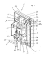
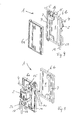
- a heating module 1 for a hot beverage machine or a hot beverage machine is shown.
- a heating module 1 is used in a coffee machine.
- the heating module 1 comprises a pump 2 for conveying the water, a heater 3 for heating the water and a line system for connecting the pump 2 and the heater 3 with a fresh water supply 4 on the one hand and a hot water outlet 5 on the other.
- the heating module 1 consists of two unitary, flat cassette-like half-shells 6a, 6b made of plastic.
- the cassette-like half-shells 6a, 6b are in an assembled position (see Figure 1 to 3 such as FIG. 6 and 7 ) a first cavity 7 for a heating element 3 and a second cavity 8 as a fluid chamber.
- a third cavity 9 is provided as a fresh water inlet chamber.
- the fresh water inlet 4 is connected directly to the input of the pump 2.
- the pump 2 is arranged on the outside of the first half-shell 6a or attached.
- the pump is on the input side (at 10) connected to an output 11 of the third cavity 9 and the output side (at 12) to an input 19 of the first cavity 7.
- the pump 2 is connected on the output side (at 12) to the input 19 of the first cavity 7.
- the first cavity 7 has a first outlet 13, which forms the outlet 5 for heated water.
- the first cavity 7 has a second outlet 14 which is connected by a valve 15 to an inlet 16 of the second cavity 8.
- the third cavity 9 has an inlet 17 for the fresh water supply 4.
- the second cavity 8 has an outlet 18 for dispensing excess water or condensate supplied through the valve 15.
- the second cavity 8 is designed as an expansion and condensation chamber.
- the cassette-like half shells 6a, 6b of the heating module 1, as can be seen from the figures, preferably have a cuboid design.
- all cavities 7,8,9 are arranged to extend approximately parallel to the longitudinal sides of the cuboid shape and the inlets 16,17,19 of the cavities 7,8,9 near a first transverse side and the outlets 11,13,14,18 close to each opposite transverse side of the rectangular shape arranged.
- a very effective distribution of the cavities 7,8,9 and arranged at or near the cavities 7,8,9 arranged elements In the embodiment according to Figure 1 to 5 is near the third cavity 9, which is connected to the fresh water supply 4, a flow meter 21 is arranged.
- the embodiment the embodiment, the
- the flow meter 21 is formed by an ultrasonic flow meter.
- the flowmeter 21 may also be formed by a pressure sensor flowmeter. Other embodiments are possible.
- a circuit board 22 with an evaluation and control electronics for controlling and / or evaluation of electrical signals of the pump 2 and / or the heater 3 is arranged on the first cassette-like half-shell 6a.
- the evaluation electronics can also evaluate and / or control the acquired data of further components of the heating module 1.
- the circuit board 22 is arranged on a cooling body 23, which protrudes from the first cassette-like half-shell 6a to the outside and with a partial area, the wall of the first cassette-like half-shell 6a passes through and lies within the third cavity 9 and there from the fresh water flows around or can be flowed around.
- machine supplied fresh water flows around the parts of the heat sink 23, which pass through the wall and thus absorbs heat released from the heat sink 23 to the fresh water.
- the fresh water is slightly preheated, and on the other hand, the resulting heat on the board 22 through the heat sink 23 dissipated.
- overheating of the board 22 is effectively prevented.
- the pump 2 for conveying the water is formed in the embodiment by an oscillating piston pump arranged thereon pressure accumulator for the compensation of pressure peaks.
- the pump 2 may also be formed by a rotary piston pump with or without pressure accumulator.
- the heating element 3 is disposed within the first cavity 7 and formed by a tubular heater, which is flowed around by fresh water.
- the heating element 3 may also be formed by an induction heating element or a heating cartridge.
- the pump 2 is as in particular off FIG. 1 and FIG. 3 seen with a first tube section 24 on the input side (at 10) with the output 11 of the third cavity 9 and on the output side (at 12) by means of a second hose section 25 connected to the input 19 of the first cavity 7.
- a heating module 1 is usually prefabricated and functionally tested and then installed in the hot beverage machine or the hot beverage machines.
- a pressure relief valve 26 is switched on, which has a discharge port 27, which is connected in the embodiment by means of a further hose section 28 with a collecting container within the hot beverage machine or the hot drinks machine.
- a first temperature sensor 29 for detecting the fresh water temperature and at the heating output (at 13) is a second in the course of the water flow, in the embodiment at the heating input (at 17)
- Temperature sensor 30 arranged to detect the hot water temperature.
- the temperature sensors 29, 30 are connected to the evaluation and control electronics on the board 22 and controllable.
- the evaluation and control electronics can control the detection of the temperatures by the temperature sensors 29, 30, for example, the flow rate of the pump 2 or the heating power of the heater 3 to achieve a desired temperature at the hot water outlet.
- the valve 15 between the input 16 of the second cavity 8 and the second output 14 of the first cavity 7 is connected to the evaluation and control electronics on the board 22 and controllable by this.
- the control or opening of the valve 15 allows the delivery of excess hot water or hot steam near the H thoroughlywasserauslasses 5, whereby on the one hand a possible dripping after the beverage dispensing and on the other hand damage to the corresponding components is avoided.
- this is a targeted relaxation of pressurized hot water or hot steam in the second cavity 8 in, which is designed as an expansion and condensation chamber allows.
- the cuboid half-shells 6a, 6b are pressure-tight with one another in the assembly position connected.
- the bonding can be done for example by means of gluing, welding, in particular by means of friction welding, or screwing.
- a further sealing means for example arranged in the form of a flat gasket.
- the half-shells 6a, 6b are pressure-tight and fluid-tightly connected to one another by friction welding.
- the cavities 7, 8, 9 are formed by depressions formed on one or both half-shells 6a, 6b.
- the first cavity 7 and the second cavity 8 are formed by congruent depressions on the half-shells 6a, 6b. After connecting the half-shells 6a, 6b, the depressions form the fluid-tight and pressure-tight cavities 7, 8, 9.
- the heating element 3 arranged in the first cavity 7 has connecting elements 31, 32 on each end face.
- the connecting elements 31, 32 are sealed relative to the first cavity 7 out of the cavity 7, the half-shells 6a, 6b cross-out, arranged.
- FIG. 3 A corresponding water flow through a heating module 1 according to the invention is shown in FIG. 3 illustrated by appropriate arrows and also in FIG. 7 represented by arrows. The function is explained in more detail below.
- a difference between the embodiments is that in the embodiment of FIGS. 6 to 9 the heating module 1 is connected to the fresh water supply 4 so that it is connected directly to the input of the pump 2.
- the embodiment according to Figure 1 to 5 Fresh water via the fresh water connection 4 in the corresponding region of the third cavity 9 is supplied. Subsequently, the amount of fresh water supplied is measured by the flow meter 21 and the value transmitted to the provided on the board 22 evaluation and control electronics. After flowing through the third cavity 9 in the arrow direction, the fresh water flows through a first tube section 24 in the pump 2. In the embodiment according to FIGS. 6 to 9 This first tube section 24 is connected directly to the fresh water connection 4.
- the fresh water After leaving the pump 2, the fresh water enters a pressure relief valve 26, which has a discharge port 27, by means of a hose section 28 in the event of an unplanned operating pressure, for example, can discharge the water into a collecting container.
- the pressure relief valve 26 is connected to a second tube portion 25 with the input of the first cavity 7, in which the heating element 3 is arranged. With proper pressure within the system, the fresh water will be sent to the entrance to the heater 3.
- a first temperature sensor 29 for detecting the heating input side temperature is arranged.
- a second temperature sensor 30 is arranged on the output side of the heater 3, which measures the water temperature to be delivered.
- the temperatures detected by the temperature sensors 29, 30 are detected by the evaluation and control electronics arranged on the board 22 and evaluated accordingly, for example in order to correspondingly control the flow rate of the pump 2 or the heating power of the heater 3, so that a desired target temperature at the hot water outlet 5 is achieved.
Landscapes
- Engineering & Computer Science (AREA)
- Food Science & Technology (AREA)
- Apparatus For Making Beverages (AREA)
Applications Claiming Priority (1)
| Application Number | Priority Date | Filing Date | Title |
|---|---|---|---|
| DE201110102431 DE102011102431B4 (de) | 2011-05-25 | 2011-05-25 | Heizungsmodul für eine Heißgetränkemaschine oder einen Heißgetränkeautomaten |
Publications (2)
| Publication Number | Publication Date |
|---|---|
| EP2526841A1 true EP2526841A1 (fr) | 2012-11-28 |
| EP2526841B1 EP2526841B1 (fr) | 2013-06-05 |
Family
ID=46026603
Family Applications (1)
| Application Number | Title | Priority Date | Filing Date |
|---|---|---|---|
| EP20120003911 Active EP2526841B1 (fr) | 2011-05-25 | 2012-05-18 | Module de chauffage pour une machine de boissons chaudes ou un automate de boissons chaudes |
Country Status (2)
| Country | Link |
|---|---|
| EP (1) | EP2526841B1 (fr) |
| DE (1) | DE102011102431B4 (fr) |
Cited By (4)
| Publication number | Priority date | Publication date | Assignee | Title |
|---|---|---|---|---|
| EP3323326A1 (fr) * | 2016-11-18 | 2018-05-23 | WMF Group GmbH | Appareil de préparation de boissons ainsi que procédé de commande ou de réglage d'une préparation de boissons |
| WO2019072519A1 (fr) * | 2017-10-09 | 2019-04-18 | Wmf Group Gmbh | Dispositif de préparation de boissons et procédé pour la détermination de quantités d'eau chaude distribuées par un dispositif de préparation de boissons et/ou utilisées dans celui-ci pour la préparation de boissons |
| USD899195S1 (en) | 2018-10-12 | 2020-10-20 | Rich Products Corporation | Food product dispenser |
| US12336656B2 (en) | 2018-10-15 | 2025-06-24 | Rich Products Corporation | Food product dispenser with temperature control |
Citations (4)
| Publication number | Priority date | Publication date | Assignee | Title |
|---|---|---|---|---|
| DE3709256A1 (de) | 1987-03-20 | 1988-09-29 | Krups Stiftung | Elektrisch betriebene maschine zum zubereiten von heissgetraenken, wie kaffee, tee od. dgl. |
| EP2027799A1 (fr) * | 2007-08-22 | 2009-02-25 | Delica AG | Dispositif pour préparer une denrée liquide alimentaire ou de luxe |
| WO2009156190A1 (fr) * | 2008-06-27 | 2009-12-30 | Compagnie Mediterraneenne Des Cafes | Chaudiere pour machine de preparation de boissons chaudes |
| DE102009006577A1 (de) | 2009-01-29 | 2010-08-05 | Bleckmann Gmbh & Co. Kg | Heizsystem mit Heizeinheit und integrierter Pumpe |
Family Cites Families (3)
| Publication number | Priority date | Publication date | Assignee | Title |
|---|---|---|---|---|
| DE1269259B (de) * | 1965-03-18 | 1968-05-30 | Siemens Elektrogeraete Gmbh | Elektrische Heizvorrichtung fuer Wasser, insbesondere fuer Kaffeemaschinen |
| DE19651087C2 (de) * | 1996-12-09 | 2002-06-20 | Bsh Bosch Siemens Hausgeraete | Heizblock mit Gehäuseschalen |
| ITMI20052151A1 (it) * | 2005-11-11 | 2007-05-12 | De Longhi Spa | Caldaia per macchina automatica per la produzione di una bevanda a base di caffe' |
-
2011
- 2011-05-25 DE DE201110102431 patent/DE102011102431B4/de not_active Expired - Fee Related
-
2012
- 2012-05-18 EP EP20120003911 patent/EP2526841B1/fr active Active
Patent Citations (4)
| Publication number | Priority date | Publication date | Assignee | Title |
|---|---|---|---|---|
| DE3709256A1 (de) | 1987-03-20 | 1988-09-29 | Krups Stiftung | Elektrisch betriebene maschine zum zubereiten von heissgetraenken, wie kaffee, tee od. dgl. |
| EP2027799A1 (fr) * | 2007-08-22 | 2009-02-25 | Delica AG | Dispositif pour préparer une denrée liquide alimentaire ou de luxe |
| WO2009156190A1 (fr) * | 2008-06-27 | 2009-12-30 | Compagnie Mediterraneenne Des Cafes | Chaudiere pour machine de preparation de boissons chaudes |
| DE102009006577A1 (de) | 2009-01-29 | 2010-08-05 | Bleckmann Gmbh & Co. Kg | Heizsystem mit Heizeinheit und integrierter Pumpe |
Cited By (10)
| Publication number | Priority date | Publication date | Assignee | Title |
|---|---|---|---|---|
| EP3323326A1 (fr) * | 2016-11-18 | 2018-05-23 | WMF Group GmbH | Appareil de préparation de boissons ainsi que procédé de commande ou de réglage d'une préparation de boissons |
| EP3323326B1 (fr) | 2016-11-18 | 2020-11-25 | WMF Group GmbH | Appareil de préparation de boissons ainsi que procédé de commande ou de réglage d'une préparation de boissons |
| WO2019072519A1 (fr) * | 2017-10-09 | 2019-04-18 | Wmf Group Gmbh | Dispositif de préparation de boissons et procédé pour la détermination de quantités d'eau chaude distribuées par un dispositif de préparation de boissons et/ou utilisées dans celui-ci pour la préparation de boissons |
| CN111200959A (zh) * | 2017-10-09 | 2020-05-26 | 福腾宝集团有限公司 | 饮料制造机和用于测定由饮料制造机输出的和/或在饮料制造机中使用的用于饮料制备的热水量的方法 |
| JP2020536647A (ja) * | 2017-10-09 | 2020-12-17 | ヴェーエムエフ・グループ・ゲゼルシャフト・ミト・ベシュレンクテル・ハフツング | 飲料製造器ならびに飲料製造器によって産出されるおよび/または飲料調製のために飲料製造器において使用される温水量を決定するための方法 |
| JP2024009113A (ja) * | 2017-10-09 | 2024-01-19 | ヴェーエムエフ ゲゼルシャフト ミット ベシュレンクテル ハフツング | 飲料製造器ならびに飲料製造器によって産出されるおよび/または飲料調製のために飲料製造器において使用される温水量を決定するための方法 |
| US12070153B2 (en) | 2017-10-09 | 2024-08-27 | Wmf Gmbh | Beverage maker and method for determining hot water amounts output by a beverage maker and/or used in same for beverage preparation |
| JP7576682B2 (ja) | 2017-10-09 | 2024-10-31 | ヴェーエムエフ ゲゼルシャフト ミット ベシュレンクテル ハフツング | 飲料製造器ならびに飲料製造器によって産出されるおよび/または飲料調製のために飲料製造器において使用される温水量を決定するための方法 |
| USD899195S1 (en) | 2018-10-12 | 2020-10-20 | Rich Products Corporation | Food product dispenser |
| US12336656B2 (en) | 2018-10-15 | 2025-06-24 | Rich Products Corporation | Food product dispenser with temperature control |
Also Published As
| Publication number | Publication date |
|---|---|
| DE102011102431B4 (de) | 2013-08-08 |
| EP2526841B1 (fr) | 2013-06-05 |
| DE102011102431A1 (de) | 2012-11-29 |
Similar Documents
| Publication | Publication Date | Title |
|---|---|---|
| DE112014005441B4 (de) | Koaxiale Ventilanordnung | |
| EP2312224B1 (fr) | Pompe à chaleur dotée d'un module hydraulique | |
| DE102009016601B4 (de) | Filtereinrichtung für Fluide, insbesondere für Kraftstoffe | |
| EP2526841B1 (fr) | Module de chauffage pour une machine de boissons chaudes ou un automate de boissons chaudes | |
| EP2397777B1 (fr) | Unité de boîtier pour une installation de chauffage | |
| EP2524634B1 (fr) | Automate à boissons | |
| DE19509536A1 (de) | Kältemittelaufnahmetank-Baueinheit | |
| EP1936298A2 (fr) | Dispositif de protection de siphon contre le gel | |
| EP3914872B1 (fr) | Module d'échangeur thermique, système d'échangeur thermique et procédé de fabrication du système d'échangeur thermique | |
| WO2005072586A1 (fr) | Machine a cafe comportant un chauffe-eau instantane | |
| EP1532905A1 (fr) | Dispositif pour alimenter de l'eau chaude, de la vapeur ou du lait chaud à une machine à café | |
| DE202020103928U1 (de) | Wohnungsanschlussstation | |
| DE102008051091B3 (de) | Plattenwärmeübertrager und eine Anordnung aus einem solchen und einer Fluidheizung | |
| EP3933349B1 (fr) | Dispositif de mesure de débit volumique et module de chauffage d'eau doté d'un tel dispositif | |
| EP1713364A1 (fr) | Machine a cafe pourvue d'un chauffe-eau instantane | |
| EP2672216B1 (fr) | Échangeur de chaleur | |
| DE102014009327A1 (de) | Filtereinrichtung, insbesondere Flüssigkeitsfilter | |
| DE19948767A1 (de) | Flüssigkeitsfilter mit Schlauchstutzen als Anschluß | |
| EP2293005B1 (fr) | Surveillance d'écoulement d'un échangeur thermique | |
| WO2005072584A1 (fr) | Machine a cafe comportant un chauffe-eau instantane | |
| DE3200474C2 (de) | Elektrischer Durchlauferhitzer | |
| EP1528328B1 (fr) | Module pour installation de chauffage compacte | |
| DE102024107068B4 (de) | Systemtrennereinheit | |
| DE102019214840A1 (de) | Anordnung eines Getriebes und eines Wärmeübertragers | |
| DE102010053568A1 (de) | Ölluftkühler |
Legal Events
| Date | Code | Title | Description |
|---|---|---|---|
| PUAI | Public reference made under article 153(3) epc to a published international application that has entered the european phase |
Free format text: ORIGINAL CODE: 0009012 |
|
| 17P | Request for examination filed |
Effective date: 20120906 |
|
| AK | Designated contracting states |
Kind code of ref document: A1 Designated state(s): AL AT BE BG CH CY CZ DE DK EE ES FI FR GB GR HR HU IE IS IT LI LT LU LV MC MK MT NL NO PL PT RO RS SE SI SK SM TR |
|
| AX | Request for extension of the european patent |
Extension state: BA ME |
|
| GRAP | Despatch of communication of intention to grant a patent |
Free format text: ORIGINAL CODE: EPIDOSNIGR1 |
|
| RIC1 | Information provided on ipc code assigned before grant |
Ipc: A47J 31/54 20060101AFI20130102BHEP |
|
| GRAS | Grant fee paid |
Free format text: ORIGINAL CODE: EPIDOSNIGR3 |
|
| GRAA | (expected) grant |
Free format text: ORIGINAL CODE: 0009210 |
|
| AK | Designated contracting states |
Kind code of ref document: B1 Designated state(s): AL AT BE BG CH CY CZ DE DK EE ES FI FR GB GR HR HU IE IS IT LI LT LU LV MC MK MT NL NO PL PT RO RS SE SI SK SM TR |
|
| REG | Reference to a national code |
Ref country code: GB Ref legal event code: FG4D Free format text: NOT ENGLISH |
|
| REG | Reference to a national code |
Ref country code: CH Ref legal event code: EP Ref country code: CH Ref legal event code: NV Representative=s name: TROESCH SCHEIDEGGER WERNER AG, CH |
|
| REG | Reference to a national code |
Ref country code: AT Ref legal event code: REF Ref document number: 615140 Country of ref document: AT Kind code of ref document: T Effective date: 20130615 |
|
| REG | Reference to a national code |
Ref country code: IE Ref legal event code: FG4D Free format text: LANGUAGE OF EP DOCUMENT: GERMAN |
|
| REG | Reference to a national code |
Ref country code: DE Ref legal event code: R096 Ref document number: 502012000028 Country of ref document: DE Effective date: 20130801 |
|
| PG25 | Lapsed in a contracting state [announced via postgrant information from national office to epo] |
Ref country code: LT Free format text: LAPSE BECAUSE OF FAILURE TO SUBMIT A TRANSLATION OF THE DESCRIPTION OR TO PAY THE FEE WITHIN THE PRESCRIBED TIME-LIMIT Effective date: 20130605 Ref country code: SI Free format text: LAPSE BECAUSE OF FAILURE TO SUBMIT A TRANSLATION OF THE DESCRIPTION OR TO PAY THE FEE WITHIN THE PRESCRIBED TIME-LIMIT Effective date: 20130605 Ref country code: ES Free format text: LAPSE BECAUSE OF FAILURE TO SUBMIT A TRANSLATION OF THE DESCRIPTION OR TO PAY THE FEE WITHIN THE PRESCRIBED TIME-LIMIT Effective date: 20130916 Ref country code: GR Free format text: LAPSE BECAUSE OF FAILURE TO SUBMIT A TRANSLATION OF THE DESCRIPTION OR TO PAY THE FEE WITHIN THE PRESCRIBED TIME-LIMIT Effective date: 20130906 Ref country code: FI Free format text: LAPSE BECAUSE OF FAILURE TO SUBMIT A TRANSLATION OF THE DESCRIPTION OR TO PAY THE FEE WITHIN THE PRESCRIBED TIME-LIMIT Effective date: 20130605 Ref country code: SE Free format text: LAPSE BECAUSE OF FAILURE TO SUBMIT A TRANSLATION OF THE DESCRIPTION OR TO PAY THE FEE WITHIN THE PRESCRIBED TIME-LIMIT Effective date: 20130605 Ref country code: NO Free format text: LAPSE BECAUSE OF FAILURE TO SUBMIT A TRANSLATION OF THE DESCRIPTION OR TO PAY THE FEE WITHIN THE PRESCRIBED TIME-LIMIT Effective date: 20130905 |
|
| REG | Reference to a national code |
Ref country code: NL Ref legal event code: VDEP Effective date: 20130605 |
|
| REG | Reference to a national code |
Ref country code: LT Ref legal event code: MG4D |
|
| PG25 | Lapsed in a contracting state [announced via postgrant information from national office to epo] |
Ref country code: BG Free format text: LAPSE BECAUSE OF FAILURE TO SUBMIT A TRANSLATION OF THE DESCRIPTION OR TO PAY THE FEE WITHIN THE PRESCRIBED TIME-LIMIT Effective date: 20130905 Ref country code: HR Free format text: LAPSE BECAUSE OF FAILURE TO SUBMIT A TRANSLATION OF THE DESCRIPTION OR TO PAY THE FEE WITHIN THE PRESCRIBED TIME-LIMIT Effective date: 20130605 Ref country code: RS Free format text: LAPSE BECAUSE OF FAILURE TO SUBMIT A TRANSLATION OF THE DESCRIPTION OR TO PAY THE FEE WITHIN THE PRESCRIBED TIME-LIMIT Effective date: 20130605 |
|
| PG25 | Lapsed in a contracting state [announced via postgrant information from national office to epo] |
Ref country code: LV Free format text: LAPSE BECAUSE OF FAILURE TO SUBMIT A TRANSLATION OF THE DESCRIPTION OR TO PAY THE FEE WITHIN THE PRESCRIBED TIME-LIMIT Effective date: 20130605 |
|
| PG25 | Lapsed in a contracting state [announced via postgrant information from national office to epo] |
Ref country code: EE Free format text: LAPSE BECAUSE OF FAILURE TO SUBMIT A TRANSLATION OF THE DESCRIPTION OR TO PAY THE FEE WITHIN THE PRESCRIBED TIME-LIMIT Effective date: 20130605 Ref country code: IS Free format text: LAPSE BECAUSE OF FAILURE TO SUBMIT A TRANSLATION OF THE DESCRIPTION OR TO PAY THE FEE WITHIN THE PRESCRIBED TIME-LIMIT Effective date: 20131005 Ref country code: PT Free format text: LAPSE BECAUSE OF FAILURE TO SUBMIT A TRANSLATION OF THE DESCRIPTION OR TO PAY THE FEE WITHIN THE PRESCRIBED TIME-LIMIT Effective date: 20131007 Ref country code: SK Free format text: LAPSE BECAUSE OF FAILURE TO SUBMIT A TRANSLATION OF THE DESCRIPTION OR TO PAY THE FEE WITHIN THE PRESCRIBED TIME-LIMIT Effective date: 20130605 Ref country code: CZ Free format text: LAPSE BECAUSE OF FAILURE TO SUBMIT A TRANSLATION OF THE DESCRIPTION OR TO PAY THE FEE WITHIN THE PRESCRIBED TIME-LIMIT Effective date: 20130605 |
|
| PG25 | Lapsed in a contracting state [announced via postgrant information from national office to epo] |
Ref country code: NL Free format text: LAPSE BECAUSE OF FAILURE TO SUBMIT A TRANSLATION OF THE DESCRIPTION OR TO PAY THE FEE WITHIN THE PRESCRIBED TIME-LIMIT Effective date: 20130605 Ref country code: PL Free format text: LAPSE BECAUSE OF FAILURE TO SUBMIT A TRANSLATION OF THE DESCRIPTION OR TO PAY THE FEE WITHIN THE PRESCRIBED TIME-LIMIT Effective date: 20130605 Ref country code: RO Free format text: LAPSE BECAUSE OF FAILURE TO SUBMIT A TRANSLATION OF THE DESCRIPTION OR TO PAY THE FEE WITHIN THE PRESCRIBED TIME-LIMIT Effective date: 20130605 |
|
| PLBE | No opposition filed within time limit |
Free format text: ORIGINAL CODE: 0009261 |
|
| STAA | Information on the status of an ep patent application or granted ep patent |
Free format text: STATUS: NO OPPOSITION FILED WITHIN TIME LIMIT |
|
| PG25 | Lapsed in a contracting state [announced via postgrant information from national office to epo] |
Ref country code: DK Free format text: LAPSE BECAUSE OF FAILURE TO SUBMIT A TRANSLATION OF THE DESCRIPTION OR TO PAY THE FEE WITHIN THE PRESCRIBED TIME-LIMIT Effective date: 20130605 |
|
| 26N | No opposition filed |
Effective date: 20140306 |
|
| REG | Reference to a national code |
Ref country code: DE Ref legal event code: R097 Ref document number: 502012000028 Country of ref document: DE Effective date: 20140306 |
|
| PG25 | Lapsed in a contracting state [announced via postgrant information from national office to epo] |
Ref country code: LU Free format text: LAPSE BECAUSE OF FAILURE TO SUBMIT A TRANSLATION OF THE DESCRIPTION OR TO PAY THE FEE WITHIN THE PRESCRIBED TIME-LIMIT Effective date: 20140518 |
|
| PG25 | Lapsed in a contracting state [announced via postgrant information from national office to epo] |
Ref country code: MC Free format text: LAPSE BECAUSE OF FAILURE TO SUBMIT A TRANSLATION OF THE DESCRIPTION OR TO PAY THE FEE WITHIN THE PRESCRIBED TIME-LIMIT Effective date: 20130605 |
|
| REG | Reference to a national code |
Ref country code: IE Ref legal event code: MM4A |
|
| PG25 | Lapsed in a contracting state [announced via postgrant information from national office to epo] |
Ref country code: IE Free format text: LAPSE BECAUSE OF NON-PAYMENT OF DUE FEES Effective date: 20140518 |
|
| PG25 | Lapsed in a contracting state [announced via postgrant information from national office to epo] |
Ref country code: MT Free format text: LAPSE BECAUSE OF FAILURE TO SUBMIT A TRANSLATION OF THE DESCRIPTION OR TO PAY THE FEE WITHIN THE PRESCRIBED TIME-LIMIT Effective date: 20130605 |
|
| PG25 | Lapsed in a contracting state [announced via postgrant information from national office to epo] |
Ref country code: SM Free format text: LAPSE BECAUSE OF FAILURE TO SUBMIT A TRANSLATION OF THE DESCRIPTION OR TO PAY THE FEE WITHIN THE PRESCRIBED TIME-LIMIT Effective date: 20130605 |
|
| REG | Reference to a national code |
Ref country code: FR Ref legal event code: PLFP Year of fee payment: 5 |
|
| PG25 | Lapsed in a contracting state [announced via postgrant information from national office to epo] |
Ref country code: CY Free format text: LAPSE BECAUSE OF FAILURE TO SUBMIT A TRANSLATION OF THE DESCRIPTION OR TO PAY THE FEE WITHIN THE PRESCRIBED TIME-LIMIT Effective date: 20130605 |
|
| PG25 | Lapsed in a contracting state [announced via postgrant information from national office to epo] |
Ref country code: BE Free format text: LAPSE BECAUSE OF FAILURE TO SUBMIT A TRANSLATION OF THE DESCRIPTION OR TO PAY THE FEE WITHIN THE PRESCRIBED TIME-LIMIT Effective date: 20140531 Ref country code: TR Free format text: LAPSE BECAUSE OF FAILURE TO SUBMIT A TRANSLATION OF THE DESCRIPTION OR TO PAY THE FEE WITHIN THE PRESCRIBED TIME-LIMIT Effective date: 20130605 Ref country code: HU Free format text: LAPSE BECAUSE OF FAILURE TO SUBMIT A TRANSLATION OF THE DESCRIPTION OR TO PAY THE FEE WITHIN THE PRESCRIBED TIME-LIMIT; INVALID AB INITIO Effective date: 20120518 |
|
| REG | Reference to a national code |
Ref country code: FR Ref legal event code: PLFP Year of fee payment: 6 |
|
| REG | Reference to a national code |
Ref country code: FR Ref legal event code: PLFP Year of fee payment: 7 |
|
| PG25 | Lapsed in a contracting state [announced via postgrant information from national office to epo] |
Ref country code: MK Free format text: LAPSE BECAUSE OF FAILURE TO SUBMIT A TRANSLATION OF THE DESCRIPTION OR TO PAY THE FEE WITHIN THE PRESCRIBED TIME-LIMIT Effective date: 20130605 |
|
| PG25 | Lapsed in a contracting state [announced via postgrant information from national office to epo] |
Ref country code: AL Free format text: LAPSE BECAUSE OF FAILURE TO SUBMIT A TRANSLATION OF THE DESCRIPTION OR TO PAY THE FEE WITHIN THE PRESCRIBED TIME-LIMIT Effective date: 20130605 |
|
| P01 | Opt-out of the competence of the unified patent court (upc) registered |
Effective date: 20230509 |
|
| PGFP | Annual fee paid to national office [announced via postgrant information from national office to epo] |
Ref country code: IT Payment date: 20230525 Year of fee payment: 12 Ref country code: CH Payment date: 20230701 Year of fee payment: 12 |
|
| PGFP | Annual fee paid to national office [announced via postgrant information from national office to epo] |
Ref country code: AT Payment date: 20230526 Year of fee payment: 12 |
|
| PGFP | Annual fee paid to national office [announced via postgrant information from national office to epo] |
Ref country code: GB Payment date: 20230530 Year of fee payment: 12 |
|
| PGFP | Annual fee paid to national office [announced via postgrant information from national office to epo] |
Ref country code: FR Payment date: 20240523 Year of fee payment: 13 |
|
| PGFP | Annual fee paid to national office [announced via postgrant information from national office to epo] |
Ref country code: DE Payment date: 20240731 Year of fee payment: 13 |
|
| REG | Reference to a national code |
Ref country code: CH Ref legal event code: PL |
|
| REG | Reference to a national code |
Ref country code: AT Ref legal event code: MM01 Ref document number: 615140 Country of ref document: AT Kind code of ref document: T Effective date: 20240518 |
|
| PG25 | Lapsed in a contracting state [announced via postgrant information from national office to epo] |
Ref country code: AT Free format text: LAPSE BECAUSE OF NON-PAYMENT OF DUE FEES Effective date: 20240518 |
|
| GBPC | Gb: european patent ceased through non-payment of renewal fee |
Effective date: 20240518 |
|
| PG25 | Lapsed in a contracting state [announced via postgrant information from national office to epo] |
Ref country code: AT Free format text: LAPSE BECAUSE OF NON-PAYMENT OF DUE FEES Effective date: 20240518 Ref country code: CH Free format text: LAPSE BECAUSE OF NON-PAYMENT OF DUE FEES Effective date: 20240531 |
|
| PG25 | Lapsed in a contracting state [announced via postgrant information from national office to epo] |
Ref country code: IT Free format text: LAPSE BECAUSE OF NON-PAYMENT OF DUE FEES Effective date: 20240518 Ref country code: GB Free format text: LAPSE BECAUSE OF NON-PAYMENT OF DUE FEES Effective date: 20240518 |
|
| REG | Reference to a national code |
Ref country code: DE Ref legal event code: R119 Ref document number: 502012000028 Country of ref document: DE |
|
| PG25 | Lapsed in a contracting state [announced via postgrant information from national office to epo] |
Ref country code: DE Free format text: LAPSE BECAUSE OF NON-PAYMENT OF DUE FEES Effective date: 20251202 |
|
| PG25 | Lapsed in a contracting state [announced via postgrant information from national office to epo] |
Ref country code: FR Free format text: LAPSE BECAUSE OF NON-PAYMENT OF DUE FEES Effective date: 20250531 |