EP3323326B1 - Appareil de préparation de boissons ainsi que procédé de commande ou de réglage d'une préparation de boissons - Google Patents
Appareil de préparation de boissons ainsi que procédé de commande ou de réglage d'une préparation de boissons Download PDFInfo
- Publication number
- EP3323326B1 EP3323326B1 EP17193461.5A EP17193461A EP3323326B1 EP 3323326 B1 EP3323326 B1 EP 3323326B1 EP 17193461 A EP17193461 A EP 17193461A EP 3323326 B1 EP3323326 B1 EP 3323326B1
- Authority
- EP
- European Patent Office
- Prior art keywords
- fluid
- flow
- beverage
- milk
- making machine
- Prior art date
- Legal status (The legal status is an assumption and is not a legal conclusion. Google has not performed a legal analysis and makes no representation as to the accuracy of the status listed.)
- Active
Links
Images



Classifications
-
- A—HUMAN NECESSITIES
- A47—FURNITURE; DOMESTIC ARTICLES OR APPLIANCES; COFFEE MILLS; SPICE MILLS; SUCTION CLEANERS IN GENERAL
- A47J—KITCHEN EQUIPMENT; COFFEE MILLS; SPICE MILLS; APPARATUS FOR MAKING BEVERAGES
- A47J31/00—Apparatus for making beverages
- A47J31/44—Parts or details or accessories of beverage-making apparatus
- A47J31/46—Dispensing spouts, pumps, drain valves or like liquid transporting devices
- A47J31/469—Details of hydraulic circuits
-
- A—HUMAN NECESSITIES
- A47—FURNITURE; DOMESTIC ARTICLES OR APPLIANCES; COFFEE MILLS; SPICE MILLS; SUCTION CLEANERS IN GENERAL
- A47J—KITCHEN EQUIPMENT; COFFEE MILLS; SPICE MILLS; APPARATUS FOR MAKING BEVERAGES
- A47J31/00—Apparatus for making beverages
- A47J31/44—Parts or details or accessories of beverage-making apparatus
- A47J31/52—Alarm-clock-controlled mechanisms for coffee- or tea-making apparatus ; Timers for coffee- or tea-making apparatus; Electronic control devices for coffee- or tea-making apparatus
- A47J31/525—Alarm-clock-controlled mechanisms for coffee- or tea-making apparatus ; Timers for coffee- or tea-making apparatus; Electronic control devices for coffee- or tea-making apparatus the electronic control being based on monitoring of specific process parameters
- A47J31/5253—Alarm-clock-controlled mechanisms for coffee- or tea-making apparatus ; Timers for coffee- or tea-making apparatus; Electronic control devices for coffee- or tea-making apparatus the electronic control being based on monitoring of specific process parameters of temperature
-
- A—HUMAN NECESSITIES
- A47—FURNITURE; DOMESTIC ARTICLES OR APPLIANCES; COFFEE MILLS; SPICE MILLS; SUCTION CLEANERS IN GENERAL
- A47J—KITCHEN EQUIPMENT; COFFEE MILLS; SPICE MILLS; APPARATUS FOR MAKING BEVERAGES
- A47J31/00—Apparatus for making beverages
- A47J31/44—Parts or details or accessories of beverage-making apparatus
- A47J31/52—Alarm-clock-controlled mechanisms for coffee- or tea-making apparatus ; Timers for coffee- or tea-making apparatus; Electronic control devices for coffee- or tea-making apparatus
- A47J31/525—Alarm-clock-controlled mechanisms for coffee- or tea-making apparatus ; Timers for coffee- or tea-making apparatus; Electronic control devices for coffee- or tea-making apparatus the electronic control being based on monitoring of specific process parameters
- A47J31/5255—Alarm-clock-controlled mechanisms for coffee- or tea-making apparatus ; Timers for coffee- or tea-making apparatus; Electronic control devices for coffee- or tea-making apparatus the electronic control being based on monitoring of specific process parameters of flow rate
Definitions
- a temperature detection according to the prior art usually takes place with an additional thermistor element or PTC thermistor element, which is usually placed in the medium.
- Such known measurement methods offer no additional benefit through e.g. Detecting air bubbles or measuring the temperature. Additional sensors are required for this, which require additional installation space and additional inputs on the electronic control unit. Furthermore, these sensors are sometimes sluggish, with a correspondingly long response time or to be supported with complex calculation models.
- the EP 2 526 841 A1 discloses a heating module for a hot beverage machine containing a measuring system for detecting a fluid flow, the measuring system containing a flow meter.
- the WO 2006/052969 A2 discloses a beverage maker containing a measuring system for detecting a fluid flow, the measuring system containing a flow meter or a flow meter.
- the ES 2 366 876 T3 and the WO 2012/072724 A1 disclose a beverage maker containing a measuring system for detecting a fluid flow, the measuring system containing a magnetic flux meter with a "Hall" effect sensor.
- the object of the invention is therefore to provide an improved beverage maker as well as an improved method for controlling or regulating the preparation of a beverage, which the o.g. Avoids disadvantages and yet is constructed in the simplest possible way and works reliably.
- a beverage maker according to the invention can be found in claim 1.
- a fluid is generally a liquid, but liquids with gaseous components are also possible. Examples: Milk, cold inlet water, already warmed up brewing water, hot coffee or even warmed up milk with milk froth (possibly even pure milk froth).
- the conveying device is arranged (in a line system of the beverage maker) upstream of the flow measuring system or of parts of the same.
- the conveying device is positioned downstream of the flow measuring system or parts thereof.
- the term flow measuring system is understood very generally: It can be a system with a flow meter, act with a volume counter or with a flow meter that records a volume flow.
- an ultrasonic flow measuring system hereinafter abbreviated: US-DFMS
- MI-DFMS magnetic induction flow measuring system
- the conveying device is in particular a pump.
- the parameter (s) characterizing one / the flow of the fluid can in particular be a speed of the fluid, a flow volume per unit of time, a flowing mass per unit of time, ... of the fluid in a fluid line in the beverage maker or in a housing of the same (or in a suction line outside the housing of the beverage maker).
- a temperature (as a parameter which characterizes an instantaneous state of the fluid) can also be recorded.
- the DFMS also, cf. below, has a temperature sensor.
- this case includes that the DFMS has a flow meter (DFM) and a temperature sensor spatially separated from one another, i.e. at different positions, e.g. within a housing of the beverage maker.
- DFM flow meter
- Such a DFM and such a temperature sensor can work separately from one another, i.e. that the corresponding measured values can be recorded and evaluated separately from one another (e.g. in a central control unit).
- a parameter (“state parameter”) which characterizes the state of the fluid is, according to the invention, a variable which indicates whether or not air bubbles are contained in a liquid as a fluid. It can also be a quantity that indicates both the air and the liquid content in a fluid.
- a parameter characterizing a property of the fluid for example, a density or a viscosity of the fluid can also be recorded with the DFMS.
- a large number of individual measured values can be recorded in chronological succession by the DFMS for each parameter (parameter measured value series).
- an ultrasonic DFM (US-DFM) of the (US-) DFMS determines that the amount of water flowing into a brewing chamber of an electrically operated fully automatic coffee machine (as a beverage maker) is too high at the moment or per unit of time
- the delivery rate of the conveyor can be so long (control) until the US-DFM determines that the amount of water flowing in at the moment or per unit of time corresponds to a predefined setpoint (or it can be regulated in such a way that the measured value series follows a predefined setpoint curve over time).
- Such a target value can also be stored, for example, in a memory of a microcontroller or a computer system of the beverage maker as a target value flow rate curve in which the currently desired flow rate is variably predefined over the entire brewing time curve.
- the beverage maker can thus work program-assisted or computer-assisted and accordingly, e.g. in the form of a microcontroller, also a microprocessor and a memory in which control or regulation programs (which are then executed by the microprocessor) as well as said setpoint curves can be stored.
- valves of the conveying device that may be present in the line system of the beverage maker can also be regulated.
- a combined system of a conveyor and a heater system can also be implemented, for example as a Venturi steam jet pump system for sucking in milk.
- the suction power or the amount of steam per unit of time can be regulated (for example via a valve in a steam supply line).
- the construction of such a Venturi steam jet pump system is known to the person skilled in the art.
- Such a design can take place by using a temperature sensor within the scope of the DFMS, in particular an ultrasound-based flow meter that integrates such a temperature sensor.
- an NTC element or a PTC element can be used as the temperature sensor.
- the recorded e.g. the parameters relating to a flow are usually recorded as volume, mass, quantity, ... per unit of time.
- a large number of measured values can be recorded over a longer time interval (for example over an interval between 1 min and 10 min) and / or at preferably constant time intervals (for example in the range between 1 s and 5 s) over the entire switch-on time or operating time of the beverage maker are recorded (ongoing recording of measured values).
- the metering of the brewing water is preferably a volume or quantity metering and / or is preferably carried out in a brewing chamber of the beverage maker (e.g. in an electrically operated coffee machine as a beverage maker).
- the invention uses an ultrasonic flow meter (abbreviated: US-DFM) as the DFM of the DFMS, hereinafter also referred to alternatively as an ultrasonic sensor or US sensor.
- US-DFM ultrasonic flow meter
- this US-DFM measures the speed of a flowing medium (here: milk, water, milk foam, ...) with the help of acoustic waves (based on the sound speed of the medium). It can comprise two parts: the actual measuring sensor (ultrasonic sensor) and an evaluation and supply part (transmitter or measuring transducer). Most of the time, the transmitter and receiver elements are the same component and are controlled or evaluated alternately by an electronic evaluation and control unit as transmitter or receiver.
- the acoustic flow measurement advantageously used according to the invention offers some advantages over other measurement methods: The measurement is largely independent of the properties of the media used, such as electrical conductivity and viscosity. The lack of moving mechanical parts reduces maintenance costs.
- the measurement setup can be easily integrated into the usual cross-sections of a beverage maker; a pressure loss due to cross-sectional narrowing at the measuring point is negligible. A large measuring range is another positive feature of this approach.
- the ultrasonic transit time method in particular can be used (see below).
- the US flow measurement sensor system offers the possibility, for example, of measuring the milk flow without moving parts.
- the decisive factor here is the idea of using this measuring principle in a beverage maker, especially in coffee machines.
- a control in particular a controlled system, is set up in which the conveying means (fluid) is influenced by the signals from the measuring transducer.
- the energy of a heater system hereinafter also alternatively referred to as a heating device
- a heating device can also be supplied by the signals from the sensor to be influenced.
- the conveying means is preferably regulated by the desired flow rate of the medium, with a fast US-DFM measurement preferably being used as the measuring sensor and / or preferably based on the volume flow and the known flow temperature and / or the measured output temperature the energy supply to the heater system is regulated.
- the heater system can be used as the heater system. These are for example from the WO 2010/133409 A1 known.
- the medium can be heated by means of condensing water vapor.
- the heating output electrical energy or steam energy
- the volume flow can be regulated based on the known heating output by means of measured flow values.
- cooling energy for the preparation of cold beverages can of course also be supplied.
- the speed of sound of the medium can also be measured (e.g. via the transit time) with fast electronic evaluations.
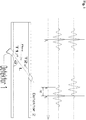
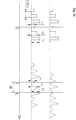
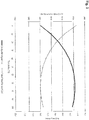
- the speed of sound in the known medium depends on the temperature. From this, the medium temperature can now be determined very quickly in a limited area (see the following example of water) via the transit time measurement. The time between a transmitted transmission pulse and reception of this pulse is measured. This is known in principle, cf. to Figures 1 (temperature-dependent transit times) and 2 (dependence of the speed of sound on the temperature). Out Figure 2 it can be seen that this only makes sense in certain areas.
- the emitted sound waves are usually emitted at a predetermined frequency by the piezo acoustic wave transducer or are predetermined by the microcontroller of the ultrasonic transmitter.
- the delta of the received signal when the temperature changes from 10 ° C to 30 ° C, for example, is several times greater than a transmission pulse length. (Please refer Fig. 1 .)
- the exact transmission pulse cannot be assigned to a single received signal.
- the US sensor element can additionally be equipped with a temperature sensor (for example NTC sensor).
- a temperature sensor for example NTC sensor
- This temperature sensor can be placed in the medium, but in a preferred embodiment also outside the medium, but very close to the medium, for example on a thin pipe wall.
- the temperature at the temperature sensor element thus determines the starting value of the medium temperature.
- a changing temperature in the medium can thus be determined very quickly (regardless of the dead time of the additional temperature sensor element) in a few milliseconds. Only a prominent point in the received signal (maximum value / zero crossing) is followed and its change in transit time compared to the transmitted signals is evaluated.
- the latter in addition to rapid temperature detection with NTC / PTC elements, can also be used to calculate the temperature over at least two to three (or even more) of the measured points.
- the end point can be calculated up to steady-state, which then reflects the current actual temperature of the medium when it flows through the measuring point.
- the response time of the temperature sensor via mass accumulations is thus shortened.
- the basis for this is the fact that, due to delays in the response time of a sensor in its application, the measured temperature asymptotically approaches the actual end value.
- the speed of sound can be determined by means of the additional temperature sensor element and the temperature sensor can be calibrated to the medium.
- the sound velocities of various media are determined by laboratory technology and are therefore known, conclusions can be drawn about the type of medium flowing through, taking the temperature into account.
- the speed of sound can vary depending on the temperature due to the fat content in the milk. If the temperature is known, conclusions can be drawn about the fat content or other parameters (soy milk, ..).
- an additional signal can be modeled (or modulated) onto the transmitted signal so that a pattern can be recognized in the received signals and the individual sine waves can be assigned to a transmission signal (e.g. a transmission edge of the same). This can be done, for example, in the form of varying signal strengths. Another example would be changing the pause times or interruption patterns within the specified frequency f.
- the conveying device can be controlled or regulated or the parameters of the conveying device (e.g. steam pressure in Venturi systems or electrical power or speed at Pump systems). In the simplest case, this is done in a controlling manner, i.e. the beverage maker or (at least) its conveying device is monitored and the parameters can be suitably adapted for subsequent dosing.
- the conveying device is regulated in response to the measurement signals from the US-DFM or the sensor element.
- Disturbances in the fluid e.g. due to air bubbles or other (e.g. CO 2 ) outgassing, can be detected. This is based on the changing speed of sound in the medium. This changes when a fluid is mixed with gases. This also allows conclusions to be drawn about a gas / air proportion in a fluid (e.g. milk foam) or, in the case of very large accumulations of gas, that the storage container is empty. The control / regulation reacts to these signals in the form of empty reporting events or influencing the air supply for a targeted milk foam consistency.
- a fluid e.g. milk foam
- the control / regulation reacts to these signals in the form of empty reporting events or influencing the air supply for a targeted milk foam consistency.
- BagInBox containers in which the milk is aseptically filled, are becoming increasingly interesting for hygienic milk storage.
- the containers empty when the medium is dosed. If the container is empty, air is not sucked in there (as in open milk systems). The funding can simply no longer promote a medium. This effect can be used with the sensor element described above as an empty signal when there is no longer any flow. (In the state of the art, capacitive sensors are used here, for example, which can detect air in a milk hose, but these do not work reliably with BagInBox systems.)
- Another measuring method is magnet-induced in a further variant according to the invention, i.e. with an MI-DFM: Masses flowing through (in a magnetic field) induce current at two electrodes.
- MI-DFM Magnetic In addition to the pure flow measurement, air bubbles can also be quickly identified in the system.
- the beverage maker according to the invention can have a flow channel (through which the fluid flows, in which the parameters are thus recorded), the cross section of which is known.
- the design is advantageous here of the beverage maker in such a way that the detection takes place on (and not: in) the channel, so that no moving parts for flow measurement / volume measurement are introduced into the medium.
- the distance between the sound-emitting transmitter and receiver components of the DFM or DFMS in the flow channel are advantageously known.
- the inlet and outlet channels to this flow channel can advantageously be provided with sufficient radii (see Fig. 3 / R), so that a simple cleaning automated cleaning is possible.
- Ultrasonic frequencies are preferably used to determine the flow rate and the temperature. Magnet-induced measuring methods can also be used to determine the flow velocity (MI-DFM).
- the flow channel used for the measurement in / on the beverage maker is preferably only flowed through in one direction, with the inlet and outlet preferably being able to be (approximately) symmetrically or similarly constructed.
- This flow channel is preferably equipped with hose connectors so that it can be used flexibly in a beverage maker.
- This flow channel and its adjacent media-contacting parts can be made of a non-corrosive, food-grade material, preferably plastic.
- the DFMS or the DFM of the same or at least parts of it is / are preferably between the storage container (milk or water tank) or the fixed water connection (inlet) of the beverage maker and the dispensing point in the direction of the cup (outlet).
- the structure of the DFM or sensor element can have exactly two (or even more than two) hydraulic connections and / or at least one electrical connection for power supply and for outputting measurement signals or measurement data (temperature, flow rate, ).
- the sensor system (DFM or DFMS) can have a controller that converts the recorded signals (e.g. flow signals) into digital signals. Each digital signal can stand for a defined amount of the fluid.
- conveying devices can also be used in one and the same beverage maker be provided for conveying a fluid, each of which includes a flow measuring system for detecting one or more parameters characterizing a flow rate of this fluid, a property of this fluid and / or a condition of this fluid.
- Each such delivery device for example a water pump for the water to be fed to the brewing group and a milk pump
- a beverage maker according to the invention can in particular have a central control unit (with a microcontroller and program memory for control or regulation programs implementing the invention).
- a central control unit with a microcontroller and program memory for control or regulation programs implementing the invention.
- a combination of several sensors (see the immediately preceding paragraph) with this central control is possible.
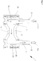
- FIG 3 shows a US-DFMS 4 according to the invention with a US-DFM according to the invention (cf. also Figures 4 and 5 ) that works based on ultrasound.
- the US-DFM of the US-DFMS 4 has a U-shaped pipe section which comprises the elements 20 to 22.
- 20 is a connecting piece (inlet connector) via which the fluid F to be measured (in particular with regard to its flow rate) is fed to the US-DFM.
- FE thus denotes the fluid F introduced into the US-DFM of US-DFMS 4.
- a center piece 21 adjoins the inlet connector 20 downstream of the fluid (with a 90 ° kink in relation to the fluid flow direction).
- the outlet connector 22 connects, via which the fluid F or the US-DFM leaves the US-DFMS 4.
- R symbolizes the rounding of edges and the lack of dead spaces in the fluid-powered area of the US-DFM.
- the conveying means or conveying device 5 Downstream of the fluid flow from the outlet connector 22 is the conveying means or conveying device 5, which can be regulated on the basis of the measurement signals of the US-DFMS 4 shown (cf. Fig. 4 and 5 ).
- the exiting from the US-DFMS 4 (measured, ie one or more of the flow (for the direction of which cf. the arrows in the pipeline) of the fluid F was (are) recorded by the US-DFM parameter (s)) is fluid provided with the reference symbol FA.
- the inlet connector 20 integrates an ultrasonic transmitter-receiver (transceiver) 23a, 24a, with 23a the pressure ring and 24a the piezoceramic of this transceiver (the basic structure of which is known to the person skilled in the art is) represents.
- the pressure ring ensures that the piezo element rests evenly on the housing wall, but a person skilled in the art could also fasten the piezo element evenly to the wall, for example with a potting compound.
- the outlet connector 22 also integrates an ultrasonic transmitter-receiver (transceiver) 23b, 24b of the same design, so that 23b represents the pressure ring and 24b represents the piezoceramic of this transceiver.
- the fluid flow F between the two transceivers is measured in the fluid flow direction
- 23b, 24b acts as a transmitter and 23a, 24a as a receiver
- the fluid flow F between the two transceivers is opposite to the Measure fluid flow direction.
- the switching of the measuring directions takes place by means of the central control unit 6 (cf. Figures 4 and 5 ).
- the sensor 23b, 24b can be switched as a transmitter and the sensor 23a, 24a as a receiver: In this case, measurements are made against the direction of fluid flow.
- a part of the control unit can also be located in the immediate vicinity of the piezo element and thus detached from the central control unit on site in the immediate vicinity of the piezo acoustic transducer or the temperature sensor 9.
- the control unit 6 is then provided with data that have already been processed by the sensor element.
- the ultrasonic flow measuring system 4 shown has a temperature sensor 9 in addition to the US-DFM 20 to 24b described.
- This sensor 9 is integrated in the middle piece 21 and sits on the outside of the pipe or on the outside of the pipe wall of this middle piece 21. With this sensor 9, the temperature measurements already described can be carried out.
- Figure 4 shows in a first embodiment of a fully automatic coffee machine according to the invention the use of the in Figure 3 US-DFMS 4 shown.
- 1 designates the input of the medium to be measured.
- water brewing water or water to be supplied to the brewing group - not shown here
- milk in a second variant of this example it is milk.
- both variants can be implemented together in one and the same beverage maker, in which case at least elements 1, 4, 9, 5, 10 can be present twice, namely once for measuring and regulating the water flow and once for measuring and regulating the milk flow.
- central control unit 6 regulates the water flow and the milk flow independently of one another.
- two US-DFMS or US-DFMS can be present in this exemplary embodiment, which allow the fully automatic coffee machine to record and evaluate both parameters for regulating the water flow and for regulating the milk flow.
- the (single) central control unit 6 then has the necessary number of electrical connections 8 which are connected to these US-DFMs or US-DFMSs or parts thereof.
- the water inlet 1 can be from a fixed water connection or from a tank (water tank).
- milk can be introduced 1 from a milk container or from a "bag-in-box”.
- the respective US-DFMS 4 which in each case integrates a temperature sensor 9, is arranged downstream of the input 1 (see also inlet 20 and outlet 22). Downstream of the systems 4 follows the conveying means (conveying device 5) that can be regulated by means of the recorded parameters, here designed as a water pump or as a milk pump (for example gear pump, oscillating armature pump or vane pump).
- the pump can be controlled in two ways: once (first control mode) as a direct control 12 of the pump 5 based on the (respective) US-DFMS 4 itself, the unit 6 only measuring the flow (of water and / or or milk) and the respective conveyor 5 together with its system 4 independently regulate the flow. Or (cf. electrical connection 8 between the central control unit 6 and the respective conveying means 5) a second control mode can be operated in which the central control unit 6 takes over all of the aforementioned tasks (indirect control):
- the means of the respective US-DFMS 4 including Parameter measured values recorded by the respective sensor 9) (e.g.
- a controllable heater system 10 (heating device) is positioned downstream of the conveying means 5 (when speaking of upstream or downstream, the fluid flow is always meant), so that the water or milk leaving the conveying means 5 enters the associated heating device 10 flows.
- 10 can be a boiler (valve 7 and input 2, see below, are then omitted) and the electrical power supply 11 or the heating output of 10 can be based on the US-DFMS 4, 9 the parameters detected by the water flow control or the measured values of the same are controlled.
- milk 10 can be a flow heater or heat exchanger to which a variable amount of superheated steam is fed from a steam generator (not shown) via input 2 and the valve that can be regulated by means of the measurement results from 4, 9, whereby the milk in 10 is heated accordingly becomes.
- the electrical power supply 11 can therefore be omitted.
- the respective heater system 10 or the heating power of the same can be regulated based on the parameters or the measured values of the same recorded with the respective US-DFMS 4, 9 (for the water flow control or the milk flow control) will.
- the reference numeral 11 thus symbolizes the electrical heating energy supply to the heating device 10 or the regulation of the heating device 10 using the variable electrical heating energy supply 11 (via the control unit 6 via the line 8 to the heating energy supply 11) based on parameters recorded by the DFMS 4.
- the heated fluid (water or milk) leaving the respective heating device flows on the current output side from 10 into the beverage dispenser 3 (the water flows through the brewing group arranged between the heater system 10 and the dispenser 3 - not shown here).
- the valve 7 can be a proportional valve, a magnetically controlled valve or a motor-controlled valve.
- the reference numbers 8 designate bidirectional data and control lines between the central control unit 6 or the CPU of the same on the one hand and the components already described (in both flow control variants) on the other hand: US-DFM or flow measuring part of US-DFMS 4, temperature sensors 9 in the Systems 4, conveyor 5, valve 7 or electrical heating energy supply 11 (the latter to system 10).
- bidirectional data and control lines are also provided between the unit 6 on the one hand and the optional units 5 ', 9' and 9 ". Acquired measurement signals or status reports from the elements 9 ', 5', 9, 4, 5, 11, 7, 10, and 9 "can be transmitted to the unit 6 and the unit 6 can control or regulate these elements 9 ', 5', 9, 4, 5, 11, 7, 10, and 9" .
- the reference symbol 5 ' shows that instead of or in addition to the conveyor device 5, a (further) conveyor device 5' can also be positioned upstream of the respective system 4.
- 9 ′′ shows an optional (possibly additional) temperature sensor downstream of the respective conveying device 5 and downstream of the respective heating device 10.
- the temperature of the fluid leaving the device 10 for example the heated brewing water, if the sensor 9 ′′ is upstream of the Brewing chamber is positioned, or the already brewed coffee, if the sensor 9 ′′ is positioned downstream of the brewing chamber).
- Figure 5 shows, as a second embodiment, a further fully automatic coffee machine according to the invention. Only the regulation of the milk delivery or the milk flow (i.e. not the regulation of the brewing water delivery or the water flow - this takes place as in Fig. 4 ) or for the milk flow measuring system and the milk delivery device. The principle of operation is the same as in the embodiment of FIG Figure 4 so that only the differences are described below. Some of the in Figure 4 however, the features shown in Figure 5 Milk delivery control shown is omitted, other features are designed differently or are added. See the description below.
- the fully automatic coffee machine has a combined conveyor and heater system 5-10 (instead of a separate conveyor device 5 and a heater system 10) Figure 4 ).
- This combined system is designed as a Venturi steam jet pump (which has the reference number 5-10 below, the basic mode of operation of the Venturi principle being known to the person skilled in the art).
- the element 5 ' is omitted (including its connection 8 to the unit 6).
- the control path 12 may or may not be present.
- the electrical heating energy supply 11 (including its data and control connection to the heating device 10 on the one hand and to the unit 6 on the other hand) is also omitted.
- the milk supply and the use of the superheated steam via the valve 7 are designed differently.
- air is supplied (for frothing the milk) 30 to 33.
- the input 1 of the medium milk comes from a "bag-in-box" system 40, from which the milk as to Figure 4 described in a US-DFSM 4 integrating a temperature sensor 9 flows (input 20 and output 22 are not provided with reference numerals here).
- the milk leaving the measuring system 4 enters the Venturi steam jet pump 5-10 on the downstream side of the system 4 (inlet line 37).
- This line 37 opens, like the combined steam-air line 35, into the mixing chamber 36 of the Venturi steam jet pump 5-10.
- the milk is heated in the mixing chamber 36 (using superheated steam) and / or the milk (heated or not heated) is foamed over an air supply.
- the milk whose consistency has been changed in this way, leaves the mixing chamber 36 or the Venturi steam jet pump 5-10 via the outflow line 38, which leads via the outlet 3 into an external vessel (e.g. a cup) not shown here; this is the same as with Figure 4 .
- an external vessel e.g. a cup
- the unit 6 is able to use the flow measurement system 4 (which in turn the temperature sensor 9 integrated, compare Figure 3 ) obtained parameter measurement data (eg instantaneous flow rates and temperatures of the milk flowing through) according to the invention to regulate the combined conveying and heating unit 5-10.
- the air supply 31 and / or the superheated steam supply can also be regulated.
- the degree of opening of valve 32 can be regulated in the same way as the degree of opening of valve 7.
- the air is supplied from a compressed air source 30 via the compressed air line 31 and via the valve 32 as well as the compressed air line section 33 positioned downstream of this valve.
- the superheated steam is supplied from the superheated steam source 2 via the valve 7 into the superheated steam line section 34 arranged downstream of the valve 7.
- the two line sections 33 and 34 unite in a common line section, which forms the inlet side of the mixing chamber 36 or the Venturi steam jet pump 5-10 (the line 37 is thus the milk suction line or the extraction pipe of the pump 5-10, the line 38 the outlet the same).
Landscapes
- Engineering & Computer Science (AREA)
- Food Science & Technology (AREA)
- Physics & Mathematics (AREA)
- Fluid Mechanics (AREA)
- Apparatus For Making Beverages (AREA)
Claims (10)
- Préparateur de boissons, comprenant
un dispositif de transport (5) destiné à transporter un fluide (F), et
un système de mesure de débit (4) destiné à capter un ou plusieurs paramètre(s) caractérisant un débit du fluide (F) ainsi qu'un ou plusieurs paramètre(s) caractérisant un état du fluide (F),
le dispositif de transport (5) pouvant être régulé avec utilisation des paramètres captés,
le système de mesure de débit (4)a) comportant un débitmètre à ultrasons avec lequel au moins un paramètre caractérisant le débit du fluide (F) peut être capté; et/oub) comportant un débitmètre magnéto-inductif avec lequel au moins un paramètre caractérisant le débit du fluide (F) peut être capté,caractérisé en ce que, avec le système de mesure de débit (4), un paramètre peut être capté en tant qu'un ou plusieurs paramètre(s) caractérisant un état du fluide (F), qui indique si des bulles de gaz ou d'air sont contenues dans le fluide (F). - Préparateur de boissons selon la revendication précédente,
caractérisé en ce que
le système de mesure de débit (4) est en plus constitué pour capter une ou plusieurs température(s) en tant qu'un ou plusieurs paramètre(s) caractérisant l'état du fluide (F), et en ce que le dispositif de transport (5) peut être commandé, de préférence régulé, avec utilisation de la ou des plusieurs température(s) captées en plus de l'utilisation du ou des plusieurs paramètre(s) caractérisant le débit du fluide (F). - Préparateur de boissons selon l'une des revendications précédentes,
caractérisé par
un système de chauffage (10), ce système de chauffage (10) pouvant lui aussi, en plus du dispositif de transport (5), au moins être commandé, de préférence même régulé, avec utilisation d'un des paramètres ou des plusieurs paramètre(s) captés,
le système de chauffage (10), de préférence dans une réalisation selon la revendication précédente, pouvant être commandé, de préférence régulé avec utilisation d'une ou des plusieurs températures captées. - Préparateur de boissons selon la revendication précédente,
caractérisé par
un système de transport et de chauffage combiné, en particulier constitué en tant que pompe à jet de vapeur à effet Venturi (5-10), ou comprenant une telle pompe. - Préparateur de boissons selon l'une des revendications précédentes selon une variante avec débitmètre à ultrasons,
caractérisé en ce que
le débitmètre à ultrasons comporte, en particulier intègre, un capteur de température (9) pour capter une ou plusieurs température(s) en tant que paramètre/plusieurs paramètres caractérisant l'état du fluide (F). - Préparateur de boissons selon l'une des revendications précédentes,
caractérisé en ce que,
avec le système de mesure de débit (4), un/des débit(s) volumique(s), un/des débit(s) massique(s), un/des flux volumique(s) et/ou une/des vitesse(s) d'écoulement peut/peuvent être capté(s) en tant qu'un ou plusieurs paramètre(s) caractérisant un/le débit du fluide (F) et/ou
une/des température(s) peut/peuvent être captée(s)
en tant que paramètre ou plusieurs paramètres caractérisant une/des propriété(s) du fluide (F). - Préparateur de boissons selon l'une des revendications précédentes,
caractérisé en ce que
le dispositif de transport (5) est ou comprend un dispositif de transport de lait pour transporter du lait en tant que fluide (F),
en ce que le système de mesure de débit (4) est constitué pour capter un ou plusieurs paramètre(s) caractérisant le débit du lait, une propriété du lait qui s'écoule et/ou un état du lait qui s'écoule, et
en ce que, avec utilisation du/des paramètre(s) captés, le dispositif de transport de lait peut être commandé ou régulé, de préférence peut être commandé ou régulé en ce qui concerne un dosage volumique du lait. - Préparateur de boissons selon l'une des revendications précédentes,
caractérisé en ce que
le dispositif de transport (5) est ou comprend un dispositif de transport d'eau d'infusion pour le transport d'eau d'infusion en tant que fluide (F),
en ce que le système de mesure de débit (4) est constitué pour capter un ou plusieurs paramètre(s) caractérisant le débit de l'eau d'infusion, une propriété de l'eau d'infusion qui s'écoule et/ou un état de l'eau d'infusion qui s'écoule, et
en ce que, avec utilisation du/des paramètre(s) capté(s), le dispositif de transport d'eau d'infusion peut être commandé ou régulé, de préférence peut être commandé ou régulé en ce qui concerne un dosage de l'eau d'infusion. - Préparateur de boissons selon l'une des revendications précédentes,
caractérisé en ce que
le préparateur de boissons est ou comprend :• une machine à café électrique, en particulier une machine à café entièrement automatique,• un mousseur à lait,• un dispositif d'infusion de thé, ou• un distributeur automatique de boissons destiné à distribuer plusieurs boissons chaudes et/ou froides comprenant une ou plusieurs spécialité(s) de café, une ou plusieurs spécialité(s) de thé et/ou une ou plusieurs spécialité(s) de potages à boire. - Procédé destiné à réguler une préparation de boisson, en particulier au moyen d'un préparateur de boissons, comprenant
un transport d'un fluide (F) au moyen d'un dispositif de transport (5), et
un captage d'un ou des plusieurs paramètre(s) caractérisant un débit du fluide (F) et un état du fluide (F), au moyen d'un système de mesure de débit (4),
caractérisé en ce que
le dispositif de transport (5) est régulé, avec utilisation des paramètres captés,
un préparateur de boissons selon l'une des revendications 1 à 9 étant mis en œuvre pour la régulation.
Applications Claiming Priority (1)
| Application Number | Priority Date | Filing Date | Title |
|---|---|---|---|
| DE102016222812.9A DE102016222812A1 (de) | 2016-11-18 | 2016-11-18 | Getränkebereiter sowie Verfahren zum Steuern oder Regeln einer Getränkezubereitung |
Publications (3)
| Publication Number | Publication Date |
|---|---|
| EP3323326A1 EP3323326A1 (fr) | 2018-05-23 |
| EP3323326B1 true EP3323326B1 (fr) | 2020-11-25 |
| EP3323326B2 EP3323326B2 (fr) | 2024-04-24 |
Family
ID=59974227
Family Applications (1)
| Application Number | Title | Priority Date | Filing Date |
|---|---|---|---|
| EP17193461.5A Active EP3323326B2 (fr) | 2016-11-18 | 2017-09-27 | Appareil de préparation de boissons ainsi que procédé de commande ou de réglage d'une préparation de boissons |
Country Status (2)
| Country | Link |
|---|---|
| EP (1) | EP3323326B2 (fr) |
| DE (1) | DE102016222812A1 (fr) |
Cited By (3)
| Publication number | Priority date | Publication date | Assignee | Title |
|---|---|---|---|---|
| US12369741B1 (en) | 2024-01-18 | 2025-07-29 | Sharkninja Operating Llc | Preventing coffee bean grinder jamming |
| US12369744B1 (en) | 2024-01-18 | 2025-07-29 | Sharkninja Operating Llc | Preparation of beverage machines for cold beverage brewing |
| US12575692B2 (en) | 2024-01-18 | 2026-03-17 | Sharkninja Operating Llc | Suggesting coffee bean grind size for beverage machines |
Families Citing this family (6)
| Publication number | Priority date | Publication date | Assignee | Title |
|---|---|---|---|---|
| PL3610763T5 (pl) | 2018-08-16 | 2025-10-13 | Cup&Cino Kaffeesystem-Vertrieb Gmbh & Co. Kg | Ekspres do kawy do przygotowania gorącego napoju |
| CN109730537B (zh) * | 2019-03-27 | 2020-06-23 | 江南大学 | 一种可调参数胶囊咖啡调味系统及方法 |
| DE102019123590A1 (de) * | 2019-09-03 | 2021-03-04 | Franke Kaffeemaschinen Ag | Getränkezubereitungsvorrichtung mit Milchsystem |
| CN111588270B (zh) * | 2020-06-03 | 2024-09-13 | 苏州咖博士咖啡系统科技有限公司 | 一种咖啡机的奶路清洗装置 |
| IT202300000657A1 (it) * | 2023-01-18 | 2024-07-18 | Fluid O Tech Srl | Accessorio sensorizzato per pompe, particolarmente per macchine da caffè |
| DE102023109443A1 (de) * | 2023-04-14 | 2024-10-17 | Eugster/Frismag Ag | Verfahren zum Betrieb einer Getränkezubereitungsvorrichtung mit einer hydraulischen Vorverdichtungseinheit zum Verdichten eines Getränkesubstrats |
Citations (7)
| Publication number | Priority date | Publication date | Assignee | Title |
|---|---|---|---|---|
| EP1676509A1 (fr) | 2004-12-30 | 2006-07-05 | Rhea Vendors S.p.A. | Procédé et dispositif pour le contrôle de la préparation d'infusions |
| GB2429063A (en) | 2005-08-13 | 2007-02-14 | Flownetix Ltd | Low power ultrasonic flow measurement |
| WO2007070037A1 (fr) | 2005-12-12 | 2007-06-21 | Carrier Commerical Refrigeration, Inc. | Detecteur de niveau de concentre |
| EP2526841A1 (fr) | 2011-05-25 | 2012-11-28 | Severin Elektrogeräte GmbH | Module de chauffage pour une machine de boissons chaudes ou un automate de boissons chaudes |
| WO2013064232A1 (fr) | 2011-11-01 | 2013-05-10 | Eversys Sa | Système de préparation de lait ou de mousse de lait dans des distributeurs automatiques de boissons et unité de chauffage |
| WO2013110500A1 (fr) | 2012-01-24 | 2013-08-01 | BSH Bosch und Siemens Hausgeräte GmbH | Dispositif de raccordement d'une évacuation de réservoir conçu pour un dispositif de préparation de boisson |
| DE102014108281A1 (de) | 2014-06-12 | 2015-12-17 | Melitta Professional Coffee Solutions GmbH & Co. KG | Durchflussmessung in einem Heißgetränkeautomaten, insbesondere einem Kaffeevollautomaten |
Family Cites Families (11)
| Publication number | Priority date | Publication date | Assignee | Title |
|---|---|---|---|---|
| ATE175327T1 (de) * | 1995-10-31 | 1999-01-15 | Illycaffe Spa | Verbesserte kaffeemaschine |
| DE10356443A1 (de) * | 2003-12-03 | 2005-07-07 | Digmesa Ag | Verfahren und Vorrichtung zum berührungslosen Messen von Durchflüssen |
| WO2005124292A1 (fr) | 2004-06-16 | 2005-12-29 | Endress + Hauser Flowtec Ag | Capteur de debit a induction magnetique |
| WO2006052969A2 (fr) * | 2004-11-10 | 2006-05-18 | Bunn-O-Matic Corporation | Systeme et procede destines a empecher la surchauffe d'une cuve |
| DE602005004558T2 (de) | 2005-11-11 | 2009-01-22 | Gruppo Cimbali S.P.A. | Automatische Vorrichtung zum Erhitzen und Schäumen von Milch |
| CH707091C1 (de) * | 2007-05-18 | 2015-01-15 | Steiner Ag Weggis | Verfahren und Vorrichtung zur Erzeugung von Milchschaum oder Milchgetränken. |
| ES2366876T3 (es) * | 2007-10-04 | 2011-10-26 | Nestec S.A. | Dispositivo de calentamiento con un termo-bloque integrado para una máquina de preparación de bebidas. |
| DE102009021656A1 (de) | 2009-05-16 | 2010-11-18 | Wmf Württembergische Metallwarenfabrik Ag | Durchlauferhitzer und Verfahren zur Steuerung und Regelung eines solchen |
| JP5881726B2 (ja) * | 2010-12-02 | 2016-03-09 | ネステク ソシエテ アノニム | 飲料装置における低慣性熱センサ |
| DE102012200113B4 (de) * | 2012-01-05 | 2016-07-07 | BSH Hausgeräte GmbH | Heizeinrichtung in einem wasserführenden Haushaltsgerät |
| DE102013224786B3 (de) | 2013-12-03 | 2015-03-12 | Wmf Ag | Milchaufschäumvorrichtung mit dynamischer Mischeinheit und Getränkebereiter enthaltend dieselbe |
-
2016
- 2016-11-18 DE DE102016222812.9A patent/DE102016222812A1/de not_active Ceased
-
2017
- 2017-09-27 EP EP17193461.5A patent/EP3323326B2/fr active Active
Patent Citations (7)
| Publication number | Priority date | Publication date | Assignee | Title |
|---|---|---|---|---|
| EP1676509A1 (fr) | 2004-12-30 | 2006-07-05 | Rhea Vendors S.p.A. | Procédé et dispositif pour le contrôle de la préparation d'infusions |
| GB2429063A (en) | 2005-08-13 | 2007-02-14 | Flownetix Ltd | Low power ultrasonic flow measurement |
| WO2007070037A1 (fr) | 2005-12-12 | 2007-06-21 | Carrier Commerical Refrigeration, Inc. | Detecteur de niveau de concentre |
| EP2526841A1 (fr) | 2011-05-25 | 2012-11-28 | Severin Elektrogeräte GmbH | Module de chauffage pour une machine de boissons chaudes ou un automate de boissons chaudes |
| WO2013064232A1 (fr) | 2011-11-01 | 2013-05-10 | Eversys Sa | Système de préparation de lait ou de mousse de lait dans des distributeurs automatiques de boissons et unité de chauffage |
| WO2013110500A1 (fr) | 2012-01-24 | 2013-08-01 | BSH Bosch und Siemens Hausgeräte GmbH | Dispositif de raccordement d'une évacuation de réservoir conçu pour un dispositif de préparation de boisson |
| DE102014108281A1 (de) | 2014-06-12 | 2015-12-17 | Melitta Professional Coffee Solutions GmbH & Co. KG | Durchflussmessung in einem Heißgetränkeautomaten, insbesondere einem Kaffeevollautomaten |
Non-Patent Citations (2)
| Title |
|---|
| ANONYMOUS: "flownetix 100series Ultrasonic Flowmeter Technical Data Sheet", 1 January 2011 (2011-01-01), pages 1 - 16, XP055864191 |
| ANONYMOUS: "flownetix 100series Ultrasonic Flowmeter Technical Data Sheet", 1 October 2008 (2008-10-01), pages 1 - 15, XP055864193 |
Cited By (3)
| Publication number | Priority date | Publication date | Assignee | Title |
|---|---|---|---|---|
| US12369741B1 (en) | 2024-01-18 | 2025-07-29 | Sharkninja Operating Llc | Preventing coffee bean grinder jamming |
| US12369744B1 (en) | 2024-01-18 | 2025-07-29 | Sharkninja Operating Llc | Preparation of beverage machines for cold beverage brewing |
| US12575692B2 (en) | 2024-01-18 | 2026-03-17 | Sharkninja Operating Llc | Suggesting coffee bean grind size for beverage machines |
Also Published As
| Publication number | Publication date |
|---|---|
| EP3323326A1 (fr) | 2018-05-23 |
| DE102016222812A1 (de) | 2018-05-24 |
| EP3323326B2 (fr) | 2024-04-24 |
Similar Documents
| Publication | Publication Date | Title |
|---|---|---|
| EP3323326B2 (fr) | Appareil de préparation de boissons ainsi que procédé de commande ou de réglage d'une préparation de boissons | |
| EP2878241B1 (fr) | Dispositif électrique de préparation de boissons, en particulier machine à café électrique, doté de dispositif de vaporisation pour mousses de lait | |
| EP3788917B1 (fr) | Dispositif de préparation des boissons pourvu de système de lait | |
| DE60126666T2 (de) | System zur Leitfähigkeitsmessung einer vermischten Lebensmittelsubstanz | |
| EP2020198B1 (fr) | Procédé et dispositif destinés à transporter des produits alimentaires | |
| EP2101619B1 (fr) | Procédé de distribution de portions de lait dans des machines de préparation de boissons | |
| EP3343186B1 (fr) | Dispositif de dosage et son procédé de fonctionnement | |
| EP3583273B1 (fr) | Dispositif de distribution d'eau chaude | |
| EP3610762B1 (fr) | Dispositif de préparation d'un liquide, en particulier du lait, pourvu de système de rinçage intégré et procédé de rinçage | |
| EP2705783B1 (fr) | Réservoir d'un dispositif de détartrage, automate à boissons et procédé de détartrage d'un automate à boissons | |
| EP3583877B1 (fr) | Dispositif de préparation de boissons chaudes pourvu de chauffe-eau instantané | |
| EP2823737B1 (fr) | Procédé de fonctionnement d'un préparateur de boissons et préparateur de boissons | |
| EP3626135B1 (fr) | Appareil pour préparer des boissons chaudes ayant un dispositif de commande | |
| WO2019034374A1 (fr) | Dispositif de préparation de boissons chaudes | |
| US12338116B2 (en) | Product dispensing system | |
| EP3866650B1 (fr) | Machine de préparation de boissons | |
| EP3694381A1 (fr) | Dispositif de création de mousse de lait | |
| EP2792284B1 (fr) | Dispositif de détartrage et automate à boissons doté d'un dispositif de détartrage | |
| DE202009001491U1 (de) | Vorrichtung zum Fördern von Milch | |
| EP2926699B1 (fr) | Machine à café entièrement automatique dotée d'un dispositif de commande et procédé de détermination du volume réel d'eau résiduelle dans le réservoir d'eau | |
| EP2628421A1 (fr) | Dispositif de préparation d'une boisson contenant du lait avec détection d'absence de lait et procédé correspondant | |
| DE102007059769A1 (de) | Verfahren zur Ermittlung eines Durchflusses in einer Kaffeemaschine und Kaffeemaschine zur Durchführung des Verfahrens | |
| EP3319493B1 (fr) | Machine de préparation de boissons | |
| EP0947132B1 (fr) | Conteneur tampon pour le stockage intermédiaire de produits alimentaires | |
| DE102018117089A1 (de) | Vorrichtung und Verfahren zum Betreiben eines Getränkeautomaten und Getränkeautomat |
Legal Events
| Date | Code | Title | Description |
|---|---|---|---|
| PUAI | Public reference made under article 153(3) epc to a published international application that has entered the european phase |
Free format text: ORIGINAL CODE: 0009012 |
|
| STAA | Information on the status of an ep patent application or granted ep patent |
Free format text: STATUS: THE APPLICATION HAS BEEN PUBLISHED |
|
| AK | Designated contracting states |
Kind code of ref document: A1 Designated state(s): AL AT BE BG CH CY CZ DE DK EE ES FI FR GB GR HR HU IE IS IT LI LT LU LV MC MK MT NL NO PL PT RO RS SE SI SK SM TR |
|
| AX | Request for extension of the european patent |
Extension state: BA ME |
|
| STAA | Information on the status of an ep patent application or granted ep patent |
Free format text: STATUS: REQUEST FOR EXAMINATION WAS MADE |
|
| 17P | Request for examination filed |
Effective date: 20180618 |
|
| RBV | Designated contracting states (corrected) |
Designated state(s): AL AT BE BG CH CY CZ DE DK EE ES FI FR GB GR HR HU IE IS IT LI LT LU LV MC MK MT NL NO PL PT RO RS SE SI SK SM TR |
|
| STAA | Information on the status of an ep patent application or granted ep patent |
Free format text: STATUS: EXAMINATION IS IN PROGRESS |
|
| 17Q | First examination report despatched |
Effective date: 20200114 |
|
| GRAP | Despatch of communication of intention to grant a patent |
Free format text: ORIGINAL CODE: EPIDOSNIGR1 |
|
| STAA | Information on the status of an ep patent application or granted ep patent |
Free format text: STATUS: GRANT OF PATENT IS INTENDED |
|
| INTG | Intention to grant announced |
Effective date: 20200715 |
|
| GRAS | Grant fee paid |
Free format text: ORIGINAL CODE: EPIDOSNIGR3 |
|
| GRAA | (expected) grant |
Free format text: ORIGINAL CODE: 0009210 |
|
| STAA | Information on the status of an ep patent application or granted ep patent |
Free format text: STATUS: THE PATENT HAS BEEN GRANTED |
|
| AK | Designated contracting states |
Kind code of ref document: B1 Designated state(s): AL AT BE BG CH CY CZ DE DK EE ES FI FR GB GR HR HU IE IS IT LI LT LU LV MC MK MT NL NO PL PT RO RS SE SI SK SM TR |
|
| REG | Reference to a national code |
Ref country code: GB Ref legal event code: FG4D Free format text: NOT ENGLISH |
|
| REG | Reference to a national code |
Ref country code: CH Ref legal event code: EP |
|
| REG | Reference to a national code |
Ref country code: DE Ref legal event code: R096 Ref document number: 502017008343 Country of ref document: DE |
|
| REG | Reference to a national code |
Ref country code: AT Ref legal event code: REF Ref document number: 1337297 Country of ref document: AT Kind code of ref document: T Effective date: 20201215 Ref country code: CH Ref legal event code: NV Representative=s name: VALIPAT S.A. C/O BOVARD SA NEUCHATEL, CH |
|
| REG | Reference to a national code |
Ref country code: IE Ref legal event code: FG4D Free format text: LANGUAGE OF EP DOCUMENT: GERMAN |
|
| REG | Reference to a national code |
Ref country code: NL Ref legal event code: FP |
|
| PG25 | Lapsed in a contracting state [announced via postgrant information from national office to epo] |
Ref country code: PT Free format text: LAPSE BECAUSE OF FAILURE TO SUBMIT A TRANSLATION OF THE DESCRIPTION OR TO PAY THE FEE WITHIN THE PRESCRIBED TIME-LIMIT Effective date: 20210325 Ref country code: RS Free format text: LAPSE BECAUSE OF FAILURE TO SUBMIT A TRANSLATION OF THE DESCRIPTION OR TO PAY THE FEE WITHIN THE PRESCRIBED TIME-LIMIT Effective date: 20201125 Ref country code: NO Free format text: LAPSE BECAUSE OF FAILURE TO SUBMIT A TRANSLATION OF THE DESCRIPTION OR TO PAY THE FEE WITHIN THE PRESCRIBED TIME-LIMIT Effective date: 20210225 Ref country code: GR Free format text: LAPSE BECAUSE OF FAILURE TO SUBMIT A TRANSLATION OF THE DESCRIPTION OR TO PAY THE FEE WITHIN THE PRESCRIBED TIME-LIMIT Effective date: 20210226 Ref country code: FI Free format text: LAPSE BECAUSE OF FAILURE TO SUBMIT A TRANSLATION OF THE DESCRIPTION OR TO PAY THE FEE WITHIN THE PRESCRIBED TIME-LIMIT Effective date: 20201125 |
|
| PG25 | Lapsed in a contracting state [announced via postgrant information from national office to epo] |
Ref country code: PL Free format text: LAPSE BECAUSE OF FAILURE TO SUBMIT A TRANSLATION OF THE DESCRIPTION OR TO PAY THE FEE WITHIN THE PRESCRIBED TIME-LIMIT Effective date: 20201125 Ref country code: LV Free format text: LAPSE BECAUSE OF FAILURE TO SUBMIT A TRANSLATION OF THE DESCRIPTION OR TO PAY THE FEE WITHIN THE PRESCRIBED TIME-LIMIT Effective date: 20201125 Ref country code: IS Free format text: LAPSE BECAUSE OF FAILURE TO SUBMIT A TRANSLATION OF THE DESCRIPTION OR TO PAY THE FEE WITHIN THE PRESCRIBED TIME-LIMIT Effective date: 20210325 Ref country code: BG Free format text: LAPSE BECAUSE OF FAILURE TO SUBMIT A TRANSLATION OF THE DESCRIPTION OR TO PAY THE FEE WITHIN THE PRESCRIBED TIME-LIMIT Effective date: 20210225 Ref country code: SE Free format text: LAPSE BECAUSE OF FAILURE TO SUBMIT A TRANSLATION OF THE DESCRIPTION OR TO PAY THE FEE WITHIN THE PRESCRIBED TIME-LIMIT Effective date: 20201125 |
|
| REG | Reference to a national code |
Ref country code: LT Ref legal event code: MG9D |
|
| PG25 | Lapsed in a contracting state [announced via postgrant information from national office to epo] |
Ref country code: HR Free format text: LAPSE BECAUSE OF FAILURE TO SUBMIT A TRANSLATION OF THE DESCRIPTION OR TO PAY THE FEE WITHIN THE PRESCRIBED TIME-LIMIT Effective date: 20201125 |
|
| PG25 | Lapsed in a contracting state [announced via postgrant information from national office to epo] |
Ref country code: CZ Free format text: LAPSE BECAUSE OF FAILURE TO SUBMIT A TRANSLATION OF THE DESCRIPTION OR TO PAY THE FEE WITHIN THE PRESCRIBED TIME-LIMIT Effective date: 20201125 Ref country code: EE Free format text: LAPSE BECAUSE OF FAILURE TO SUBMIT A TRANSLATION OF THE DESCRIPTION OR TO PAY THE FEE WITHIN THE PRESCRIBED TIME-LIMIT Effective date: 20201125 Ref country code: LT Free format text: LAPSE BECAUSE OF FAILURE TO SUBMIT A TRANSLATION OF THE DESCRIPTION OR TO PAY THE FEE WITHIN THE PRESCRIBED TIME-LIMIT Effective date: 20201125 Ref country code: SM Free format text: LAPSE BECAUSE OF FAILURE TO SUBMIT A TRANSLATION OF THE DESCRIPTION OR TO PAY THE FEE WITHIN THE PRESCRIBED TIME-LIMIT Effective date: 20201125 Ref country code: RO Free format text: LAPSE BECAUSE OF FAILURE TO SUBMIT A TRANSLATION OF THE DESCRIPTION OR TO PAY THE FEE WITHIN THE PRESCRIBED TIME-LIMIT Effective date: 20201125 Ref country code: SK Free format text: LAPSE BECAUSE OF FAILURE TO SUBMIT A TRANSLATION OF THE DESCRIPTION OR TO PAY THE FEE WITHIN THE PRESCRIBED TIME-LIMIT Effective date: 20201125 |
|
| REG | Reference to a national code |
Ref country code: DE Ref legal event code: R026 Ref document number: 502017008343 Country of ref document: DE |
|
| PLBI | Opposition filed |
Free format text: ORIGINAL CODE: 0009260 |
|
| PG25 | Lapsed in a contracting state [announced via postgrant information from national office to epo] |
Ref country code: DK Free format text: LAPSE BECAUSE OF FAILURE TO SUBMIT A TRANSLATION OF THE DESCRIPTION OR TO PAY THE FEE WITHIN THE PRESCRIBED TIME-LIMIT Effective date: 20201125 |
|
| PLAX | Notice of opposition and request to file observation + time limit sent |
Free format text: ORIGINAL CODE: EPIDOSNOBS2 |
|
| 26 | Opposition filed |
Opponent name: FRANKE KAFFEEMASCHINEN AG Effective date: 20210824 |
|
| PG25 | Lapsed in a contracting state [announced via postgrant information from national office to epo] |
Ref country code: AL Free format text: LAPSE BECAUSE OF FAILURE TO SUBMIT A TRANSLATION OF THE DESCRIPTION OR TO PAY THE FEE WITHIN THE PRESCRIBED TIME-LIMIT Effective date: 20201125 |
|
| PG25 | Lapsed in a contracting state [announced via postgrant information from national office to epo] |
Ref country code: SI Free format text: LAPSE BECAUSE OF FAILURE TO SUBMIT A TRANSLATION OF THE DESCRIPTION OR TO PAY THE FEE WITHIN THE PRESCRIBED TIME-LIMIT Effective date: 20201125 |
|
| PLBB | Reply of patent proprietor to notice(s) of opposition received |
Free format text: ORIGINAL CODE: EPIDOSNOBS3 |
|
| PG25 | Lapsed in a contracting state [announced via postgrant information from national office to epo] |
Ref country code: ES Free format text: LAPSE BECAUSE OF FAILURE TO SUBMIT A TRANSLATION OF THE DESCRIPTION OR TO PAY THE FEE WITHIN THE PRESCRIBED TIME-LIMIT Effective date: 20201125 |
|
| RAP4 | Party data changed (patent owner data changed or rights of a patent transferred) |
Owner name: WMF GMBH |
|
| REG | Reference to a national code |
Ref country code: BE Ref legal event code: MM Effective date: 20210930 |
|
| GBPC | Gb: european patent ceased through non-payment of renewal fee |
Effective date: 20210927 |
|
| PG25 | Lapsed in a contracting state [announced via postgrant information from national office to epo] |
Ref country code: IS Free format text: LAPSE BECAUSE OF FAILURE TO SUBMIT A TRANSLATION OF THE DESCRIPTION OR TO PAY THE FEE WITHIN THE PRESCRIBED TIME-LIMIT Effective date: 20210325 Ref country code: MC Free format text: LAPSE BECAUSE OF FAILURE TO SUBMIT A TRANSLATION OF THE DESCRIPTION OR TO PAY THE FEE WITHIN THE PRESCRIBED TIME-LIMIT Effective date: 20201125 |
|
| PG25 | Lapsed in a contracting state [announced via postgrant information from national office to epo] |
Ref country code: LU Free format text: LAPSE BECAUSE OF NON-PAYMENT OF DUE FEES Effective date: 20210927 Ref country code: IE Free format text: LAPSE BECAUSE OF NON-PAYMENT OF DUE FEES Effective date: 20210927 Ref country code: GB Free format text: LAPSE BECAUSE OF NON-PAYMENT OF DUE FEES Effective date: 20210927 Ref country code: FR Free format text: LAPSE BECAUSE OF NON-PAYMENT OF DUE FEES Effective date: 20210930 Ref country code: BE Free format text: LAPSE BECAUSE OF NON-PAYMENT OF DUE FEES Effective date: 20210930 |
|
| PGFP | Annual fee paid to national office [announced via postgrant information from national office to epo] |
Ref country code: AT Payment date: 20220818 Year of fee payment: 6 |
|
| PG25 | Lapsed in a contracting state [announced via postgrant information from national office to epo] |
Ref country code: HU Free format text: LAPSE BECAUSE OF FAILURE TO SUBMIT A TRANSLATION OF THE DESCRIPTION OR TO PAY THE FEE WITHIN THE PRESCRIBED TIME-LIMIT; INVALID AB INITIO Effective date: 20170927 |
|
| PG25 | Lapsed in a contracting state [announced via postgrant information from national office to epo] |
Ref country code: CY Free format text: LAPSE BECAUSE OF FAILURE TO SUBMIT A TRANSLATION OF THE DESCRIPTION OR TO PAY THE FEE WITHIN THE PRESCRIBED TIME-LIMIT Effective date: 20201125 |
|
| P01 | Opt-out of the competence of the unified patent court (upc) registered |
Effective date: 20230525 |
|
| PGFP | Annual fee paid to national office [announced via postgrant information from national office to epo] |
Ref country code: NL Payment date: 20230824 Year of fee payment: 7 |
|
| PUAH | Patent maintained in amended form |
Free format text: ORIGINAL CODE: 0009272 |
|
| STAA | Information on the status of an ep patent application or granted ep patent |
Free format text: STATUS: PATENT MAINTAINED AS AMENDED |
|
| 27A | Patent maintained in amended form |
Effective date: 20240424 |
|
| AK | Designated contracting states |
Kind code of ref document: B2 Designated state(s): AL AT BE BG CH CY CZ DE DK EE ES FI FR GB GR HR HU IE IS IT LI LT LU LV MC MK MT NL NO PL PT RO RS SE SI SK SM TR |
|
| REG | Reference to a national code |
Ref country code: DE Ref legal event code: R102 Ref document number: 502017008343 Country of ref document: DE |
|
| PG25 | Lapsed in a contracting state [announced via postgrant information from national office to epo] |
Ref country code: MK Free format text: LAPSE BECAUSE OF FAILURE TO SUBMIT A TRANSLATION OF THE DESCRIPTION OR TO PAY THE FEE WITHIN THE PRESCRIBED TIME-LIMIT Effective date: 20201125 |
|
| REG | Reference to a national code |
Ref country code: CH Ref legal event code: PK Free format text: DIE PUBLIKATION VOM 27.03.2024 WURDE AM 24.04.2024 IRRTUEMLICHERWEISE ERNEUT PUBLIZIERT. LA PUBLICATION DU 27.03.2024 A ETE REPUBLIEE PAR ERREUR LE 24.04.2024. LA PUBBLICAZIONE DEL 27.03.2024 E STATA ERRONEAMENTE RIPUBBLICATA IL 24.04.2024. |
|
| REG | Reference to a national code |
Ref country code: AT Ref legal event code: MM01 Ref document number: 1337297 Country of ref document: AT Kind code of ref document: T Effective date: 20230927 |
|
| PG25 | Lapsed in a contracting state [announced via postgrant information from national office to epo] |
Ref country code: TR Free format text: LAPSE BECAUSE OF FAILURE TO SUBMIT A TRANSLATION OF THE DESCRIPTION OR TO PAY THE FEE WITHIN THE PRESCRIBED TIME-LIMIT Effective date: 20201125 |
|
| REG | Reference to a national code |
Ref country code: NL Ref legal event code: FP |
|
| PG25 | Lapsed in a contracting state [announced via postgrant information from national office to epo] |
Ref country code: AT Free format text: LAPSE BECAUSE OF NON-PAYMENT OF DUE FEES Effective date: 20230927 |
|
| PG25 | Lapsed in a contracting state [announced via postgrant information from national office to epo] |
Ref country code: AT Free format text: LAPSE BECAUSE OF NON-PAYMENT OF DUE FEES Effective date: 20230927 |
|
| REG | Reference to a national code |
Ref country code: NL Ref legal event code: HC Owner name: WMF GMBH; DE Free format text: DETAILS ASSIGNMENT: CHANGE OF OWNER(S), CHANGE OF OWNER(S) NAME; FORMER OWNER NAME: WMF GROUP GMBH Effective date: 20240717 |
|
| PG25 | Lapsed in a contracting state [announced via postgrant information from national office to epo] |
Ref country code: MT Free format text: LAPSE BECAUSE OF FAILURE TO SUBMIT A TRANSLATION OF THE DESCRIPTION OR TO PAY THE FEE WITHIN THE PRESCRIBED TIME-LIMIT Effective date: 20201125 |
|
| REG | Reference to a national code |
Ref country code: NL Ref legal event code: MM Effective date: 20241001 |
|
| PG25 | Lapsed in a contracting state [announced via postgrant information from national office to epo] |
Ref country code: NL Free format text: LAPSE BECAUSE OF NON-PAYMENT OF DUE FEES Effective date: 20241001 |
|
| REG | Reference to a national code |
Ref country code: CH Ref legal event code: U11 Free format text: ST27 STATUS EVENT CODE: U-0-0-U10-U11 (AS PROVIDED BY THE NATIONAL OFFICE) Effective date: 20251001 |
|
| PGFP | Annual fee paid to national office [announced via postgrant information from national office to epo] |
Ref country code: DE Payment date: 20250916 Year of fee payment: 9 |
|
| PGFP | Annual fee paid to national office [announced via postgrant information from national office to epo] |
Ref country code: IT Payment date: 20250909 Year of fee payment: 9 |
|
| PGFP | Annual fee paid to national office [announced via postgrant information from national office to epo] |
Ref country code: CH Payment date: 20251001 Year of fee payment: 9 |
|
| REG | Reference to a national code |
Ref country code: CH Ref legal event code: R18 Free format text: ST27 STATUS EVENT CODE: U-0-0-R10-R18 (AS PROVIDED BY THE NATIONAL OFFICE) Effective date: 20260209 |
|
| REG | Reference to a national code |
Ref country code: CH Ref legal event code: R18 Free format text: ST27 STATUS EVENT CODE: U-0-0-R10-R18 (AS PROVIDED BY THE NATIONAL OFFICE) Effective date: 20260320 |