EP2527063B1 - Procédés de commande de composition à gradient fonctionnel pour éliminer les soudures métalliques dissemblables (DMWs) pendant la fabrication d'en-têtes intégraux - Google Patents
Procédés de commande de composition à gradient fonctionnel pour éliminer les soudures métalliques dissemblables (DMWs) pendant la fabrication d'en-têtes intégraux Download PDFInfo
- Publication number
- EP2527063B1 EP2527063B1 EP12168167.0A EP12168167A EP2527063B1 EP 2527063 B1 EP2527063 B1 EP 2527063B1 EP 12168167 A EP12168167 A EP 12168167A EP 2527063 B1 EP2527063 B1 EP 2527063B1
- Authority
- EP
- European Patent Office
- Prior art keywords
- section
- header
- alloy steel
- austenitic stainless
- stainless steel
- Prior art date
- Legal status (The legal status is an assumption and is not a legal conclusion. Google has not performed a legal analysis and makes no representation as to the accuracy of the status listed.)
- Not-in-force
Links
Images

Classifications
-
- B—PERFORMING OPERATIONS; TRANSPORTING
- B22—CASTING; POWDER METALLURGY
- B22F—WORKING METALLIC POWDER; MANUFACTURE OF ARTICLES FROM METALLIC POWDER; MAKING METALLIC POWDER; APPARATUS OR DEVICES SPECIALLY ADAPTED FOR METALLIC POWDER
- B22F3/00—Manufacture of workpieces or articles from metallic powder characterised by the manner of compacting or sintering; Apparatus specially adapted therefor ; Presses and furnaces
- B22F3/12—Both compacting and sintering
- B22F3/14—Both compacting and sintering simultaneously
- B22F3/15—Hot isostatic pressing
-
- B—PERFORMING OPERATIONS; TRANSPORTING
- B22—CASTING; POWDER METALLURGY
- B22F—WORKING METALLIC POWDER; MANUFACTURE OF ARTICLES FROM METALLIC POWDER; MAKING METALLIC POWDER; APPARATUS OR DEVICES SPECIALLY ADAPTED FOR METALLIC POWDER
- B22F5/00—Manufacture of workpieces or articles from metallic powder characterised by the special shape of the product
- B22F5/10—Manufacture of workpieces or articles from metallic powder characterised by the special shape of the product of articles with cavities or holes, not otherwise provided for in the preceding subgroups
- B22F5/106—Tube or ring forms
-
- B—PERFORMING OPERATIONS; TRANSPORTING
- B22—CASTING; POWDER METALLURGY
- B22F—WORKING METALLIC POWDER; MANUFACTURE OF ARTICLES FROM METALLIC POWDER; MAKING METALLIC POWDER; APPARATUS OR DEVICES SPECIALLY ADAPTED FOR METALLIC POWDER
- B22F7/00—Manufacture of composite layers, workpieces, or articles, comprising metallic powder, by sintering the powder, with or without compacting wherein at least one part is obtained by sintering or compression
- B22F7/06—Manufacture of composite layers, workpieces, or articles, comprising metallic powder, by sintering the powder, with or without compacting wherein at least one part is obtained by sintering or compression of composite workpieces or articles from parts, e.g. to form tipped tools
-
- F—MECHANICAL ENGINEERING; LIGHTING; HEATING; WEAPONS; BLASTING
- F22—STEAM GENERATION
- F22B—METHODS OF STEAM GENERATION; STEAM BOILERS
- F22B37/00—Component parts or details of steam boilers
- F22B37/02—Component parts or details of steam boilers applicable to more than one kind or type of steam boiler
- F22B37/22—Drums; Headers; Accessories therefor
-
- B—PERFORMING OPERATIONS; TRANSPORTING
- B22—CASTING; POWDER METALLURGY
- B22F—WORKING METALLIC POWDER; MANUFACTURE OF ARTICLES FROM METALLIC POWDER; MAKING METALLIC POWDER; APPARATUS OR DEVICES SPECIALLY ADAPTED FOR METALLIC POWDER
- B22F2999/00—Aspects linked to processes or compositions used in powder metallurgy
-
- B—PERFORMING OPERATIONS; TRANSPORTING
- B22—CASTING; POWDER METALLURGY
- B22F—WORKING METALLIC POWDER; MANUFACTURE OF ARTICLES FROM METALLIC POWDER; MAKING METALLIC POWDER; APPARATUS OR DEVICES SPECIALLY ADAPTED FOR METALLIC POWDER
- B22F9/00—Making metallic powder or suspensions thereof
- B22F9/02—Making metallic powder or suspensions thereof using physical processes
- B22F9/06—Making metallic powder or suspensions thereof using physical processes starting from liquid material
- B22F9/08—Making metallic powder or suspensions thereof using physical processes starting from liquid material by casting, e.g. through sieves or in water, by atomising or spraying
- B22F9/082—Making metallic powder or suspensions thereof using physical processes starting from liquid material by casting, e.g. through sieves or in water, by atomising or spraying atomising using a fluid
-
- F—MECHANICAL ENGINEERING; LIGHTING; HEATING; WEAPONS; BLASTING
- F28—HEAT EXCHANGE IN GENERAL
- F28F—DETAILS OF HEAT-EXCHANGE AND HEAT-TRANSFER APPARATUS, OF GENERAL APPLICATION
- F28F21/00—Constructions of heat-exchange apparatus characterised by the selection of particular materials
- F28F21/08—Constructions of heat-exchange apparatus characterised by the selection of particular materials of metal
Definitions
- This application relates to a method of manufacturing header assemblies that are void of DMWs and eliminates the need for post-weld-heat-treatment.
- header design and fabrication requires fabrication of a long, thick pipe section wherein holes are bored to accept the header stub tubes.
- Carbon or low alloy steel and stainless steel headers are commonly fabricated using either rolled and welded (R&W) plate sections or extruded pipe sections. Penetrations (or holes) are machined into the header at specified orientations around the diameter and along specific lengths wherein stub tubes are then joined to the component.
- the stub tubes are joined via various welding methods and processes, depending on the manufacturer. This results in a header assembly that is commonly manufactured entirely (header and tubes) from a low alloy steel (ex., 2-1/4Cr-1 Mo) or a creep strength enhanced ferritic steel (Grade 91).
- a second weld is required to join the header/tube assembly in the field to austenitic stainless steel boiler tubes as disclosed in US 4648354 .
- dissimilar metal welds DMWs
- CSEF dissimilar metal welds
- Normally a nickel-based filler metal is utilized to complete the tube-to-stub tube welds.
- PWHT field post-weld heat-treatment
- the present invention provides a method of manufacturing header assemblies that are void of DMWs and eliminates the need for post-weld-heat-treatment.
- a method of manufacturing a header assembly having a header section and a tube section for use in connection of dissimilar metals between a boiler tube and the header assembly includes the steps of providing a reverse mold of the header assembly, forming the header section by filling a header section of the reverse mold with an atomized low alloy steel powder, and forming the tube section.
- the tube section is formed by filling a first portion of a tube section of the reverse mold with an atomized low alloy steel powder, forming a transition region by filling a second portion of the tube section of the reverse mold with a series of atomized steel powders incrementally from a low alloy steel to an austenitic stainless steel, and filling a third portion of the tube section of the reverse mold with an atomized austenitic stainless steel powder.
- the transition region is disposed between the first portion and the third portion such that the low alloy steel powder of the transition region is disposed next to the low alloy steel powder of the first portion and the austenitic stainless steel powder of the transition region is disposed next to the third portion.
- the method further includes the step of consolidating and melting the atomized powders in a high temperature, high pressure atmosphere to form the header assembly.
- a header assembly for use in connecting between low alloy steel piping and austenitic stainless steel tubes includes a header section formed of a low alloy steel and a tube section extending outwardly from the header section.
- the tube section includes a first low alloy steel section connected to the header section, a second transition section, and a third austenitic stainless steel section for connection to the austenitic stainless steel tubes, wherein the second transition section is disposed between the first low alloy steel section and the third austenitic stainless steel section.
- Figure 1 shows an integral header to tube attachment according to an embodiment of the invention.
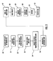
- Figure 2 is a flow diagram of the method for manufacturing a header assembly.
- a header assembly formed in accordance with an embodiment of the invention is illustrated in Figure 1 and shown generally at reference numeral 10.
- the current invention utilizes an entirely new manufacturing technology to completely eliminate the need for DMWs in header assemblies.
- the manufacturing method employs functionally graded compositional controls produced via powder metallurgy & hot isostatic processing (PM/HIP) to produce a smooth compositional transition from a stub tube alloy to a boiler tube alloy.
- PM/HIP powder metallurgy & hot isostatic processing
- the entire header assembly 10 is manufactured using PM/HIP including the stub tubes 12.
- the novelty of the approach is that the final 1-2 inches of the tube 12 are produced with a functionally graded composition such that the composition gradually changes from a low alloy steel (or CSEF steel) section 13 to an austenitic stainless steel section 15 using a transition section 14 which is formed by a series of incrementally applied steel powders from an atomized low alloy steel powder to an atomized austenitic steel powder.
- a transition section 14 which is formed by a series of incrementally applied steel powders from an atomized low alloy steel powder to an atomized austenitic steel powder.
- This is accomplished through utilization of a PM compositional controls to gradually transition the alloy from the lower Cr (2-1 /4Cr or 9Cr) to the 18Cr austenitic stainless steel boiler tube alloy.
- Use of the process eliminates the DMW that is normally required for joining the header tube assembly to the boiler tube.
- the HIP/PM technology eliminates the rolled & welded or extrusion manufacturing steps as a header section can be produced as one completed system. More importantly, it eliminates the joining of the stub tube 12 to the header 11 as the stub tube 12 and header 11 are integrally manufactured in one continuous PM/HIP process. Most importantly, the dissimilar metal weld (DMW) traditionally performed in the field is eliminated by grading the composition in the stub tube 12 from the low- Chromium alloy steel or CSEF steel to an 18wt%Cr stainless steel which can be welded to the stainless superheater tubing after installation.
- DMW dissimilar metal weld
- the process involves design of an exact duplicate of the a header section, Block 20, including the full tube sections, Figure 1 , beyond the typical DMW joint which can be obtained from drawings of the header.
- a reverse mold (container) of the header section is generated, Block 21, in two halves (or more) from a carbon steel material that establishes the final shape of the header section.
- the mold is assembled together and then filled with an atomized low alloy steel powder to fill the mold, Block 22.
- Composition of the stub tubes is graded by filling with successive layers of decreasing chromium content alloy from an 18%wtCr stainless steel to the 9% or 2 1 ⁇ 4%Cr ferritic steel, Block 22.
- the mold is evacuated using a vacuum to eliminate any potential air pockets and then sealed via welding, Block 23.
- the entire assembly is then inserted into a HIP furnace and brought to a high temperature and pressure (usually under an inert argon atmosphere) to consolidate and sinter the powder into the final shape of the header, Block 24.
- the assembly is maintained at the sintering temperature for a given period of time, Block 26, and then allowed to cool to room temperature, Block 27. Additional heat treatment will likely be required to bring the header to a normalized and tempered condition for service, Block 28. This final heat treatment can be performed in or out of the can. Removal of the can is required once the header has been allowed to return to room temperature, Block 29.
- the header should be in a near-net shape (near final shape) condition.
- Some clean-up and grinding may be required to assure that the can, mold and any residuals are removed to obtain a final surface, Block 30.
- a couple of additional steps are also required at this point: (1) boring of the stub tubes to produce an inner penetration, Block 31, and (2) chamfering of the inside diameter of the bore regions, Block 32. Both of these operations are easily accomplished using CNC milling/boring operations.
- the stub tubes are now an integral part of the header that requires no weld transition between the header and stub tube, a region of considerable problems in the past. Elimination of the weldment, removes thermal expansion concerns, potential fatigue and creep damage issues, and wedging that is often associated with the weld attachment of a stub tube. As an integral stub tube, only welds to attach the stub tube to the existing boiler tubes are required, significantly reducing future damage. Because the shape can be carefully controlled, repeatable smooth transitions between the stub and header are achieved reducing the potential for stress risers. Most importantly, the end of the stub tubes is the same stainless steel composition as the superheater it will be joined to in the field. By functionally grading the composition via the powder metallurgy method, the DMW joint is eliminated.
Landscapes
- Engineering & Computer Science (AREA)
- Mechanical Engineering (AREA)
- Manufacturing & Machinery (AREA)
- Chemical & Material Sciences (AREA)
- Composite Materials (AREA)
- Materials Engineering (AREA)
- Physics & Mathematics (AREA)
- Thermal Sciences (AREA)
- General Engineering & Computer Science (AREA)
- Powder Metallurgy (AREA)
- Arc Welding In General (AREA)
- Butt Welding And Welding Of Specific Article (AREA)
Claims (12)
- Procédé de fabrication d'un ensemble collecteur comportant une section de collecteur et une section de tube pour utilisation dans le raccordement de métaux dissemblables entre un tube de chaudière et l'ensemble collecteur, comprenant les étapes consistant à :(a) se procurer un moule inverse de l'ensemble collecteur ;(b) former la section de collecteur en remplissant une section de collecteur du moule inverse avec une poudre atomisée d'acier faiblement allié ;(c) former la section de tube :(i) en remplissant une première partie d'une section de tube du moule inverse avec une poudre atomisée d'acier faiblement allié ;(ii) en formant une région de transition en remplissant une deuxième partie de la section de tube du moule inverse avec une série de poudres d'acier atomisées par incréments depuis un acier faiblement allié jusqu'à un acier inoxydable austénitique ;(iii) en remplissant une troisième partie de la section de tube du moule inverse avec une poudre atomisée d'acier inoxydable austénitique, la région de transition étant disposée entre la première partie et la troisième partie de telle sorte que la poudre d'acier faiblement allié de la région de transition soit placée à côté de la poudre d'acier faiblement allié de la première partie et la poudre d'acier inoxydable austénitique de la région de transition soit placée à côté de la troisième partie ; et(d) consolider et faire fondre les poudres atomisées dans une atmosphère à haute température et haute pression pour former l'ensemble collecteur.
- Procédé selon la revendication 1, dans lequel l'étape de consolidation et de fusion se déroule dans une atmosphère gazeuse inerte.
- Procédé selon la revendication 1, comprenant en outre l'étape consistant à soumettre le moule à un vide pour éliminer les poches d'air.
- Procédé selon la revendication 3, comprenant en outre l'étape consistant à sceller le moule pour maintenir le vide.
- Procédé selon la revendication 1, comprenant en outre l'étape consistant à refroidir le moule et les poudres consolidées à la température ambiante.
- Procédé selon la revendication 1, comprenant en outre l'étape consistant à traiter thermiquement l'ensemble collecteur.
- Procédé selon la revendication 1, comprenant en outre l'étape consistant à finir l'ensemble collecteur en une forme finals :(a) en meulant la surface externe de l'ensemble collecteur pour retirer tous les résidus ;(b) en alésant la section de tube de l'ensemble collecteur pour créer une pénétration interne ; et(c) en chanfreinant l'intérieur de la section de tube alésée.
- Procédé selon la revendication 1, comprenant en outre l'étape consistant à insérer le moule et les poudres atomisées dans un four de traitement isostatique à chaud pour consolider et faire fondre les poudres atomisées.
- Ensemble collecteur pour utilisation dans le raccordement d'une tuyauterie en acier faiblement allié et de tubes en acier inoxydable austénitique, comprenant :(a) une section de collecteur constituée d'un acier faiblement allié ; et(b) une section de tube s'étendant vers l'extérieur depuis la section de collecteur comportant :(i) une première section en acier faiblement allié raccordée à la section de collecteur ;(ii) une deuxième section de transition ; et(iii) une troisième section en acier inoxydable austénitique pour raccordement aux tubes en acier inoxydable austénitique, la deuxième section de transition étant disposée entre la première section en acier faiblement allié et la troisième section en acier inoxydable austénitique.
- Ensemble collecteur selon la revendication 9, dans lequel la section de tube est formée d'une seule pièce avec la section de collecteur.
- Ensemble collecteur selon la revendication 9, dans lequel la deuxième section de transition est constituée d'une série d'aciers appliqués par incréments en partant d'un acier faiblement allié pour couplage avec la première section en acier allié et en augmentant progressivement la teneur en chrome jusqu'à un acier inoxydable austénitique pour couplage avec la troisième section en acier inoxydable austénitique.
- Ensemble collecteur selon la revendication 9, dans lequel la première section en acier allié, la deuxième section de transition et la troisième section en acier inoxydable austénitique forment une section de tube sans soudure.
Applications Claiming Priority (2)
| Application Number | Priority Date | Filing Date | Title |
|---|---|---|---|
| US201161489507P | 2011-05-24 | 2011-05-24 | |
| US13/463,587 US20120299288A1 (en) | 2011-05-24 | 2012-05-03 | FUNCTIONALLY GRADED COMPOSITIONAL CONTROL METHODS TO ELIMINATE DISSIMILAR METAL WELDS (DMWs) DURING MANUFACTURE OF INTEGRAL HEADERS |
Publications (2)
| Publication Number | Publication Date |
|---|---|
| EP2527063A1 EP2527063A1 (fr) | 2012-11-28 |
| EP2527063B1 true EP2527063B1 (fr) | 2013-07-24 |
Family
ID=46087548
Family Applications (1)
| Application Number | Title | Priority Date | Filing Date |
|---|---|---|---|
| EP12168167.0A Not-in-force EP2527063B1 (fr) | 2011-05-24 | 2012-05-16 | Procédés de commande de composition à gradient fonctionnel pour éliminer les soudures métalliques dissemblables (DMWs) pendant la fabrication d'en-têtes intégraux |
Country Status (4)
| Country | Link |
|---|---|
| US (1) | US20120299288A1 (fr) |
| EP (1) | EP2527063B1 (fr) |
| JP (1) | JP2013028862A (fr) |
| CN (1) | CN102962463A (fr) |
Families Citing this family (3)
| Publication number | Priority date | Publication date | Assignee | Title |
|---|---|---|---|---|
| JP5320010B2 (ja) * | 2008-10-07 | 2013-10-23 | 三菱重工業株式会社 | 管寄せ管台の溶接構造 |
| CN103481005B (zh) * | 2013-08-21 | 2015-03-25 | 杭州电子科技大学 | 一种管道径向螺栓焊接对中辅助机构 |
| EP3064307A1 (fr) * | 2015-03-05 | 2016-09-07 | Laborelec CVBA | Système et méthode d'assemblage par soudage par friction d'un premier élément en acier et d'un deuxième élément en acier en utilisant un adaptateur en alliages à base de Ni |
Family Cites Families (3)
| Publication number | Priority date | Publication date | Assignee | Title |
|---|---|---|---|---|
| ES2001332A6 (es) * | 1985-07-02 | 1988-05-16 | Framatome Sa | Generador de vapor |
| JP2001214231A (ja) * | 2000-01-31 | 2001-08-07 | Kubota Corp | 高温ガス炉の熱交換用チューブおよびその製造方法 |
| US6708651B1 (en) * | 2003-05-05 | 2004-03-23 | Babcock & Wilcox Canada Ltd. | Feedwater apparatus |
-
2012
- 2012-05-03 US US13/463,587 patent/US20120299288A1/en not_active Abandoned
- 2012-05-16 EP EP12168167.0A patent/EP2527063B1/fr not_active Not-in-force
- 2012-05-17 JP JP2012113316A patent/JP2013028862A/ja active Pending
- 2012-05-24 CN CN2012101634575A patent/CN102962463A/zh active Pending
Also Published As
| Publication number | Publication date |
|---|---|
| EP2527063A1 (fr) | 2012-11-28 |
| US20120299288A1 (en) | 2012-11-29 |
| JP2013028862A (ja) | 2013-02-07 |
| CN102962463A (zh) | 2013-03-13 |
Similar Documents
| Publication | Publication Date | Title |
|---|---|---|
| US11292078B2 (en) | System for and method of linking by friction welding a first piece of steel to a second piece of steel with use of Ni-based alloys adapter | |
| CN103433636B (zh) | 压焊复合法制造双金属冶金复合管的方法 | |
| CN102031995B (zh) | 多合金涡轮机转子段、焊接涡轮机转子及其制造方法 | |
| EP2527064A1 (fr) | Procédé de fabrication d'appareil sans soudure pour connexion de métaux dissemblables au moyen de commande de métallurgie des poudres à commande compositionnelle à gradient fonctionnel et procédés de traitement isostatique à chaud | |
| EP2901023B1 (fr) | Brasage fort par aluminium de pales de soufflante creuses en titane | |
| Kannan et al. | Optimization of friction welding by taguchi and ANOVA method on commercial aluminium tube to Al 2025 tube plate with backing block using an external tool | |
| US20090057287A1 (en) | Method and apparatus related to joining dissimilar metal | |
| EP2527063A1 (fr) | Procédés de commande de composition à gradient fonctionnel pour éliminer les soudures métalliques dissemblables (dmws) pendant la fabrication d'en-têtes intégraux | |
| US11738404B2 (en) | Method to eliminate dissimilar metal welds | |
| US20120301344A1 (en) | Method of using powder metallurgy fabrication for manufacturing integral header and tube replacement sections | |
| US8322595B2 (en) | Joining method and resultant article | |
| EP2284361A2 (fr) | Développements relatifs aux rotors à tambour | |
| KR20120131124A (ko) | 일체형 헤더의 제조 동안 이종 금속 용접부(DMWs)를 제거하기 위한 기능적으로 분류된 조성 제어 방법 | |
| JPH058057A (ja) | 二重金属管の製造方法 | |
| JPH029544B2 (fr) | ||
| JP2001214231A (ja) | 高温ガス炉の熱交換用チューブおよびその製造方法 | |
| KR20120131123A (ko) | 일체형 헤더 및 튜브 교체 섹션을 제조하기 위해 분말 야금술을 이용하는 방법 | |
| JPH029543B2 (fr) | ||
| JPS6076292A (ja) | クラツド鋼管の製造方法 | |
| JPS6076291A (ja) | クラツド鋼管の製造方法 |
Legal Events
| Date | Code | Title | Description |
|---|---|---|---|
| PUAI | Public reference made under article 153(3) epc to a published international application that has entered the european phase |
Free format text: ORIGINAL CODE: 0009012 |
|
| AK | Designated contracting states |
Kind code of ref document: A1 Designated state(s): AL AT BE BG CH CY CZ DE DK EE ES FI FR GB GR HR HU IE IS IT LI LT LU LV MC MK MT NL NO PL PT RO RS SE SI SK SM TR |
|
| AX | Request for extension of the european patent |
Extension state: BA ME |
|
| 17P | Request for examination filed |
Effective date: 20130108 |
|
| GRAP | Despatch of communication of intention to grant a patent |
Free format text: ORIGINAL CODE: EPIDOSNIGR1 |
|
| RIC1 | Information provided on ipc code assigned before grant |
Ipc: B22F 5/12 20060101ALI20130228BHEP Ipc: B22F 3/15 20060101AFI20130228BHEP Ipc: B22F 7/06 20060101ALI20130228BHEP Ipc: F22B 37/22 20060101ALI20130228BHEP |
|
| GRAS | Grant fee paid |
Free format text: ORIGINAL CODE: EPIDOSNIGR3 |
|
| GRAA | (expected) grant |
Free format text: ORIGINAL CODE: 0009210 |
|
| AK | Designated contracting states |
Kind code of ref document: B1 Designated state(s): AL AT BE BG CH CY CZ DE DK EE ES FI FR GB GR HR HU IE IS IT LI LT LU LV MC MK MT NL NO PL PT RO RS SE SI SK SM TR |
|
| REG | Reference to a national code |
Ref country code: GB Ref legal event code: FG4D |
|
| REG | Reference to a national code |
Ref country code: CH Ref legal event code: EP |
|
| REG | Reference to a national code |
Ref country code: AT Ref legal event code: REF Ref document number: 623101 Country of ref document: AT Kind code of ref document: T Effective date: 20130815 |
|
| REG | Reference to a national code |
Ref country code: IE Ref legal event code: FG4D |
|
| REG | Reference to a national code |
Ref country code: DE Ref legal event code: R096 Ref document number: 602012000157 Country of ref document: DE Effective date: 20130919 |
|
| REG | Reference to a national code |
Ref country code: AT Ref legal event code: MK05 Ref document number: 623101 Country of ref document: AT Kind code of ref document: T Effective date: 20130724 |
|
| REG | Reference to a national code |
Ref country code: NL Ref legal event code: VDEP Effective date: 20130724 |
|
| REG | Reference to a national code |
Ref country code: LT Ref legal event code: MG4D |
|
| PG25 | Lapsed in a contracting state [announced via postgrant information from national office to epo] |
Ref country code: IS Free format text: LAPSE BECAUSE OF FAILURE TO SUBMIT A TRANSLATION OF THE DESCRIPTION OR TO PAY THE FEE WITHIN THE PRESCRIBED TIME-LIMIT Effective date: 20131124 Ref country code: LT Free format text: LAPSE BECAUSE OF FAILURE TO SUBMIT A TRANSLATION OF THE DESCRIPTION OR TO PAY THE FEE WITHIN THE PRESCRIBED TIME-LIMIT Effective date: 20130724 Ref country code: AT Free format text: LAPSE BECAUSE OF FAILURE TO SUBMIT A TRANSLATION OF THE DESCRIPTION OR TO PAY THE FEE WITHIN THE PRESCRIBED TIME-LIMIT Effective date: 20130724 Ref country code: PT Free format text: LAPSE BECAUSE OF FAILURE TO SUBMIT A TRANSLATION OF THE DESCRIPTION OR TO PAY THE FEE WITHIN THE PRESCRIBED TIME-LIMIT Effective date: 20131125 Ref country code: SE Free format text: LAPSE BECAUSE OF FAILURE TO SUBMIT A TRANSLATION OF THE DESCRIPTION OR TO PAY THE FEE WITHIN THE PRESCRIBED TIME-LIMIT Effective date: 20130724 Ref country code: BE Free format text: LAPSE BECAUSE OF FAILURE TO SUBMIT A TRANSLATION OF THE DESCRIPTION OR TO PAY THE FEE WITHIN THE PRESCRIBED TIME-LIMIT Effective date: 20130724 Ref country code: HR Free format text: LAPSE BECAUSE OF FAILURE TO SUBMIT A TRANSLATION OF THE DESCRIPTION OR TO PAY THE FEE WITHIN THE PRESCRIBED TIME-LIMIT Effective date: 20130724 Ref country code: NO Free format text: LAPSE BECAUSE OF FAILURE TO SUBMIT A TRANSLATION OF THE DESCRIPTION OR TO PAY THE FEE WITHIN THE PRESCRIBED TIME-LIMIT Effective date: 20131024 Ref country code: CY Free format text: LAPSE BECAUSE OF FAILURE TO SUBMIT A TRANSLATION OF THE DESCRIPTION OR TO PAY THE FEE WITHIN THE PRESCRIBED TIME-LIMIT Effective date: 20130918 |
|
| PG25 | Lapsed in a contracting state [announced via postgrant information from national office to epo] |
Ref country code: PL Free format text: LAPSE BECAUSE OF FAILURE TO SUBMIT A TRANSLATION OF THE DESCRIPTION OR TO PAY THE FEE WITHIN THE PRESCRIBED TIME-LIMIT Effective date: 20130724 Ref country code: FI Free format text: LAPSE BECAUSE OF FAILURE TO SUBMIT A TRANSLATION OF THE DESCRIPTION OR TO PAY THE FEE WITHIN THE PRESCRIBED TIME-LIMIT Effective date: 20130724 Ref country code: NL Free format text: LAPSE BECAUSE OF FAILURE TO SUBMIT A TRANSLATION OF THE DESCRIPTION OR TO PAY THE FEE WITHIN THE PRESCRIBED TIME-LIMIT Effective date: 20130724 Ref country code: GR Free format text: LAPSE BECAUSE OF FAILURE TO SUBMIT A TRANSLATION OF THE DESCRIPTION OR TO PAY THE FEE WITHIN THE PRESCRIBED TIME-LIMIT Effective date: 20131025 Ref country code: LV Free format text: LAPSE BECAUSE OF FAILURE TO SUBMIT A TRANSLATION OF THE DESCRIPTION OR TO PAY THE FEE WITHIN THE PRESCRIBED TIME-LIMIT Effective date: 20130724 |
|
| PG25 | Lapsed in a contracting state [announced via postgrant information from national office to epo] |
Ref country code: CY Free format text: LAPSE BECAUSE OF FAILURE TO SUBMIT A TRANSLATION OF THE DESCRIPTION OR TO PAY THE FEE WITHIN THE PRESCRIBED TIME-LIMIT Effective date: 20130724 |
|
| PG25 | Lapsed in a contracting state [announced via postgrant information from national office to epo] |
Ref country code: EE Free format text: LAPSE BECAUSE OF FAILURE TO SUBMIT A TRANSLATION OF THE DESCRIPTION OR TO PAY THE FEE WITHIN THE PRESCRIBED TIME-LIMIT Effective date: 20130724 Ref country code: RO Free format text: LAPSE BECAUSE OF FAILURE TO SUBMIT A TRANSLATION OF THE DESCRIPTION OR TO PAY THE FEE WITHIN THE PRESCRIBED TIME-LIMIT Effective date: 20130724 Ref country code: CZ Free format text: LAPSE BECAUSE OF FAILURE TO SUBMIT A TRANSLATION OF THE DESCRIPTION OR TO PAY THE FEE WITHIN THE PRESCRIBED TIME-LIMIT Effective date: 20130724 Ref country code: SK Free format text: LAPSE BECAUSE OF FAILURE TO SUBMIT A TRANSLATION OF THE DESCRIPTION OR TO PAY THE FEE WITHIN THE PRESCRIBED TIME-LIMIT Effective date: 20130724 Ref country code: DK Free format text: LAPSE BECAUSE OF FAILURE TO SUBMIT A TRANSLATION OF THE DESCRIPTION OR TO PAY THE FEE WITHIN THE PRESCRIBED TIME-LIMIT Effective date: 20130724 |
|
| PG25 | Lapsed in a contracting state [announced via postgrant information from national office to epo] |
Ref country code: IT Free format text: LAPSE BECAUSE OF FAILURE TO SUBMIT A TRANSLATION OF THE DESCRIPTION OR TO PAY THE FEE WITHIN THE PRESCRIBED TIME-LIMIT Effective date: 20130724 Ref country code: ES Free format text: LAPSE BECAUSE OF FAILURE TO SUBMIT A TRANSLATION OF THE DESCRIPTION OR TO PAY THE FEE WITHIN THE PRESCRIBED TIME-LIMIT Effective date: 20130724 |
|
| PLBE | No opposition filed within time limit |
Free format text: ORIGINAL CODE: 0009261 |
|
| STAA | Information on the status of an ep patent application or granted ep patent |
Free format text: STATUS: NO OPPOSITION FILED WITHIN TIME LIMIT |
|
| 26N | No opposition filed |
Effective date: 20140425 |
|
| REG | Reference to a national code |
Ref country code: DE Ref legal event code: R097 Ref document number: 602012000157 Country of ref document: DE Effective date: 20140425 |
|
| REG | Reference to a national code |
Ref country code: DE Ref legal event code: R119 Ref document number: 602012000157 Country of ref document: DE |
|
| PG25 | Lapsed in a contracting state [announced via postgrant information from national office to epo] |
Ref country code: LU Free format text: LAPSE BECAUSE OF FAILURE TO SUBMIT A TRANSLATION OF THE DESCRIPTION OR TO PAY THE FEE WITHIN THE PRESCRIBED TIME-LIMIT Effective date: 20140516 |
|
| PG25 | Lapsed in a contracting state [announced via postgrant information from national office to epo] |
Ref country code: MC Free format text: LAPSE BECAUSE OF FAILURE TO SUBMIT A TRANSLATION OF THE DESCRIPTION OR TO PAY THE FEE WITHIN THE PRESCRIBED TIME-LIMIT Effective date: 20130724 |
|
| REG | Reference to a national code |
Ref country code: DE Ref legal event code: R119 Ref document number: 602012000157 Country of ref document: DE Effective date: 20141202 |
|
| REG | Reference to a national code |
Ref country code: IE Ref legal event code: MM4A |
|
| REG | Reference to a national code |
Ref country code: FR Ref legal event code: ST Effective date: 20150130 |
|
| PG25 | Lapsed in a contracting state [announced via postgrant information from national office to epo] |
Ref country code: IE Free format text: LAPSE BECAUSE OF NON-PAYMENT OF DUE FEES Effective date: 20140516 Ref country code: DE Free format text: LAPSE BECAUSE OF NON-PAYMENT OF DUE FEES Effective date: 20141202 |
|
| PG25 | Lapsed in a contracting state [announced via postgrant information from national office to epo] |
Ref country code: FR Free format text: LAPSE BECAUSE OF NON-PAYMENT OF DUE FEES Effective date: 20140602 |
|
| REG | Reference to a national code |
Ref country code: CH Ref legal event code: PL |
|
| PG25 | Lapsed in a contracting state [announced via postgrant information from national office to epo] |
Ref country code: LI Free format text: LAPSE BECAUSE OF NON-PAYMENT OF DUE FEES Effective date: 20150531 Ref country code: CH Free format text: LAPSE BECAUSE OF NON-PAYMENT OF DUE FEES Effective date: 20150531 |
|
| PG25 | Lapsed in a contracting state [announced via postgrant information from national office to epo] |
Ref country code: MT Free format text: LAPSE BECAUSE OF FAILURE TO SUBMIT A TRANSLATION OF THE DESCRIPTION OR TO PAY THE FEE WITHIN THE PRESCRIBED TIME-LIMIT Effective date: 20130724 |
|
| PG25 | Lapsed in a contracting state [announced via postgrant information from national office to epo] |
Ref country code: SM Free format text: LAPSE BECAUSE OF FAILURE TO SUBMIT A TRANSLATION OF THE DESCRIPTION OR TO PAY THE FEE WITHIN THE PRESCRIBED TIME-LIMIT Effective date: 20130724 |
|
| PG25 | Lapsed in a contracting state [announced via postgrant information from national office to epo] |
Ref country code: BG Free format text: LAPSE BECAUSE OF FAILURE TO SUBMIT A TRANSLATION OF THE DESCRIPTION OR TO PAY THE FEE WITHIN THE PRESCRIBED TIME-LIMIT Effective date: 20130724 Ref country code: RS Free format text: LAPSE BECAUSE OF NON-PAYMENT OF DUE FEES Effective date: 20130724 |
|
| PG25 | Lapsed in a contracting state [announced via postgrant information from national office to epo] |
Ref country code: TR Free format text: LAPSE BECAUSE OF FAILURE TO SUBMIT A TRANSLATION OF THE DESCRIPTION OR TO PAY THE FEE WITHIN THE PRESCRIBED TIME-LIMIT Effective date: 20130724 Ref country code: SI Free format text: LAPSE BECAUSE OF FAILURE TO SUBMIT A TRANSLATION OF THE DESCRIPTION OR TO PAY THE FEE WITHIN THE PRESCRIBED TIME-LIMIT Effective date: 20130724 Ref country code: HU Free format text: LAPSE BECAUSE OF FAILURE TO SUBMIT A TRANSLATION OF THE DESCRIPTION OR TO PAY THE FEE WITHIN THE PRESCRIBED TIME-LIMIT; INVALID AB INITIO Effective date: 20120516 |
|
| GBPC | Gb: european patent ceased through non-payment of renewal fee |
Effective date: 20160516 |
|
| PG25 | Lapsed in a contracting state [announced via postgrant information from national office to epo] |
Ref country code: GB Free format text: LAPSE BECAUSE OF NON-PAYMENT OF DUE FEES Effective date: 20160516 |
|
| PG25 | Lapsed in a contracting state [announced via postgrant information from national office to epo] |
Ref country code: MK Free format text: LAPSE BECAUSE OF FAILURE TO SUBMIT A TRANSLATION OF THE DESCRIPTION OR TO PAY THE FEE WITHIN THE PRESCRIBED TIME-LIMIT Effective date: 20130724 |
|
| PG25 | Lapsed in a contracting state [announced via postgrant information from national office to epo] |
Ref country code: AL Free format text: LAPSE BECAUSE OF FAILURE TO SUBMIT A TRANSLATION OF THE DESCRIPTION OR TO PAY THE FEE WITHIN THE PRESCRIBED TIME-LIMIT Effective date: 20130724 |