EP2527083B1 - Procédé pour l'usinage des faces frontales de pièces de bois, de plastique ou d'un matériau similaire - Google Patents
Procédé pour l'usinage des faces frontales de pièces de bois, de plastique ou d'un matériau similaire Download PDFInfo
- Publication number
- EP2527083B1 EP2527083B1 EP12002500.2A EP12002500A EP2527083B1 EP 2527083 B1 EP2527083 B1 EP 2527083B1 EP 12002500 A EP12002500 A EP 12002500A EP 2527083 B1 EP2527083 B1 EP 2527083B1
- Authority
- EP
- European Patent Office
- Prior art keywords
- workpieces
- tool
- workpiece
- clamping
- clamped
- Prior art date
- Legal status (The legal status is an assumption and is not a legal conclusion. Google has not performed a legal analysis and makes no representation as to the accuracy of the status listed.)
- Not-in-force
Links
- 238000000034 method Methods 0.000 title claims description 32
- 239000002023 wood Substances 0.000 title claims description 5
- 239000000463 material Substances 0.000 title description 4
- 238000003801 milling Methods 0.000 claims description 29
- 238000003754 machining Methods 0.000 claims description 22
- 210000000078 claw Anatomy 0.000 description 22
- 238000004519 manufacturing process Methods 0.000 description 4
- 238000005520 cutting process Methods 0.000 description 3
- 238000005096 rolling process Methods 0.000 description 3
- 230000000903 blocking effect Effects 0.000 description 2
- 238000010276 construction Methods 0.000 description 2
- 239000006228 supernatant Substances 0.000 description 2
- 230000001360 synchronised effect Effects 0.000 description 2
- 244000229769 Chlorophora excelsa Species 0.000 description 1
- 235000004607 Chlorophora excelsa Nutrition 0.000 description 1
- 241000196324 Embryophyta Species 0.000 description 1
- 240000007817 Olea europaea Species 0.000 description 1
- 230000004913 activation Effects 0.000 description 1
- 239000007799 cork Substances 0.000 description 1
- 230000000694 effects Effects 0.000 description 1
- 210000000887 face Anatomy 0.000 description 1
- 230000002349 favourable effect Effects 0.000 description 1
- 210000001061 forehead Anatomy 0.000 description 1
- 238000007654 immersion Methods 0.000 description 1
- 230000001105 regulatory effect Effects 0.000 description 1
- 239000002699 waste material Substances 0.000 description 1
Images




Classifications
-
- B—PERFORMING OPERATIONS; TRANSPORTING
- B27—WORKING OR PRESERVING WOOD OR SIMILAR MATERIAL; NAILING OR STAPLING MACHINES IN GENERAL
- B27G—ACCESSORY MACHINES OR APPARATUS FOR WORKING WOOD OR SIMILAR MATERIALS; TOOLS FOR WORKING WOOD OR SIMILAR MATERIALS; SAFETY DEVICES FOR WOOD WORKING MACHINES OR TOOLS
- B27G19/00—Safety guards or devices specially adapted for wood saws; Auxiliary devices facilitating proper operation of wood saws
- B27G19/10—Measures preventing splintering of sawn portions of wood
-
- B—PERFORMING OPERATIONS; TRANSPORTING
- B27—WORKING OR PRESERVING WOOD OR SIMILAR MATERIAL; NAILING OR STAPLING MACHINES IN GENERAL
- B27F—DOVETAILED WORK; TENONS; SLOTTING MACHINES FOR WOOD OR SIMILAR MATERIAL; NAILING OR STAPLING MACHINES
- B27F1/00—Dovetailed work; Tenons; Making tongues or grooves; Groove- and- tongue jointed work; Finger- joints
- B27F1/02—Making tongues or grooves, of indefinite length
- B27F1/04—Making tongues or grooves, of indefinite length along only one edge of a board
Definitions
- the invention relates to a method for machining the end faces of workpieces made of wood, plastic and the like according to the preamble of claim 1.
- the invention has the object of providing the generic method in such a way that an end-side machining of the workpieces with high production capacity, low cost, in a compact machine and device construction and without or with minimal tears can be easily performed.
- the workpieces are clamped in their longitudinal direction offset from one another and then machined frontally with the milling tool. Due to the staggered clamping, the workpieces can be processed optimally on the front side.
- the milling tool is here weg- and time-optimized procedure so that with him first the one end face of a workpiece and then subsequently the longitudinally offset end face of the adjacent workpiece are processed. In this way, a simple, time-saving and reliable face machining of the workpieces is ensured.
- the workpieces are machined by the milling tool in synchronism.
- chipping of the workpiece at the outlet of the milling tool is reliably prevented.
- the front sides of the workpieces can be processed at the entrance of the milling tool with a rolling start-up strategy, which also in this case the chipping is minimized. The chipping is thus avoided or minimized on both workpieces.
- the distance between the workpieces is advantageously about as large as half the circle diameter of the milling tool.
- the workpieces can be arranged side by side with a relatively small distance, thereby reducing the processing time of both workpieces and thus the production capacity is increased.
- the longitudinal offset between the two workpieces also corresponds to about half the circle diameter of the milling tool.
- the milling tool is moved in a movement path around the workpieces. Then all faces of the two workpieces can be processed in one go.
- clamping device workpieces 1 can be clamped for machining.
- two workpieces 1 can be clamped simultaneously with the clamping device ( Fig. 4 and 6 ).
- the clamping device is clamped by means of clamping devices 2 on a bracket 3.
- the bracket 3 has on its longitudinal sides clamping profiles 4, 5 ( Fig. 2 ), with which the clamping devices 2 interact.
- the Clamping devices 2 each have two spaced adjacent clamping fingers 6, which engage under the clamping profiles 4, 5 of the console 3. The position of the clamping device along the console 3 is set exactly (not shown) setting aids.
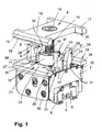
- the tensioning device has a housing 7, in which a drive for a tensioning element 8 designed as clamping element and stops 9, 9 ', 9 ", 9'" for the workpieces 1 are housed.
- the clamping claw 8 is mounted on the upper end of a threaded spindle 10, which in turn is received in a piston 11. It is housed in a (not shown) cylinder tube which is arranged in the housing 7.
- the piston 11 projects upwards out of the housing 7.
- the protruding end of the piston 11 is guided axially in a guide ring 12 connected to the housing 7.
- the clamping claw 8 With the threaded spindle 10, the clamping claw 8 can be adjusted to the height of the workpiece 1 to be machined by the clamping claw 8 is rotated together with the threaded spindle 10 in each 360 ° steps.
- the threaded spindle 10 moves in this adjustment of the clamping claw 8 to the workpiece height in the axial direction relative to the piston 11.
- a locking pin In the guide ring 12, a locking pin is arranged, which can be actuated with a handle 13. In a blocking position it engages through a slot at the upper end of the piston 11 in an axially extending groove 14 of the threaded spindle 10 a.
- the locking pin prevents rotation of the piston 11 and the threaded spindle 10 in the locking position.
- the threaded spindle 10 can be rotated with the aid of the clamping claw 8 , This results in a rough adjustment of the clamping claw 8 on the height or thickness of the workpiece 1. Subsequently, the locking pin is pushed back into its blocking position and the piston 11 is pressurized with pressure medium when the workpiece 1 is to be clamped.
- the piston 11 is preferably pneumatically operated, but can also be acted upon by hydraulic medium.
- the clamping claw 8 is fixed with a central screw 15 on the threaded spindle 10.
- the clamping claw 8 has a double T-shape with two narrow, mutually parallel webs 16, 17 and a web connecting these webs 18.
- On the underside of the webs 16, 17 are support strips 19, 20 attached, extending over the length of the webs 16, 17 extend and with which the clamping claw 8 rests on the workpieces 1.
- the support strips 19, 20 may be made of a softer material, such as rubber, plastic, cork or the like, so that during clamping the workpiece surface is not damaged.
- each other two workpiece supports 21, 22 are provided with respect to the threaded spindle 10. They protrude in the longitudinal direction and also transversely to their longitudinal direction on the housing 7. This is despite a compact design of the clamping device, a large support surface for supporting the workpieces 1 available.
- the two workpiece supports 21, 22 are the same design, but arranged mirror-symmetrically to each other. They each have T-shaped outline. With the foot 23, 24, the workpiece supports 21, 22 are mounted on the housing 7. The webs 25, 26 of the workpiece supports 21, 22 project in the longitudinal direction and in the transverse direction over the housing 7.
- the workpiece supports 21, 22 are the webs 16, 17 of the clamping claw 8 against. Perpendicular to the workpiece supports 21, 22, the stops 9, 9 ', 9 ", 9'” slidably disposed. In each case two stops 9, 9 'and 9 ", 9'” are diametrically opposite each other with respect to the threaded spindle 10. They stand up in the direction of the clamping claw 8 on the workpiece supports 21, 22 before and are in the range between the protruding ends of the webs 25, 26 of the workpiece supports 21, 22 and between the webs 16, 17 of the clamping claw 8. Thus, the clamping claw 8 with its center 18 when performing the Spannhubes drive between the attacks.
- the stops 9 ", 9 '” sit with corresponding spindle nuts on the drive spindle. So that the stops 9 ", 9 '" synchronously moved in opposite directions to each other, the drive spindle has left- and right-hand threaded sections on which the spindle nuts sit.
- the spindle nuts are provided at the lower end of narrow beams 27 which extend upwardly slightly above the workpiece supports 21, 22.
- To the carrier 27 close stop pieces 28, which are provided on their sides facing away from each other with a flat stop surface 29 on which the workpieces 1 can rest.
- the carrier 27 and the stopper pieces 28 may be formed integrally with each other;
- the spindle nut can also be directly integrated as a thread in it.
- the stop surfaces 29 go at the lower end over a shoulder surface 30, which is advantageously at a small distance in the region above the workpiece supports 21, 22, at right angles in an outer side 31 of the carrier 27 via.
- the stops 9, 9 ', 9 ", 9'” are thus provided on their sides facing away from each other with a paragraph. This makes it possible that the stops 9, 9 ', 9 ", 9”' can be moved so far that the stop surfaces 29 in the area above the workpiece supports 21, 22 are located.
- the mutually facing inner sides 32 of the stop pieces 28 extend converging in the direction of the carrier 27.
- the stop pieces 28 have characterized at the free end of their smallest width, which increases steadily in the direction of the carrier 27.
- stops 9, 9 ', 9 ", 9'” of the clamping direction are formed substantially the same.
- the opposing pairs of stops 9, 9 ", 9 ', 9'” are each arranged the same.
- the clamping device can be clamped to the console 3 at any required location in the manner described with the clamping devices 2.
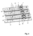
- Fig. 3 shows by way of example that a plurality of consoles 3 can be provided lying side by side in parallel. In the embodiment, three consoles are provided, however, the number of consoles may also be smaller or larger.
- a clamping device is clamped on each console. Several consoles are used when longer workpieces 1 are to be clamped. It is advantageous if between adjacent brackets 3 each a support aid 33 is provided on which the workpieces 1 can be additionally supported in the area between adjacent brackets 3 in the supply to the clamping device.
- the support aids 33 are how Fig. 2 shows, by way of example with two cylinders 34 adjustable in height. Shown are double cylinder, with which the support aids 33 can take three defined height positions.
- the illustrated first position is the basic position in lowered position after the workpieces 1 are clamped in the clamping device. In this lowered position, the workpieces 1 are freely accessible for processing with the respective tool.
- the second position is approached when only one piston of the double cylinder, and the third, when both pistons of the double cylinder are extended.
- the top of the support means 33 is exactly in a plane with the workpiece supports 21, 22, so that the workpieces 1 can be easily pushed into the clamping device that they rest flat on the workpiece supports 21, 22 and at right angles to the attacks 9, 9 "or 9 ', 9'" rest.
- the second position represents an intermediate position, which is necessary if instead of the illustrated tensioning devices Saugspann- or vacuum clamping devices are used, which have lower height.
- Saugspann driversen are used to clamp, for example, sheet-like parts, such as door leaves.
- the support aids 33 are in this case slightly above the support surface of the Saugspann engaged before to deliver the workpieces 1 effortlessly to be able to. By the support means 33 ensures that the workpieces 1 can be optimally supported over its length.
- the support aids 33 are upstanding strips that can be used between adjacent brackets 3, even if they are only a short distance apart.
- the brackets 3 are advantageously on a machine frame or stand, not shown, transversely to its longitudinal direction in the direction of arrow 35 adjustable, so that the distance between the brackets can be adapted to the length of the workpieces 1 and their processing.
- longitudinal stops 36 In order to position the workpieces 1 for processing in their longitudinal direction, longitudinal stops 36 (FIGS. Fig. 3 ) are provided, against which the workpieces 1 with their front ends in the feed direction.
- the longitudinal stops 36 are retractable, so that the workpieces 1 can be processed on these end faces and can be further transported in the longitudinal direction after processing and release by the clamping devices.
- the longitudinal stops 36 may be arranged fixed to the machine or individually positioned by means of known adjusting devices, not shown.
- the clamping device can be processed at the same time preferably equal long and equal workpieces 1, which preferably have the same profile both on their front sides and their longitudinal sides.
- workpieces with the same machining profile are in windows (frame and sash) respectively the two upright and the two horizontal frame or wing parts.
- the stops 9, 9 'and 9 ", 9'" can be adjusted continuously, the workpieces 1 on the workpiece supports 21, 22 are each optimally positioned so clamped that an optimal processing is possible.
- the workpieces 1 can be positioned so that a sufficiently stable workpiece clamping and workpiece support is ensured, so that a high processing quality and precision is achieved.
- the clamping claw 8 can be adjusted over a sufficiently large height range, so that different high workpieces 1 can be clamped.
- the clamping claw 8 can be adjusted to a workpiece height of about 40 mm to about 110 mm.
- the activation of the drive shaft, with which the drive spindles for the stops 9, 9 ', 9 ", 9'" are actuated, is advantageously program-controlled. It is thereby possible to automatically adjust the clamping depth to the width of the workpieces 1 prior to the feeding of the workpieces 1 to be clamped and machined. This also makes it possible to pre-set the brackets 3 in the adjustment direction 35. Depending on the length of the clamped workpieces 1, a corresponding number of brackets 3 is used, wherein the distance from each other is additionally adjustable, preferably also programmatically.
- brackets 3 with the clamping devices are at a very small distance from one another.
- a very simple local processing on the top or bottom of the workpieces 1 is possible by the position of the brackets 3 and thus the clamping points are chosen so that the tools can perform the collision-free processing. For example, such operations are for window scantlings olive or Ecklagerbohrept.
- the support aids 33 which are advantageously located between the consoles 3, can also be programmatically positioned at the required height position before the workpieces 1 are fed.
- the clamping device is advantageous, seen in the longitudinal direction of the workpiece supports 21, 22, only so wide that even a short workpiece 1 clamped and can be edited without re-clamping both end faces of the workpiece.
- such short workpieces 1 have an exemplary length of only 180 mm.
- the two adjacent stops 9, 9 "and 9 ', 9'" can also create the short workpieces 1 in only one clamping device in exact alignment in its longitudinal axis on the attacks and tension. It is also possible to provide only a wider stop on each side on which the workpieces 1 can be clamped exactly as well.
- all clamping devices, the two oppositely positioned synchronously and consisting of two adjacent stops attacks groups 9, 9 'and 9 ", 9'" on.
- clamping device Since the clamping device is fixed by means of the clamping devices 2 on the brackets 3, it is possible in a simple manner, quickly remove the clamping device from the console 3 as needed and replace, for example, against a Saugspann coupled or another clamping device.
- stops are adjustable in the manner described, they can be very easily adjusted to different widths of workpieces 1, so that they can be optimally clamped and edited in a clamped position.
- the workpieces are intended for window parts, then these are individually planned with a window construction software, that is, part length, width, height, end-side and longitudinal profiling and bores.
- the Machine software calculates the resulting clamping positions and outputs the dimensions to be set for the brackets 3, the lateral stops 9, 9 ', 9 ", 9"' and the longitudinal stops 36.
- the positioning of the stops according to the calculated dimensions in a known manner with controlled or regulated positioning drives.
- the execution order, required tools and their trajectories are calculated and output with CNC coordinates.
- a method is described, with which the end faces of two workpieces 1, 1 'processed with a tool 37, in particular profiled.
- the two workpieces 1, 1 ' are mutually offset in the longitudinal direction by means of two clamping devices.
- two clamping devices are used, with their clamping claws 8, the workpieces are clamped in the manner described.
- other clamping devices can be used.
- the workpieces can also be clamped simultaneously and together only in a clamping device with a single clamping claw, which is correspondingly wide. In the method described below, only two clamping devices according to the Fig. 1 to 3 used.
- For longitudinal alignment serve the longitudinal stops 36, where the workpieces 1, 1 'come in the supply to the plant. Once the workpieces 1, 1 'are clamped, the longitudinal stops 36 are removed, preferably lowered. You then do not interfere with the frontal processing with the tool 37.
- FIG. 6 schematically the tool 37 and the movement or machining path is shown, which executes the tool 37 in the frontal machining of the workpieces 1, 1 '.
- both workpieces 1, 1' can be processed in one go through the tool 37.
- the end profiles produced on the end faces of the workpieces 1, 1 'by the milling tool 37 can be machined with a rolling start-up strategy in synchronism so that chipping of the wood upon entry of the milling tool 37 into the workpiece 1, 1' is avoided or at least minimized.
- the tool 37 is initially in the starting position I in the area next to the workpieces 1, 1 '.
- the direction of rotation of the tool 37 is indicated by an arrow.
- the tool 37 is first obliquely against the in Fig. 6 lower workpiece 1 'moves.
- the tool 37 seen in its axial direction, the workpiece 1 'touched (position II)
- the tool is moved along a curved path 38 whose radius corresponds approximately to the circle radius of the tool 37.
- a small chip removal on the longitudinal side of the workpiece 1 ' can already be done by the milling tool 37, which, however, must be less than the planned on this longitudinal side chip removal.
- the milling tool 37 just does not touch the workpiece 1 '.
- the theoretical contact point lies on the workpiece longitudinal side and in the workpiece longitudinal direction approximately in the plane of the maximum slot or transverse profile depth. However, it can be varied and optimized depending on the particular application and intended longitudinal and transverse profiling.
- the tool 37 is rotatably driven so that it works in synchronism. As a result, the tool can process the workpiece 1 'with only a low cutting pressure.
- This linear movement path 39 then returns to an oblique path of movement 40 when the tool 37 has reached position IV. In this position, the frontal machining of the workpiece 1 'is completed. In this case, the tool axis 48 is approximately in alignment with the workpiece longitudinal edge 49. Upon further movement of the tool 37, it emerges gradually from the workpiece 1. Since the end face of the workpiece 1 'is processed in synchronism, no chipping occurs when the tool exits the workpiece 1'.
- the tool would 37 after finishing the front side of the workpiece 1' already rest on the adjacent workpiece 1 or only a small distance (position IV) of him. The movement along the path 40 can then be almost eliminated.
- the tool 37 engages in the end face of the adjacent workpiece 1 and processes it this front side.
- the tool 37 engages the workpiece 1 with the required depth (position VI)
- the tool is displaced linearly along the path 42 which is perpendicular to the longitudinal axis of the workpiece 1.
- the machining of the front side of the workpiece 1 is carried out in synchronism.
- the tool 37 is moved until it has completely exited the workpiece 1 (position VII).
- the tool 37 is moved outside of the workpiece 1 to the opposite end face in the position VIII.
- the other end sides of the two workpieces 1, 1 ' are processed with it, wherein the movement paths are correspondingly reversed as in the previously described processing.
- the tool 37 is first brought along the oblique linear trajectory 43 to the workpiece 1. Once the position VIII is reached, the tool 37 is moved along the curved trajectory 44. This movement takes place when the tool 37 comes into contact with the workpiece 1. As soon as the tool 37 has reached its required immersion depth into the workpiece 1 (position IX), it is moved along the linear path 45, which runs perpendicular to the longitudinal axis of the workpiece 1 and parallel to the movement path 42.
- the tool 37 begins again to dive into the end face of the workpiece 1 '. Again, the workpiece moves along a curved path of movement 46, whose radius corresponds approximately to the circle radius of the tool. As soon as the tool 37 is immersed to the required extent in the end face of the workpiece 1 ', it is moved along the linear movement path 47, which runs parallel to the movement path 39, until the tool 37 has completely emerged from the workpiece 1' (position XI).
- the movement path sections 39, 42, 45, 47 of the milling tool 37 can also lie at any angle to the workpiece longitudinal axis.
- the frontal processing of the workpieces 1, 1 ' is always in synchronism. This reliably prevents chipping of the wood when entering and leaving the tool 37 from the workpieces 1, 1 'or minimized.
- the synchronous machining also means that it is possible to work on the end faces of the workpieces 1, 1 'with a relatively low cutting pressure. This procedure also has a favorable effect on the clamping force required for clamping the workpieces 1, 1 '. As a result of the synchronous machining, the end of the workpieces 1, 1 'projecting further beyond the clamping device is loaded such that it is pressed against the lateral stops 9, 9', 9 ", 9 '".
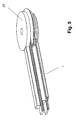
- Fig. 7 shows a clamping device
- the clamping claws 8 and workpiece supports 21, 22 are extended in the direction of the protruding end of the workpieces 1, 1 '.
- the projection of the workpieces 1, 1 'over the clamping claws 8 and workpiece supports 21, 22 is less than in the embodiment according to Fig. 6 .
- the workpieces 1, 1 ' are clamped in the same way as in the embodiment according to FIG Fig. 6 ,
- the processing of the ends of the two workpieces 1, 1 'takes place in the manner described.
- FIG. 6 A comparison of Fig. 6 and 7 shows that the workpieces 1, 1 'can be clamped in different positions.
- the clamping position according to Fig. 6 is the supernatant of the workpieces 1, 1 'on the clamping devices larger than in the clamping position Fig. 7 .
- this supernatant can be adjusted very easily.
- the two end faces of the two workpieces 1, 1 ' can be processed one after the other in one go, wherein a tool change is not necessary.
- the tool 37 is moved in the manner described around the workpieces 1, 1 'around.
- the movement of the tool 37 is preferably carried out programmatically. Compared to the total length of the workpieces 1, 1 'whose longitudinal offset in the inventive method is relatively low, so that only little additional space is required.
- the processing machine has only one spindle and if the workpieces 1, 1 'are to have different profiles on both end faces, then it will become smaller the machining of a front side of the workpieces 1, 1 'performed a tool change.
Landscapes
- Life Sciences & Earth Sciences (AREA)
- Engineering & Computer Science (AREA)
- Mechanical Engineering (AREA)
- Wood Science & Technology (AREA)
- Forests & Forestry (AREA)
- Jigs For Machine Tools (AREA)
Claims (8)
- Procédé d'usinage des faces avant de pièces en bois, en plastique ou similaire, dans lequel les faces avant des pièces sont usinées avec au moins un outil de fraisage entraîné en rotation, lesquelles sont serrées avec au moins un outil de serrage,
caractérisé en ce que deux pièces (1, 1') sont serrées avec un écart latéral et décalées entre elles dans leur sens longitudinal et usinées sur la face avant avec l'outil de fraisage (37). - Procédé selon la revendication 1,
caractérisé en ce que les faces avant des pièces (1, 1') sont usinées en sens direct. - Procédé selon la revendication 1 ou 2,
caractérisé en ce que l'écart latéral entre les pièces (1, 1') correspond à environ la moitié du diamètre de cercle de rotation de l'outil de fraisage (37). - Procédé selon l'une des revendications 1 à 3,
caractérisé en ce que le décalage longitudinal entre les deux pièces (1, 1') correspond à environ la moitié du diamètre de cercle de rotation de l'outil de fraisage (37). - Procédé selon l'une des revendications 1 à 4,
caractérisé en ce que pour usiner les deux faces avant des deux pièces (1, 1'), un seul outil de fraisage (37) est employé. - Procédé selon la revendication 5,
caractérisé en ce que l'outil de fraisage (37) est déplacé dans une trajectoire de mouvement (38 à 47) autour des pièces (1, 1'). - Procédé selon l'une des revendications 1 à 4,
caractérisé en ce que pour usiner les faces avant voisines des deux pièces (1, 1'), un outil de fraisage (37) respectif est employé. - Procédé selon l'une des revendications 1 à 7,
caractérisé en ce que les pièces (1, 1') sont positionnées à l'aide de butées longitudinales (36).
Applications Claiming Priority (1)
| Application Number | Priority Date | Filing Date | Title |
|---|---|---|---|
| DE201110102793 DE102011102793B3 (de) | 2011-05-27 | 2011-05-27 | Verfahren zur Bearbeitung der Stirnseiten von Werkstücken aus Holz, Kunststoff und dergleichen |
Publications (2)
| Publication Number | Publication Date |
|---|---|
| EP2527083A1 EP2527083A1 (fr) | 2012-11-28 |
| EP2527083B1 true EP2527083B1 (fr) | 2015-08-05 |
Family
ID=45977123
Family Applications (1)
| Application Number | Title | Priority Date | Filing Date |
|---|---|---|---|
| EP12002500.2A Not-in-force EP2527083B1 (fr) | 2011-05-27 | 2012-04-07 | Procédé pour l'usinage des faces frontales de pièces de bois, de plastique ou d'un matériau similaire |
Country Status (2)
| Country | Link |
|---|---|
| EP (1) | EP2527083B1 (fr) |
| DE (1) | DE102011102793B3 (fr) |
Family Cites Families (7)
| Publication number | Priority date | Publication date | Assignee | Title |
|---|---|---|---|---|
| DE3442466A1 (de) * | 1984-11-22 | 1986-05-28 | Planungs- und Ingenieursbüro Gisela Jurisch - Uhlenhaut, 2251 Hattstedtermarsch | Verfahren und vorrichtung zum herstellen von an beiden enden profilierten laenglichen holzgegenstaenden |
| DE3815101A1 (de) * | 1988-05-04 | 1989-11-16 | Wilhelm Hirsch Holzbearbeitung | Holzbearbeitungsmaschine |
| DE4107946A1 (de) * | 1991-03-13 | 1992-09-17 | Ludolf Stegherr | Verfahren und vorrichtung zum fraesen von werkstuecken aus holz oder holzaehnlichem material |
| DE19751246A1 (de) * | 1997-11-19 | 1999-05-20 | Wellein Eduard Dipl Kaufm | Verfahren und Vorrichtung zum stirnseitigen Fräsen eines Werkstückes |
| WO2004080649A1 (fr) * | 2003-03-11 | 2004-09-23 | Pade S.A.S. Di De Moliner Vinicio & C. | Tete d'outil pour machine de travail du bois |
| ITFI20070112A1 (it) * | 2007-05-11 | 2008-11-12 | Paolino Bacci Srl | "centro di lavoro e metodo di lavorazione" |
| US20100154933A1 (en) * | 2008-08-19 | 2010-06-24 | Hatch Jr J Melvon | Apparatus for concurrently sizing, squaring, shaping, and sanding rectangulary work pieces |
-
2011
- 2011-05-27 DE DE201110102793 patent/DE102011102793B3/de not_active Expired - Fee Related
-
2012
- 2012-04-07 EP EP12002500.2A patent/EP2527083B1/fr not_active Not-in-force
Also Published As
| Publication number | Publication date |
|---|---|
| EP2527083A1 (fr) | 2012-11-28 |
| DE102011102793B3 (de) | 2012-11-22 |
Similar Documents
| Publication | Publication Date | Title |
|---|---|---|
| EP1281491B1 (fr) | Dispositif et procédé pour travailler des pièces à usiner en bois, plastique ou similaires | |
| EP3197639B1 (fr) | Dispositif d'usinage | |
| EP3639971B1 (fr) | Procédé de traitement des pièces longues en bois, en matière plastique et analogue, ainsi que machine permettant de mettre en oeuvre ledit procédé | |
| EP2678133A1 (fr) | Dispositif de serrage pour pièces en bois, en plastique ou similaire | |
| DE3823635C2 (fr) | ||
| EP2392438B1 (fr) | Dispositif de traitement | |
| DE3521350A1 (de) | Vorrichtung zur bearbeitung von pfosten oder sprossen fuer fenster oder tueren | |
| EP3357617A1 (fr) | Machine d'usinage de profilé et ligne d'usinage de profilé | |
| EP1600254B1 (fr) | Unité d'avance pour machine à usiner des pièces et méthode pour usiner ces pièces | |
| EP1286794A1 (fr) | Machine de laminage a froid | |
| DE102006007171B4 (de) | Vorrichtung zum Bearbeiten von Eckverbindungen verschweißter Kunststoffprofile und Verfahren zum Bearbeiten von Eckverbindungen | |
| EP1215002B1 (fr) | Dispositif pour usiner les coins d'un cadre | |
| DE69008120T2 (de) | Vorrichtung zur stufenweisen Positionierung, Bearbeitung und Nachbehandlung von Ecken von aus Kunststoff hergestellten Fenster- oder Türrahmen in einer seitlich angeordneten Arbeitsstelle. | |
| EP0292864B1 (fr) | Machine pour travailler le bois | |
| EP3275609B1 (fr) | Installation et procédé d'usinage de pièces en bois, en matière synthétique et analogues | |
| EP2185330A1 (fr) | Machine à fraiser sur une face et unité d'alésage à utiliser avec une telle machine | |
| DE2726382A1 (de) | Verfahren und vorrichtung zum fraesen und bohren von vorzugsweise plattenfoermigen werkstuecken aus holz o.dgl. leichtbaustoff | |
| DE102011102793B3 (de) | Verfahren zur Bearbeitung der Stirnseiten von Werkstücken aus Holz, Kunststoff und dergleichen | |
| EP1804982B1 (fr) | Laminoir a froid et procede de laminage a froid | |
| DE4107946A1 (de) | Verfahren und vorrichtung zum fraesen von werkstuecken aus holz oder holzaehnlichem material | |
| DE29918968U1 (de) | Vorrichtung zum Durchlaufbearbeiten von platten- oder streifenförmigen Werkstücken | |
| DE102006009421A1 (de) | Kehlmaschine | |
| DE19721521C2 (de) | Numerisch gesteuerte Zapfenschneidmaschine | |
| WO2019086227A1 (fr) | Tournage de pièces sur une machine-outil | |
| EP3482857B1 (fr) | Dispositif et procédé destiné à l'usinage de profilés |
Legal Events
| Date | Code | Title | Description |
|---|---|---|---|
| PUAI | Public reference made under article 153(3) epc to a published international application that has entered the european phase |
Free format text: ORIGINAL CODE: 0009012 |
|
| AK | Designated contracting states |
Kind code of ref document: A1 Designated state(s): AL AT BE BG CH CY CZ DE DK EE ES FI FR GB GR HR HU IE IS IT LI LT LU LV MC MK MT NL NO PL PT RO RS SE SI SK SM TR |
|
| AX | Request for extension of the european patent |
Extension state: BA ME |
|
| 17P | Request for examination filed |
Effective date: 20130528 |
|
| RBV | Designated contracting states (corrected) |
Designated state(s): AL AT BE BG CH CY CZ DE DK EE ES FI FR GB GR HR HU IE IS IT LI LT LU LV MC MK MT NL NO PL PT RO RS SE SI SK SM TR |
|
| GRAP | Despatch of communication of intention to grant a patent |
Free format text: ORIGINAL CODE: EPIDOSNIGR1 |
|
| INTG | Intention to grant announced |
Effective date: 20150319 |
|
| GRAS | Grant fee paid |
Free format text: ORIGINAL CODE: EPIDOSNIGR3 |
|
| GRAA | (expected) grant |
Free format text: ORIGINAL CODE: 0009210 |
|
| AK | Designated contracting states |
Kind code of ref document: B1 Designated state(s): AL AT BE BG CH CY CZ DE DK EE ES FI FR GB GR HR HU IE IS IT LI LT LU LV MC MK MT NL NO PL PT RO RS SE SI SK SM TR |
|
| REG | Reference to a national code |
Ref country code: GB Ref legal event code: FG4D Free format text: NOT ENGLISH |
|
| REG | Reference to a national code |
Ref country code: CH Ref legal event code: EP |
|
| REG | Reference to a national code |
Ref country code: AT Ref legal event code: REF Ref document number: 740415 Country of ref document: AT Kind code of ref document: T Effective date: 20150815 |
|
| REG | Reference to a national code |
Ref country code: IE Ref legal event code: FG4D Free format text: LANGUAGE OF EP DOCUMENT: GERMAN |
|
| REG | Reference to a national code |
Ref country code: DE Ref legal event code: R096 Ref document number: 502012003997 Country of ref document: DE |
|
| REG | Reference to a national code |
Ref country code: CH Ref legal event code: NV Representative=s name: TROESCH SCHEIDEGGER WERNER AG, CH |
|
| REG | Reference to a national code |
Ref country code: LT Ref legal event code: MG4D |
|
| REG | Reference to a national code |
Ref country code: NL Ref legal event code: FP |
|
| PG25 | Lapsed in a contracting state [announced via postgrant information from national office to epo] |
Ref country code: NO Free format text: LAPSE BECAUSE OF FAILURE TO SUBMIT A TRANSLATION OF THE DESCRIPTION OR TO PAY THE FEE WITHIN THE PRESCRIBED TIME-LIMIT Effective date: 20151105 Ref country code: LV Free format text: LAPSE BECAUSE OF FAILURE TO SUBMIT A TRANSLATION OF THE DESCRIPTION OR TO PAY THE FEE WITHIN THE PRESCRIBED TIME-LIMIT Effective date: 20150805 Ref country code: GR Free format text: LAPSE BECAUSE OF FAILURE TO SUBMIT A TRANSLATION OF THE DESCRIPTION OR TO PAY THE FEE WITHIN THE PRESCRIBED TIME-LIMIT Effective date: 20151106 Ref country code: FI Free format text: LAPSE BECAUSE OF FAILURE TO SUBMIT A TRANSLATION OF THE DESCRIPTION OR TO PAY THE FEE WITHIN THE PRESCRIBED TIME-LIMIT Effective date: 20150805 Ref country code: LT Free format text: LAPSE BECAUSE OF FAILURE TO SUBMIT A TRANSLATION OF THE DESCRIPTION OR TO PAY THE FEE WITHIN THE PRESCRIBED TIME-LIMIT Effective date: 20150805 |
|
| PG25 | Lapsed in a contracting state [announced via postgrant information from national office to epo] |
Ref country code: PL Free format text: LAPSE BECAUSE OF FAILURE TO SUBMIT A TRANSLATION OF THE DESCRIPTION OR TO PAY THE FEE WITHIN THE PRESCRIBED TIME-LIMIT Effective date: 20150805 Ref country code: IS Free format text: LAPSE BECAUSE OF FAILURE TO SUBMIT A TRANSLATION OF THE DESCRIPTION OR TO PAY THE FEE WITHIN THE PRESCRIBED TIME-LIMIT Effective date: 20151205 Ref country code: RS Free format text: LAPSE BECAUSE OF FAILURE TO SUBMIT A TRANSLATION OF THE DESCRIPTION OR TO PAY THE FEE WITHIN THE PRESCRIBED TIME-LIMIT Effective date: 20150805 Ref country code: SE Free format text: LAPSE BECAUSE OF FAILURE TO SUBMIT A TRANSLATION OF THE DESCRIPTION OR TO PAY THE FEE WITHIN THE PRESCRIBED TIME-LIMIT Effective date: 20150805 Ref country code: PT Free format text: LAPSE BECAUSE OF FAILURE TO SUBMIT A TRANSLATION OF THE DESCRIPTION OR TO PAY THE FEE WITHIN THE PRESCRIBED TIME-LIMIT Effective date: 20151207 Ref country code: HR Free format text: LAPSE BECAUSE OF FAILURE TO SUBMIT A TRANSLATION OF THE DESCRIPTION OR TO PAY THE FEE WITHIN THE PRESCRIBED TIME-LIMIT Effective date: 20150805 Ref country code: ES Free format text: LAPSE BECAUSE OF FAILURE TO SUBMIT A TRANSLATION OF THE DESCRIPTION OR TO PAY THE FEE WITHIN THE PRESCRIBED TIME-LIMIT Effective date: 20150805 |
|
| REG | Reference to a national code |
Ref country code: FR Ref legal event code: PLFP Year of fee payment: 5 |
|
| PG25 | Lapsed in a contracting state [announced via postgrant information from national office to epo] |
Ref country code: DK Free format text: LAPSE BECAUSE OF FAILURE TO SUBMIT A TRANSLATION OF THE DESCRIPTION OR TO PAY THE FEE WITHIN THE PRESCRIBED TIME-LIMIT Effective date: 20150805 Ref country code: EE Free format text: LAPSE BECAUSE OF FAILURE TO SUBMIT A TRANSLATION OF THE DESCRIPTION OR TO PAY THE FEE WITHIN THE PRESCRIBED TIME-LIMIT Effective date: 20150805 Ref country code: CZ Free format text: LAPSE BECAUSE OF FAILURE TO SUBMIT A TRANSLATION OF THE DESCRIPTION OR TO PAY THE FEE WITHIN THE PRESCRIBED TIME-LIMIT Effective date: 20150805 Ref country code: SK Free format text: LAPSE BECAUSE OF FAILURE TO SUBMIT A TRANSLATION OF THE DESCRIPTION OR TO PAY THE FEE WITHIN THE PRESCRIBED TIME-LIMIT Effective date: 20150805 |
|
| REG | Reference to a national code |
Ref country code: DE Ref legal event code: R097 Ref document number: 502012003997 Country of ref document: DE |
|
| PG25 | Lapsed in a contracting state [announced via postgrant information from national office to epo] |
Ref country code: RO Free format text: LAPSE BECAUSE OF FAILURE TO SUBMIT A TRANSLATION OF THE DESCRIPTION OR TO PAY THE FEE WITHIN THE PRESCRIBED TIME-LIMIT Effective date: 20150805 |
|
| PLBE | No opposition filed within time limit |
Free format text: ORIGINAL CODE: 0009261 |
|
| STAA | Information on the status of an ep patent application or granted ep patent |
Free format text: STATUS: NO OPPOSITION FILED WITHIN TIME LIMIT |
|
| 26N | No opposition filed |
Effective date: 20160509 |
|
| PG25 | Lapsed in a contracting state [announced via postgrant information from national office to epo] |
Ref country code: SI Free format text: LAPSE BECAUSE OF FAILURE TO SUBMIT A TRANSLATION OF THE DESCRIPTION OR TO PAY THE FEE WITHIN THE PRESCRIBED TIME-LIMIT Effective date: 20150805 Ref country code: BE Free format text: LAPSE BECAUSE OF NON-PAYMENT OF DUE FEES Effective date: 20160430 |
|
| PG25 | Lapsed in a contracting state [announced via postgrant information from national office to epo] |
Ref country code: LU Free format text: LAPSE BECAUSE OF FAILURE TO SUBMIT A TRANSLATION OF THE DESCRIPTION OR TO PAY THE FEE WITHIN THE PRESCRIBED TIME-LIMIT Effective date: 20160407 |
|
| REG | Reference to a national code |
Ref country code: IE Ref legal event code: MM4A |
|
| REG | Reference to a national code |
Ref country code: FR Ref legal event code: PLFP Year of fee payment: 6 |
|
| PG25 | Lapsed in a contracting state [announced via postgrant information from national office to epo] |
Ref country code: IE Free format text: LAPSE BECAUSE OF NON-PAYMENT OF DUE FEES Effective date: 20160407 |
|
| REG | Reference to a national code |
Ref country code: FR Ref legal event code: PLFP Year of fee payment: 7 |
|
| PG25 | Lapsed in a contracting state [announced via postgrant information from national office to epo] |
Ref country code: HU Free format text: LAPSE BECAUSE OF FAILURE TO SUBMIT A TRANSLATION OF THE DESCRIPTION OR TO PAY THE FEE WITHIN THE PRESCRIBED TIME-LIMIT; INVALID AB INITIO Effective date: 20120407 Ref country code: CY Free format text: LAPSE BECAUSE OF FAILURE TO SUBMIT A TRANSLATION OF THE DESCRIPTION OR TO PAY THE FEE WITHIN THE PRESCRIBED TIME-LIMIT Effective date: 20150805 Ref country code: SM Free format text: LAPSE BECAUSE OF FAILURE TO SUBMIT A TRANSLATION OF THE DESCRIPTION OR TO PAY THE FEE WITHIN THE PRESCRIBED TIME-LIMIT Effective date: 20150805 |
|
| PG25 | Lapsed in a contracting state [announced via postgrant information from national office to epo] |
Ref country code: MC Free format text: LAPSE BECAUSE OF FAILURE TO SUBMIT A TRANSLATION OF THE DESCRIPTION OR TO PAY THE FEE WITHIN THE PRESCRIBED TIME-LIMIT Effective date: 20150805 Ref country code: TR Free format text: LAPSE BECAUSE OF FAILURE TO SUBMIT A TRANSLATION OF THE DESCRIPTION OR TO PAY THE FEE WITHIN THE PRESCRIBED TIME-LIMIT Effective date: 20150805 Ref country code: MK Free format text: LAPSE BECAUSE OF FAILURE TO SUBMIT A TRANSLATION OF THE DESCRIPTION OR TO PAY THE FEE WITHIN THE PRESCRIBED TIME-LIMIT Effective date: 20150805 Ref country code: MT Free format text: LAPSE BECAUSE OF FAILURE TO SUBMIT A TRANSLATION OF THE DESCRIPTION OR TO PAY THE FEE WITHIN THE PRESCRIBED TIME-LIMIT Effective date: 20150805 |
|
| PG25 | Lapsed in a contracting state [announced via postgrant information from national office to epo] |
Ref country code: BG Free format text: LAPSE BECAUSE OF FAILURE TO SUBMIT A TRANSLATION OF THE DESCRIPTION OR TO PAY THE FEE WITHIN THE PRESCRIBED TIME-LIMIT Effective date: 20150805 |
|
| PG25 | Lapsed in a contracting state [announced via postgrant information from national office to epo] |
Ref country code: AL Free format text: LAPSE BECAUSE OF FAILURE TO SUBMIT A TRANSLATION OF THE DESCRIPTION OR TO PAY THE FEE WITHIN THE PRESCRIBED TIME-LIMIT Effective date: 20150805 |
|
| PGFP | Annual fee paid to national office [announced via postgrant information from national office to epo] |
Ref country code: FR Payment date: 20190322 Year of fee payment: 8 |
|
| PGFP | Annual fee paid to national office [announced via postgrant information from national office to epo] |
Ref country code: NL Payment date: 20190426 Year of fee payment: 8 |
|
| PGFP | Annual fee paid to national office [announced via postgrant information from national office to epo] |
Ref country code: CH Payment date: 20190401 Year of fee payment: 8 |
|
| PGFP | Annual fee paid to national office [announced via postgrant information from national office to epo] |
Ref country code: AT Payment date: 20190410 Year of fee payment: 8 Ref country code: GB Payment date: 20190403 Year of fee payment: 8 |
|
| REG | Reference to a national code |
Ref country code: CH Ref legal event code: PL |
|
| REG | Reference to a national code |
Ref country code: NL Ref legal event code: MM Effective date: 20200501 |
|
| REG | Reference to a national code |
Ref country code: AT Ref legal event code: MM01 Ref document number: 740415 Country of ref document: AT Kind code of ref document: T Effective date: 20200407 |
|
| PG25 | Lapsed in a contracting state [announced via postgrant information from national office to epo] |
Ref country code: CH Free format text: LAPSE BECAUSE OF NON-PAYMENT OF DUE FEES Effective date: 20200430 Ref country code: FR Free format text: LAPSE BECAUSE OF NON-PAYMENT OF DUE FEES Effective date: 20200430 Ref country code: LI Free format text: LAPSE BECAUSE OF NON-PAYMENT OF DUE FEES Effective date: 20200430 Ref country code: AT Free format text: LAPSE BECAUSE OF NON-PAYMENT OF DUE FEES Effective date: 20200407 |
|
| GBPC | Gb: european patent ceased through non-payment of renewal fee |
Effective date: 20200407 |
|
| PG25 | Lapsed in a contracting state [announced via postgrant information from national office to epo] |
Ref country code: NL Free format text: LAPSE BECAUSE OF NON-PAYMENT OF DUE FEES Effective date: 20200501 |
|
| PG25 | Lapsed in a contracting state [announced via postgrant information from national office to epo] |
Ref country code: GB Free format text: LAPSE BECAUSE OF NON-PAYMENT OF DUE FEES Effective date: 20200407 |
|
| PGFP | Annual fee paid to national office [announced via postgrant information from national office to epo] |
Ref country code: IT Payment date: 20230411 Year of fee payment: 12 Ref country code: DE Payment date: 20230627 Year of fee payment: 12 |
|
| REG | Reference to a national code |
Ref country code: DE Ref legal event code: R119 Ref document number: 502012003997 Country of ref document: DE |
|
| PG25 | Lapsed in a contracting state [announced via postgrant information from national office to epo] |
Ref country code: DE Free format text: LAPSE BECAUSE OF NON-PAYMENT OF DUE FEES Effective date: 20241105 |
|
| PG25 | Lapsed in a contracting state [announced via postgrant information from national office to epo] |
Ref country code: DE Free format text: LAPSE BECAUSE OF NON-PAYMENT OF DUE FEES Effective date: 20241105 |
|
| PG25 | Lapsed in a contracting state [announced via postgrant information from national office to epo] |
Ref country code: IT Free format text: LAPSE BECAUSE OF NON-PAYMENT OF DUE FEES Effective date: 20240407 |