EP2527089A1 - Appareil de meulage manuel motorisé - Google Patents
Appareil de meulage manuel motorisé Download PDFInfo
- Publication number
- EP2527089A1 EP2527089A1 EP12163877A EP12163877A EP2527089A1 EP 2527089 A1 EP2527089 A1 EP 2527089A1 EP 12163877 A EP12163877 A EP 12163877A EP 12163877 A EP12163877 A EP 12163877A EP 2527089 A1 EP2527089 A1 EP 2527089A1
- Authority
- EP
- European Patent Office
- Prior art keywords
- gear
- drive shaft
- hand grinder
- held
- output shaft
- Prior art date
- Legal status (The legal status is an assumption and is not a legal conclusion. Google has not performed a legal analysis and makes no representation as to the accuracy of the status listed.)
- Granted
Links
- 230000009467 reduction Effects 0.000 claims abstract description 18
- 239000000428 dust Substances 0.000 claims abstract description 15
- 238000000605 extraction Methods 0.000 claims abstract description 8
- 229910052751 metal Inorganic materials 0.000 claims abstract description 8
- 239000002184 metal Substances 0.000 claims abstract description 8
- 238000005096 rolling process Methods 0.000 claims 2
- 239000003570 air Substances 0.000 description 11
- 230000002093 peripheral effect Effects 0.000 description 4
- 230000008901 benefit Effects 0.000 description 3
- 239000011505 plaster Substances 0.000 description 3
- 239000012080 ambient air Substances 0.000 description 2
- 238000003780 insertion Methods 0.000 description 2
- 230000037431 insertion Effects 0.000 description 2
- 210000002105 tongue Anatomy 0.000 description 2
- 230000006978 adaptation Effects 0.000 description 1
- 239000000853 adhesive Substances 0.000 description 1
- 230000001070 adhesive effect Effects 0.000 description 1
- 229910052782 aluminium Inorganic materials 0.000 description 1
- XAGFODPZIPBFFR-UHFFFAOYSA-N aluminium Chemical compound [Al] XAGFODPZIPBFFR-UHFFFAOYSA-N 0.000 description 1
- 238000004140 cleaning Methods 0.000 description 1
- 238000000576 coating method Methods 0.000 description 1
- 230000006835 compression Effects 0.000 description 1
- 238000007906 compression Methods 0.000 description 1
- 238000010276 construction Methods 0.000 description 1
- 230000008878 coupling Effects 0.000 description 1
- 238000010168 coupling process Methods 0.000 description 1
- 238000005859 coupling reaction Methods 0.000 description 1
- 230000000694 effects Effects 0.000 description 1
- 238000002347 injection Methods 0.000 description 1
- 239000007924 injection Substances 0.000 description 1
- 238000012986 modification Methods 0.000 description 1
- 230000004048 modification Effects 0.000 description 1
- 239000003973 paint Substances 0.000 description 1
- 230000008439 repair process Effects 0.000 description 1
- 230000006641 stabilisation Effects 0.000 description 1
- 238000011105 stabilization Methods 0.000 description 1
- 239000002023 wood Substances 0.000 description 1
Images



Classifications
-
- B—PERFORMING OPERATIONS; TRANSPORTING
- B24—GRINDING; POLISHING
- B24B—MACHINES, DEVICES, OR PROCESSES FOR GRINDING OR POLISHING; DRESSING OR CONDITIONING OF ABRADING SURFACES; FEEDING OF GRINDING, POLISHING, OR LAPPING AGENTS
- B24B23/00—Portable grinding machines, e.g. hand-guided; Accessories therefor
- B24B23/02—Portable grinding machines, e.g. hand-guided; Accessories therefor with rotating grinding tools; Accessories therefor
- B24B23/028—Angle tools
-
- B—PERFORMING OPERATIONS; TRANSPORTING
- B24—GRINDING; POLISHING
- B24B—MACHINES, DEVICES, OR PROCESSES FOR GRINDING OR POLISHING; DRESSING OR CONDITIONING OF ABRADING SURFACES; FEEDING OF GRINDING, POLISHING, OR LAPPING AGENTS
- B24B47/00—Drives or gearings; Equipment therefor
- B24B47/10—Drives or gearings; Equipment therefor for rotating or reciprocating working-spindles carrying grinding wheels or workpieces
- B24B47/12—Drives or gearings; Equipment therefor for rotating or reciprocating working-spindles carrying grinding wheels or workpieces by mechanical gearing or electric power
-
- B—PERFORMING OPERATIONS; TRANSPORTING
- B24—GRINDING; POLISHING
- B24B—MACHINES, DEVICES, OR PROCESSES FOR GRINDING OR POLISHING; DRESSING OR CONDITIONING OF ABRADING SURFACES; FEEDING OF GRINDING, POLISHING, OR LAPPING AGENTS
- B24B55/00—Safety devices for grinding or polishing machines; Accessories fitted to grinding or polishing machines for keeping tools or parts of the machine in good working condition
- B24B55/06—Dust extraction equipment on grinding or polishing machines
- B24B55/10—Dust extraction equipment on grinding or polishing machines specially designed for portable grinding machines, e.g. hand-guided
- B24B55/102—Dust extraction equipment on grinding or polishing machines specially designed for portable grinding machines, e.g. hand-guided with rotating tools
Definitions
- the invention relates to a motor-driven hand grinder according to the preamble of claim 1.
- the motor-driven hand grinder according to the invention with the features in claim 1 has the advantage that due to the design of the reduction gear as planetary gear a compact and low design of the hand grinder is achievable.
- a large volume flow can be achieved, so that the integrated vacuum is highly effective. Due to the very effective dust extraction, no additional vacuum cleaner is needed, no other device.
- the large volume flow generated by the fan, which is loaded with Abtragpizaten and dust, can be connected via a hose z. B. are blown into a connected thereto filter device and pressed through it, wherein the dust and the Abtragpify be filtered off. It thus requires only one hand grinder. This leads to a cost saving and better space yield on the device.
- the sun gear of the planetary gear is part of the drive shaft and the planetary gear carrier in the ring gear is rotatably connected to the output shaft.
- the power flow runs from the driven drive shaft via the planet carrier to the output shaft.
- the sun gear may be integral with the drive shaft, for. B. cut into this. This is very easy. Instead, the sun gear but also consist of a pinion, which is held on the drive shaft by press connection.
- the planet carrier can be held on the output shaft by press fit. It may preferably consist of a disc, are held on the press-fit bearing pins for mounting the individual planetary gears.
- a further advantageous embodiment provides that the drive shaft is mounted on a shaft portion by means of a bearing, in particular roller bearing, wherein preferably the inner ring of the bearing is held by press fit on the drive shaft and the outer ring of the bearing is preferably encapsulated and held by a bearing carrier.
- the output shaft is mounted on a shaft portion between the planet carrier and the at least one sanding pad by means of one or two bearings whose inner ring is held on the output shaft by press fit and the outer ring is received in the grinding head housing and held by a bearing cap.
- the planetary gear is contained in a gear housing connected to the grinding head housing, which has a gear cover covering the ring gear and the planetary gears and this suppresses.
- the at least one Sauggebläserad held on the drive shaft with a press fit although instead of a holder by means of a molded seat is possible. It is preferably made of metal, for. B. aluminum, a sheet metal bent part od. Like. Instead, a design as a plastic part with injected metal bushing is possible.
- the grinding head housing has a lower part immediately below the at least one suction fan, the z. B. is formed as a plastic injection molded part.
- This lower part can serve the air deflection serving curved baffles as well as on the top of Sauggebläserad open pockets and a spiral space and open into an air outlet opening.
- the at least one suction fan wheel advantageously has a closed top side support plate and rearwardly curved blades protruding therefrom. Due to the curved guide walls of the lower part is achieved that the dust air flow is already optimally deflected before entering the Sauggebläserad.
- the baffles serve not only to deflect the air flow but also to increase the stability of the lower part.
- the pockets of the suction fan which are closed on the upper side by the support plate of the suction fan wheel, also contribute to the stability. Due to this closed design of the fan, the volume flow that can be generated is even increased. In another advantageous embodiment, the pockets are closed at the top by a cover, whereby the cost of the suction fan can be reduced.
- the sanding head housing in particular the lower part, surrounds the sanding disk periphery with a radial distance with a lower edge to form an annular space therebetween, this annular space serving for edge-side suction.
- the lower part may also contain within a downwardly open annular groove individual brush ring body or a brush ring ring, said can be resiliently mounted within the annular groove. Due to this, the respective brush ring body or brush ring adjusts to the surface situation.
- individual gripping clips are provided on the grinder head housing, in particular on its lower part, which have at least one resilient tongue with an end-like, approximately hook-shaped projection for gripping a brush holder of the brush ring ring or of the individual brush crate bodies.
- the grinding head housing in particular the lower part, may have approximately arcuate-shaped recesses for the retaining clips which at the same time form suction bypasses. Ambient air can thus flow into the lower hood region of the hand grinder via these recesses, as a result of which a better suction behavior can be generated.
- the brush body surface can be freed of dust deposits during operation.
- the grinding head housing in particular the lower part, has at least one removable wall element which can be fixed by means of a clip connection at a front peripheral region.
- the wall element may have two spaced clip hooks, which a slot-shaped insertion opening is associated with the grinding head housing, in particular lower part, each clip hook.
- the planetary gear is preceded by a trained as a reduction gear first gear stage, which is arranged between the drive motor and the drive shaft and reduces the engine output speed to a predetermined speed of the drive shaft with Sauggebläserad thereon.
- This first gear stage may be formed as a bevel gear with an engine-side pinion and a gear engaged with it ring gear, which is held on the drive shaft with interference fit. Due to this design of the first gear stage, the hand grinder can be made small in height and compact. In this case, the motor housing form a handle.
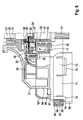
- a motor-driven hand grinder 10 is shown schematically in the form of a power tool, as it is used for floor and wall processing.
- the hand grinder 10 can od as a cleaning machine, concrete and Esstrichschleifer, drywall grinder. Like. Hand tools are formed or used.
- the hand grinder 10 has an only schematically indicated grinding plate 11 in a grinding head housing 12.
- the sanding pad 11 is rotatably connected to an output shaft 13, via which the sanding pad 11 is rotatably driven in a working direction with the hand grinder 10 switched on at a speed of z. B. about 1700 U / min. With this speed, the output shaft 13 rotates.
- the output shaft 13 is drivable by means of a drive motor, which is located in a handle 14 and not shown, via a first gear stage 15 and a drive shaft 16 with a downstream reduction gear 17 as the second gear stage.
- the first gear stage 15 which is arranged in a gear between the drive motor and the drive shaft 16, the engine output speed, the z. B. 40000 U / min may be, to a predetermined speed of the drive shaft 16, the z. B. 11000 U / min may be reduced.
- the first gear 15 is formed as a bevel gear with an engine-side pinion 18 and a gear engaged therewith ring gear 19 which is held on the drive shaft 16 with a press fit.
- At least one Sauggebläserad 20 is rotatably held as part of a dust extraction, preferably with interference fit.
- the suction fan 20 forms the impeller of a radial fan. It runs like the drive shaft 16 at a high speed z. B. of 11000 U / min and thus forms a powerful fan of an integrated dust extraction, which can promote a large volume flow z. On the order of 1600 l / min.
- the reduction gear 17 as a second gear stage, the high speed of the drive shaft 16 in a stage of about 11000 U / min to z. B. max. 1700 rpm reduced. Also a multi-stage reduction can be provided.
- the drive shaft 16 is mounted on at least one shaft portion 21 by means of a bearing 22, in particular a roller bearing, wherein preferably the inner ring 23 of the bearing 22 is held with a press fit on the drive shaft 16 and the outer ring 24 of the bearing 22 is preferably encapsulated by a bearing carrier 25 and is held.
- the bearing 22 is located axially between the ring gear 19 and the Sauggebläserad 20th
- the reduction gear 17 is formed of a planetary gear which is disposed between the drive shaft 16 and the output shaft 13.
- This planetary gear has a sun gear 26 which is either integral with the drive shaft 16, z. B. is cut into this, or consists of a held on the drive shaft 16 by press connection pinion.
- the reduction gear 17 in the form of the planetary gear also has a z. B. disc-shaped planet carrier 27 which is rotatably connected to the output shaft 13, z. B. is held on this with a press fit.
- the planet carrier 27 has, for example, three bearing pins 28 held thereon with a press fit for corresponding planetary gears 29, which rotate in the ring gear 30.
- the center axes of the sun gear 26, the ring gear 30 and the planet carrier 27 of the reduction gear 17 extend coaxially to the drive shaft 16 and output shaft 13.
- the output shaft 13 is mounted on a shaft portion 31 between the planet gear 27 and the at least one sanding pad 11 by means of two roller bearings 32, 33, the respective inner ring is held on the output shaft 13 by press fit and their respective outer ring received in a cylindrical sleeve-like part 34 of the grinding head housing 11 and held by a bearing cap 35.
- the bearings 32, 33 may be encapsulated by a bearing carrier.
- the grinding head housing 12 consists of a lower part 36 and an upper hood 37, which is connected to the lower part 36 and in which the Sauggebläserad 20 is arranged.
- the cylindrical part 34 in which the two bearings 32, 33 are received, is an integral part of the lower part 36.
- the reduction gear 17 is received in the form of the planetary gear and contained in a gear housing, the top side with a gear cover 38 Has bearing cap, which covers the ring gear 30 and the planetary gears 29 and holds down.
- the at least one suction fan 20 is held on the drive shaft 16 with interference fit and may be formed of a plastic part with injected metal bush or instead made of metal, for.
- the suction fan 20 has a closed top side support plate 39 and projecting from this, backward curved blades 40.
- the lower part 36 of the grinding head housing 12 is located directly below the Sauggebläserades 20 and the air deflection serving curved baffles 41, further on the top of Sauggebläserad 20 through open pockets 42 and a spiral space 43, which opens into an air outlet opening 44. How out Fig. 1 it can be seen, in the region of the air outlet opening 44 to the grinding head housing 12, a flexible hose 45 is connected, for. B. by means of a quick coupling element.
- the Sauggebläserad 20 has a neck 46, with which the Sauggebläserad 20 is held on the drive shaft 16 with a press fit, wherein axially to the neck 46 is followed by a larger diameter stepped inner annular groove 47, the disassembly, z. B. for repair purposes.
- annular groove 47 is a puller stop, which can be supported for disassembly on the drive shaft 16.
- a shaft seal 48 is held to seal.
- the drive shaft 16 is with her in Fig. 1 upper end portion by means of a local bearing 49, in particular needle bearing, stored.
- Due to the angular gear with pinion 18 and ring gear 19 results, viewed in the axial direction of the drive shaft 16 and the output shaft 13, a compact construction with low height, wherein the drive motor, not shown housing forms the handle 14. It can be seen that the press connections of the ring gear 19, the inner ring 23 and the Sauggebläserades 20 are relatively easy to produce with the drive shaft 16, because these components are connected in the axial direction to stop.
- the blade geometry is optimized in terms of efficiency.
- the dust air flow is already optimally deflected before entering the Sauggebläserad 20. This is done by the air deflection serving curved baffles 41 of the lower part 36.
- the lower part 36 has z. B. twelve such baffles 41. These serve not only to redirect the air flow but at the same time cause a stabilization of the receiving area for the reduction gear 17 in the form of the planetary gear. Due to the design of the baffles 41 z. B. six circumferentially distributed seats with through holes 51 are formed for screws 52 which engage in aligned screw domes 53 of the gear cover 38 for fixing this.
- the pockets 42 formed at the base 36 enhance the stability of the base 36. Since these are open upwardly toward the suction fan 20, no sanding dust can accumulate therein during operation. To ensure this, the Sauggebläserad 30 is closed on the upper side by means of the support plate 39. This in turn has the advantage that thereby a higher volume flow can be promoted by the suction fan 20, z. On the order of 1600 l / min.
- the grinding head housing 12, in particular the lower part 36, has a lower edge 54, with which the lower part 36 surrounds the circumference of the grinding disc 11 with a radial spacing to form an annular space 55 therebetween.
- annular space 55 Through the annular space 55 a circumferential gap is formed, through the edge of an extraction of air, laden with dust and other Abtragp
- the brush ring body 57 has a brush holder 58 with bristles 59 on it and that the brush holder 58 is resiliently mounted in the annular groove 56, which is schematically indicated by a spring 60. Because of this resilient storage, the brush ring body 57 adapts to the situation automatically. The spring travel of this resiliently movable brush holder 56 can also be limited by appropriate means.
- the grinding head housing 12, in particular the lower part 36, has at least one removable wall element 62 on a front peripheral region 61. This has at both ends in respective slots 63, 64 form-fitting insertable from above engaging portions 65 and 66, respectively.
- the inserted wall element 62 can be detachably connected to the lower part 36 by means of a clip connection.
- the wall element 62 has two spaced resilient clip hooks 67, 68. Each of the clip hooks 67, 68 is associated with an approximately slot-shaped through opening 69, 70 in the lower part 36, into which the clip hooks 67, 68 can retract when being attached.
- Fig. 4 shows a state in which the wall member 62 is lifted from the lower part 36 upwards.
- the front peripheral region 61 of the local area of the grinding plate 11 is free. This allows close to the edge grinding.
- the wall element 62 this is in Fig. 4 moved downward, wherein the engaging portions 65, 66 enter positively into the slots 63, 64 of the lower part 36.
- the Klipshaken 67, 68 pass through the insertion opening 69, 70 by compression and spring behind them, the hook part of the Klipshaken 67, 68, the lower part 36 overlaps the underside, as in Fig. 7 is indicated.
- the wall element 62 is also provided with a retaining clip 71 which has two resilient tongues 72, 73 with an approximately hook-shaped projection 74, 75 at the end, which is directed radially outward.
- This projection 74, 75 engages under a respective brush holder 58 of the respective brush ring body 57, so that this thereby against falling out of the annular groove 56th is secured.
- the abrasive body housing 12, in particular the lower part 36 has approximately arcuate recesses 76 for this Halteklipse 71, said recesses 76 also form Ansaugbypässe. Due to these bypasses ambient air can flow into the lower hood area, whereby a better Absaug is achieved and is further achieved that the surface of the brush ring body 57 are released during operation of dust deposits.
- the described hand grinder 10 can be used with great advantage, z. B. for sanding drywall, plaster surfaces, plaster surfaces od. Like. It is also suitable for removing carpet adhesive, wallpaper scraps and similar coatings. Also can be by means of this electric hand tool z. B. create perforations of wallpaper and other similar surfaces. Also wood, paint or the like can be sanded with it. Furthermore, various surfaces can be brushed, smoothed, polished and treated in any other way by means of the hand grinder. Even a compacting of still moist plaster surfaces is possible.
- the hand grinder 10 allows a very effective dust extraction by powerful fan. There is no need for a vacuum cleaner for dust extraction, no other device. It requires only the illustrated hand grinder 10.
- the large volume flow generated by the fan, which is loaded with Abtragp firmwaren can, for example via the hose 45 z. B. are blown into a connected thereto filter device and pressed through it, wherein the Abtragp motherboard be filtered off.
- a brush ring ring can be provided, which is held spring-loaded in the same way and secured against falling out by means of the retaining clips 71. Because of this brush ring body 57 or a single brush ring ring a very good adaptation to the surface to be machined is possible, with a quick and easy replacement can be made in case of wear or damage.
Landscapes
- Engineering & Computer Science (AREA)
- Mechanical Engineering (AREA)
- Finish Polishing, Edge Sharpening, And Grinding By Specific Grinding Devices (AREA)
Applications Claiming Priority (1)
| Application Number | Priority Date | Filing Date | Title |
|---|---|---|---|
| DE201110076627 DE102011076627A1 (de) | 2011-05-27 | 2011-05-27 | Motorgetriebenes Handschleifgerät |
Publications (2)
| Publication Number | Publication Date |
|---|---|
| EP2527089A1 true EP2527089A1 (fr) | 2012-11-28 |
| EP2527089B1 EP2527089B1 (fr) | 2013-11-20 |
Family
ID=46045761
Family Applications (1)
| Application Number | Title | Priority Date | Filing Date |
|---|---|---|---|
| EP12163877.9A Not-in-force EP2527089B1 (fr) | 2011-05-27 | 2012-04-12 | Appareil de meulage manuel motorisé |
Country Status (2)
| Country | Link |
|---|---|
| EP (1) | EP2527089B1 (fr) |
| DE (1) | DE102011076627A1 (fr) |
Cited By (9)
| Publication number | Priority date | Publication date | Assignee | Title |
|---|---|---|---|---|
| EP3208039A1 (fr) * | 2016-02-17 | 2017-08-23 | HILTI Aktiengesellschaft | Meuleuse d'angle a collecteur de poussieres |
| EP3208040A1 (fr) * | 2016-02-17 | 2017-08-23 | HILTI Aktiengesellschaft | Meuleuse d'angle a collecteur de poussieres |
| CN107214578A (zh) * | 2017-06-15 | 2017-09-29 | 梁美萍 | 一种磨墙机 |
| EP3450099A1 (fr) * | 2017-08-28 | 2019-03-06 | Siprotool AG | Machine de meulage de surface destinée au meulage et au polissage du sol |
| CN109955126A (zh) * | 2019-04-29 | 2019-07-02 | 德仁天下(北京)环保科技有限公司 | 一种自动化石材墙面打磨抛光的无尘设备 |
| CN110405560A (zh) * | 2019-08-15 | 2019-11-05 | 傲基科技股份有限公司 | 集尘组件和墙面打磨机 |
| CN110900400A (zh) * | 2019-12-03 | 2020-03-24 | 永康市灵威电器有限公司 | 角磨机防尘组件 |
| WO2021159730A1 (fr) * | 2020-02-11 | 2021-08-19 | 广东博智林机器人有限公司 | Ponceuse à mastic |
| CN118720892A (zh) * | 2024-06-28 | 2024-10-01 | 江苏东成机电科技有限公司 | 墙面打磨机 |
Families Citing this family (5)
| Publication number | Priority date | Publication date | Assignee | Title |
|---|---|---|---|---|
| DE102015112059B4 (de) | 2015-07-23 | 2021-09-30 | Metabowerke Gmbh | Langhalsschleifer |
| CN107309755A (zh) * | 2017-07-26 | 2017-11-03 | 苏州标杆知识产权运营有限公司 | 一种多角度打磨机 |
| CN111673591A (zh) * | 2020-06-11 | 2020-09-18 | 滕治富 | 一种船舶维修用打磨抛光装置 |
| CN112605813B (zh) * | 2021-01-12 | 2022-09-13 | 安徽跃腾工艺制造有限公司 | 一种金属雕刻后去毛刺抛光除废设备 |
| CN113084618B (zh) * | 2021-03-01 | 2022-05-10 | 吾尚良品环境服务(上海)有限公司 | 一种环保型石材养护打磨机用的环保型打磨头 |
Citations (6)
| Publication number | Priority date | Publication date | Assignee | Title |
|---|---|---|---|---|
| DE19809237A1 (de) * | 1997-03-21 | 1998-09-24 | Hans Sauer Gmbh | Handarbeitsmaschine |
| US6007412A (en) * | 1998-01-30 | 1999-12-28 | Hutchins Manufacturing Company | Rotary abrading or polishing tool |
| US20060073778A1 (en) * | 2004-09-29 | 2006-04-06 | Alan Phillips | Drywall sander |
| WO2008014806A1 (fr) * | 2006-08-02 | 2008-02-07 | A & M Electric Tools Gmbh | Outil électronique guidé à la main avec un engrenage planétaire |
| EP1925401A1 (fr) | 2006-11-22 | 2008-05-28 | Festool GmbH | Meuleuse portative à moteur avec mécanisme d'aspiration réglable |
| WO2010072168A1 (fr) * | 2008-12-25 | 2010-07-01 | 上海卓特工具有限公司 | Broyeur électrique |
-
2011
- 2011-05-27 DE DE201110076627 patent/DE102011076627A1/de not_active Withdrawn
-
2012
- 2012-04-12 EP EP12163877.9A patent/EP2527089B1/fr not_active Not-in-force
Patent Citations (6)
| Publication number | Priority date | Publication date | Assignee | Title |
|---|---|---|---|---|
| DE19809237A1 (de) * | 1997-03-21 | 1998-09-24 | Hans Sauer Gmbh | Handarbeitsmaschine |
| US6007412A (en) * | 1998-01-30 | 1999-12-28 | Hutchins Manufacturing Company | Rotary abrading or polishing tool |
| US20060073778A1 (en) * | 2004-09-29 | 2006-04-06 | Alan Phillips | Drywall sander |
| WO2008014806A1 (fr) * | 2006-08-02 | 2008-02-07 | A & M Electric Tools Gmbh | Outil électronique guidé à la main avec un engrenage planétaire |
| EP1925401A1 (fr) | 2006-11-22 | 2008-05-28 | Festool GmbH | Meuleuse portative à moteur avec mécanisme d'aspiration réglable |
| WO2010072168A1 (fr) * | 2008-12-25 | 2010-07-01 | 上海卓特工具有限公司 | Broyeur électrique |
Cited By (14)
| Publication number | Priority date | Publication date | Assignee | Title |
|---|---|---|---|---|
| CN108698200A (zh) * | 2016-02-17 | 2018-10-23 | 喜利得股份公司 | 角磨机防尘罩 |
| EP3208039A1 (fr) * | 2016-02-17 | 2017-08-23 | HILTI Aktiengesellschaft | Meuleuse d'angle a collecteur de poussieres |
| WO2017140657A1 (fr) * | 2016-02-17 | 2017-08-24 | Hilti Aktiengesellschaft | Collecteur de poussière de meuleuse d'angle |
| WO2017140655A1 (fr) * | 2016-02-17 | 2017-08-24 | Hilti Aktiengesellschaft | Collecteur de poussière de meuleuse d'angle |
| EP3208040A1 (fr) * | 2016-02-17 | 2017-08-23 | HILTI Aktiengesellschaft | Meuleuse d'angle a collecteur de poussieres |
| CN108698199A (zh) * | 2016-02-17 | 2018-10-23 | 喜利得股份公司 | 角磨机防尘罩 |
| CN107214578B (zh) * | 2017-06-15 | 2023-11-03 | 梁美萍 | 一种磨墙机 |
| CN107214578A (zh) * | 2017-06-15 | 2017-09-29 | 梁美萍 | 一种磨墙机 |
| EP3450099A1 (fr) * | 2017-08-28 | 2019-03-06 | Siprotool AG | Machine de meulage de surface destinée au meulage et au polissage du sol |
| CN109955126A (zh) * | 2019-04-29 | 2019-07-02 | 德仁天下(北京)环保科技有限公司 | 一种自动化石材墙面打磨抛光的无尘设备 |
| CN110405560A (zh) * | 2019-08-15 | 2019-11-05 | 傲基科技股份有限公司 | 集尘组件和墙面打磨机 |
| CN110900400A (zh) * | 2019-12-03 | 2020-03-24 | 永康市灵威电器有限公司 | 角磨机防尘组件 |
| WO2021159730A1 (fr) * | 2020-02-11 | 2021-08-19 | 广东博智林机器人有限公司 | Ponceuse à mastic |
| CN118720892A (zh) * | 2024-06-28 | 2024-10-01 | 江苏东成机电科技有限公司 | 墙面打磨机 |
Also Published As
| Publication number | Publication date |
|---|---|
| DE102011076627A1 (de) | 2012-11-29 |
| EP2527089B1 (fr) | 2013-11-20 |
Similar Documents
| Publication | Publication Date | Title |
|---|---|---|
| EP2527089B1 (fr) | Appareil de meulage manuel motorisé | |
| DE2427450C3 (de) | Staubsaugvorrichtung | |
| DE10001467B4 (de) | Saugreinigungswerkzeug | |
| EP2349642A1 (fr) | Ponceuse pour plafond | |
| DE3003805C2 (de) | Druckluftbetriebene Handschleifmaschine | |
| DE2926725A1 (de) | Kuehlluftfilter fuer den brennkraftmotor, insbesondere fuer selbstfahrende landwirtschaftliche maschinen | |
| EP2228173B1 (fr) | Dispositif de polissage ou d'affilage avec un actionnement par air comprimé | |
| EP0017646A1 (fr) | Appareil de nettoyage à main | |
| EP2163356B1 (fr) | Machine-outil manuel dotée d'un capot de recouvrement et d'un raccordement d'évacuation de poussière | |
| DE1428388A1 (de) | Reinigungsvorrichtung fuer Schuhzeug,Polsterungen od.dgl. | |
| DE20312499U1 (de) | Schleifteller für Schleifmaschine | |
| DE60208557T2 (de) | Schleifblatt mit schlitzen zum staubsaugen, vorrichtung zur endbearbeitung von oberflächen und schleifblatthalterung | |
| DE102016100072A1 (de) | Schleifteller und Schleifmittel | |
| DE3444116A1 (de) | Hand-trennschleifmaschine mit staubabsaugung | |
| EP1778437B1 (fr) | Machine-outil manuelle, notamment ponceuse | |
| WO2007080003A1 (fr) | Machine-outil portative | |
| EP0576463A1 (fr) | Rotor pour une soufflante radiale | |
| DE102012001925A1 (de) | Oberflächenschleifer, insbesondere Betonschleifer | |
| EP1925401B1 (fr) | Meuleuse portative à moteur avec mécanisme d'aspiration réglable | |
| EP4395961A1 (fr) | Disque de broyage pour un dispositif de broyage et système de broyage | |
| DE10220858B4 (de) | Anlasservorrichtung für eine von einem Verbrennungsmotor betriebene Laubblasvorrichtung | |
| DE1121968B (de) | Schutz- und Absaugegehaeuse fuer Handschleif- oder dergleichen Maschinen | |
| DE970885C (de) | Elastische Aufhaengung eines ein Geblaese antreibenden Elektromotors | |
| DE102021132101A1 (de) | Bodenschleifmaschine | |
| WO2004094078A1 (fr) | Systeme de nettoyage pour nettoyer le revetement exterieur d'un avion |
Legal Events
| Date | Code | Title | Description |
|---|---|---|---|
| PUAI | Public reference made under article 153(3) epc to a published international application that has entered the european phase |
Free format text: ORIGINAL CODE: 0009012 |
|
| AK | Designated contracting states |
Kind code of ref document: A1 Designated state(s): AL AT BE BG CH CY CZ DE DK EE ES FI FR GB GR HR HU IE IS IT LI LT LU LV MC MK MT NL NO PL PT RO RS SE SI SK SM TR |
|
| AX | Request for extension of the european patent |
Extension state: BA ME |
|
| 17P | Request for examination filed |
Effective date: 20130528 |
|
| RBV | Designated contracting states (corrected) |
Designated state(s): AL AT BE BG CH CY CZ DE DK EE ES FI FR GB GR HR HU IE IS IT LI LT LU LV MC MK MT NL NO PL PT RO RS SE SI SK SM TR |
|
| GRAP | Despatch of communication of intention to grant a patent |
Free format text: ORIGINAL CODE: EPIDOSNIGR1 |
|
| RIC1 | Information provided on ipc code assigned before grant |
Ipc: B24B 23/02 20060101AFI20130624BHEP Ipc: B24B 55/10 20060101ALI20130624BHEP |
|
| INTG | Intention to grant announced |
Effective date: 20130724 |
|
| GRAS | Grant fee paid |
Free format text: ORIGINAL CODE: EPIDOSNIGR3 |
|
| GRAA | (expected) grant |
Free format text: ORIGINAL CODE: 0009210 |
|
| AK | Designated contracting states |
Kind code of ref document: B1 Designated state(s): AL AT BE BG CH CY CZ DE DK EE ES FI FR GB GR HR HU IE IS IT LI LT LU LV MC MK MT NL NO PL PT RO RS SE SI SK SM TR |
|
| REG | Reference to a national code |
Ref country code: GB Ref legal event code: FG4D Free format text: NOT ENGLISH |
|
| REG | Reference to a national code |
Ref country code: CH Ref legal event code: EP |
|
| REG | Reference to a national code |
Ref country code: AT Ref legal event code: REF Ref document number: 641306 Country of ref document: AT Kind code of ref document: T Effective date: 20131215 |
|
| REG | Reference to a national code |
Ref country code: IE Ref legal event code: FG4D Free format text: LANGUAGE OF EP DOCUMENT: GERMAN |
|
| REG | Reference to a national code |
Ref country code: DE Ref legal event code: R096 Ref document number: 502012000224 Country of ref document: DE Effective date: 20140123 |
|
| REG | Reference to a national code |
Ref country code: NL Ref legal event code: VDEP Effective date: 20131120 |
|
| REG | Reference to a national code |
Ref country code: LT Ref legal event code: MG4D |
|
| PG25 | Lapsed in a contracting state [announced via postgrant information from national office to epo] |
Ref country code: IS Free format text: LAPSE BECAUSE OF FAILURE TO SUBMIT A TRANSLATION OF THE DESCRIPTION OR TO PAY THE FEE WITHIN THE PRESCRIBED TIME-LIMIT Effective date: 20140320 Ref country code: SE Free format text: LAPSE BECAUSE OF FAILURE TO SUBMIT A TRANSLATION OF THE DESCRIPTION OR TO PAY THE FEE WITHIN THE PRESCRIBED TIME-LIMIT Effective date: 20131120 Ref country code: NL Free format text: LAPSE BECAUSE OF FAILURE TO SUBMIT A TRANSLATION OF THE DESCRIPTION OR TO PAY THE FEE WITHIN THE PRESCRIBED TIME-LIMIT Effective date: 20131120 Ref country code: NO Free format text: LAPSE BECAUSE OF FAILURE TO SUBMIT A TRANSLATION OF THE DESCRIPTION OR TO PAY THE FEE WITHIN THE PRESCRIBED TIME-LIMIT Effective date: 20140220 Ref country code: FI Free format text: LAPSE BECAUSE OF FAILURE TO SUBMIT A TRANSLATION OF THE DESCRIPTION OR TO PAY THE FEE WITHIN THE PRESCRIBED TIME-LIMIT Effective date: 20131120 Ref country code: HR Free format text: LAPSE BECAUSE OF FAILURE TO SUBMIT A TRANSLATION OF THE DESCRIPTION OR TO PAY THE FEE WITHIN THE PRESCRIBED TIME-LIMIT Effective date: 20131120 Ref country code: LT Free format text: LAPSE BECAUSE OF FAILURE TO SUBMIT A TRANSLATION OF THE DESCRIPTION OR TO PAY THE FEE WITHIN THE PRESCRIBED TIME-LIMIT Effective date: 20131120 |
|
| PG25 | Lapsed in a contracting state [announced via postgrant information from national office to epo] |
Ref country code: ES Free format text: LAPSE BECAUSE OF FAILURE TO SUBMIT A TRANSLATION OF THE DESCRIPTION OR TO PAY THE FEE WITHIN THE PRESCRIBED TIME-LIMIT Effective date: 20131120 Ref country code: LV Free format text: LAPSE BECAUSE OF FAILURE TO SUBMIT A TRANSLATION OF THE DESCRIPTION OR TO PAY THE FEE WITHIN THE PRESCRIBED TIME-LIMIT Effective date: 20131120 Ref country code: RS Free format text: LAPSE BECAUSE OF FAILURE TO SUBMIT A TRANSLATION OF THE DESCRIPTION OR TO PAY THE FEE WITHIN THE PRESCRIBED TIME-LIMIT Effective date: 20131120 |
|
| PG25 | Lapsed in a contracting state [announced via postgrant information from national office to epo] |
Ref country code: PT Free format text: LAPSE BECAUSE OF FAILURE TO SUBMIT A TRANSLATION OF THE DESCRIPTION OR TO PAY THE FEE WITHIN THE PRESCRIBED TIME-LIMIT Effective date: 20140320 |
|
| PG25 | Lapsed in a contracting state [announced via postgrant information from national office to epo] |
Ref country code: EE Free format text: LAPSE BECAUSE OF FAILURE TO SUBMIT A TRANSLATION OF THE DESCRIPTION OR TO PAY THE FEE WITHIN THE PRESCRIBED TIME-LIMIT Effective date: 20131120 |
|
| REG | Reference to a national code |
Ref country code: DE Ref legal event code: R097 Ref document number: 502012000224 Country of ref document: DE |
|
| PG25 | Lapsed in a contracting state [announced via postgrant information from national office to epo] |
Ref country code: CZ Free format text: LAPSE BECAUSE OF FAILURE TO SUBMIT A TRANSLATION OF THE DESCRIPTION OR TO PAY THE FEE WITHIN THE PRESCRIBED TIME-LIMIT Effective date: 20131120 Ref country code: PL Free format text: LAPSE BECAUSE OF FAILURE TO SUBMIT A TRANSLATION OF THE DESCRIPTION OR TO PAY THE FEE WITHIN THE PRESCRIBED TIME-LIMIT Effective date: 20131120 Ref country code: SK Free format text: LAPSE BECAUSE OF FAILURE TO SUBMIT A TRANSLATION OF THE DESCRIPTION OR TO PAY THE FEE WITHIN THE PRESCRIBED TIME-LIMIT Effective date: 20131120 Ref country code: RO Free format text: LAPSE BECAUSE OF FAILURE TO SUBMIT A TRANSLATION OF THE DESCRIPTION OR TO PAY THE FEE WITHIN THE PRESCRIBED TIME-LIMIT Effective date: 20131120 |
|
| PLBE | No opposition filed within time limit |
Free format text: ORIGINAL CODE: 0009261 |
|
| STAA | Information on the status of an ep patent application or granted ep patent |
Free format text: STATUS: NO OPPOSITION FILED WITHIN TIME LIMIT |
|
| PG25 | Lapsed in a contracting state [announced via postgrant information from national office to epo] |
Ref country code: DK Free format text: LAPSE BECAUSE OF FAILURE TO SUBMIT A TRANSLATION OF THE DESCRIPTION OR TO PAY THE FEE WITHIN THE PRESCRIBED TIME-LIMIT Effective date: 20131120 |
|
| 26N | No opposition filed |
Effective date: 20140821 |
|
| PG25 | Lapsed in a contracting state [announced via postgrant information from national office to epo] |
Ref country code: LU Free format text: LAPSE BECAUSE OF FAILURE TO SUBMIT A TRANSLATION OF THE DESCRIPTION OR TO PAY THE FEE WITHIN THE PRESCRIBED TIME-LIMIT Effective date: 20140412 Ref country code: MC Free format text: LAPSE BECAUSE OF FAILURE TO SUBMIT A TRANSLATION OF THE DESCRIPTION OR TO PAY THE FEE WITHIN THE PRESCRIBED TIME-LIMIT Effective date: 20131120 |
|
| REG | Reference to a national code |
Ref country code: DE Ref legal event code: R097 Ref document number: 502012000224 Country of ref document: DE Effective date: 20140821 |
|
| REG | Reference to a national code |
Ref country code: IE Ref legal event code: MM4A |
|
| PG25 | Lapsed in a contracting state [announced via postgrant information from national office to epo] |
Ref country code: SI Free format text: LAPSE BECAUSE OF FAILURE TO SUBMIT A TRANSLATION OF THE DESCRIPTION OR TO PAY THE FEE WITHIN THE PRESCRIBED TIME-LIMIT Effective date: 20131120 |
|
| PG25 | Lapsed in a contracting state [announced via postgrant information from national office to epo] |
Ref country code: IT Free format text: LAPSE BECAUSE OF FAILURE TO SUBMIT A TRANSLATION OF THE DESCRIPTION OR TO PAY THE FEE WITHIN THE PRESCRIBED TIME-LIMIT Effective date: 20131120 |
|
| PG25 | Lapsed in a contracting state [announced via postgrant information from national office to epo] |
Ref country code: IE Free format text: LAPSE BECAUSE OF NON-PAYMENT OF DUE FEES Effective date: 20140412 |
|
| REG | Reference to a national code |
Ref country code: CH Ref legal event code: PL |
|
| PG25 | Lapsed in a contracting state [announced via postgrant information from national office to epo] |
Ref country code: CH Free format text: LAPSE BECAUSE OF NON-PAYMENT OF DUE FEES Effective date: 20150430 Ref country code: LI Free format text: LAPSE BECAUSE OF NON-PAYMENT OF DUE FEES Effective date: 20150430 |
|
| PG25 | Lapsed in a contracting state [announced via postgrant information from national office to epo] |
Ref country code: MT Free format text: LAPSE BECAUSE OF FAILURE TO SUBMIT A TRANSLATION OF THE DESCRIPTION OR TO PAY THE FEE WITHIN THE PRESCRIBED TIME-LIMIT Effective date: 20131120 |
|
| REG | Reference to a national code |
Ref country code: FR Ref legal event code: PLFP Year of fee payment: 5 |
|
| PG25 | Lapsed in a contracting state [announced via postgrant information from national office to epo] |
Ref country code: SM Free format text: LAPSE BECAUSE OF FAILURE TO SUBMIT A TRANSLATION OF THE DESCRIPTION OR TO PAY THE FEE WITHIN THE PRESCRIBED TIME-LIMIT Effective date: 20131120 |
|
| PG25 | Lapsed in a contracting state [announced via postgrant information from national office to epo] |
Ref country code: BG Free format text: LAPSE BECAUSE OF FAILURE TO SUBMIT A TRANSLATION OF THE DESCRIPTION OR TO PAY THE FEE WITHIN THE PRESCRIBED TIME-LIMIT Effective date: 20131120 Ref country code: GR Free format text: LAPSE BECAUSE OF FAILURE TO SUBMIT A TRANSLATION OF THE DESCRIPTION OR TO PAY THE FEE WITHIN THE PRESCRIBED TIME-LIMIT Effective date: 20140221 Ref country code: CY Free format text: LAPSE BECAUSE OF FAILURE TO SUBMIT A TRANSLATION OF THE DESCRIPTION OR TO PAY THE FEE WITHIN THE PRESCRIBED TIME-LIMIT Effective date: 20131120 |
|
| PG25 | Lapsed in a contracting state [announced via postgrant information from national office to epo] |
Ref country code: TR Free format text: LAPSE BECAUSE OF FAILURE TO SUBMIT A TRANSLATION OF THE DESCRIPTION OR TO PAY THE FEE WITHIN THE PRESCRIBED TIME-LIMIT Effective date: 20131120 Ref country code: BE Free format text: LAPSE BECAUSE OF FAILURE TO SUBMIT A TRANSLATION OF THE DESCRIPTION OR TO PAY THE FEE WITHIN THE PRESCRIBED TIME-LIMIT Effective date: 20140430 Ref country code: HU Free format text: LAPSE BECAUSE OF FAILURE TO SUBMIT A TRANSLATION OF THE DESCRIPTION OR TO PAY THE FEE WITHIN THE PRESCRIBED TIME-LIMIT; INVALID AB INITIO Effective date: 20120412 |
|
| REG | Reference to a national code |
Ref country code: FR Ref legal event code: PLFP Year of fee payment: 6 |
|
| REG | Reference to a national code |
Ref country code: FR Ref legal event code: PLFP Year of fee payment: 7 |
|
| REG | Reference to a national code |
Ref country code: AT Ref legal event code: MM01 Ref document number: 641306 Country of ref document: AT Kind code of ref document: T Effective date: 20170412 |
|
| PG25 | Lapsed in a contracting state [announced via postgrant information from national office to epo] |
Ref country code: MK Free format text: LAPSE BECAUSE OF FAILURE TO SUBMIT A TRANSLATION OF THE DESCRIPTION OR TO PAY THE FEE WITHIN THE PRESCRIBED TIME-LIMIT Effective date: 20131120 |
|
| PG25 | Lapsed in a contracting state [announced via postgrant information from national office to epo] |
Ref country code: AT Free format text: LAPSE BECAUSE OF NON-PAYMENT OF DUE FEES Effective date: 20170412 |
|
| PG25 | Lapsed in a contracting state [announced via postgrant information from national office to epo] |
Ref country code: AL Free format text: LAPSE BECAUSE OF FAILURE TO SUBMIT A TRANSLATION OF THE DESCRIPTION OR TO PAY THE FEE WITHIN THE PRESCRIBED TIME-LIMIT Effective date: 20131120 |
|
| PGFP | Annual fee paid to national office [announced via postgrant information from national office to epo] |
Ref country code: FR Payment date: 20190423 Year of fee payment: 8 |
|
| PGFP | Annual fee paid to national office [announced via postgrant information from national office to epo] |
Ref country code: GB Payment date: 20190424 Year of fee payment: 8 Ref country code: DE Payment date: 20190627 Year of fee payment: 8 |
|
| REG | Reference to a national code |
Ref country code: DE Ref legal event code: R119 Ref document number: 502012000224 Country of ref document: DE |
|
| PG25 | Lapsed in a contracting state [announced via postgrant information from national office to epo] |
Ref country code: DE Free format text: LAPSE BECAUSE OF NON-PAYMENT OF DUE FEES Effective date: 20201103 Ref country code: FR Free format text: LAPSE BECAUSE OF NON-PAYMENT OF DUE FEES Effective date: 20200430 |
|
| GBPC | Gb: european patent ceased through non-payment of renewal fee |
Effective date: 20200412 |
|
| PG25 | Lapsed in a contracting state [announced via postgrant information from national office to epo] |
Ref country code: GB Free format text: LAPSE BECAUSE OF NON-PAYMENT OF DUE FEES Effective date: 20200412 |