EP2528523B1 - Chirurgisches instrumentarium - Google Patents
Chirurgisches instrumentarium Download PDFInfo
- Publication number
- EP2528523B1 EP2528523B1 EP10798801.6A EP10798801A EP2528523B1 EP 2528523 B1 EP2528523 B1 EP 2528523B1 EP 10798801 A EP10798801 A EP 10798801A EP 2528523 B1 EP2528523 B1 EP 2528523B1
- Authority
- EP
- European Patent Office
- Prior art keywords
- implant
- fixing device
- introduction
- supporting element
- locking
- Prior art date
- Legal status (The legal status is an assumption and is not a legal conclusion. Google has not performed a legal analysis and makes no representation as to the accuracy of the status listed.)
- Active
Links
Images











Classifications
-
- A—HUMAN NECESSITIES
- A61—MEDICAL OR VETERINARY SCIENCE; HYGIENE
- A61B—DIAGNOSIS; SURGERY; IDENTIFICATION
- A61B17/00—Surgical instruments, devices or methods
- A61B17/56—Surgical instruments or methods for treatment of bones or joints; Devices specially adapted therefor
- A61B17/58—Surgical instruments or methods for treatment of bones or joints; Devices specially adapted therefor for osteosynthesis, e.g. bone plates, screws or setting implements
- A61B17/68—Internal fixation devices, including fasteners and spinal fixators, even if a part thereof projects from the skin
- A61B17/70—Spinal positioners or stabilisers, e.g. stabilisers comprising fluid filler in an implant
- A61B17/7062—Devices acting on, attached to, or simulating the effect of, vertebral processes, vertebral facets or ribs ; Tools for such devices
- A61B17/7065—Devices with changeable shape, e.g. collapsible or having retractable arms to aid implantation; Tools therefor
-
- A—HUMAN NECESSITIES
- A61—MEDICAL OR VETERINARY SCIENCE; HYGIENE
- A61B—DIAGNOSIS; SURGERY; IDENTIFICATION
- A61B17/00—Surgical instruments, devices or methods
- A61B2017/0023—Surgical instruments, devices or methods disposable
-
- A—HUMAN NECESSITIES
- A61—MEDICAL OR VETERINARY SCIENCE; HYGIENE
- A61B—DIAGNOSIS; SURGERY; IDENTIFICATION
- A61B90/00—Instruments, implements or accessories specially adapted for surgery or diagnosis and not covered by any of the groups A61B1/00 - A61B50/00, e.g. for luxation treatment or for protecting wound edges
- A61B90/06—Measuring instruments not otherwise provided for
- A61B2090/061—Measuring instruments not otherwise provided for for measuring dimensions, e.g. length
-
- A—HUMAN NECESSITIES
- A61—MEDICAL OR VETERINARY SCIENCE; HYGIENE
- A61B—DIAGNOSIS; SURGERY; IDENTIFICATION
- A61B90/00—Instruments, implements or accessories specially adapted for surgery or diagnosis and not covered by any of the groups A61B1/00 - A61B50/00, e.g. for luxation treatment or for protecting wound edges
- A61B90/06—Measuring instruments not otherwise provided for
- A61B2090/064—Measuring instruments not otherwise provided for for measuring force, pressure or mechanical tension
Definitions
- the invention relates to a surgical instrument, comprising an implant for mutual support of an upper spinous process of a first vertebral body by means of an upper support surface and a lower spinous process of a second vertebral body by means of a lower support surface, the implant a first implant component and a relative to this movable along a clamping direction formed second implant component comprises, in order to convert the implant starting from a basic position in a direction transverse to the clamping direction spreading in a spread position in which the upper support surface and the lower support surface have a greater distance from each other than in the normal position, and wherein the implant at least one einbring workedes upper support member and at least one einbring devises lower support member for insertion-side lateral support of the upper spinous process or the lower spinous process in the Sprei Adjustment of the implant includes.
- An implant of the type mentioned is in the DE 20 2008 009 344 U1 described. It can be introduced in the basic position by a unilateral access from an insertion side into the body and positioned in the intervertebral space between the spinous processes. By transferring the implant from the basic position into the expanded position, the support surfaces increase their distance from one another, so that the spinous processes resting on the support surfaces can be more or less pushed apart to stabilize adjacent vertebral bodies relative to each other.
- the implant For lateral stabilization of the upper and lower vertebral bodies, the implant comprises at least one upper support element and a lower support element, each on the insertion side, ie from the side from which the implant is inserted into the body, which can support spinous processes.
- the support elements are also spread when transferring the implant from the basic position into the spread position relative to each other, wherein they approach each starting from the intervertebral space to the spinous processes.
- the implant can comprise at least one upper support element and at least one lower support element, which can laterally support the upper and lower spinous processes on the body side, ie, on the side of the spinous processes facing away from the insertion side.
- Object of the present invention is to develop a generic surgical instruments so that it has an improved handling.
- the instrumentation comprises a fixation device for the implant for spreading the at least one insertion side upper support member and the at least one insertion side lower support member relative to each other along the spreading, by means of which fixing the implant starting from the basic position can be brought into an insertion position in which the at least one insertion-side upper support member and the at least one insertion-side lower support member have a greater distance relative to each other than in the normal position, and from the implant by moving the second implant component relative to the first implant component along the clamping direction in the spread position can be transferred.
- Advantageous developments of the invention are the subject of the dependent claims.
- the fixing device the implant can be brought from a basic position into an insertion position.
- the at least one insertion-side upper support element and the at least one insertion-side lower support element thereby get relative to one another at a distance which is greater than their distance from one another in the basic position of the implant.
- a distance between an upper support element and a lower support element are achieved, which is greater than the distance of the upper and lower spinous process from each other.
- the support elements thus form stops for the spinous processes, so that the maximum insertion depth of the implant is limited in the intervertebral space. This makes it easier for a surgeon to handle the implant, and the support elements can be approximately at the point for engagement with the spinous processes, which they can also take in the spread position of the implant. This means that the implant can be positioned better relative to the spinous processes. In addition, it is ensured that an operator does not bring the implant too deeply into the intervertebral space, it can therefore be worked less invasive, and a risk of injury to the patient is reduced.
- the fixing device preferably comprises a receptacle in which the implant is held, at least partially. Additionally or alternatively, the implant may comprise a receptacle in which the fixing device, at least partially, is held.
- the fixation device can thereby be connected to the implant so that it can be brought from the basic position into the insertion position.
- the fixing device comprises or form at least one first upper stop acting counter to the spreading direction for the at least one insertion-side upper supporting element or a carrier comprising it and / or if the fixing device has at least one first lower stop acting against the spreading direction for the at least one einbring workede lower support member or a comprehensive this carrier comprises or forms.
- This gives a simple constructive possibility to spread the upper support member and the lower support member against each other to increase their distance from each other in the insertion position of the implant compared to the basic position of the implant.
- the at least one insertion-side upper support element or the support comprising it rests against the at least one first upper stop in the insertion position of the implant and / or if the at least one insertion-side lower support element or the support comprising it is in the insertion position of the implant is applied to the at least one first lower stop.
- the first upper and / or the first lower stop each comprise a contact surface for the respective expansion element or the respective carrier.
- the fixing device comprises or form at least one second upper stop acting in the spreading direction for the at least one insertion-side upper supporting element or a carrier comprising it and / or if the fixing device has at least one second lower stop acting on the spreading direction for the at least one einbring workede lower support member or a comprehensive this carrier comprises or forms.
- This makes it possible to ensure in a simple constructive manner that in the insertion position, the upper and lower support member along the spreading direction a maximum distance, which is given by the distance of the second upper stop and the second lower stop from each other, not exceed. This makes it possible to avoid damage to the implant in the insertion position.
- the at least one insertion-side upper support element or the support comprising it rests against the at least one second upper stop in the insertion position of the implant and / or if the at least one insertion-side lower support element or the support comprising it is in the insertion position of the implant at least one second lower stop abuts.
- the second upper and / or the second lower stop each comprise a contact surface for the respective support element or the respective carrier.
- the at least one insertion-side upper support element is positively arranged between the at least one first upper stop and the at least one second upper stop and that the at least one insertion-side lower support element between the at least one first lower stop and the at least one second lower stop is arranged to ensure a reliable fixation of the implant.
- the fixing device comprises or forms at least one insertion-side upper bone stop element for the upper spinous process and / or if the fixing device comprises or forms at least one insertion-side lower bone stop element for the lower spinous process.
- This facilitates the handling of the implant.
- this can not only be applied to the upper or lower spinous process by means of the upper and lower support elements, but also by means of the fixing device. As a result, a more reliable positioning of the implant relative to the spinous processes can be achieved.
- the upper bone stop member and the lower bone stop member are conveniently spaced further apart relative to each other than the insertion side upper support member and the insertion side lower support member to facilitate handling the implant in the disc space.
- the first implant component comprises the at least one insertion-side upper support element and the at least one insertion-side lower support element. This has proved to be advantageous in practice for a simpler construction of the implant.
- the second implant component comprises at least one insertion-side upper support element and / or at least one insertion-side lower support element.
- the implant comprises at least one body-side upper support member and at least one body-side lower support member for body-side lateral support of the upper spinous process or the lower spinous process in the spread position of the implant.
- body side in the present case is regarded as the lateral side of the spinous processes which faces away from the lateral side of the spinous processes on which the implant is directed into the body.
- the upper support member and the lower support member allow the body side lateral support of the upper and lower spinous process and thereby also a more reliable support thereof relative to each other.
- the second implant component comprises the at least one body-side upper support element and the at least one body-side lower support element. This has proven to be advantageous in practice for a simpler structural design of the implant.
- the first implant component comprises at least one body-side upper support element and / or at least one body-side lower support element.
- the surgical instrumentation comprises a coupling device with at least one first coupling element coupled to an insertion-side support element and at least one second coupling element coupled to a body-side support element, which in the Insertion position of the implant with the at least one first coupling element cooperates to reduce the distance of the at least one body-side upper support member and the at least one body-side lower support member from each other relative to their distance from each other in the basic position of the implant.
- the at least one insertion-side upper support element and the at least one insertion-side lower support element have a greater distance from one another than in the basic position of the implant. This can be ensured by means of the fixing device.
- the additional coupling device it is further possible by means of the additional coupling device to reduce the distance of the at least one body-side upper support element and the at least one body-side lower support element from each other in the insertion position of the implant relative to their distance from each other in the basic position of the implant.
- This makes it possible to reduce the insertion height of the implant by means of the fixing device and the coupling device.
- This makes it easier for a surgeon to insert the implant into the intervertebral space.
- the risk is reducible that the surgeon when inserting the implant undesirably abuts the spinous processes or other body structures, such as ligaments, tendons or muscles. This considerably facilitates the handling of the implant.
- the coupling device comprises the at least one first coupling element and the at least one second coupling element which cooperate in the insertion position of the implant.
- the first and / or the second coupling element may, for example, be connected to the insertion-side or the body-side support element, in particular in one piece, in order to be coupled to it.
- the implant comprises or forms the coupling device, because this makes it possible to give the surgical instrument a simpler construction.
- the first implant component comprises the at least one first coupling element and that the at least one second implant component comprises the at least one second coupling element.
- the coupling device preferably comprises a first coupling element coupled to an insertion-side upper support element and a second coupling element interacting therewith and coupled to a body-side lower support element.
- the effect of the fixing device, together with the coupling device is opposite in relation to the insertion-side upper support element and the body-side lower support element.
- the farther the insertion-side upper support element is spread under the action of the fixing device relative to an insertion-side lower support element the closer the body-side lower support element reaches a body-side upper support element. It has been found in practice that the coupling device in this embodiment can have a simple construction and a reliable function of the coupling device can be ensured.
- the coupling device comprises a first coupling element coupled to an insertion-side lower support element and a second coupling element interacting therewith and coupled to a body-side upper support element.
- the at least one first coupling element and / or the at least one second coupling element at least partially form a support surface for a spinous process.
- the first and / or the second coupling element can thereby perform an additional function. This allows to give the implant a more compact design.
- the coupling device comprises a first coupling element for a delivery-side upper support element and a first coupling element for a delivery-side lower support element, which are spread further relative to each other by means of the fixing device in the insertion position of the implant along the spreading direction than in the basic position of the implant.
- two second coupling elements which interact with the first coupling elements, along the spreading direction, for example, when in each case a first coupling element and a second coupling element are mutually supported along the spreading direction.
- the spreading of the first coupling elements relative to each other is achieved by means of the fixing device, for example, under the action of the above-mentioned first upper stop for a einbring discoveredes upper support member and the first lower stop for a einbring workedes lower support member.
- the two first coupling elements are biased relative to each other along the spreading direction.
- the at least one first coupling element and / or the at least one second coupling element are designed elastically deformable, because a more reliable function of the coupling device and of the implant can be ensured thereby.
- the at least one first coupling element is formed as a the first insertion-carrying support member at a free end, which is a longitudinally effective Aufgleitelement for the at least one second coupling element is formed, and / or if the at least one second coupling element is formed as a the body-side support member at a free end comprehensive second carrier, which forms an effective along the spreading Aufgleitelement for the at least one first coupling element.
- a first coupling element and a second coupling element can each slide on one another and support one another, wherein they form a sliding element for the respective other coupling element. This sliding is effective along the spreading direction.
- the insertion-side support element and the body-side support element can thereby each be moved along the spreading direction until they can assume their position in the spread position of the implant. This allows a reliable function of the implant with a simple construction of the same.
- the surgical instrumentation comprises at least one blocking element for preventing a movement of a body-side support element along the spreading direction in the insertion position of the implant.
- the at least one body-side upper support element and the at least one body-side lower support element do not undesirably increase their distance from one another in the insertion position of the implant.
- the introduction height of the implant can be kept constant prior to its transfer into the spread position. A risk that a body-side support element undesirably contacts a spinous process or another body structure when introducing the implant is thereby reduced.
- the at least one blocking element comprises or forms a stop cooperating with the body-side support element or with a support comprising this body.
- the surgical instrumentation comprises more than just one blocking element, wherein a movement of a body-side support element along the spreading direction can be prevented by means of each blocking element.
- the fixing device comprises or forms the at least one blocking element.
- At least one blocking element can be placed in the insertion position of the implant on the body-side support element or on a comprehensive support and removable before transferring the implant from the insertion position into the spread position of the support member or from the carrier.
- the at least one blocking element is needed only until an operator wants to transfer the implant after insertion into the body of the insertion position in the spread position.
- the at least one blocking element can be applied to prevent the movement of the support element to the support element or to the carrier. This defines, for example, a blocking position of the at least one blocking element. If the surgeon wishes to transfer the implant into the spread position, he can remove the at least one blocking element from the support element or from the carrier and transfer it into a retracted position defined thereby.
- the at least one blocking element can be spread relative to one another between a first carrier comprising a body-side upper supporting element and a second carrier comprising a body-side lower supporting element, which can be spread relative to one another during the transfer of the implant from the insertion position into the spreading position along the spreading direction, formed intermediate space can be inserted and in particular form-fitting inserted.
- a reliable securing of the carrier against a spreading movement relative to each other can be ensured in a constructive manner.
- This also allows a movement of the upper body side and the body side prevent lower support element relative to each other along the spreading direction.
- the surgical instrumentation comprises at least one protective element for the implant, because it can be secured against damage.
- the at least one protective element is designed as an envelope which at least partially surrounds the implant on the implant side. This makes it possible to protect the implant, in particular on the insertion side, on which an operator typically attacks with a handling device for the implant or the like.
- the implant On the body side of the implant, i. In contrast to that region of the implant which is introduced through the intervertebral space between the spinous processes, the implant is preferably not surrounded by the sheath. As a result, only little space is required for introducing the implant into the intervertebral space.
- the sheath is about half of the implant, with respect to its extension along the clamping direction, surrounded to ensure reliable protection of the implant.
- the sheath at least partially surrounds the second implant component. This is then e.g. arranged delivery side, while the first implant component is arranged on the body side and is first introduced into the body.
- the fixing device preferably comprises or forms the at least one protective element. This makes it possible to give the instrument a particularly simple and compact design.
- the fixing device has a substantially U-shaped cross-section.
- the fixing device takes the form of a Staple in the form of a large U will be awarded. This provides the ability to form a protective element for the implant to protect it from three sides when the fixator is attached to the implant.
- the fixing device may comprise two segments forming the legs of the U spaced apart segments.
- the segments may be connected at one of their respective ends by means of a connecting segment.
- the first and second segments may comprise or form the at least one first upper stop described above, the at least one second upper stop, and a bone stop member or the at least one first lower stop, the at least one second lower stop, and a bone stop member include or train.
- a receptacle for one and in particular the first implant component can be formed on the connecting element.
- the implant component can be at least partially inserted into the receptacle and thus the fixation device can be attached to the implant.
- the fixing device is formed in one piece, because this simplifies their production.
- the fixing device is made of a plastic material, because this allows a cost-effective production of the fixing device.
- the fixing device may in particular be made of a deformable material. This, for example, gives the possibility of attaching the fixing device to the implant in a simpler manner or of releasing it from the implant.
- the fixing device is made of an elastically deformable material. This is particularly advantageous if the fixation device is to be attached to the implant and thereby deformed. Damage to the fixing device can be prevented.
- the fixing device is preassembled on the implant. This facilitates the handling of the instrumentation, since a surgeon does not have to attach the fixator prior to insertion on the implant.
- a fixing device mounted on the implant is detachable from this. After transferring the implant from the insertion position into the spread position, the fixing device is no longer needed, since the implant is intended to bear against the spinous processes. In this embodiment, therefore, the possibility is given to remove the fixing device after inserting the implant from the body.
- the fixing device is made of a resorbable material, and it is possible that it remains in the body after insertion of the implant in the intervertebral space.
- the fixing device forms at least a first Abziehlagerelement for removing the fixation device from the implant, because this gives a structurally simple way the ability to release the fixation device from the implant.
- a handling device of the instrumentation attack to release the fixation device from the implant.
- the fixing device preferably comprises or forms at least one peel-off stop element which is effective in a peeling direction oriented transversely to the clamping direction. This makes it possible to withdraw the fixing device transversely to the clamping direction, without influencing the position of the two implant components relative to one another, from the implant.
- the stripping direction can be aligned in particular perpendicular to the clamping direction.
- the stripping direction is aligned transversely and in particular perpendicular to the spreading direction. This makes it possible to remove the fixation device from the implant without affecting the upper and / or lower spinous process undesirably exerting this divergence force.
- the fixing device comprises or forms a first expansion bearing element for transferring the implant from the introduction position into the spread position. This makes it possible to give the instrument a more compact design. On the first Sp Schwarzlagerelement can act on the clamping direction effective spreading force for spreading the implant.
- the fixing device preferably comprises or forms at least one expansion stop element which acts along the tensioning direction.
- the possibility is given in a simple constructive manner that the fixing device forms a spreading bearing element.
- handle a handling device of the instrumentation to spread the implant attack.
- the at least one expansion stop element is coupled to a receptacle formed by the fixing device, in which one and preferably the first implant component is held.
- the Spreizanscherelement is coupled by means of recording, for example, non-positively and / or positively.
- the receptacle preferably comprises a stop acting on the clamping direction for the implant component.
- the above-mentioned shell forms a coupling element that couples the first expansion bearing element to the receptacle, wherein the latter and the at least one expansion bearing element are formed or covered by the shell.
- the surgical instrument has a holding device which comprises a receptacle for an implant component and in particular the second implant component in which it is partially held.
- the implant component and in particular the second implant component and thus also the implant can be held.
- the implant and preferably the second implant component comprises or forms a receptacle in which the holding device is held.
- the holding device forms a second Sp Drurslagerelement for transferring the implant from the Einbring too in the spread position. If an expanding force acting along the clamping direction acts on the holding device, the implant can thereby be transferred into the spread position.
- the counterforce required for this can, as mentioned above, attack the fixing device.
- the fixing device forms a guide element for the holding device when transferring the implant from the insertion position into the spread position. This makes it possible to move the holding device in a clearly defined direction relative to the fixing device and thereby to reliably transfer the implant into the spread position.
- the holding device may for example comprise or form a grip element.
- the holding device preferably comprises connection means for connecting to a first handling device of the surgical instrumentation for the implant.
- the Holding device can thus effectively form an intermediate piece between the handling device and the implant. This is advantageous if the holding device is a disposable part that is used with only one implant, whereas the first handling device is a multi-use tool.
- the connecting device is designed as a latching device, because this gives the possibility to connect the handling device in a simple manner with the holding device.
- the latching connection between the holding device and the handling device can be detachable.
- the implant has a locking element comprising a locking element, which locking element in the spread position of the implant from a release position in which the second implant component is movable relative to the first implant component along the clamping direction, in a direction aligned transversely to the clamping direction locking direction into a locking position, in which the second implant component is locked against a movement directed counter to the clamping direction on the first implant component.
- the locking element can be ensured that move the two implant components in the spread position of the implant is not relative to each other along the clamping direction.
- the implant retains the spread position after insertion into the body and can be effective for reliably supporting the spinous processes relative to each other.
- the locking element is held in the receptacle together with a fixing element encompassed by the second implant component and cooperating with the locking element for locking the implant.
- a reliable relative positioning of the locking element and the fixing element to each other can be ensured. This is both for the transfer of the locking element of the Release position in the locking position of advantage as well as when spreading the implant.
- the holding device comprises at least one first coupling member or forms this, which cooperates with at least one of the locking element encompassed or formed second coupling member for transferring the locking element from the release position into the locking position.
- the holding device can exercise a further function beyond the function for holding and possibly also for spreading the implant.
- the at least one first coupling member coupled to the at least one second coupling member of the locking element, so that it can be transferred by means of the holding device in the locking position. This facilitates the handling of the instruments.
- the at least one first coupling element is designed as a catch stop for the locking element that is effective along the locking direction.
- the at least one second coupling member is formed in a corresponding manner as a stop which cooperates with the driver stop. If the holding device is acted on by a force acting in the locking direction, the coupling elements couple together, so that the locking element can be transferred into the locking position.
- the holding device in the locking position of the locking element from the implant in the locking direction is removable.
- the holding device is no longer needed.
- it can be pulled off the implant in the locking direction, for example by continuing to act on it in the locking direction following the locking of the implant.
- the receptacle comprises an opening through which the fixing element and the locking element can be removed from the receptacle in the locking position of the locking element.
- the opening defines, for example, a cross-sectional area oriented transversely and in particular perpendicular to the locking direction, through which the fixing element and the locking element can be removed from the receptacle. This makes it possible to withdraw the holding device from the implant, and the fixing element and the locking element remain on the locked implant.
- the at least one coupling member of the holding device is conveniently arranged at an edge of the opening.
- the locking direction preferably has a parallel component to a removal direction for the fixing device from the implant, and in particular the locking direction is aligned parallel to the withdrawal direction. This allows both the fixing device and the holding device in the same direction - preferably perpendicular to the clamping direction and perpendicular to the spreading - deducted from the implant.
- the holding device is pre-mounted on the implant, because this facilitates a surgeon handling the instrument.
- the holding device can be attached to the implant.
- the above-mentioned recording is expandable, so that the fixing element and the locking element can be inserted into the receptacle to attach the implant to the holding device.
- the holding device is preferably part of the implant and is encompassed by the latter, in particular if it is preassembled on the implant.
- the holding device is part of the first handling device described below and is encompassed by it, in particular if it can be attached to the implant.
- the holding device it is advantageous if it is formed in one piece.
- the instrumentation can have a first handling device.
- a first handling device comprising a gripping element for holding the implant.
- the operating element can be manipulated in a user-friendly manner on the grip element in order to introduce the implant into the body.
- a surgical instrumentation of the type mentioned above with a handling device for holding an implant when the handling device has a handle element, allows a surgeon a user-friendly handling of the handling device and thus of the implant by acting on the handle element.
- the implant can be held directly by means of the first handling device.
- the first handling device comprises a connecting device for connecting to a holding device for the implant.
- a connecting device for connecting to a holding device for the implant This is conveniently the holding device described above for the implant, on which in turn the implant and in particular the second implant component is held.
- the connecting device is conveniently designed as a latching device, especially as a releasable latching device to a surgeon connecting the facilitate first handling device with the holding device and optionally to enable the release.
- the first handling device is designed as a longitudinal extension having a handle arm.
- the handle arm with longitudinal extension allows an operator a user-friendly introduction of the implant into the intervertebral space.
- the surgical instrumentation comprises a second handling device for the implant, which is designed to be movable relative to the first handling device and cooperates therewith for transferring the implant from the insertion position into the expanded position.
- a second handling device for the implant which is designed to be movable relative to the first handling device and cooperates therewith for transferring the implant from the insertion position into the expanded position.
- the second handling device is transferable relative to the first handling device from a first position to a second position, wherein one end of the second handling device along the clamping direction relative to an implant-holding end of the first handling device in the first position at a different distance than in the second Position. If the end of the second handling device engages in the transfer from the first position to the second position on the implant, an expanding force can thereby be introduced onto the implant, the required counterforce of which can be introduced to the implant with the first handling device.
- the second handling device is movably mounted on the first handling device.
- a particularly simple construction of the instrumentation can be achieved if the second handling device is designed as a pivoting lever.
- the second handling device comprises or forms at least one second expansion stop element, which interacts with at least one, preferably encompassed or formed by the fixing device, the first expansion stop element when transferring the implant from the insertion position into the spread position.
- the at least one second expansion stop element which is advantageously arranged at the end on the second handling device, can be applied to the at least one first expansion stop element.
- the second handling device comprises or form at least one second peel-off stop element which cooperates with at least one first peel-off stop element encompassed or formed by the fixing device for withdrawing the fixation device from the implant.
- a force acting along the pull-off direction can be exerted by the second handling device on the fixing device and thereby be removed from the implant.
- a counterforce required for this purpose can, for example, be exerted on the implant by the third handling device of the instrumentation described below.
- the at least one second peel-off stop element is arranged, for example, at the end on the second handling device.
- the at least one peel-off stop element is not encompassed or formed by the second handling device.
- the instrumentation may comprise a separate removal device with the at least one second removal stop element, which is formed separately from the second handling device.
- the surgical instrumentation comprises a locking device having a first blocking element encompassed by the first handling device and a second blocking element encompassed by the second handling device relative to each other from a blocking position in which the first blocking element and the second blocking element are relatively movable to block movement of the second handling device cooperate with the first handling device, in a release position, in which the first locking element and the second locking element do not cooperate and the second handling device is movable relative to the first handling device, and vice versa, can be transferred.
- the locking device can be ensured that the first and the second handling device is not undesirably move relative to each other. If the implant is introduced into the intervertebral space, the first and the second blocking element favorably assume the blocking position.
- the second handling device can be moved relative to the first handling device and thereby spreading the implant, i. be transferred from the insertion position in the spread position.
- the first blocking element and the second blocking element in the release position are biased relative to each other with respect to their blocking position.
- the blocking position can always take the blocking elements when the surgeon is not aware of them transferred to their release position or holds in this.
- the implant is typically spread in several small steps. The surgeon can thereby successively spread the implant by holding the locking elements in the release position, but then yields so far against the bias that they assume their blocking position. The implant is thus secured at each spreading step against spreading apart. This facilitates the handling of the instruments.
- the locking device In a structurally simple embodiment of the locking device, it is advantageous if it forms a locking mechanism.
- a blocking element for example the first blocking element
- a blocking element for example the second blocking element
- the locking rod can lock together with the locking lever in a plurality of locking positions.
- the locking lever can also be an actuating lever of the second handling device.
- the locking device desirably comprises at least one elastic element, for example in the form of a spring. This can impinge about the second locking element with a Sperrkaft, which must overcome the surgeon to transfer the locking elements from the locked position to the release position.
- the surgical instrumentation comprises a display device for displaying the relative position of the first handling device and the second handling device. Based on the display device, the surgeon can determine how far the implant is spread.
- the display device is calibrated so that the absolute distance of the upper and lower support surface from one another can be recognized by a surgeon.
- the surgical instrumentation comprises a third handling device for the implant, which is designed to be movable relative to the first handling device and which cooperates with the implant for removing the fixation device and / or a holding device or the first handling device from the implant in its spread position.
- a force can be exerted on the implant, which acts as a counter force to a peeling force for removing the fixing device from the implant.
- the counterforce for withdrawing the holding device or, if appropriate, a first handling device holding the implant directly from the implant can become effective. This allows easy handling of the instruments.
- the third handling device is transferable relative to the first handling device from a retracted position to a docking position, wherein at least one of the third handling device comprises or formed counter-stop element in the retracted position has a distance from the implant and abuts in the docking position on the latter.
- the at least one counter-stop element can in particular be arranged at the end on the third handling device.
- the third handling device is movably mounted on the first handling device. This allows reliable transfer of the third handling device from the retracted position to the docking position.
- the transfer of the third handling device has proved to be particularly reliable in practice, when the third handling device is slidably mounted on the first handling device along a direction parallel to the removal direction of the fixation device from the implant and / or parallel to the locking direction of the locking element direction.
- the third handling device is designed as a slide.
- the third handling device comprises a first segment with a counter stop element and a second segment with a counter stop element and if the counter stop element of the first segment has a spacing from the counter stop element of the second segment along the clamping direction.
- the first segment and the second segment can thereby be applied in the application position each with a counter-stop element on this side and beyond a connection region of the first handling device with the implant to this.
- the connection area is, with respect to the clamping direction, arranged between the counter-stop elements. If a tensile force pointing away from the implant acts on the first handling device, the first handling device can or the holding device can thereby be reliably detached from the implant without wedging or jamming.
- the counter-stop elements of the first segment and of the second segment, relative to the clamping direction can be applied laterally next to the holding device for the implant to the implant in the applying position. It has been found in practice that the holding device can be removed from the implant in a particularly reliable manner.
- the third handling device is designed as a slide as described above, it can encompass the first handling device, for example, wherein the first and second segments are arranged on opposite sides of the first handling device and / or the holding device.
- the third handling device forms at least one blocking element for preventing movement of a body-side support element along the spreading direction in the insertion position of the implant, which at least one blocking element in the insertion position on the body-side support member or on a comprehensive carrier can be applied, wherein the third handling device assumes a blocking position.
- the third handling device as described above, can be used in a blocking position to block the body-side support element before the implant is spread open, thus exerting an additional function.
- the at least one blocking element can engage, for example in the blocking position in a gap between two carriers, each comprising a body-side support member and the transfer of the implant from the insertion position into the spread position along the spreading direction are relatively spreadable to the movement of the support members relative to each other to block.
- the third handling device can be transferred from the retracted position into the blocking position and vice versa in the insertion position of the implant. This makes it possible, before the introduction of the implant into the body, to apply the at least one blocking element to the body-side supporting element or its carrier by transferring the third handling device from the retracted position into the blocking position. Before spreading the implant, the third handling device can again be transferred to the retracted position and the at least one blocking element can be placed at a distance from the implant.
- the at least one blocking element is formed at one end of the third handling device and in particular its second segment, or is covered by it.
- first segment is designed to be movable relative to the second segment and that the first segment and the second segment for transferring the third handling device from the retracted position to the blocking position and vice versa and / or from the retracted position in the landing position in each case by means of paired cooperating and covered by the first segment and the second segment or trained coupling elements couple.
- the coupling elements in this case form, for example, cooperating stop elements, in particular catch stop elements.
- the coupling elements effecting the coupling between the first segment and the second segment decouple from the retracted position into the blocking position for transferring the third handling device.
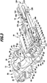
- the first preferred embodiment of a surgical instrumentation 10 which is shown partially in an exploded view, comprises an implant 12, a fixing device 14, a holding device 16 and furthermore a first, a second and a third handling device 18, 20 and 22 for the implant 12, the fixing device 14 and the holding device 16.
- the implant 12 is an intervertebral implant for mutual support of an upper spinous process 24 of a first vertebral body 25 and a lower spinous process 26 of a lower vertebral body 27. It belongs to a class of in the DE 20 2008 009 344 U1 described intervertebral implants.
- the implant 12 comprises a first implant component 28 and a second implant component 29 formed substantially identically thereto.
- the first implant component 28 comprises a first support segment 30 comprising two support arms 31 and 32 and a second support segment 33 comprising a first implant segment between the first support arm 31 and the second support arm 32 arranged support arm 34 includes.
- the support segments 30 and 33 are each formed from an elastically deformable material and held together on a first end side 35 of the implant 12 by means of a holding member 36 in the form of a C-shaped bracket 37.
- the second implant component 29 comprises a first support segment 38 with two support arms 39 and 40 spaced apart from each other and a second support segment 41 with a support arm 42 arranged between the support arms 39 and 40.
- the support segments 38 and 41 are likewise formed from an elastically deformable material , and they are near one of the end side 35 opposite end 43 of the implant 12 held together by means of a holding member 44 in the form of a C-shaped bracket 45.
- the implant components 28 and 29 are formed relative to each other with mirror symmetry with respect to a center of symmetry, not shown in the drawing. This has the consequence that the support arms 31 and 39, the support arms 32 and 40 and the support arms 34 and 42 can abut each other.
- Two clamping elements 46 and 47 fixed to the clamp 37 extend from the end face 35 to the end face 43. They pass through the implant 12 along its longitudinal extent. At the end 43 they are connected by means of a connecting member 48.
- the extension direction of the clamping elements 46 and 47 defines a clamping direction 49 of the implant 12, and together the clamping elements 46 and 47 form a tie rod 50 of the implant 12.
- FIG. 2A illustrated basic position in which the clip 45 is disposed near the connecting member 48, by applying force, for example, the bracket 45 along the clamping direction 49 in an example in the FIGS. 6 . 7 and 13 to show shown spread position.
- This is done by moving the second implant component 29 relative to the first implant component 28 along the tie rod 50.
- the support arms 31 and 39 each form slide-on elements for each other, the support arms 32 and 40 form slide-on elements for each other, and the support arms 34 and 42 form slide-on elements for each other.
- the support arms 31 and 39 are supported against each other and slide along each other.
- the support arms 32 and 40 and the support arms 34 and 42 are supported against each other and slide along each other.
- the implant 12 spreads in a spreading direction 51 oriented perpendicular to the clamping direction 49.
- the support arms 31 and 32 comprise at their free ends in each case a support element 55 or 56, which are referred to as "insertion-side” lower support elements for reasons that will be apparent hereinafter.
- the support arm 34 includes an insertion-side upper support member 57.
- the support arms 39 and 40 at their free ends each include a support member 58 and 59, which are hereinafter referred to as "bodyside” upper support members.
- the support arm 42 includes at its free end a body-side lower support member 60.
- the support arms 31, 32, 34, 39, 40 and 42 thus form support of the support members 55, 56, 57, 58, 59 and 60, respectively.
- the insertion-side support members 55, 56 and 57 laterally support the spinous processes 26 and 24, for example, abut against those sides of the spinous processes 24 and 26 which face an entrance into the human body through which the implant 12 is inserted into the body ( FIGS. 6 . 7 and 13 ).
- the body-side upper support elements 58, 59 and 60 can laterally support the spinous processes 24 and 26 and abut against them, for example, on the body side, ie. in each case on those sides of the spinous processes 24 and 26, which are remote from access for the implant 12.
- This distance d G defines the insertion height of the implant 12 in its normal position, and in particular, it must be smaller than the distance of the spinous processes 24 and 26 from each other, so that the implant 12 can be introduced into the intervertebral space.
- the instrumentation 10 comprises the fixing device 14 already mentioned.
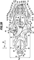
- the fixing device 14 is designed in the form of a sleeve 61 with a substantially U-shaped cross section.
- the sheath 61 has a first segment 62 and a second segment 63 spaced therefrom, which are connected to each other at one of their ends by a third segment 64.
- the sheath 61 comprises a first receptacle 65, into which the connecting member 48 can be inserted through an insertion opening 66.
- the first receptacle 65 is dimensioned so that the connecting member 48 can be placed in a form-fitting manner in the receptacle. This makes it possible to connect the connecting member 48 and thus the first implant component 28 and, in turn, the implant 12 to the sheath 61 or, in other words, to attach the sheath 61 to the implant 12.
- the connecting member 48 is engaged with the third segment 64.
- the envelope 61 On the side next to the first receptacle 65, the envelope 61 comprises a second receptacle 67, which is delimited on the upper side by the first segment 62 and at the bottom by the second segment 63.
- the second implant component 29 can be introduced into the second receptacle 67 at approximately half of its longitudinal extent, based on the distance of the clip 45 from the support elements 58 to 60.
- the second implant component 29 facing walls of the second receptacle 67, the are formed by the first and second segments 62 and 63, the contour of the support segments 41 and 38 are modeled.
- the second implant component 29 can be placed approximately in a form-fitting manner in the second receptacle 67 along the spreading direction 51.
- the sheath 61 is also held on the second implant component 29.
- the first segment 62 comprises, at a free end 69 facing away from the third segment 64, a first upper stop element 70 which is effective for the support arm 34 against the spreading direction 51, and a second upper stop element 71 which is effective for the support arm 34 in the spreading direction 51 is.
- the second segment 63 comprises at one, the third segment 64 remote from the free end 72 for the support arms 31 and 32 a counter to the spreading 51 effective first lower stop member 73 and effective for the support arms 31 and 32 in the spreading direction 51 second lower Stop element 74 ( FIG. 2B ).
- the lengths of the segments 62 and 63 are dimensioned such that, when the sheath 61 is attached to the implant 12, the support arms 31 and 32 are spread apart relative to the support arm 34 with respect to the home position along the spreading direction 51.
- the support arms 31 and 32 on the one hand and the support arm 34 on the other hand are in particular biased relative to each other.
- the support arms 31 and 32 and the support arm 34 are spread in this way relative to each other in a manner as is done even when transferring the implant 12 from the basic position into the spread position.
- the support arm 34 is supported by means of the insertion-side upper support member 57, and on the first lower stop member 73, the support arms 31 and 32 are supported by the insertion side lower support members 55 and 56, respectively, to the spreading of the support arms 32 and described above 33 to ensure relative to the support arm 34.
- the insertion-side support elements 55, 56 and 57 form stops for the lower spinous process 26 and the upper spinous process 24, respectively.
- This facilitates an operator's insertion of the implant into the disc space because it allows the correct positioning of the implant 12 relative to the spinous processes 24 and 26. In particular, this can also prevent the implant 12 from being inserted too far into the intervertebral space. This makes it possible to reduce the risk of injury to the patient.
- the insertion-side support elements 55 and 56 on the one hand and 57 on the other hand can rest in the insertion position of the implant 12 in addition to the second lower stop element 74 and the second upper stop element 71. This provides an even more reliable attachment of the sheath 61 to the implant 12 and also prevents excessive spreading of the support arms 31 and 32 relative to the support arm 34 and thereby the risk of damage to the implant 12th
- the sheath 61 further comprises two bone stop elements 75 and 76 which are formed at the free end 69 of the first segment 62 and at the free end 72 of the second segment 63, respectively.
- the bone stop elements 75 and 76 form, in addition to the insertion-side support elements 55 to 57, stops for the spinous processes 24 and 26, respectively.
- the support arms 31, 32 and 34 of the first implant component form slide-on elements for the support arms 39, 40 and 42 of the second implant component 29 and vice versa. Because in the insertion position the support arms 31 and 32 are spread relative to the support arm 34 along the spreading direction 51, the support arms 39 and 40 move on the one hand and the support arm 42 on the other hand along the spreading direction 51, due to the elastic configuration of the support segments 38 and 41, towards each other. Even in the insertion position of the implant 12, therefore, the support arms 31 and 39, the support arms 32 and 40 and the support arms 34 and 42 to each other.
- the distance d EK thus defines the placement height of the implant 12 in the insertion position, which is less than the insertion height d G of the implant 12 in the normal position.
- the implant 12 forms a coupling device 77, in which the support arms 31 and 39, 32 and 40 as well as 34 and 42 each couple together.
- the support arms 31, 32 and 34 with the insertion-side support members 55, 56 and 57 are also referred to as the first coupling elements 78, 79 and 80 of the coupling device 77.
- the support arms 39, 40 and 42 are referred to as second coupling elements 81, 82 and 83 of the coupling device 77.
- the sheath 41 comprises a blocking element 84 for the support arm 39, a blocking element 85 for the support arm 42 and a blocking element (not shown in the drawing) for the support arm 40 (FIG. FIG. 2B ).
- the blocking member 84 is disposed on the first segment 62 at an edge of the second receptacle 67, and may cooperate with an insertion-side upper support member 86 of the support arm 39.
- the blocking element 85 is arranged on the second segment 63 at an edge of the second receptacle 67, and cooperates with an insertion-side lower support element of the support arm 42.
- the shell 61 is integrally formed, and it consists of an elastically deformable plastic material. It may already be preassembled on the implant 12 in its delivery state. However, it is also possible for the sheath 61 to be attached to the implant 12 only before the use of the implant 12.
- the sheath 61 surrounds the second implant component 29 from three sides, it forms a protective element for the implant 12.
- the envelope 61 On the side of the segments 62 and 63 facing away from the second receptacle 67, the envelope 61 comprises two wedge-shaped projections 88 and 89, respectively.
- the projections 88 and 89 each form a spreading stop element 90 or 91 effective along the clamping direction 49. If an expanding force acting along the tensioning direction 49 is exerted on the expansion stop elements 90 and 91, this acts on the connecting member 48 held in a form-fitting manner in the first receptacle 64 and thus on the first implant component 28.
- the projections 88 and 89 each include a perpendicular to the clamping direction 49 and perpendicular to the spreading 51 effective Abziehanschlagelement 94 and 95. Acts in this direction, which defines a removal direction 951 for the shell 61 of the implant 12 (in FIG. 2B perpendicular to the plane of the drawing), the sheath 61 can be pulled off the implant 12.
- the projections 88 and 89 thus form in each case a Abziehlagerelement 96 and 97 for removing the sheath 61 from the implant 12th As in particular from the Figures 3 .
- the implant 12 comprises a locking device 98 with a plate-shaped locking element 99, which is arranged on the side 43 of the bracket 45 facing the end side and defines a plane oriented perpendicular to the clamping direction 49.
- the locking element 99 By means of the locking element 99, the implant 12 can be locked along the spreading direction by being transferred from a release position, in which the second implant component 29 is movable relative to the first implant component 28 along the clamping direction 49, into a locking position. In the locking position of the locking element 99, the second implant component 29 is locked against the direction of the clamping direction 49 directed movement of the first implant component 28.
- the locking element 99 and the bracket 45 can additionally engage behind each other by means of securing members in the form of projections 103 on the locking element 99 and projections 104 on the bracket 45.
- the locking element 99 is secured in the locking position against a movement of a counterclockwise direction 105 against the second implant component 29.
- the locking direction 105 is aligned perpendicular to the clamping direction 49 and perpendicular to the spreading direction 51 and parallel to the peeling direction 951, and in the locking direction 105, the locking element 99 can be transferred from the release position to the locking position.
- the securing of the locking element 99 on the second implant component 29 takes place in the locking position to a certain extent automatically. This is based on the fact that in the spread position, the implant components 28 and 29 are biased relative to one another along the clamping direction 49. If the locking element 99 assumes the locking position, it thereby moves relative to the bracket 45 along the clamping direction 49, which leads to an automatic engaging behind the bracket 45 and the locking element 99 by means of the projections 103 and 104.
- the holding device 16, hereinafter referred to as adapter 106 comprises for this purpose a first holding element 107 and a second holding element 108.
- the holding elements 107 and 108 are connected to one another at one end side 109 of the adapter 106 via a web-shaped connecting section 110, and they effectively form arms 111 and 111, respectively 112 of the clip-shaped adapter 106.
- bracket 45 and the locking element 99 can be arranged at the end side 109 opposite side of the adapter 106 between the arms 111 and 112.
- the brackets 45 and the locking element 99 facing sides of the arms 111 and 112 are each modeled on their contour, so that when the adapter 106 is mounted on the implant 12, the bracket 45 and the locking element 99 along the spreading direction 51 form fit in the recording 113 are arranged. As a result, the implant 12 can be held securely on the adapter 106.
- the adapter 106 may be preassembled on the implant 12 in its delivery state. However, it is also possible that the adapter 106 is only subsequently attached to the implant 12.
- the receptacle 113 can be extended, namely by the arms 111 and 112 are spread along the spreading direction 51 relative to each other. This makes it possible to introduce the clip 45 and the locking element 99 via an end opening 114 of the receptacle 113 in this.
- the end opening 114 is disposed on the end side 109 opposite end side 115 of the adapter 106.
- the end-side opening 114 is dimensioned so that, as long as the locking element 99 is in the release position and in the locking position, but in this not yet mutually engages with the clip 45, the bracket 45 and the locking element 99th can not be removed through the end opening 114 from the receptacle 113. At this moment, the locking element 99 and the bracket 45 along the clamping direction 49 (still) positively held in the receptacle 113.
- the locking element 99 and the clip 45 mutually engage behind one another by means of the projections 103 and 104, they can be removed from the receptacle 113 through the end-side opening 114.
- the adapter 106 forms a second expansion bearing element 116 for transferring the implant 12 from the insertion position into the spread position. This is due to the fact that it acts on the clip 45, thus on the second implant component 29 and thus on the implant 12. If the adapter 106 is acted on by a force acting along the tensioning direction 49, the second implant component 29 can be moved relative to the first implant component 28, thereby spreading the implant apart.
- the adapter 106 is attached to the implant 12 together with the casing 61, it is arranged in a form-fitting manner in the second receptacle 67 formed by the casing 61 along the spreading direction 51.
- the shell 61 forms with the first segment 62 a guide element 117 for the first arm 111 and with the second segment 63 a guide element 118 for the arm 112 ( FIG. 2B ). This ensures a particularly reliable movement of the adapter 106 relative to the sheath 61 and thus a reliable transfer of the implant 12 from the insertion position into the spread position.
- the adapter 106 has a further function. Namely, it serves to transfer the locking element 99 from the release position into the locking position.
- the adapter 106 comprises two coupling members 119 and 120, which are formed on the arms 111 and 112 and especially on an edge 121 of the end-side opening 114.
- the coupling members 119 and 120 are each configured in the form of driver stops 122 and 123, respectively. They can cooperate with a further coupling element 124 encompassed by the locking element 99, which is formed on the front side of the locking element 99.
- the adapter 106 can, however, be removed from the implant 12 by further application of force in the locking direction 105.
- the locking element 99 and the clip 45 can be removed through the end-side opening 114 from the receptacle 113.
- the adapter 106 comprises a connection device 125 in the form of a latching device 126.
- the designed as a handle arm 127 first handling device 18 ( FIG. 4 ) in turn likewise comprises a connecting device 128 in the form of a latching device 129, which is releasably connectable to the latching device 126. It is arranged at one end 130 of the gripping arm 127. At the end opposite the end 130, the gripping arm 127 comprises a gripping element 131, which can be gripped by a surgeon in a simple manner.
- the gripping arm 127 comprises two bearing elements in the form of bearing journals 132 and 133.
- the second handling device 20 which is configured as a pivoting lever 134, on the gripping arm 127 around one of the Bearing journals 132 and 133 defined, parallel to the spreading direction 51 and thus perpendicular to the clamping direction 49 aligned pivot axis 135 pivotally mounted.
- the pivot lever 134 is divided on its side facing the implant 12 into two segments 136 and 137, which can receive the handle arm 127 between them. At the ends 138 and 139, the segments 136 and 137 are each configured hook-shaped. There, the segments 136 and 137 respectively comprise a second expansion stop element 140 or 141 which acts along the tensioning direction 49. These can cooperate with the first expansion stop elements 90 and 91 on the shell 61 for spreading the implant 12.
- segments 136 and 137 each include a second peel stop member 142 and 143, respectively, at their ends 138 and 139. These may cooperate with the first peel stop members 95 and 96, respectively, of sheath 61 to be peeled away from implant 12.
- pivot lever 134 At the ends 138 and 139 opposite side of the pivot lever 134 includes a pivotable about an axis parallel to the pivot axis 135 pivot axis 144 pivotable actuating lever 145.
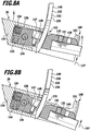
- the actuating lever 145 is formed as a latching lever 146, and it comprises a latching element 147 in the form of a latching tooth 148 (FIGS. Figures 8A and 8B ).
- the locking tooth 148 can cooperate with a further latching element 149 in the form of a detent rod 150 held on the handle arm 127 in order to lock or enable pivoting of the pivot lever 134 relative to the handle arm 127 about the pivot axis 135. For this reason, the locking lever 146 forms a blocking element 151, and the locking rod 150 forms a blocking element 152. Together they form a locking device 153 of the instrument 10th
- the pivot lever 134 can not be pivoted relative to the handle 127. This defines a blocking position of the locking device 153.
- the locking position is a basic position of the locking device 153, because the locking lever 146 is so by means of two elastic elements in the form of springs 154 and 155 which are arranged in an end-side receptacle 156 on the pivot lever 134, so for pivoting the pivot axis 144 is applied, so that it automatically engages with the locking rod 150.
- the locking device 153 prevents unintentional spreading of the implant 12 as a result of tissue pressure exerted on the clamp 37 and directed counter to the insertion counterpressure.
- the bias of the locking members 151 and 152 by the springs 154 and 155 relative to each other that when the implant 12 is slightly spread and the spinous processes 24 and 26 exert a force on the implant 12, the implant 12 is not back from the Sp Dahl ein is transferred back to the insertion position. Instead, it stays in the Spread position. This makes it easier for a surgeon to handle the instrumentation because the implant 12 can be gradually spread by the surgeon by applying force to the locking lever 146 and the surgeon can control, as it were, after each "spreading step" whether the implant 12 is sufficiently spread to provide secure support the spinous processes 24 and 26 to ensure relative to each other.
- the surgeon can control which position the handle arm 127 and the pivot lever 134 take relative to each other. From this, the surgeon can deduce how far the implant 12 has already been spread. It can be provided, in particular, that the scale 159 is calibrated such that the distance between the support surfaces 53 and 54 can be read from one another directly on the scale 159.
- a further display device 160 is arranged at the end on the pivot lever 134 and includes a scale 161. Based on the scale 161, the surgeon can determine with which operating force he force the locking lever 146 against the restoring force of the springs 154 and 155 to spread the implant 12. This actuation force is a measure of the support force introduced by the spinous processes 24 and 26 on the implant 12 and via the handle arm 127 and the pivot lever 134. Thus, the surgeon on the basis of the scale 161 also determine the support force.
- the scale 161 may be calibrated as well as the scale 159.
- the third handling device 22 of the instrumentation 10 is designed as a slide 162 which is mounted displaceably on the handle arm 127 parallel to the locking direction 105 and to the removal direction 951. It includes a first end 163 with an operator 164 disposed thereon for the operator. Opposite the first end 163, the slider 162 includes a second end 165. Approximately midway between the ends 163 and 165 and to the end 165, the slider 162 forms a first segment 166. Further, it forms a second segment 167. These are spaced apart and can the Handle arm 127 between them as well as the protruding from the shell 61 end of the adapter 106th
- the first segment comprises a front stop counter-abutment member 168
- the second segment comprises a front end counter-abutment member 169.
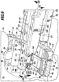
- the counter-stop members 168 and 169 are designated as such, because of them for removing the sleeve 61 and the adapter 106 from Implant 12 required counterforce on the implant 12 can be initiated. This can be done in a docking position of the slide 162. In the docking position, the counter-abutment element 168 abuts on the tension rod 50, in particular on the tensioning element 47. The counter-abutment element 169 can rest against the second implant component 29 in the landing position, in particular on the support segments 38 and 41 (FIG. FIG. 9 ).
- the handle arm 127 is connected to the adapter 106 by means of the detents 126 and 129. This allows the surgeon to hold the implant 12 on the grip element 131.
- the pivot lever 134 can be pivoted relative to the handle arm 127 so that the segments 136 and 137 to the wedge-shaped Slip projections 88 and 89.
- the Spreizanscheriana 90 and 140 and 91 and 141 may come into contact with each other.
- the peel stopper members 94 and 142 and 95 and 143 may come into abutment with each other.
- the slider 162 assumes a retracted position.
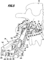
- the implant 12 is secured by the blocking elements 84 and 85 and the locking device 153 against unintentional spreading. It can ( FIG. 5 ) are introduced by the surgeon in the intervertebral space.
- the bone stop elements 75 and 76 and the insertion-side support elements 55, 56 and 57 form stop elements for the spinous processes 24 and 26 and thereby limit the insertion depth of the implant 12 in the intervertebral space.
- the pivot lever 134 By applying force to the locking lever 146 along the actuating direction 157, the pivot lever 134 can be pivoted relative to the handle arm 127.
- the Spreizanscheriana 90 and 140 and 91 and 141 cooperate to initiate an expanding force on the first implant component 28.
- the counterforce required for spreading is introduced by means of the gripping arm 127 via the adapter 106 onto the second implant component 29.
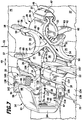
- the implant 12 is transferred from the insertion position into the spread position ( FIGS. 6 and 7 ).
- the spinous processes 24 and 26 are supported by means of the support surfaces 53 and 54 relative to each other.
- the surgeon can hold the handle arm 127 and thus coupled with this pivot lever 134 with only one hand and operate. With the other hand, he can move the slider 162 on the actuator 164 from the retracted position to the docking position. Abziehantschetti 94 and 142 and 95 and 143 cooperate to withdraw the sheath 61 from the implant 12. The counterforce is introduced via the counter stop elements 168 and 169 on the implant 12.
- the adapter 106 can be removed from the clamp 37 and from the locking element 99.
- the counterforce required for this can are also introduced via the counter-stop elements 168 and 169 on the implant 12, and the tensile force acts on the handle arm 127 at.
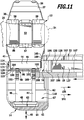
- the locking element 99 can be transferred from the release position into the locking position as described above and thus the implant 12 can be locked automatically (FIG. FIGS. 9 to 12 ).
- the clip 37 and the locking element 99 can be removed from the receptacle 113.
- the sheath 61 and the adapter 106 can be pulled together, held on the handle arm 127 and the pivot lever 134, from the implant 12 ( FIG. 13 ).
- the locked implant 12 remains in the spread position as intended between the spinous processes 24 and 26th
- the adapter 106 and the shell 61 can be released from the handle arm 127 and the pivot lever 134 and disposed of or reused.
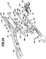
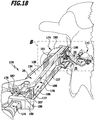
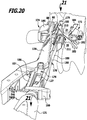
- a further embodiment of a surgical instrument not according to the invention is disclosed in US Pat FIG. 16 partially shown in exploded view and there occupied by the reference numeral 170. It comprises an implant 172, a fixing device 174, the holding device 16, a first handling device 176 which is functionally identical to the first handling device 18, the second handling device 20 and a third handling device 178.
- the instrumentation 170 is constructed in its individual components largely identical to the instrumentation 10, and for the same and equivalent features of the instruments 10 and 170, the same reference numerals are therefore used.
- the achievable with the instrumentation 10 benefits can also be achieved with the instrumentation 170. In the following, only the essential differences of the individual components of the instruments 10 and 170 will be discussed.
- the orientations of the support arms 31, 32, 34, 39, 40 and 42 along the spreading direction 51 are reversed in the case of the implant 172 educated. That is, the support arms 31 and 32 include insertion-side upper support members 179 and 180, respectively, and the support arm 34 includes an insertion-side lower support member 181.
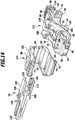
- the support arms 39 and 40 include body-side lower support members 182 and 183, respectively, and the support arm 42 includes a body-side upper support member 184 (FIGS. FIGS. 14 to 15B ).
- the support arms 31, 32, 34, 39, 40 and 42 thus form carriers of the support elements 179, 180, 181, 182, 183 and 184, respectively.
- the insertion-side upper support members 179 and 180 abut against the upper abutment members 70 and 71 of the fixing device 174, and the lower-end support member 181 abuts against the lower abutment members 73 and 74 of the fixing device 174.
- sheath 185 formed by fixation device 174 does not include bone stop members 75 and 76.
- the shell 185 does not include the blocking elements 84 and 85.
- the first segment 187 has a projection 193 in the direction of the second segment 188.
- the projection 193 forms two coupling elements 194 and 195 in the form of a driver stop 196 and a detent 197. These are respectively along the Verrieglungsraum 105 effective.
- the second segment 188 includes, at a second end 198 opposite the first end 189, a pair of counter-abutment members 199 and 200 separated from each other by a slit-shaped space 201.
- the second segment 188 comprises a projection 202, which forms a coupling element 203 in the form of a counter-stop 204 for the driver stop 196.
- the second segment 188 near the projection 202 comprises a coupling element 205 in the form of a projection 206 for the detent 197. Further, the second segment 188 forms a coupling element 207 in the form of a shoulder 208 which can cooperate with the actuator 290.
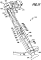
- the gripping arm 127 is first attached to the adapter 106 in the case of the instrument 170 and the pivot lever 134 is adapted to the sleeve 185 ( FIG. 17 in which the pivot lever 134 is not shown).
- the slider 186 assumes a retracted position, in which the counter-stop elements 192, 199 and 200 have a distance from the implant 172 and the detent 197 rests on the projection 206.
- the slider 186 is acted upon by the surgeon on the actuating member 190 with a force directed to the implant 172.
- the segments 187 and 188 couple by means of the locking lug 197 and the projection 206. This allows the counter-stop elements 199 and 200 in a formed between the support segments 38 and 41 of the implant 172 gap 209 (FIGS. FIGS. 15A and 15B ) introduce.
- the clamping elements 46 and 47 engage in the intermediate space 201 between the counter-stop elements 199 and 200 ( Figures 18 and 19 ).
- the second segment 188 with the counter-stop elements 199 and 200 can be arranged in a form-fitting manner, so that the support arms 39 and 40 can not be spread relative to the support arm 42 along the spreading direction 51.
- the counter-stop elements 199 and 200 form blocking elements 210 and 211, respectively, with which an undesired spreading of the implant 172 can be prevented.
- the position of the slider 186, in which the second segment 188 engages in the intermediate space 209, is referred to as the blocking position of the slider 186.
- the implant 172 can be spread after being introduced into the intervertebral space, the surgeon must act on the actuating member 190 with a force directed in the locking direction 105.
- the segments 187 and 188 couple by means of the driver stop 196 and the counter stop 204.
- the slide 186 can be converted back into the retracted position.
- the implant 172 can then be transferred from the insertion position into the expanded position in a manner corresponding to that explained above, such as the implant 12 (FIG. FIG. 20 ).
- the surgeon can re-apply the actuator 190 with a force directed to the implant 172.
- the second segment 188 with the counterstop elements 199 and 200 comes to bear against the second implant component 29 and is supported on it.
- the detent 197 can decouple from the projection 206.
- the first segment 187 can be displaced along the gripping arm 127 relative to the second segment 188 until the actuating member 190 comes to bear against the shoulder 208 ( FIG. 21 ). If this is the case, the first segment 187 abuts with the counter-stop element 192 on the clamping element 47.
- the shoulder 208 forms a driver stop 212, so that upon further application of the actuating member 190 with a force directed to the implant 172, a counter force for pulling off the sleeve 185 and the adapter 106 can be introduced thereon.
- the sheath 185 and the adapter 106 as described above for the case of the instrumentation 10, can be withdrawn from the implant 172 and also be automatically locked.
Landscapes
- Health & Medical Sciences (AREA)
- Orthopedic Medicine & Surgery (AREA)
- Life Sciences & Earth Sciences (AREA)
- Neurology (AREA)
- Surgery (AREA)
- Heart & Thoracic Surgery (AREA)
- Engineering & Computer Science (AREA)
- Biomedical Technology (AREA)
- Nuclear Medicine, Radiotherapy & Molecular Imaging (AREA)
- Medical Informatics (AREA)
- Molecular Biology (AREA)
- Animal Behavior & Ethology (AREA)
- General Health & Medical Sciences (AREA)
- Public Health (AREA)
- Veterinary Medicine (AREA)
- Prostheses (AREA)
- Surgical Instruments (AREA)
Description
- Die Erfindung betrifft ein chirurgisches Instrumentarium, umfassend ein Implantat zur gegenseitigen Abstützung eines oberen Dornfortsatzes eines ersten Wirbelkörpers mittels einer oberen Stützfläche und eines unteren Dornfortsatzes eines zweiten Wirbelkörpers mittels einer unteren Stützfläche, wobei das Implantat eine erste Implantatkomponente und eine relativ zu dieser entlang einer Spannrichtung beweglich ausgebildete zweite Implantatkomponente umfasst, um das Implantat ausgehend von einer Grundstellung in einer quer zur Spannrichtung ausgerichteten Spreizrichtung in eine Spreizstellung zu überführen, in der die obere Stützfläche und die untere Stützfläche einen größeren Abstand voneinander aufweisen als in der Grundstellung, und wobei das Implantat mindestens ein einbringseitiges oberes Stützelement und mindestens ein einbringseitiges unteres Stützelement zum einbringseitigen lateralen Abstützen des oberen Dornfortsatzes bzw. des unteren Dornfortsatzes in der Spreizstellung des Implantats umfasst.
- Außerdem wird ein chirurgisches Instrumentarium mit einer Handhabungseinrichtung zum Halten eines Implantates beschrieben. Ein Implantat der eingangs genannten Art ist in der
DE 20 2008 009 344 U1 beschrieben. Es kann in der Grundstellung durch einen unilateralen Zugang von einer Einbringseite in den Körper eingebracht werden und im Zwischenwirbelraum zwischen den Dornfortsätzen positioniert werden. Durch Überführen des Implantates von der Grundstellung in die Spreizstellung vergrößern die Stützflächen ihren Abstand voneinander, so dass die auf den Stützflächen ruhenden Dornfortsätze mehr oder weniger auseinander geschoben werden können, zur Stabilisierung benachbarter Wirbelkörper relativ zueinander. Zur lateralen Stabilisierung des oberen und des unteren Wirbelkörpers umfasst das Implantat mindestens ein oberes Stützelement sowie ein unteres Stützelement, die jeweils einbringseitig, d.h. von der Seite, von der das Implantat in den Körper eingebracht wird, die Dornfortsätze abstützen können. Die Stützelemente werden ebenfalls beim Überführen des Implantates von der Grundstellung in die Spreizstellung relativ zueinander gespreizt, wobei sie sich jeweils ausgehend vom Zwischenwirbelraum den Dornfortsätzen annähern. In entsprechender Weise kann das Implantat mindestens ein oberes Stützelement sowie mindestens ein unteres Stützelement umfassen, die körperseitig lateral den oberen bzw. den unteren Dornfortsatz abstützen können, d.h. von der der Einbringseite abgewandten Seite der Dornfortsätze. - Aufgabe der vorliegenden Erfindung ist es, ein gattungsgemäßes chirurgisches Instrumentarium so weiterzubilden, dass es eine verbesserte Handhabbarkeit aufweist.
- Diese Aufgabe wird bei einem chirurgischen Instrumentarium der eingangs genannten Art erfindungsgemäß dadurch gelöst, dass das Instrumentarium eine Fixiereinrichtung für das Implantat umfasst zum Spreizen des mindestens einen einbringseitigen oberen Stützelementes und des mindestens einen einbringseitigen unteren Stützelementes relativ zueinander entlang der Spreizrichtung, mittels welcher Fixiereinrichtung das Implantat ausgehend von der Grundstellung in eine Einbringstellung bringbar ist, in der das mindestens eine einbringseitige obere Stützelement und das mindestens eine einbringseitige untere Stützelement einen größeren Abstand relativ zueinander aufweisen als in der Grundstellung, und aus der das Implantat durch Bewegen der zweiten Implantatkomponente relativ zur ersten Implantatkomponente entlang der Spannrichtung in die Spreizstellung überführbar ist. Vorteilhafte Weiterbildungen der Erfindung sind Gegenstand der abhängigen Ansprüche. Mittels der Fixiereinrichtung kann das Implantat ausgehend von einer Grundstellung in eine Einbringstellung gebracht werden. Das mindestens eine einbringseitige obere Stützelement und das mindestens eine einbringseitige untere Stützelement geraten dadurch relativ zueinander in einen Abstand, der größer ist als ihr Abstand voneinander in der Grundstellung des Implantates. Bei geeigneter Dimensionierung der Fixiereinrichtung kann ein Abstand zwischen einem oberen Stützelement und einem unteren Stützelement erzielt werden, der größer ist als der Abstand des oberen und des unteren Dornfortsatzes voneinander. Dies führt dazu, dass bereits beim Einbringen des Implantates in der Einbringstellung in den Zwischenwirbelraum das mindestens eine einbringseitige obere Stützelement zur Anlage an den oberen Dornfortsatz geraten kann und das mindestens eine einbringseitige untere Stützelement zur Anlage an den unteren Dornfortsatz, ohne dass hierfür ein Überführen des Implantates in die Spreizstellung erforderlich ist. Die Stützelemente bilden somit Anschläge für die Dornfortsätze aus, so dass die maximale Einbringtiefe des Implantates in den Zwischenwirbelraum dadurch begrenzt ist. Dies erleichtert einem Operateur die Handhabung des Implantates, und die Stützelemente können ungefähr an derjenigen Stelle zur Anlage an die Dornfortsätze geraten, die sie in der Spreizstellung des Implantates ebenfalls einnehmen können. Dies bedeutet, dass sich das Implantat relativ zu den Dornfortsätzen verbessert positionieren lässt. Darüber hinaus wird sichergestellt, dass ein Operateur das Implantat nicht zu tief in den Zwischenwirbelraum einbringt, es kann daher weniger invasiv gearbeitet werden, und eine Verletzungsgefahr für den Patienten ist verringerbar.
- Die Fixiereinrichtung umfasst vorzugsweise eine Aufnahme, in der das Implantat, zumindest teilweise, gehalten ist. Ergänzend oder alternativ kann das Implantat eine Aufnahme umfassen, in der die Fixiereinrichtung, zumindest teilweise, gehalten ist. Die Fixiereinrichtung kann dadurch mit dem Implantat verbunden werden, damit dieses von der Grundstellung in die Einbringstellung gebracht werden kann.
- Günstig ist es, wenn die Fixiereinrichtung mindestens einen entgegen der Spreizrichtung wirksamen ersten oberen Anschlag für das mindestens eine einbringseitige obere Stützelement oder einen dieses umfassenden Träger umfasst oder ausbildet und/oder wenn die Fixiereinrichtung mindestens einen entgegen der Spreizrichtung wirksamen ersten unteren Anschlag für das mindestens eine einbringseitige untere Stützelement oder einen dieses umfassenden Träger umfasst oder ausbildet. Dies gibt eine einfache konstruktive Möglichkeit, das obere Stützelement und das untere Stützelement gegeneinander zu spreizen, um ihren Abstand voneinander in der Einbringstellung des Implantates im Vergleich zur Grundstellung des Implantates zu vergrößern.
- Von Vorteil ist es, wenn das mindestens eine einbringseitige obere Stützelement oder der es umfassende Träger in der Einbringstellung des Implantates an dem mindestens einen ersten oberen Anschlag anliegt und/oder wenn das mindestens eine einbringseitige untere Stützelement oder der es umfassende Träger in der Einbringstellung des Implantates an dem mindestens einen ersten unteren Anschlag anliegt. Dadurch lässt sich eine zuverlässige Spreizung des oberen Stützelementes und des unteren Stützelementes relativ zueinander sicherstellen. Der erste obere und/oder der erste untere Anschlag umfassen hierfür jeweils eine Anlagefläche für das jeweilige Spreizelement oder den jeweiligen Träger.
- Günstig ist es, wenn die Fixiereinrichtung mindestens einen in der Spreizrichtung wirksamen zweiten oberen Anschlag für das mindestens eine einbringseitige obere Stützelement oder einen dieses umfassenden Träger umfasst oder ausbildet und/oder wenn die Fixiereinrichtung mindestens einen in der Spreizrichtung wirksamen zweiten unteren Anschlag für das mindestens eine einbringseitige untere Stützelement oder einen dieses umfassenden Träger umfasst oder ausbildet. Dadurch lässt sich auf einfache konstruktive Weise sicherstellen, dass in der Einbringstellung das obere und das untere Stützelement längs der Spreizrichtung einen maximalen Abstand, der durch den Abstand des zweiten oberen Anschlages und des zweiten unteren Anschlages voneinander gegeben ist, nicht überschreiten. Dies ermöglicht es, eine Beschädigung des Implantates in der Einbringstellung zu vermeiden.
- Von Vorteil ist es, wenn das mindestens eine einbringseitige obere Stützelement oder der es umfassende Träger in der Einbringstellung des Implantates an dem mindestens einen zweiten oberen Anschlag anliegt und/oder wenn das mindestens eine einbringseitige untere Stützelement oder der es umfassende Träger in der Einbringstellung des Implantates an dem mindestens einen zweiten unteren Anschlag anliegt. Dadurch kann auf zuverlässige Weise sichergestellt werden, dass das obere Stützelement und das untere Stützelement entlang der Spreizrichtung nicht so weit gegeneinander gespreizt werden, dass das Implantat beschädigt wird. Der zweite obere und/oder der zweite untere Anschlag umfassen hierfür jeweils eine Anlagefläche für das jeweilige Stützelement oder den jeweiligen Träger.
- Insbesondere kann vorgesehen sein, dass in der Einbringstellung des Implantates das mindestens eine einbringseitige obere Stützelement formschlüssig zwischen dem mindestens einen ersten oberen Anschlag und dem mindestens einen zweiten oberen Anschlag angeordnet ist und dass das mindestens eine einbringseitige untere Stützelement formschlüssig zwischen dem mindestens einen ersten unteren Anschlag und dem mindestens einen zweiten unteren Anschlag angeordnet ist, um eine zuverlässige Fixierung des Implantates sicherzustellen.
- Günstig ist es, wenn die Fixiereinrichtung mindestens ein einbringseitiges oberes Knochenanschlagelement für den oberen Dornfortsatz umfasst oder ausbildet und/oder wenn die Fixiereinrichtung mindestens ein einbringseitiges unteres Knochenanschlagelement für den unteren Dornfortsatz umfasst oder ausbildet. Dies erleichtert die Handhabung des Implantates. Beim Einbringen des Implantates in den Zwischenwirbelraum kann sich dieses nicht nur mittels des oberen und des unteren Stützelementes an den oberen bzw. unteren Dornfortsatz anlegen, sondern auch mittels der Fixiereinrichtung. Dadurch ist eine zuverlässigere Positionierung des Implantates relativ zu den Dornfortsätzen erzielbar.
- In der Einbringstellung des Implantates sind das obere Knochenanschlagelement und das untere Knochenanschlagelement relativ zueinander günstigerweise weiter beabstandet als das einbringseitige obere Stützelement und das einbringseitige untere Stützelement, um das Hantieren mit dem Implantat im Zwischenwirbelraum zu erleichtern.
- Es kann vorgesehen sein, dass die erste Implantatkomponente das mindestens eine einbringseitige obere Stützelement und das mindestens eine einbringseitige untere Stützelement umfasst. Dies hat sich in der Praxis als vorteilhaft für eine einfachere Konstruktion des Implantates erwiesen.
- Alternativ oder ergänzend kann vorgesehen sein, dass die zweite Implantatkomponente mindestens ein einbringseitiges oberes Stützelement und/oder mindestens ein einbringseitiges unteres Stützelement umfasst.
- Vorzugsweise umfasst das Implantat mindestens ein körperseitiges oberes Stützelement und mindestens ein körperseitiges unteres Stützelement zum körperseitigen lateralen Abstützen des oberen Dornfortsatzes bzw. des unteren Dornfortsatzes in der Spreizstellung des Implantates. Wie bereits erwähnt, wird "körperseitig" vorliegend als diejenige laterale Seite der Dornfortsätze angesehen, die derjenigen lateralen Seite der Dornfortsätze abgewandt ist, auf die gerichtet das Implantat in den Körper eingebracht wird. Das obere Stützelement und das untere Stützelement ermöglichen körperseitig ein seitliches Abstützen des oberen bzw. des unteren Dornfortsatzes und dadurch auch eine zuverlässigere Abstützung derselben relativ zueinander.
- Es kann vorgesehen sein, dass die zweite Implantatkomponente das mindestens eine körperseitige obere Stützelement und das mindestens eine körperseitige untere Stützelement umfasst. Dies hat sich in der Praxis als vorteilhaft für eine einfachere konstruktive Ausgestaltung des Implantates herausgestellt.
- Alternativ oder ergänzend kann vorgesehen sein, dass die erste Implantatkomponente mindestens ein körperseitiges oberes Stützelement und/oder mindestens ein körperseitiges unteres Stützelement umfasst.
- Bevorzugt umfasst das chirurgische Instrumentarium eine Kopplungseinrichtung mit mindestens einem mit einem einbringseitigen Stützelement gekoppelten ersten Kopplungselement sowie mit mindestens einem mit einem körperseitigen Stützelement gekoppelten zweiten Kopplungselement, das in der Einbringstellung des Implantates mit dem mindestens einen ersten Kopplungselement zusammenwirkt zur Verringerung des Abstandes des mindestens einen körperseitigen oberen Stützelementes und des mindestens einen körperseitigen unteren Stützelementes voneinander relativ zu deren Abstand voneinander in der Grundstellung des Implantates. In der Einbringstellung des Implantates weisen das mindestens eine einbringseitige obere Stützelement und das mindestens eine einbringseitige untere Stützelement voneinander einen größeren Abstand auf als in der Grundstellung des Implantates. Dies kann mittels der Fixiereinrichtung sichergestellt werden. Bei der vorliegenden Ausführungsform ist es mittels der zusätzlichen Kopplungseinrichtung weiter möglich, den Abstand des mindestens einen körperseitigen oberen Stützelementes und des mindestens einen körperseitigen unteren Stützelementes voneinander in der Einbringstellung des Implantates relativ zu deren Abstand voneinander in der Grundstellung des Implantates zu verringern. Dies gibt die Möglichkeit, die Einbringhöhe des Implantates mittels der Fixiereinrichtung und der Kopplungseinrichtung zu verringern. Dadurch wird einem Operateur das Einbringen des Implantates in den Zwischenwirbelraum erleichtert. Außerdem ist die Gefahr verringerbar, dass der Operateur beim Einbringen des Implantates unerwünschterweise an den Dornfortsätzen anstößt oder an anderen Körperstrukturen, wie z.B. Bändern, Sehnen oder Muskeln. Dies erleichtert die Handhabung des Implantates erheblich. Um ein einbringseitiges Stützelement mit einem körperseitigen Stützelement zu koppeln, umfasst die Kopplungseinrichtung das mindestens eine erste Kopplungselement und das mindestens eine zweite Kopplungselement, die in der Einbringstellung des Implantates zusammenwirken.
- Das erste und/oder das zweite Kopplungselement kann mit dem einbringseitigen bzw. dem körperseitigen Stützelement beispielsweise verbunden sein, insbesondere einstückig, um mit ihm gekoppelt zu sein.
- Günstig ist es, wenn das Implantat die Kopplungseinrichtung umfasst oder ausbildet, denn dies erlaubt es, dem chirurgischen Instrumentarium eine einfachere Konstruktion zu verleihen.
- Es kann insbesondere vorgesehen sein, dass die erste Implantatkomponente das mindestens eine erste Kopplungselement umfasst und dass die mindestens eine zweite Implantatkomponente das mindestens eine zweite Kopplungselement umfasst.
- Vorzugsweise umfasst die Kopplungseinrichtung ein mit einem einbringseitigen oberen Stützelement gekoppeltes erstes Kopplungselement und ein mit diesem zusammenwirkendes und mit einem körperseitigen unteren Stützelement gekoppeltes zweites Kopplungselement. Entlang der Spreizrichtung ist in der Einbringstellung des Implantates die Wirkung der Fixiereinrichtung zusammen mit der Kopplungseinrichtung in Bezug auf das einbringseitige obere Stützelement und das körperseitige untere Stützelement gegenläufig. Je weiter das einbringseitige obere Stützelement unter der Wirkung der Fixiereinrichtung relativ zu einem einbringseitigen unteren Stützelement gespreizt wird, desto näher gelangt das körperseitige untere Stützelement an ein körperseitiges oberes Stützelement. Es hat sich in der Praxis gezeigt, dass die Kopplungseinrichtung bei dieser Ausführungsform eine einfache Konstruktion aufweisen kann und eine zuverlässige Funktion der Kopplungseinrichtung sichergestellt werden kann.
- In entsprechender Weise ist es zur Erzielung desselben Vorteils günstig, wenn die Kopplungseinrichtung ein mit einem einbringseitigen unteren Stützelement gekoppeltes erstes Kopplungselement und ein mit diesem zusammenwirkendes und mit einem körperseitigen oberen Stützelement gekoppeltes zweites Kopplungselement umfasst.
- Vorzugsweise bilden das mindestens eine erste Kopplungselement und/oder das mindestens eine zweite Kopplungselement zumindest teilweise eine Stützfläche für einen Dornfortsatz aus. Das erste und/oder das zweite Kopplungselement können dadurch eine zusätzliche Funktion ausüben. Dies erlaubt es, dem Implantat eine kompaktere Bauform zu verleihen.
- Günstig ist es, wenn die Kopplungseinrichtung ein erstes Kopplungselement für ein einbringseitiges oberes Stützelement und ein erstes Kopplungselement für ein einbringseitiges unteres Stützelement umfasst, die mittels der Fixiereinrichtung in der Einbringstellung des Implantates längs der Spreizrichtung weiter relativ zueinander gespreizt sind als in der Grundstellung des Implantates. Dadurch ist die Möglichkeit gegeben, zwei zweite Kopplungselemente, die mit den ersten Kopplungselementen zusammenwirken, längs der Spreizrichtung einander anzunähern, beispielsweise dann, wenn sich jeweils ein erstes Kopplungselement und ein zweites Kopplungselement längs der Spreizrichtung gegenseitig aufeinander abstützen. Wenn von den zweiten Kopplungselementen eines mit einem körperseitigen oberen Stützelement gekoppelt ist und eines mit einem körperseitigen unteren Stützelement, ermöglicht dies, das körperseitige obere und das körperseitige untere Stützelement längs der Spreizrichtung einander anzunähern.
- Die Spreizung der ersten Kopplungselemente relativ zueinander wird mittels der Fixiereinrichtung erzielt, beispielsweise unter der Wirkung des vorstehend erwähnten ersten oberen Anschlags für ein einbringseitiges oberes Stützelement sowie des dem ersten unteren Anschlags für ein einbringseitiges unteres Stützelement.
- Insbesondere sind die zwei ersten Kopplungselemente relativ zueinander längs der Spreizrichtung vorgespannt.
- Vorzugsweise sind das mindestens eine erste Kopplungselement und/oder das mindestens eine zweite Kopplungselement elastisch verformbar ausgebildet, denn dadurch kann eine zuverlässigere Funktion der Kopplungseinrichtung und des Implantates sichergestellt werden.
- Bei einer vorteilhaften Ausgestaltung des Instrumentariums hat es sich als günstig erwiesen, wenn das mindestens eine erste Kopplungselement als ein das einbringseitige Stützelement an einem freien Ende umfassender erster Träger ausgebildet ist, der ein längs der Spreizrichtung wirksames Aufgleitelement für das mindestens eine zweite Kopplungselement ausbildet, und/oder wenn das mindestens eine zweite Kopplungselement als ein das körperseitige Stützelement an einem freien Ende umfassender zweiter Träger ausgebildet ist, der ein längs der Spreizrichtung wirksames Aufgleitelement für das mindestens eine erste Kopplungselement ausbildet. Beim Überführen des Implantates von der Einbringstellung in die Spreizstellung können ein erstes Kopplungselement und ein zweites Kopplungselement jeweils aneinander aufgleiten und sich gegenseitig abstützen, wobei sie für das jeweils andere Kopplungselement ein Aufgleitelement ausbilden. Dieses Aufgleiten ist längs der Spreizrichtung wirksam. Das einbringseitige Stützelement und das körperseitige Stützelement, sei es für den oberen Dornfortsatz oder für den unteren Dornfortsatz, können dadurch jeweils entlang der Spreizrichtung bewegt werden, bis sie ihre Position in der Spreizstellung des Implantates einnehmen können. Dies ermöglicht eine zuverlässige Funktion des Implantates bei einer zugleich einfachen Konstruktion desselben.
- Von Vorteil ist es, wenn das chirurgische Instrumentarium mindestens ein Blockierelement umfasst zum Verhindern einer Bewegung eines körperseitigen Stützelementes entlang der Spreizrichtung in der Einbringstellung des Implantates. Dadurch kann verhindert werden, dass das mindestens eine körperseitige obere Stützelement und das mindestens eine körperseitige untere Stützelement nicht unerwünschterweise in der Einbringstellung des Implantates ihren Abstand voneinander vergrößern. Dadurch kann die Einbringhöhe des Implantates vor dessen Überführen in die Spreizstellung konstant gehalten werden. Eine Gefahr, dass ein körperseitiges Stützelement unerwünschterweise einen Dornfortsatz oder eine andere Körperstruktur beim Einbringen des Implantates kontaktiert, wird dadurch verringert.
- Eine einfache konstruktive Ausgestaltung des Instrumentariums wird dadurch ermöglicht, dass das mindestens eine Blockierelement einen mit dem körperseitigen Stützelement oder mit einem dieses umfassenden Träger zusammenwirkenden Anschlag umfasst oder ausbildet.
- Es kann insbesondere vorgesehen sein, dass das chirurgische Instrumentarium mehr als nur ein Blockierelement umfasst, wobei mittels jedes Blockierelementes eine Bewegung eines körperseitigen Stützelementes längs der Spreizrichtung verhinderbar ist.
- Eine besonders einfache konstruktive Ausgestaltung des Instrumentariums wird ermöglicht, wenn die Fixiereinrichtung das mindestens eine Blockierelement umfasst oder ausbildet.
- Es kann auch vorgesehen sein, dass mindestens ein Blockierelement in der Einbringstellung des Implantates an das körperseitige Stützelement oder an einen dieses umfassenden Träger anlegbar und vor dem Überführen des Implantates von der Einbringstellung in die Spreizstellung vom Stützelement oder vom Träger entfernbar ist. Das mindestens eine Blockierelement wird nur solange benötigt, bis ein Operateur das Implantat nach dem Einbringen in den Körper von der Einbringstellung in die Spreizstellung überführen möchte. Bei dieser Ausgestaltung kann das mindestens eine Blockierelement zur Verhinderung der Bewegung des Stützelementes an das Stützelement oder an den Träger angelegt werden. Dies definiert beispielsweise eine Blockierstellung des mindestens einen Blockierelementes. Möchte der Operateur das Implantat in die Spreizstellung überführen, kann er das mindestens eine Blockierelement vom Stützelement oder vom Träger entfernen und in eine dadurch definierte zurückgezogene Stellung überführen.
- Von Vorteil ist es, wenn das mindestens eine Blockierelement in einen zwischen einem ein körperseitiges oberes Stützelement umfassenden ersten Träger und einem ein körperseitiges unteres Stützelement umfassenden zweiten Träger, die beim Überführen des Implantates von der Einbringstellung in die Spreizstellung längs der Spreizrichtung relativ zueinander spreizbar sind, gebildeten Zwischenraum einführbar und insbesondere formschlüssig einführbar ist. Dadurch kann auf konstruktive Weise eine zuverlässige Sicherung der Träger gegen eine Spreizbewegung relativ zueinander sichergestellt werden. Damit lässt sich auch eine Bewegung des körperseitigen oberen und des körperseitigen unteren Stützelementes relativ zueinander längs der Spreizrichtung verhindern.
- Von Vorteil ist es, wenn das chirurgische Instrumentarium mindestens ein Schutzelement für das Implantat umfasst, denn dadurch kann es gegen Beschädigung gesichert werden.
- Vorzugsweise ist das mindestens eine Schutzelement als eine das Implantat einbringseitig zumindest teilweise umgebende Hülle ausgebildet. Dadurch ist die Möglichkeit gegeben, das Implantat insbesondere auf der Einbringseite zu schützen, an welcher ein Operateur typischerweise mit einer Handhabungseinrichtung für das Implantat oder dergleichen angreift. An der Körperseite des Implantates, d.h. demjenigen Bereich des Implantates, der durch den Zwischenwirbelraum hindurch zwischen die Dornfortsätze eingeführt wird, wird das Implantat demgegenüber von der Hülle vorzugsweise nicht umgeben. Dadurch wird zum Einbringen des Implantates in den Zwischenwirbelraum nur wenig Platz beansprucht.
- Vorteilhafterweise wird die Hülle ungefähr die Hälfte des Implantates, bezogen auf dessen Erstreckung längs der Spannrichtung, umgeben, um einen zuverlässigen Schutz des Implantates sicherzustellen.
- Es kann vorgesehen sein, dass die Hülle die zweite Implantatkomponente zumindest teilweise umgibt. Diese ist dann z.B. einbringseitig angeordnet, während die erste Implantatkomponente körperseitig angeordnet ist und zuerst in den Körper eingebracht wird.
- Vorzugsweise umfasst die Fixiereinrichtung das mindestens eine Schutzelement oder bildet dieses aus. Dies ermöglicht es, dem Instrumentarium eine besonders einfache und kompakte Bauform zu verleihen.
- Von Vorteil ist es, wenn die Fixiereinrichtung einen im Wesentlichen U-förmigen Querschnitt aufweist. Dadurch kann die Fixiereinrichtung die Gestalt einer Klammer in Form eines großen U verliehen werden. Dies gibt die Möglichkeit, ein Schutzelement für das Implantat zu bilden, um dieses von drei Seiten zu schützen, wenn die Fixiereinrichtung am Implantat angebracht ist.
- Zur Ausgestaltung des U-förmigen Querschnittes kann die Fixiereinrichtung zwei die Schenkel des U bildende voneinander beabstandete Segmente umfassen. Die Segmente können an einem ihrer jeweiligen Enden mittels eines Verbindungssegmentes verbunden sein. An ihren jeweiligen freien Enden können das erste und das zweite Segment den vorstehend beschriebenen mindestens einem ersten oberen Anschlag, den mindestens einen zweiten oberen Anschlag sowie ein Knochenanschlagelement umfassen oder ausbilden beziehungsweise den mindestens einen ersten unteren Anschlag, den mindestens einen zweiten unteren Anschlag sowie ein Knochenanschlagelement umfassen oder ausbilden. Am Verbindungselement kann eine Aufnahme für eine und insbesondere die erste Implantatkomponente gebildet sein. In die Aufnahme kann die Implantatkomponente zumindest teilweise eingeführt und so die Fixiereinrichtung am Implantat angebracht werden.
- Günstig ist es, wenn die Fixiereinrichtung einstückig ausgebildet ist, denn dies vereinfacht ihre Herstellung.
- Vorzugsweise ist die Fixiereinrichtung aus einem Kunststoffmaterial gefertigt, denn dies ermöglicht eine kostengünstige Herstellung der Fixiereinrichtung.
- Die Fixiereinrichtung kann insbesondere aus einem verformbaren Material gefertigt sein. Dies gibt beispielsweise die Möglichkeit, die Fixiereinrichtung auf einfachere Weise am Implantat anzubringen oder von diesem zu lösen.
- Günstig ist es, wenn die Fixiereinrichtung aus einem elastisch verformbaren Material gefertigt ist. Dies ist insbesondere dann von Vorteil, wenn die Fixiereinrichtung am Implantat anzubringen ist und dabei zu verformen ist. Eine Beschädigung der Fixiereinrichtung kann dadurch verhindert werden.
- Es kann vorgesehen sein, dass die Fixiereinrichtung am Implantat vormontiert ist. Das erleichtert die Handhabung des Instrumentariums, da ein Operateur die Fixiereinrichtung nicht vor dem Einbringen am Implantat anbringen muss.
- Bevorzugt ist eine am Implantat montierte Fixiereinrichtung von diesem lösbar. Nach dem Überführen des Implantates von der Einbringstellung in die Spreizstellung wird die Fixiereinrichtung nicht weiter benötigt, da das Implantat bestimmungsgemäß an den Dornfortsätzen anliegt. Bei dieser Ausführungsform ist somit die Möglichkeit gegeben, die Fixiereinrichtung nach dem Einsetzen des Implantates aus dem Körper zu entfernen.
- Alternativ oder ergänzend kann vorgesehen sein, dass die Fixiereinrichtung aus einem resorbierbaren Material hergestellt ist, und es ist möglich, dass sie nach dem Einsetzen des Implantates in den Zwischenwirbelraum im Körper verbleibt.
- Von Vorteil ist es, wenn die Fixiereinrichtung mindestens ein erstes Abziehlagerelement zum Abziehen der Fixiereinrichtung vom Implantat ausbildet, denn dies gibt auf konstruktiv einfache Weise die Möglichkeit, die Fixiereinrichtung vom Implantat zu lösen. An dem ersten Abziehlagerelement kann eine Handhabungseinrichtung des Instrumentariums angreifen, um die Fixiereinrichtung vom Implantat zu lösen.
- Bevorzugt umfasst die Fixiereinrichtung mindestens ein in einer quer zur Spannrichtung orientierten Abziehrichtung wirksames Abziehanschlagelement oder bildet dieses aus. Dies erlaubt es, die Fixiereinrichtung quer zur Spannrichtung, ohne die Position der beiden Implantatkomponenten relativ zueinander zu beeinflussen, vom Implantat abzuziehen. Die Abziehrichtung kann insbesondere senkrecht zur Spannrichtung ausgerichtet sein.
- Günstig ist es, wenn die Abziehrichtung quer und insbesondere senkrecht zur Spreizrichtung ausgerichtet ist. Dies gibt die Möglichkeit, die Fixiereinrichtung vom Implantat abzuziehen, ohne auf den oberen und/oder den unteren Dornfortsatz unerwünschterweise eine diese auseinander treibende Kraft auszuüben.
- Als günstig hat es sich erwiesen, wenn die Fixiereinrichtung ein erstes Spreizlagerelement zum Überführen des Implantates von der Einbringstellung in die Spreizstellung umfasst oder ausbildet. Dies erlaubt es, dem Instrumentarium eine kompaktere Bauform zu verleihen. An dem ersten Spreizlagerelement kann eine längs der Spannrichtung wirksame Spreizkraft zum Spreizen des Implantates angreifen.
- Vorzugsweise umfasst die Fixiereinrichtung mindestens ein längs der Spannrichtung wirksames Spreizanschlagelement oder bildet dieses aus. Dadurch ist auf einfache konstruktive Weise die Möglichkeit gegeben, dass die Fixiereinrichtung ein Spreizlagerelement ausbildet. An diesem kann beispielsweise eine Handhabungseinrichtung des Instrumentariums zum Spreizen des Implantates angreifen.
- Günstig ist es, wenn das mindestens eine Spreizanschlagelement mit einer von der Fixiereinrichtung gebildeten Aufnahme gekoppelt ist, in der eine und vorzugsweise die erste Implantatkomponente gehalten ist. Das Spreizanschlagelement ist mittels der Aufnahme beispielsweise kraft- und/oder formschlüssig gekoppelt. Dadurch kann eine am Spreizanschlagelement angreifende Spreizkraft auf die Aufnahme und damit auf die darin gehaltene Implantatkomponente, insbesondere die erste Implantatkomponente, übertragen werden. Hierfür umfasst die Aufnahme bevorzugt einen längs der Spannrichtung wirksamen Anschlag für die Implantatkomponente.
- Vorzugsweise bildet die vorstehend genannte Hülle ein Koppelelement, dass das erste Spreizlagerelement mit der Aufnahme koppelt, wobei diese und das mindestens eine Spreizlagerelement von der Hülle ausgebildet oder umfasst werden.
- Vorteilhafterweise weist das chirurgische Instrumentarium eine Halteeinrichtung auf, die eine Aufnahme für eine Implantatkomponente und insbesondere die zweite Implantatkomponente umfasst, in der diese teilweise gehalten ist. Mittels der Halteeinrichtung kann die Implantatkomponente und insbesondere die zweite Implantatkomponente und damit auch das Implantat gehalten werden.
- Alternativ oder ergänzend kann vorgesehen sein, dass das Implantat und vorzugsweise die zweite Implantatkomponente eine Aufnahme umfasst oder ausbildet, in der die Halteeinrichtung gehalten ist.
- Bevorzugt bildet die Halteeinrichtung ein zweites Spreizlagerelement zum Überführen des Implantates von der Einbringstellung in die Spreizstellung. Greift an der Halteeinrichtung eine längs der Spannrichtung wirksame Spreizkraft an, kann dadurch das Implantat in die Spreizstellung überführt werden. Die hierfür erforderliche Gegenkraft kann, wie vorstehend erwähnt, an der Fixiereinrichtung angreifen.
- Von Vorteil ist es, wenn die Fixiereinrichtung ein Führungselement für die Halteeinrichtung beim Überführen des Implantates von der Einbringstellung in die Spreizstellung ausbildet. Dadurch ist die Möglichkeit gegeben, die Halteeinrichtung in einer klar definierten Richtung relativ zur Fixiereinrichtung zu bewegen und dadurch das Implantat zuverlässig in die Spreizstellung zu überführen.
- Grundsätzlich ist es möglich, dass ein Operateur sich allein der Halteeinrichtung bedient, um das Implantat in den Körper einzubringen. Hierfür kann die Halteeinrichtung beispielsweise ein Griffelement umfassen oder ausbilden.
- Vorzugsweise umfasst die Halteeinrichtung allerdings eine Verbindungseinrichtung zum Verbinden mit einer ersten Handhabungseinrichtung des chirurgischen Instrumentariums für das Implantat. Dies gibt die Möglichkeit, die Halteeinrichtung mit der ersten Handhabungseinrichtung zu verbinden. Die Halteeinrichtung kann dadurch gewissermaßen ein Zwischenstück ausbilden zwischen der Handhabungseinrichtung und dem Implantat. Dies ist von Vorteil, wenn die Halteeinrichtung ein Wegwerfteil ist, das mit nur einem Implantat zum Einsatz kommt, wohingegen die erste Handhabungseinrichtung ein mehrfach einzusetzendes Werkzeug ist.
- Günstig ist es, wenn die Verbindungseinrichtung als Rasteinrichtung ausgebildet ist, denn dadurch ist die Möglichkeit gegeben, die Handhabungseinrichtung auf einfache Weise mit der Halteeinrichtung zu verbinden. Die Rastverbindung zwischen der Halteeinrichtung und der Handhabungseinrichtung kann lösbar sein.
- Vorzugsweise weist das Implantat eine ein Verriegelungselement umfassende Verriegelungseinrichtung auf, welches Verriegelungselement in der Spreizstellung des Implantates von einer Freigabestellung, in der die zweite Implantatkomponente relativ zur ersten Implantatkomponente entlang der Spannrichtung beweglich ist, in einer quer zur Spannrichtung ausgerichteten Verriegelungsrichtung in eine Verriegelungsstellung überführbar ist, in der die zweite Implantatkomponente gegen eine der Spannrichtung entgegen gerichtete Bewegung an der ersten Implantatkomponente verriegelt ist. Mittels des Verriegelungselementes kann sichergestellt werden, dass sich die zwei Implantatkomponenten in der Spreizstellung des Implantates nicht relativ zueinander längs der Spannrichtung bewegen. Dadurch behält das Implantat nach dem Einsetzen in den Körper die Spreizstellung bei und kann zum zuverlässigen Abstützen der Dornfortsätze relativ zueinander wirksam werden.
- Vorteilhafterweise ist das Verriegelungselement zusammen mit einem von der zweiten Implantatkomponente umfassten und mit dem Verriegelungselement zum Verriegeln des Implantates zusammenwirkenden Fixierelement in der Aufnahme gehalten. Dadurch kann eine zuverlässige Relativpositionierung des Verriegelungselementes und des Fixierelementes zueinander sichergestellt werden. Dies ist sowohl zum Überführen des Verriegelungselementes von der Freigabestellung in die Verriegelungsstellung von Vorteil als auch beim Spreizen des Implantates.
- Vorzugsweise umfasst die Halteeinrichtung mindestens ein erstes Kopplungsglied oder bildet dieses aus, das mit mindestens einem vom Verriegelungselement umfassten oder ausgebildeten zweiten Kopplungsglied zum Überführen des Verriegelungselementes von der Freigabestellung in die Verriegelungsstellung zusammenwirkt. Dadurch kann die Halteeinrichtung über die Funktion zum Halten und gegebenenfalls auch zum Spreizen des Implantates hinaus eine weitere Funktion ausüben. Das mindestens eine erste Kopplungsglied koppelt mit dem mindestens einen zweiten Kopplungsglied des Verriegelungselementes, so dass dieses mittels der Halteeinrichtung in die Verriegelungsstellung überführt werden kann. Dies erleichtert die Handhabung des Instrumentariums.
- Bei einer einfachen konstruktiven Ausgestaltung des Instrumentariums ist das mindestens eine erste Kopplungsglied als längs der Verriegelungsrichtung wirksamer Mitnehmeranschlag für das Verriegelungselement ausgebildet. Das mindestens eine zweite Kopplungsglied ist in entsprechender Weise als ein Anschlag ausgebildet, der mit dem Mitnehmeranschlag zusammenwirkt. Wird die Halteeinrichtung mit einer in der Verriegelungsrichtung wirkenden Kraft beaufschlagt, koppeln die Kopplungsglieder miteinander, so dass das Verriegelungselement in die Verriegelungsstellung überführt werden kann.
- Günstig ist es, wenn die Halteeinrichtung in der Verriegelungsstellung des Verriegelungselementes vom Implantat in der Verriegelungsrichtung abziehbar ist. Wenn das Implantat verriegelt ist, wird die Halteeinrichtung nicht mehr benötigt. Sie kann bei dieser Ausführungsform vom Implantat in der Verriegelungsrichtung abgezogen werden, beispielsweise indem sie im Anschluss an das Verriegeln des Implantates weiterhin mit einer in der Verriegelungsrichtung wirkenden Kraft beaufschlagt wird.
- Günstigerweise umfasst die Aufnahme eine Öffnung, durch die hindurch das Fixierelement und das Verriegelungselement in der Verriegelungsstellung des Verriegelungselementes aus der Aufnahme entfernbar sind. Die Öffnung definiert beispielsweise eine quer und insbesondere senkrecht zur Verriegelungsrichtung ausgerichtete Querschnittsfläche, durch die hindurch das Fixierelement und das Verriegelungselement aus der Aufnahme entfernt werden können. Dies erlaubt es, die Halteeinrichtung vom Implantat abzuziehen, und das Fixierelement und das Verriegelungselement verbleiben am verriegelten Implantat.
- Das mindestens eine Kopplungsglied der Halteeinrichtung ist günstigerweise an einem Rand der Öffnung angeordnet.
- Bevorzugt weist die Verriegelungsrichtung eine parallele Komponente zu einer Abziehrichtung für die Fixiereinrichtung vom Implantat auf, und insbesondere ist die Verriegelungsrichtung parallel zur Abziehrichtung ausgerichtet. Dies erlaubt es, sowohl die Fixiereinrichtung als auch die Halteeinrichtung in derselben Richtung - günstigerweise senkrecht zur Spannrichtung und senkrecht zur Spreizrichtung - vom Implantat abzuziehen.
- Von Vorteil ist es, wenn die Halteeinrichtung am Implantat vormontiert ist, denn dies erleichtert einem Operateur die Handhabung des Instrumentariums.
- Es kann auch vorgesehen sein, dass die Halteeinrichtung am Implantat anbringbar ist. Hierzu kann beispielsweise vorgesehen sein, dass die vorstehend erwähnte Aufnahme erweiterbar ist, so dass das Fixierelement und das Verriegelungselement in die Aufnahme eingeführt werden können, um das Implantat an der Halteeinrichtung anzubringen.
- Die Halteinrichtung ist vorzugsweise Bestandteil des Implantates und wird von diesem umfasst, insbesondere wenn sie am Implantat vormontiert ist.
- Es ist allerdings auch möglich, dass die Halteeinrichtung Bestandteil der nachfolgend beschriebenen ersten Handhabungseinrichtung ist und von dieser umfasst wird, insbesondere dann, wenn sie am Implantat anbringbar ist.
- Zur Erzielung einer einfachen Konstruktion der Halteeinrichtung ist es günstig, wenn sie einstückig ausgebildet ist.
- Es wurde bereits erwähnt, dass das Instrumentarium eine erste Handhabungseinrichtung aufweisen kann. Insbesondere ist es günstig, wenn das chirurgische Instrumentarium eine ein Griffelement umfassende erste Handhabungseinrichtung zum Halten des Implantates umfasst. Am Griffelement kann der Operateur auf benutzerfreundliche Weise angreifen, um das Implantat in den Körper einzubringen.
- Ein chirurgisches Instrumentarium der eingangs genannten Art mit einer Handhabungseinrichtung zum Halten eines Implantates ermöglicht, wenn die Handhabungseinrichtung ein Griffelement aufweist, einem Operateur eine benutzerfreundliche Handhabung der Handhabungseinrichtung und damit des Implantates, indem er am Griffelement angreift.
- Grundsätzlich kann vorgesehen sein, dass das Implantat unmittelbar mittels der ersten Handhabungseinrichtung gehalten werden kann.
- Es ist allerdings auch möglich, dass die erste Handhabungseinrichtung eine Verbindungseinrichtung zum Verbinden mit einer Halteeinrichtung für das Implantat umfasst. Hierbei handelt es sich günstigerweise um die vorstehend beschriebene Halteeinrichtung für das Implantat, an welcher seinerseits das Implantat und insbesondere die zweite Implantatkomponente gehalten ist.
- Die Verbindungseinrichtung ist günstigerweise als Rasteinrichtung ausgebildet, speziell als lösbare Rasteinrichtung, um einem Operateur das Verbinden der ersten Handhabungseinrichtung mit der Halteeinrichtung zu erleichtern sowie gegebenenfalls das Lösen zu ermöglichen.
- Bei einer einfachen konstruktiven Ausgestaltung ist die erste Handhabungseinrichtung als eine Längserstreckung aufweisender Griffarm ausgebildet. Der Griffarm mit Längserstreckung ermöglicht einem Operateur ein benutzerfreundliches Einbringen des Implantates in den Zwischenwirbelraum.
- Vorteilhafterweise umfasst das chirurgische Instrumentarium eine zweite Handhabungseinrichtung für das Implantat, die relativ zur ersten Handhabungseinrichtung beweglich ausgebildet ist und mit dieser zum Überführen des Implantates von der Einbringstellung in die Spreizstellung zusammenwirkt. Dies bietet dem Operateur die Möglichkeit, durch Angreifen an der ersten und an der zweiten Handhabungseinrichtung das Implantat zu spreizen.
- Vorzugsweise ist die zweite Handhabungseinrichtung relativ zur ersten Handhabungseinrichtung von einer ersten Stellung in eine zweite Stellung überführbar, wobei ein Ende der zweiten Handhabungseinrichtung längs der Spannrichtung relativ zu einem das Implantat haltende Ende der ersten Handhabungseinrichtung in der ersten Stellung einen anderen Abstand aufweist als in der zweiten Stellung. Greift das Ende der zweiten Handhabungseinrichtung beim Überführen von der ersten Stellung in die zweite Stellung am Implantat an, kann dadurch auf das Implantat eine Spreizkraft eingeleitet werden, deren erforderliche Gegenkraft mit der ersten Handhabungseinrichtung auf das Implantat eingeleitet werden kann.
- Zur Erzielung einer zuverlässigen Relativbewegung der zweiten Handhabungseinrichtung und der ersten Handhabungseinrichtung zueinander ist es von Vorteil, wenn die zweite Handhabungseinrichtung an der ersten Handhabungseinrichtung beweglich gelagert ist.
- Als besonders günstig hat es sich in der Praxis erwiesen, wenn die zweite Handhabungseinrichtung an der ersten Handhabungseinrichtung um eine quer zur Spannrichtung orientierte Schwenkachse schwenkbar gelagert ist. Dies erlaubt es, dem Instrumentarium eine einfache Konstruktion zu verleihen.
- Eine besonders einfache Konstruktion des Instrumentariums ist erzielbar, wenn die zweite Handhabungseinrichtung als Schwenkhebel ausgebildet ist.
- Von Vorteil ist es, wenn die zweite Handhabungseinrichtung mindestens ein zweites Spreizanschlagelement umfasst oder ausbildet, das beim Überführen des Implantates von der Einbringstellung in die Spreizstellung mit mindestens einem, vorzugsweise von der Fixiereinrichtung umfassten oder ausgebildeten, ersten Spreizanschlagelement zusammenwirkt. Das mindestens eine zweite Spreizanschlagelement, das günstigerweise endseitig an der zweiten Handhabungseinrichtung angeordnet ist, kann an das mindestens eine erste Spreizanschlagelement angelegt werden. Beim Überführen der zweiten Handhabungseinrichtung von der ersten Stellung in die zweite Stellung kann dadurch eine längs der Spannrichtung wirksame Kraft auf das Implantat und insbesondere die Fixiereinrichtung ausgeübt werden.
- Günstig ist es, wenn die zweite Handhabungseinrichtung mindestens ein zweites Abziehanschlagelement umfasst oder ausbildet, das zum Abziehen der Fixiereinrichtung vom Implantat mit mindestens einem von der Fixiereinrichtung umfassten oder ausgebildeten ersten Abziehanschlagelement zusammenwirkt. Dadurch kann eine längs der Abziehrichtung wirksame Kraft von der zweiten Handhabungseinrichtung auf die Fixiereinrichtung ausgeübt werden und dadurch diese vom Implantat abgezogen werden. Eine hierfür erforderliche Gegenkraft kann beispielsweise von der nachstehend beschriebenen dritten Handhabungseinrichtung des Instrumentariums auf das Implantat ausgeübt werden.
- Das mindestens eine zweite Abziehanschlagelement ist beispielsweise endseitig an der zweiten Handhabungseinrichtung angeordnet.
- Alternativ oder ergänzend kann vorgesehen sein, dass das mindestens eine Abziehanschlagelement nicht von der zweiten Handhabungseinrichtung umfasst oder ausgebildet wird. Das Instrumentarium kann beispielsweise hierfür eine gesonderte Abzieheinrichtung mit dem mindestens einen zweiten Abziehanschlagelement umfassen, die separat von der zweiten Handhabungseinrichtung ausgebildet ist.
- Vorzugsweise umfasst das chirurgische Instrumentarium eine Sperreinrichtung mit einem von der ersten Handhabungseinrichtung umfassten ersten Sperrelement und einem von der zweiten Handhabungseinrichtung umfassten zweiten Sperrelement, die relativ zueinander von einer Sperrstellung, in der das erste Sperrelement und das zweite Sperrelement zum Sperren einer Bewegung der zweiten Handhabungseinrichtung relativ zur ersten Handhabungseinrichtung zusammenwirken, in eine Lösestellung, in der das erste Sperrelement und das zweite Sperrelement nicht zusammenwirken und die zweite Handhabungseinrichtung relativ zur ersten Handhabungseinrichtung beweglich ist, und umgekehrt, überführbar ist. Mittels der Sperreinrichtung kann sichergestellt werden, dass sich die erste und die zweite Handhabungseinrichtung nicht unerwünschterweise relativ zueinander bewegen. Wird das Implantat in den Zwischenwirbelraum eingebracht, nehmen das erste und das zweite Sperrelement günstigerweise die Sperrstellung ein. Dadurch kann vermieden werden, dass sich das Implantat unerwünschterweise aufspreizt. Erst durch eine bewusste Handlung des Operateurs, der das erste und das zweite Sperrelement in die Lösestellung überführt, kann die zweite Handhabungseinrichtung relativ zur ersten Handhabungseinrichtung bewegt und dadurch das Implantat gespreizt, d.h. von der Einbringstellung in die Spreizstellung überführt werden.
- Vorzugsweise sind das erste Sperrelement und das zweite Sperrelement in der Lösestellung relativ zueinander bezüglich ihrer Sperrstellung vorgespannt. Dadurch ist die Möglichkeit gegeben, dass die Sperrstellung gewissermaßen eine Grund- oder Ruhestellung der Sperrelemente bildet. Die Sperrstellung können die Sperrelemente immer dann einnehmen, wenn der Operateur sie nicht bewusst in ihre Lösestellung überführt oder in dieser hält. Beim Überführen des Implantates von der Einbringstellung in die Spreizstellung ist dies besonders vorteilhaft, denn das Implantat wird typischerweise in mehreren kleinen Schritten gespreizt. Der Operateur kann dadurch sukzessive das Implantat spreizen, indem er die Sperrelemente in der Lösestellung hält, anschließend aber so weit entgegen der Vorspannung nachgibt, dass sie ihre Sperrstellung einnehmen. Das Implantat ist dadurch bei jedem Spreizschritt gegen ein Auseinanderspreizen gesichert. Dies erleichtert die Handhabung des Instrumentariums.
- Bei einer konstruktiv einfachen Ausgestaltung der Sperreinrichtung ist es von Vorteil, wenn sie ein Rastgesperre ausbildet.
- Insbesondere kann vorgesehen sein, dass ein Sperrelement, beispielsweise das erste Sperrelement, als Raststange ausgebildet ist und dass ein Sperrelement, beispielsweise das zweite Sperrelement, als Rasthebel ausgebildet ist. Die Raststange kann mit dem Rasthebel in einer Vielzahl von Raststellungen miteinander verrasten. Dadurch ist die Möglichkeit gegeben, dass die zweite Handhabungseinrichtung relativ zur ersten Handhabungseinrichtung in einer Vielzahl von Stellungen gesichert werden kann, die jeweils mit einem unterschiedlich weiten Aufspreizen des Implantates verknüpft sind. Der Rasthebel kann zugleich ein Betätigungshebel der zweiten Handhabungseinrichtung sein.
- Zur Vorspannung der Sperrelemente relativ zueinander umfasst die Sperreinrichtung günstigerweise mindestens ein elastisches Element, beispielsweise in Form einer Feder. Diese kann etwa das zweite Sperrelement mit einer Sperrkaft beaufschlagen, die der Operateur überwinden muss, um die Sperrelemente von der Sperrstellung in die Lösestellung zu überführen.
- Von Vorteil ist es, wenn das chirurgische Instrumentarium eine Anzeigeeinrichtung umfasst zum Anzeigen der Relativposition der ersten Handhabungseinrichtung und der zweiten Handhabungseinrichtung. Anhand der Anzeigeeinrichtung kann der Operateur ermitteln, wie weit das Implantat aufgespreizt ist.
- Es kann vorgesehen sein, dass die Anzeigeeinrichtung so kalibriert ist, dass der absolute Abstand der oberen und der unteren Stützfläche voneinander für einen Operateur erkennbar ist.
- Es hat sich in der Praxis als günstig erwiesen, wenn die Anzeigeeinrichtung an der Sperreinrichtung angeordnet ist. Dadurch ist sie für einen Operateur gut zu erkennen.
- Bevorzugt umfasst das chirurgische Instrumentarium eine dritte Handhabungseinrichtung für das Implantat, die relativ zur ersten Handhabungseinrichtung beweglich ausgebildet ist und die mit dem Implantat zum Abziehen der Fixiereinrichtung und/oder einer Halteeinrichtung oder der ersten Handhabungseinrichtung vom Implantat in dessen Spreizstellung zusammenwirkt. Wie bereits erwähnt, kann mittels der dritten Handhabungseinrichtung beispielsweise eine Kraft auf das Implantat ausgeübt werden, die als Gegenkraft zu einer Abziehkraft zum Abziehen der Fixiereinrichtung vom Implantat wirkt. In entsprechender Weise kann die Gegenkraft zum Abziehen der Halteeinrichtung oder, gegebenenfalls, einer das Implantat unmittelbar haltenden ersten Handhabungseinrichtung vom Implantat wirksam werden. Dies ermöglicht eine einfache Handhabung des Instrumentariums.
- Vorteilhafterweise ist die dritte Handhabungseinrichtung relativ zur ersten Handhabungseinrichtung von einer zurückgezogenen Stellung in eine Anlegestellung überführbar, wobei mindestens ein von der dritten Handhabungseinrichtung umfasstes oder ausgebildetes Gegenanschlagelement in der zurückgezogenen Stellung einen Abstand vom Implantat aufweist und in der Anlegestellung an diesem anliegt. Dies gibt die Möglichkeit, die dritte Handhabungseinrichtung nach dem Spreizen des Implantates relativ zur ersten Handhabungseinrichtung, an der das Implantat gehalten ist, in Richtung auf das Implantat von der zurückgezogenen Stellung in die Anlegestellung zu überführen. In der Anlegestellung kann das mindestens eine Gegenanschlagelement am Implantat anliegen. Dadurch kann die vorstehend erwähnte Gegenkraft zum Abziehen der Fixiereinrichtung und/oder der Halteeinrichtung oder, gegebenenfalls, der ersten Halteeinrichtung vom Implantat ausgeübt werden.
- Das mindestens eine Gegenanschlagelement kann insbesondere endseitig an der dritten Handhabungseinrichtung angeordnet sein.
- Vorzugsweise ist die dritte Handhabungseinrichtung an der ersten Handhabungseinrichtung beweglich gelagert. Dies ermöglicht ein zuverlässiges Überführen der dritten Handhabungseinrichtung von der zurückgezogenen Stellung in die Anlegestellung.
- Das Überführen der dritten Handhabungseinrichtung hat sich in der Praxis als besonders zuverlässig erwiesen, wenn die dritte Handhabungseinrichtung an der ersten Handhabungseinrichtung verschieblich gelagert ist entlang einer parallel zur Abziehrichtung der Fixiereinrichtung vom Implantat und/oder parallel zur Verriegelungsrichtung des Verriegelungselementes ausgerichteten Richtung.
- Bei einer besonders einfachen konstruktiven Ausgestaltung ist die dritte Handhabungseinrichtung als Schieber ausgebildet.
- Von Vorteil ist es, wenn die dritte Handhabungseinrichtung ein erstes Segment mit einem Gegenanschlagelement sowie ein zweites Segment mit einem Gegenanschlagelement umfasst und wenn das Gegenanschlagelement des ersten Segmentes längs der Spannrichtung einen Abstand zum Gegenanschlagelement des zweiten Segmentes aufweist. Das erste Segment und das zweite Segment können dadurch in der Anlegestellung jeweils mit einem Gegenanschlagelement diesseits und jenseits eines Verbindungsbereiches der ersten Handhabungseinrichtung mit dem Implantat an dieses angelegt werden. Der Verbindungsbereich ist, bezogen auf die Spannrichtung, zwischen den Gegenanschlagelementen angeordnet. Greift an der ersten Handhabungseinrichtung eine vom Implantat weg weisende Zugkraft an, kann die erste Handhabungseinrichtung oder die Halteeinrichtung dadurch auf zuverlässige Weise ohne zu verkeilen oder zu verkanten vom Implantat gelöst werden.
- Insbesondere können die Gegenanschlagelemente des ersten Segmentes und des zweiten Segmentes, bezogen auf die Spannrichtung, in der Anlegestellung seitlich neben der Halteeinrichtung für das Implantat an das Implantat angelegt werden. Es hat sich in der Praxis gezeigt, dass die Halteeinrichtung dadurch besonders zuverlässig vom Implantat abgezogen werden kann.
- Ist die dritte Handhabungseinrichtung wie vorstehend beschrieben als Schieber ausgebildet, kann sie die erste Handhabungseinrichtung beispielsweise umgreifen, wobei das erste und das zweite Segment an einander abgewandten Seiten der ersten Handhabungseinrichtung und/oder der Halteeinrichtung angeordnet sind.
- Von Vorteil ist es, wenn die dritte Handhabungseinrichtung mindestens ein Blockierelement ausbildet zum Verhindern einer Bewegung eines körperseitigen Stützelementes längs der Spreizrichtung in der Einbringstellung des Implantates, welches mindestens eine Blockierelement in der Einbringstellung am körperseitigen Stützelement oder an einem es umfassenden Träger anlegbar ist, wobei die dritte Handhabungseinrichtung eine Blockierstellung einnimmt. Dadurch kann die dritte Handhabungseinrichtung, wie vorstehend beschrieben, vor dem Aufspreizen des Implantates in einer Blockierstellung zum Blockieren des körperseitigen Stützelementes eingesetzt werden und somit eine zusätzliche Funktion ausüben.
- Das mindestens eine Blockierelement kann beispielsweise in der Blockierstellung in einen Zwischenraum zwischen zwei Träger eingreifen, die jeweils ein körperseitiges Stützelement umfassen und die beim Überführen des Implantates von der Einbringstellung in die Spreizstellung entlang der Spreizrichtung relativ zueinander spreizbar sind, um die Bewegung der Stützelemente relativ zueinander zu blockieren.
- Günstig ist es, wenn die dritte Handhabungseinrichtung in der Einbringstellung des Implantates von der zurückgezogenen Stellung in die Blockierstellung und umgekehrt überführbar ist. Dies ermöglicht es, vor dem Einbringen des Implantates in den Körper das mindestens eine Blockierelement an das körperseitige Stützelement oder dessen Träger anzulegen, indem die dritte Handhabungseinrichtung von der zurückgezogenen Stellung in die Blockierstellung überführt wird. Vor dem Spreizen des Implantates kann die dritte Handhabungseinrichtung wieder in die zurückgezogene Stellung überführt werden und das mindestens eine Blockierelement in Abstand zum Implantat gebracht werden.
- Es kann vorgesehen sein, dass das mindestens eine Blockierelement an einem Ende der dritten Handhabungseinrichtung und insbesondere dessen zweiten Segmentes, gebildet ist oder davon umfasst wird.
- Es kann ferner vorgesehen sein, dass das erste Segment relativ zum zweiten Segment beweglich ausgebildet ist und dass das erste Segment und das zweite Segment zum Überführen der dritten Handhabungseinrichtung von der zurückgezogenen Stellung in die Blockierstellung und umgekehrt und/oder von der zurückgezogenen Stellung in die Anlegestellung jeweils mittels paarweise zusammenwirkender und vom ersten Segment und vom zweiten Segment umfassten oder ausgebildeter Koppelelemente koppeln. Die Koppelelemente bilden hierbei beispielsweise zusammenwirkende Anschlagelemente, insbesondere Mitnehmeranschlagelemente.
- Weiter kann vorgesehen sein, dass unter der Wirkung der Anlage des zweiten Segmentes am Implantat in der Anlagestellung die die Kopplung zwischen dem ersten Segment und dem zweiten Segment bewirkenden Koppelelemente zum Überführen der dritten Handhabungseinrichtung von der zurückgezogenen Stellung in die Blockierstellung voneinander entkoppeln. Dies erlaubt es, eine Relativbewegung des ersten Segmentes und des zweiten Segmentes zu erzielen, wenn das zweite Segment in die Anlagestellung gelangt. Dann kann das erste Segment solange relativ zum zweiten Segment bewegt werden, bis die Segmente erneut unter der Wirkung zusammenwirkender Koppelelemente koppeln, um über beide Segmente eine Kraft auf das Implantat einzuleiten.
- Die nachfolgende Beschreibung bevorzugter Ausführungsformen der Erfindung dient im Zusammenhang mit der Zeichnung der näheren Erläuterung der Erfindung. Es zeigen:
- Figur 1:
- eine perspektivische Ansicht eines Implantates, einer Fixiereinrichtung und einer Halteeinrichtung einer ersten bevorzugten Ausführungsform eines erfindungsgemäßen chirurgischen Instrumentariums in einer Explosionsdarstellung;
- Figur 2A:
- eine Seitenansicht des Implantates und der Halteeinrichtung aus
Figur 1 im montierten Zustand, wobei das Implantat eine Grundstellung einnimmt; - Figur 2B:
- eine Seitenansicht des Implantates, der Fixiereinrichtung und der Halteeinrichtung aus
Figur 1 im montierten Zustand, wobei das Implantat eine Einbringstellung einnimmt; - Figur 3:
- eine perspektivische Darstellung des Implantates und der Halteeinrichtung aus
Figur 1 im montierten Zustand; - Figur 4:
- eine perspektivische Darstellung des chirurgischen Instrumentariums gemäß der ersten Ausführungsform mit dem Implantat, der Fixiereinrichtung und der Halteeinrichtung aus
Figur 1 im montierten Zustand und mit einer ersten, einer zweiten und einer dritten Handhabungseinrichtung in Explosionsdarstellung; - Figur 5:
- das Instrumentarium aus
Figur 5 beim Einbringen des Implantates in einen Raum zwischen zwei Dornfortsätze, wobei das Implantat die Einbringstellung einnimmt; - Figur 6:
- das Instrumentarium aus
Figur 4 nach dem Überführen des Implantates von der Einbringstellung in eine Spreizstellung, in der es die Dornfortsätze gegeneinander abstützt; - Figur 7:
- eine vergrößerte Darstellung von Detail A in
Figur 6 , teilweise geschnitten; - Figur 8A:
- eine Detailansicht einer Sperreinrichtung des Instrumentariums längs der Linie 8-8 in
Figur 6 , wobei die Sperreinrichtung eine Lösestellung einnimmt; - Figur 8B:
- die Sperreinrichtung aus
Figur 8A in einer Sperrstellung; - Figur 9:
- eine perspektivische Teilansicht, teilweise geschnitten, eines den Dornfortsätzen zugewandten Endbereiches des Instrumentariums, wobei das Implantat entsprechend
Figur 6 die Spreizstellung einnimmt; - Figur 10:
- eine Schnittansicht längs der Linie 10-10 in
Figur 9 ; - Figur 11:
- eine Schnittansicht längs der Linie 11-11 in
Figur 9 , wobei ein Verriegelungselement des Instrumentariums eine Freigabestellung einnimmt; - Figur 12:
- eine Darstellung entsprechend
Figur 11 mit dem Verriegelungselement in der Verriegelungsstellung und zu Beginn des Lösens der Halteeinrichtung und der Fixiereinrichtung vom Implantat; - Figur 13:
- eine perspektivische Teildarstellung des Instrumentariums mit dem zwischen die Dornfortsätze eingesetztem Implantat, von dem die Fixiereinrichtung und die Halteeinrichtung gelöst wurden;
- Figur 14:
- eine perspektivische Ansicht eines Implantates, einer Fixiereinrichtung und einer Halteeinrichtung einer zweiten bevorzugten Ausführungsform eines erfindungsgemäßen chirurgischen Instrumentariums in einer Explosionsdarstellung;
- Figur 15A:
- eine Seitenansicht des Implantates und der Halteeinrichtung aus
Figur 14 im montierten Zustand, wobei das Implantat eine Grundstellung einnimmt; - Figur 15B:
- eine Seitenansicht des Implantates, der Fixiereinrichtung und der Halteeinrichtung aus
Figur 14 im montierten Zustand, wobei das Implantat eine Einbringstellung einnimmt; - Figur 16:
- eine perspektivische Darstellung des chirurgischen Instrumentariums gemäß der zweiten Ausführungsform mit dem Implantat, der Fixiereinrichtung und der Halteeinrichtung aus
Figur 14 im montierten Zustand und mit einer ersten, einer zweiten und einer dritten Handhabungseinrichtung in Explosionsdarstellung; - Figur 17:
- das Instrumentarium aus
Figur 16 in einer perspektivischen Teildarstellung, ohne die zweite Handhabungseinrichtung; - Figur 18:
- das Instrumentarium aus
Figur 16 beim Einbringen des Implantates in einen Raum zwischen zwei Dornfortsätze, wobei das Implantat die Einbringstellung einnimmt; - Figur 19:
- eine vergrößerte Darstellung von Detail B in
Figur 18 ; - Figur 20:
- das Instrumentarium aus
Figur 18 nach dem Überführen des Implantates von der Einbringstellung in die Spreizstellung und - Figur 21:
- eine Schnittansicht längs der Linie 21-21 in
Figur 20 . - Eine in
Figur 4 teilweise in Explosionsdarstellung gezeigte erste bevorzugte Ausführungsform eines erfindungsgemäßen chirurgischen Instrumentariums 10 umfasst ein Implantat 12, eine Fixiereinrichtung 14, eine Halteeinrichtung 16 sowie ferner eine erste, eine zweite sowie eine dritte Handhabungseinrichtung 18, 20 bzw. 22 für das Implantat 12, die Fixiereinrichtung 14 und die Halteeinrichtung 16. - Das Implantat 12 ist ein Zwischenwirbelimplantat zur gegenseitigen Abstützung eines oberen Dornfortsatzes 24 eines ersten Wirbelkörpers 25 und eines unteren Dornfortsatzes 26 eines unteren Wirbelkörpers 27. Es gehört zu einer Klasse von in der
DE 20 2008 009 344 U1 beschriebenen Zwischenwirbelimplantaten. - Wie insbesondere aus den
Figuren 1 und3 deutlich wird, umfasst das Implantat 12 eine erste Implantatkomponente 28 sowie eine zu dieser im Wesentlichen identisch ausgebildete, zweite Implantatkomponente 29. Die erste Implantatkomponente 28 umfasst ein erstes Stützsegment 30, das zwei Stützarme 31 und 32 umfasst, sowie ein zweites Stützsegment 33, das einen zwischen dem ersten Stützarm 31 und dem zweiten Stützarm 32 angeordneten Stützarm 34 umfasst. Die Stützsegmente 30 und 33 sind jeweils aus einem elastisch verformbaren Material gebildet und an einer ersten Endseite 35 des Implantates 12 mittels eines Haltegliedes 36 in Form einer C-förmigen Klammer 37 zusammengehalten. - In entsprechender Weise umfasst die zweite Implantatkomponente 29 ein erstes Stützsegment 38 mit zwei voneinander beabstandeten Stützarmen 39 und 40 sowie ein zweites Stützsegment 41 mit einem zwischen den Stützarmen 39 und 40 angeordneten Stützarm 42. Die Stützsegmente 38 und 41 sind ebenfalls aus einem elastisch verformbaren Material gebildet, und sie sind nahe einer der Endseite 35 gegenüberliegenden Endseite 43 des Implantates 12 mittels eines Haltegliedes 44 in Form einer C-förmigen Klammer 45 zusammengehalten.
- Die Implantatkomponenten 28 und 29 sind relativ zueinander spiegelsymmetrisch bezüglich eines in der Zeichnung nicht dargestellten Symmetriezentrums ausgebildet. Dies hat zur Folge, dass die Stützarme 31 und 39, die Stützarme 32 und 40 sowie die Stützarme 34 und 42 aneinander anliegen können.
- Zwei an der Klammer 37 festgelegte Spannelemente 46 und 47 reichen von der Endseite 35 bis zur Endseite 43. Dabei durchgreifen sie das Implantat 12 entlang dessen Längserstreckung. An der Endseite 43 sind sie mittels eines Verbindungsgliedes 48 verbunden. Die Erstreckungsrichtung der Spannelemente 46 und 47 definiert eine Spannrichtung 49 des Implantates 12, und gemeinsam bilden die Spannelemente 46 und 47 einen Zuganker 50 des Implantates 12.
- Grundsätzlich ist es möglich, das Implantat 12 ausgehend von einer in
Figur 2A dargestellten Grundstellung, in der die Klammer 45 nahe dem Verbindungsglied 48 angeordnet ist, durch Kraftbeaufschlagung beispielsweise der Klammer 45 entlang der Spannrichtung 49 in eine beispielsweise in denFiguren 6 ,7 und13 dargestellte Spreizstellung zu überführen. Dies erfolgt durch Verschieben der zweiten Implantatkomponente 29 relativ zur ersten Implantatkomponente 28 entlang des Zugankers 50. Dabei bilden die Stützarme 31 und 39 jeweils Aufgleitelemente füreinander, die Stützarme 32 und 40 bilden Aufgleitelemente füreinander, und die Stützarme 34 und 42 bilden Aufgleitelemente füreinander. Dies bedeutet, dass sich die Stützarme 31 und 39 gegeneinander abstützen und aneinander entlang gleiten. In entsprechender Weise stützen sich die Stützarme 32 und 40 sowie die Stützarme 34 und 42 gegeneinander ab und gleiten aneinander entlang. Dadurch spreizt sich das Implantat 12 in einer senkrecht zur Spannrichtung 49 ausgerichteten Spreizrichtung 51. - In der Spreizstellung des Implantates 12 weisen eine von den Stützarmen 39, 40 und 34 gebildete obere Stützfläche 53 für den oberen Dornfortsatz 24 sowie eine von den Stützarmen 31, 32 und 42 gebildete untere Stützfläche 54 für den unteren Dornfortsatz 26 voneinander einen größeren Abstand auf als in der Grundstellung. Dies gibt die Möglichkeit, die Dornfortsätze 24 und 26 gegeneinander abzustützen.
- Die Stützarme 31 und 32 umfassen an ihren freien Enden jeweils ein Stützelement 55 bzw. 56, die aus nachfolgend noch ersichtlichen Gründen als "einbringseitige" untere Stützelemente bezeichnet werden. Am freien Ende umfasst der Stützarm 34 ein einbringseitiges oberes Stützelement 57. In entsprechender Weise umfassen die Stützarme 39 und 40 an ihren freien Enden jeweils ein Stützelement 58 bzw. 59, die nachfolgend als "körperseitige" obere Stützelemente bezeichnet werden. Der Stützarm 42 umfasst an seinem freien Ende ein körperseitiges unteres Stützelement 60. Die Stützarme 31, 32, 34, 39, 40 und 42 bilden somit Träger der Stützelemente 55, 56, 57, 58, 59 beziehungsweise 60.
- In der Spreizstellung des Implantates 12 können die einbringseitigen Stützelemente 55, 56 und 57 die Dornfortsätze 26 bzw. 24 lateral abstützen und hierfür beispielsweise an diesen anliegen, und zwar an denjenigen Seiten der Dornfortsätze 24 und 26, die einem Zugang in den menschlichen Körper zugewandt sind, durch welchen das Implantat 12 in den Körper eingebracht wird (
Figuren 6 ,7 und13 ). - In entsprechender Weise können in der Spreizstellung des Implantates 12 die körperseitigen oberen Stützelemente 58, 59 und 60 die Dornfortsätze 24 bzw. 26 lateral abstützen und hierfür beispielsweise an diesen anliegen, und zwar körperseitig, d.h. jeweils an denjenigen Seiten der Dornfortsätze 24 und 26, die einem Zugang für das Implantat 12 abgewandt sind.
- In der Grundstellung des Implantates (
Figur 2A ) weist das einbringseitige obere Stützelement 57 von den einbringseitigen unteren Stützelementen 55 und 56 einen Abstand dG längs der Spreizrichtung 51 auf, der identisch ist zum Abstand des körperseitigen unteren Stützelementes 60 von den körperseitigen oberen Stützelementen 58 und 59 längs der Spreizrichtung 51. Dieser Abstand dG definiert die Einbringhöhe des Implantates 12 in dessen Grundstellung, und er muss insbesondere kleiner sein als der Abstand der Dornfortsätze 24 und 26 voneinander, damit das Implantat 12 in den Zwischenwirbelraum eingebracht werden kann. - Um das Implantat 12 ausgehend von der Grundstellung in eine zum Einbringen in den Körper bevorzugte Einbringstellung zu bringen, umfasst das Instrumentarium 10 die bereits erwähnte Fixiereinrichtung 14. Die Fixiereinrichtung 14 ist ausgestaltet in Form einer Hülle 61 mit im Wesentlichen U-förmigem Querschnitt. Dabei weist die Hülle 61 ein erstes Segment 62 sowie ein dazu beabstandetes zweites Segment 63, die jeweils an einem ihrer Enden durch ein drittes Segment 64 miteinander verbunden sind.
- Am dritten Segment 64 und durch dieses teilweise begrenzt umfasst die Hülle 61 eine erste Aufnahme 65, in die das Verbindungsglied 48 durch eine Einführöffnung 66 eingeführt werden kann. Die erste Aufnahme 65 ist so bemessen, dass das Verbindungsglied 48 formschlüssig in der Aufnahme platziert werden kann. Dies gibt die Möglichkeit, das Verbindungsglied 48 und damit die erste Implantatkomponente 28 sowie damit wiederum das Implantat 12 mit der Hülle 61 zu verbinden oder, anders ausgedrückt, die Hülle 61 am Implantat 12 anzubringen. In der Aufnahme 65 steht das Verbindungsglied 48 mit dem dritten Segment 64 in Eingriff.
- Seitlich neben der ersten Aufnahme 65 umfasst die Hülle 61 eine zweite Aufnahme 67, die obenseitig durch das erste Segment 62 und untenseitig durch das zweite Segment 63 begrenzt ist. Durch eine Einführöffnung 68 kann die zweite Implantatkomponente 29 ungefähr mit der Hälfte ihrer Längserstreckung, bezogen auf den Abstand der Klammer 45 von den Stützelementen 58 bis 60, in die zweite Aufnahme 67 eingeführt werden. Die der zweiten Implantatkomponente 29 zugewandten Wandungen der zweiten Aufnahme 67, die vom ersten und vom zweiten Segment 62 beziehungsweise 63 gebildet werden, sind der Kontur der Stützsegmente 41 beziehungsweise 38 nachempfunden. Dadurch kann die zweite Implantatkomponente 29 längs der Spreizrichtung 51 näherungsweise formschlüssig in der zweiten Aufnahme 67 platziert werden. Dadurch ist die Hülle 61 auch an der zweiten Implantatkomponente 29 gehalten.
- Das erste Segment 62 umfasst an einem dem dritten Segment 64 abgewandten freien Ende 69 ein erstes oberes Anschlagelement 70, welches für den Stützarm 34 entgegen der Spreizrichtung 51 wirksam ist, sowie ein zweites oberes Anschlagelement 71, das für den Stützarm 34 in der Spreizrichtung 51 wirksam ist. In entsprechender Weise umfasst das zweite Segment 63 an einem, dem dritten Segment 64 abgewandten freien Ende 72 für die Stützarme 31 und 32 ein entgegen der Spreizrichtung 51 wirksames erstes unteres Anschlagelement 73 sowie ein für die Stützarme 31 und 32 in der Spreizrichtung 51 wirksames zweites unteres Anschlagelement 74 (
Figur 2B ). - Die Längen der Segmente 62 und 63 sind so bemessen, dass dann, wenn die Hülle 61 am Implantat 12 angebracht ist, die Stützarme 31 und 32 relativ zum Stützarm 34 gegenüber der Grundstellung längs der Spreizrichtung 51 auseinander gespreizt werden. Die Stützarme 31 und 32 einerseits und der Stützarm 34 andererseits werden insbesondere relativ zueinander vorgespannt. Die Stützarme 31 und 32 und der Stützarm 34 werden auf diese Weise relativ zueinander in einer Weise gespreizt, wie dies auch beim Überführen des Implantates 12 von der Grundstellung in die Spreizstellung erfolgt.
- Am ersten oberen Anschlagelement 70 stützt sich der Stützarm 34 mittels des einbringseitigen oberen Stützelementes 57 ab, und am ersten unteren Anschlagelement 73 stützen sich die Stützarme 31 und 32 mittels der einbringseitigen unteren Stützelemente 55 beziehungsweise 56 ab, um die vorstehend beschriebene Spreizung der Stützarme 32 und 33 relativ zum Stützarm 34 sicherzustellen.
- Dies definiert eine Einbringstellung des Implantates 12, in der das einbringseitige obere Stützelement 57 von den einbringseitigen unteren Stützelementen 55 und 56 einen Abstand dEE aufweist, der größer ist als der Abstand dG derselben Stützelemente 57 einerseits und 55, 56 andererseits voneinander in der Grundstellung des Implantates 12.
- Dies hat zur Folge, dass beim Einbringen des Implantates 12 in den Zwischenwirbelraum die einbringseitigen Stützelemente 55, 56 und 57 Anschläge für den unteren Dornfortsatz 26 beziehungsweise den oberen Dornfortsatz 24 bilden. Dies erleichtert einem Operateur das Einführen des Implantates in den Zwischenwirbelraum, weil es die korrekte Positionierung des Implantates 12 relativ zu den Dornfortsätzen 24 und 26 ermöglicht. Insbesondere kann dadurch auch verhindert werden, dass das Implantat 12 zu weit in den Zwischenwirbelraum eingebracht wird. Dies gibt die Möglichkeit, die Gefahr einer Verletzung des Patienten zu verringern.
- Die einbringseitigen Stützelemente 55 und 56 einerseits sowie 57 andererseits können in der Einbringstellung des Implantates 12 zusätzlich am zweiten unteren Anschlagelement 74 beziehungsweise am zweiten oberen Anschlagelement 71 anliegen. Dies sorgt für eine noch zuverlässigere Befestigung der Hülle 61 am Implantat 12 und verhindert außerdem ein übermäßiges Aufspreizen der Stützarme 31 und 32 relativ zum Stützarm 34 und dadurch die Gefahr einer Beschädigung des Implantates 12.
- Die Hülle 61 umfasst ferner zwei Knochenanschlagelemente 75 und 76, die am freien Ende 69 des ersten Segmentes 62 beziehungsweise am freien Ende 72 des zweiten Segmentes 63 gebildet sind. Die Knochenanschlagelemente 75 und 76 bilden zusätzlich zu den einbringseitigen Stützelementen 55 bis 57 Anschläge für die Dornfortsätze 24 beziehungsweise 26.
- Wie bereits erwähnt, bilden die Stützarme 31, 32 und 34 der ersten Implantatkomponente Aufgleitelemente für die Stützarme 39, 40 beziehungsweise 42 der zweiten Implantatkomponente 29 und umgekehrt. Weil in der Einbringstellung des Implantates 12 die Stützarme 31 und 32 relativ zum Stützarm 34 entlang der Spreizrichtung 51 gespreizt werden, bewegen sich in der Einbringstellung die Stützarme 39 und 40 einerseits und der Stützarm 42 andererseits längs der Spreizrichtung 51, aufgrund der elastischen Ausgestaltung der Stützsegmente 38 und 41, aufeinander zu. Auch in der Einbringstellung des Implantates 12 liegen daher die Stützarme 31 und 39, die Stützarme 32 und 40 sowie die Stützarme 34 und 42 aneinander an.
- Dies allerdings hat zur Folge, dass sich der Abstand des körperseitigen unteren Stützelementes 60 von den körperseitigen oberen Stützelementen 58 und 59 in der Einbringstellung des Implantates 12, wo er dEK beträgt, relativ zum Abstand dG verringert. Der Abstand dEK definiert damit die Einbringhöhe des Implantates 12 in der Einbringstellung, welche geringer ist als die Einbringhöhe dG des Implantates 12 in der Grundstellung. Beim Einbringen des Implantates 12 in den Zwischenwirbelraum ist dadurch die Gefahr verringerbar, dass ein Operateur unerwünschterweise an den Dornfortsätzen 24 und 26 oder auch an anderen Körperstrukturen, wie beispielsweise Sehnen, Bändern oder Muskeln, anstößt. Eine Gefahr der Verletzung des Patienten ist dadurch beim Einbringen des Implantates 12 in der Einbringstellung verringerbar.
- Durch das Spreizen der Stützarme 31 und 32 relativ zum Stützarm 34 in der Einbringstellung des Implantates 12 mittels der Fixiereinrichtung 14 nähern sich die Stützarme 39 und 40 dem Stützarm 42 längs der Spreizrichtung, wie vorstehend erläutert, gewissermaßen automatisch aneinander an. Dadurch bildet das Implantat 12 eine Kopplungseinrichtung 77 aus, in der die Stützarme 31 und 39, 32 und 40 sowie 34 und 42 jeweils miteinander koppeln. Die Stützarme 31, 32 und 34 mit den einbringseitigen Stützelementen 55, 56 beziehungsweise 57 werden auch als erste Kopplungselemente 78, 79 beziehungsweise 80 der Kopplungseinrichtung 77 bezeichnet. In entsprechender Weise werden die Stützarme 39, 40 und 42 als zweite Kopplungselemente 81, 82 beziehungsweise 83 der Kopplungseinrichtung 77 bezeichnet.
- Um zu verhindern, dass sich die zweite Implantatkomponente 29 beim Einbringen in den Körper unerwünschterweise spreizt und sich die Stützarme 39 und 40 relativ zum Stützarm 42 längs der Spreizrichtung 51 bewegen, umfasst die Hülle 41 ein Blockierelement 84 für den Stützarm 39, ein Blockierelement 85 für den Stützarm 42 sowie ein in der Zeichnung nicht dargestelltes Blockierelement für den Stützarm 40 (
Figur 2B ). Das Blockierelement 84 ist am ersten Segment 62 an einem Rand der zweiten Aufnahme 67 angeordnet, und es kann mit einem einbringseitigen oberen Stützelement 86 des Stützarms 39 zusammenwirken. In entsprechender Weise ist das Blockierelement 85 am zweiten Segment 63 an einem Rand der zweiten Aufnahme 67 angeordnet, und es wirkt mit einem einbringseitigen unteren Stützelement des Stützarmes 42 zusammen. - Die Hülle 61 ist einstückig ausgebildet, und sie besteht aus einem elastisch verformbaren Kunststoffmaterial. Sie kann am Implantat 12 bereits in dessen Auslieferungszustand vormontiert sein Es ist allerdings auch möglich, dass die Hülle 61 erst vor dem Gebrauch des Implantates 12 an diesem angebracht wird.
- Weil die Hülle 61 die zweite Implantatkomponente 29 von drei Seiten umgibt, bildet sie ein Schutzelement für das Implantat 12.
- Auf den der zweiten Aufnahme 67 abgewandten Seiten der Segmente 62 und 63 umfasst die Hülle 61 zwei keilförmige Vorsprünge 88 bzw. 89. Die Vorsprünge 88 und 89 bilden jeweils ein längs der Spannrichtung 49 wirksames Spreizanschlagelement 90 bzw. 91 aus. Wird auf die Spreizanschlagelemente 90 und 91 eine längs der Spannrichtung 49 wirksame Spreizkraft ausgeübt, greift diese an dem in der ersten Aufnahme 64 formschlüssig gehaltenen Verbindungsglied 48 an und damit an der ersten Implantatkomponente 28. Dadurch bildet die Hülle 61 mit den Vorsprüngen 88 und 89 jeweils ein erstes Spreizlagerelement 92 bzw. 93 zum Spreizen des Implantates 12.
- Darüber hinaus umfassen die Vorsprünge 88 und 89 jeweils ein senkrecht zur Spannrichtung 49 sowie senkrecht zur Spreizrichtung 51 wirksames Abziehanschlagelement 94 bzw. 95. Wirkt in dieser Richtung, die eine Abziehrichtung 951 für die Hülle 61 vom Implantat 12 definiert (in
Figur 2B senkrecht zur Zeichenebene), kann die Hülle 61 vom Implantat 12 abgezogen werden. Die Vorsprünge 88 und 89 bilden auf diese Weise jeweils ein Abziehlagerelement 96 bzw. 97 zum Abziehen der Hülle 61 vom Implantat 12.
Wie insbesondere aus denFiguren 3 ,11 und12 hervorgeht, umfasst das Implantat 12 eine Verriegelungseinrichtung 98 mit einem plattenförmigen Verriegelungselement 99, welches auf der der Endseite 43 zugewandten Seite der Klammer 45 angeordnet ist und eine senkrecht zur Spannrichtung 49 orientierte Ebene definiert. Mittels des Verriegelungselementes 99 kann das Implantat 12 längs der Spreizrichtung verriegelt werden, indem es von einer Freigabestellung, in welcher die zweite Implantatkomponente 29 relativ zur ersten Implantatkomponente 28 entlang der Spannrichtung 49 beweglich ist, in eine Verriegelungsstellung überführt wird. In der Verriegelungsstellung des Verriegelungselementes 99 ist die zweite Implantatkomponente 29 gegen eine der Spannrichtung 49 gerichtete Bewegung an der ersten Implantatkomponente 28 verriegelt. - Der Mechanismus, wie dies geschieht, ist in der Druckschrift
DE 20 2008 009 344 U1 beschrieben. Während das Verriegelungselement 99 in der Freigabestellung (Figur 11 ) relativ zu den Spannelementen 46 und 47 längs der Spannrichtung 49 frei beweglich ist, die es an Durchbrechungen 100 bzw. 101 durchgreifen, ist es in der Verriegelungsstellung zwischen an den Spannelementen 46 und 47 jeweils gebildete Verriegelungsglieder in Form von Umfangsrippen 102 eingerückt (Figur 12 ). Dadurch kann sich das Verriegelungselement 99 in der Verriegelungsstellung an der ersten Implantatkomponente 28 abstützen. Die zweite Implantatkomponente 29 kann sich über die ein Fixierelement bildende Klammer 45 am Verriegelungselement 99 abstützen und ist dadurch gegen eine Bewegung relativ zur ersten Implantatkomponente 28 gesichert. - In der Verriegelungsstellung des Verriegelungselementes 99 können sich das Verriegelungselement 99 und die Klammer 45 zusätzlich mittels Sicherungsgliedern in Form von Vorsprüngen 103 am Verriegelungselement 99 und Vorsprüngen 104 an der Klammer 45 gegenseitig hintergreifen. Dadurch ist das Verriegelungselement 99 in der Verriegelungsstellung gegen eine einer Verriegelungsrichtung 105 entgegen gerichtete Bewegung an der zweiten Implantatkomponente 29 gesichert. Die Verriegelungsrichtung 105 ist senkrecht zur Spannrichtung 49 und senkrecht zur Spreizrichtung 51 sowie parallel zur Abziehrichtung 951 ausgerichtet, und in der Verriegelungsrichtung 105 kann das Verriegelungselement 99 von der Freigabestellung in die Verriegelungsstellung überführt werden.
- Die Sicherung des Verriegelungselementes 99 an der zweiten Implantatkomponente 29 erfolgt in der Verriegelungsstellung gewissermaßen automatisch. Dies beruht darauf, dass in der Spreizstellung die Implantatkomponenten 28 und 29 relativ zueinander längs der Spannrichtung 49 vorgespannt sind. Nimmt das Verriegelungselement 99 die Verriegelungsstellung ein, bewegt es sich dadurch relativ zur Klammer 45 längs der Spannrichtung 49, was zu einem automatischen Hintergreifen der Klammer 45 und des Verriegelungselementes 99 mittels der Vorsprünge 103 und 104 führt.
- Die eingangs erwähnte Halteeinrichtung 16 für das Implantat 12, dies wird insbesondere aus den
Figuren 1 und3 deutlich, ist klammerförmig ausgestaltet. Die Halteeinrichtung 16, nachfolgend als Adapter 106 bezeichnet, umfasst hierfür ein erstes Halteelement 107 und ein zweites Halteelement 108. Die Halteelemente 107 und 108 sind an einer Endseite 109 des Adapters 106 miteinander über einen stegförmigen Verbindungsabschnitt 110 verbunden, und sie bilden gewissermaßen Arme 111 bzw. 112 des klammerförmigen Adapters 106. - An der der Endseite 109 gegenüberliegenden Seite bildet der Adapter 106 zwischen den Armen 111 und 112 eine Aufnahme 113, in der die Klammer 45 und das Verriegelungselement 99 angeordnet werden können. Die der Klammer 45 und dem Verriegelungselement 99 zugewandten Seiten der Arme 111 und 112 sind deren Kontur jeweils nachempfunden, so dass dann, wenn der Adapter 106 am Implantat 12 montiert ist, die Klammer 45 und das Verriegelungselement 99 längs der Spreizrichtung 51 formschlüssig in der Aufnahme 113 angeordnet sind. Dadurch kann das Implantat 12 sicher am Adapter 106 gehalten werden.
- Der Adapter 106 kann am Implantat 12 in dessen Auslieferungszustand vormontiert sein. Es ist allerdings auch möglich, dass der Adapter 106 erst nachträglich am Implantat 12 angebracht wird. Hierzu kann die Aufnahme 113 erweitert werden, nämlich indem die Arme 111 und 112 entlang der Spreizrichtung 51 relativ zueinander gespreizt werden. Dies gibt die Möglichkeit, die Klammer 45 und das Verriegelungselement 99 über eine endseitige Öffnung 114 der Aufnahme 113 in diese einzuführen. Die endseitige Öffnung 114 ist an der der Endseite 109 gegenüberliegenden Endseite 115 des Adapters 106 angeordnet.
- Entlang der Spannrichtung 49 ist die endseitige Öffnung 114 so bemessen, dass dann, solange sich das Verriegelungselement 99 in der Freigabestellung befindet und auch in der Verriegelungsstellung, sich in dieser aber noch nicht gegenseitig mit der Klammer 45 hintergreift, die Klammer 45 und das Verriegelungselement 99 nicht durch die endseitige Öffnung 114 aus der Aufnahme 113 entfernt werden können. In diesem Moment sind das Verriegelungselement 99 und die Klammer 45 entlang der Spannrichtung 49 (noch) formschlüssig in der Aufnahme 113 gehalten.
- Hintergreifen sich hingegen das Verriegelungselement 99 und die Klammer 45 mittels der Vorsprünge 103 und 104 gegenseitig, können sie durch die endseitige Öffnung 114 hindurch aus der Aufnahme 113 entfernt werden.
- Über die Funktion des Haltens des Implantates 12 hinaus bildet der Adapter 106 ein zweites Spreizlagerelement 116 zum Überführen des Implantates 12 von der Einbringstellung in die Spreizstellung. Dies liegt daran, dass er an der Klammer 45, damit an der zweiten Implantatkomponente 29 und damit am Implantat 12 angreift. Wird der Adapter 106 mit einer längs der Spannrichtung 49 wirksamen Kraft beaufschlagt, kann die zweite Implantatkomponente 29 relativ zur ersten Implantatkomponente 28 bewegt und dadurch das Implantat gespreizt werden.
- Ist der Adapter 106 zusammen mit der Hülle 61 am Implantat 12 angebracht, ist er in der von der Hülle 61 gebildeten zweiten Aufnahme 67 längs der Spreizrichtung 51 formschlüssig angeordnet. Dies führt dazu, dass die Hülle 61 mit dem ersten Segment 62 ein Führungselement 117 für den ersten Arm 111 und mit dem zweiten Segment 63 ein Führungselement 118 für den Arm 112 ausbildet (
Figur 2B ). Dies sichert eine besonders zuverlässige Bewegung des Adapters 106 relativ zur Hülle 61 und damit ein zuverlässiges Überführen des Implantates 12 von der Einbringstellung in die Spreizstellung. - Darüber hinaus weist der Adapter 106 eine weitere Funktion auf. Er dient nämlich zum Überführen des Verriegelungselementes 99 von der Freigabestellung in die Verriegelungsstellung. Hierfür umfasst der Adapter 106 zwei Kopplungsglieder 119 und 120, die an den Armen 111 bzw. 112 und speziell an einem Rand 121 der endseitigen Öffnung 114 gebildet sind. Die Kopplungsglieder 119 und 120 sind jeweils ausgestaltet in Form von Mitnehmeranschlägen 122 bzw. 123. Sie können mit einem weiteren vom Verriegelungselement 99 umfassten Kopplungsglied 124, welches stirnseitig am Verriegelungselement 99 ausgebildet ist, zusammenwirken.
- Wird auf den Adapter 106 eine Kraft in der Verriegelungsrichtung 105 ausgeübt, koppeln die Kopplungsglieder 119 und 120 mit dem Kopplungsglied 124. Dies bedeutet, dass die Mitnehmeranschläge 122 und 123 das Verriegelungselement 99 mit einer in der Verriegelungsrichtung 105 gerichteten Kraft beaufschlagen, so dass dieses von der Freigabestellung in die Verriegelungsstellung überführt werden kann (
Figuren 11 und12 ). Dabei wird aufgrund der Größe der endseitigen Öffnung 114 entlang der Spannrichtung 49 sichergestellt, dass weder das Verriegelungselement 99 noch die Klammer 45 sich aus der Aufnahme 113 entfernen. Nimmt das Verriegelungselement 99 seine Verriegelungsstellung ein und hintergreifen sich das Verriegelungselement 99 und die Klammer 45 mittels der Vorsprünge 103 und 104 gegenseitig, kann der Adapter 106 indessen durch weitere Kraftbeaufschlagung in der Verriegelungsrichtung 105 vom Implantat 12 abgezogen werden. Dabei können das Verriegelungselement 99 und die Klammer 45 durch die endseitige Öffnung 114 aus der Aufnahme 113 entfernt werden. - Gemeinsam mit dem Abziehen des Adapters 106 vom Implantat 12 wird dieses somit wie vorstehend beschrieben automatisch in der Spreizstellung verriegelt. Zusätzlich wird das Verriegelungselement 99 automatisch an der Klammer 45 gesichert, so dass es nicht wieder zurück in die Freigabestellung überführt werden kann. Dies sichert eine zuverlässige Handhabung des Implantates 12.
- Etwa mittig zwischen den Endseiten 109 und 115 umfasst der Adapter 106 eine Verbindungseinrichtung 125 in Form einer Rasteinrichtung 126. Dies gibt die Möglichkeit, den Adapter 106 mit der eingangs erwähnten ersten Handhabungseinrichtung 18 des Instrumentariums 10 lösbar zu verbinden. Die als Griffarm 127 ausgestaltete erste Handhabungseinrichtung 18 (
Figur 4 ) umfasst ihrerseits ebenfalls eine Verbindungseinrichtung 128 in Form einer Rasteinrichtung 129, die mit der Rasteinrichtung 126 lösbar verbindbar ist. Sie ist an einem Ende 130 des Griffarmes 127 angeordnet. An dem dem Ende 130 gegenüberliegenden Ende umfasst der Griffarm 127 ein Griffelement 131, das von einem Operateur auf einfache Weise ergriffen werden kann.
Etwa mittig zwischen der Verbindungseinrichtung 128 und dem Griffelement 131 umfasst der Griffarm 127 zwei Lagerelemente in Form von Lagerzapfen 132 und 133. An den Lagerzapfen 132 und 133 ist die zweite Handhabungseinrichtung 20, die als Schwenkhebel 134 ausgestaltet ist, am Griffarm 127 um eine von den Lagerzapfen 132 und 133 definierte, parallel zur Spreizrichtung 51 und damit senkrecht zur Spannrichtung 49 ausgerichtete Schwenkachse 135 schwenkbar gelagert. - Der Schwenkhebel 134 ist an seiner dem Implantat 12 zugewandten Seite in zwei Segmente 136 und 137 unterteilt, die zwischen sich den Griffarm 127 aufnehmen können. An den Enden 138 und 139 sind die Segmente 136 bzw. 137 jeweils hakenförmig ausgestaltet. Dort umfassen die Segmente 136 bzw. 137 jeweils ein längs der Spannrichtung 49 wirksames zweites Spreizanschlagelement 140 bzw. 141. Diese können mit den ersten Spreizanschlagelementen 90 bzw. 91 an der Hülle 61 zum Spreizen des Implantates 12 zusammenwirken.
- Ebenso umfassen die Segmente 136 und 137 an ihren Enden 138 und 139 jeweils ein zweites Abziehanschlagelement 142 bzw. 143. Diese können mit den ersten Abziehanschlagelementen 95 bzw. 96 der Hülle 61 zu deren Abziehen vom Implantat 12 zusammenwirken.
- An der den Enden 138 und 139 gegenüberliegenden Seite umfasst der Schwenkhebel 134 einen um eine parallel zur Schwenkachse 135 ausgerichtete Schwenkachse 144 schwenkbaren Betätigungshebel 145. Der Betätigungshebel 145 ist als Rasthebel 146 ausgebildet, und er umfasst ein Rastelement 147 in Form eines Rastzahns 148 (
Figuren 8A und 8B ). - Der Rastzahn 148 kann mit einem weiteren Rastelement 149 in Form einer am Griffarm 127 gehaltenen Raststange 150 zusammenwirken, um ein Verschwenken des Schwenkhebels 134 relativ zum Griffarm 127 um die Schwenkachse 135 zu sperren oder zu ermöglichen. Aus diesem Grund bildet der Rasthebel 146 ein Sperrelement 151, und die Raststange 150 bildet ein Sperrelement 152. Gemeinsam bilden sie eine Sperreinrichtung 153 des Instrumentariums 10.
- Stehen die Sperrelemente 151 und 152 miteinander in Eingriff (
Figur 8B ), kann der Schwenkhebel 134 nicht relativ zum Griffarm 127 verschwenkt werden. Dies definiert eine Sperrstellung der Sperreinrichtung 153. Die Sperrstellung ist eine Grundstellung der Sperreinrichtung 153, denn der Rasthebel 146 wird mittels zweier elastischer Elemente in Form von Federn 154 und 155, die in einer endseitigen Aufnahme 156 am Schwenkhebel 134 angeordnet sind, so zum Verschwenken um die Schwenkachse 144 beaufschlagt, so dass er automatisch in Eingriff mit der Raststange 150 gelangt. - Erst wenn der Operateur den Rasthebel 146 entgegen der Rückstellkraft der Federn 154 und 155 beaufschlagt, geraten der Rasthebel 146 und die Raststange 150 außer Eingriff (
Figur 8A ), und die Sperreinrichtung 153 nimmt ihre Lösestellung ein. Dann kann der Schwenkhebel 134 relativ zum Griffarm 127 verschwenkt werden. - Um die Sperreinrichtung 153 von der Sperrstellung in die Lösestellung zu überführen, ist es erforderlich, dass der Operateur den Rasthebel 146 entlang einer Betätigungsrichtung 157 mit einer Betätigungskraft beaufschlagt, entlang welcher Betätigungsrichtung 157 der Schwenkhebel 134 auch zum Spreizen des Implantates 12 relativ zum Griffarm 127 kraftzubeaufschlagen ist. Dies bedeutet, dass das Implantat 12 erst dann von der Einbringstellung in die Spreizstellung überführt werden kann, wenn der Operateur die Sperreinrichtung 153 in die Lösestellung überführt, so dass das Implantat 12 nicht unbeabsichtigterweise gespreizt wird.
- Bereits beim Einbringen des Implantats 12 in den Körper verhindert die Sperreinrichtung 153 ein unbeabsichtigtes Spreizen des Implantates 12 infolge eines von Körpergewebe auf die Klammer 37 ausgeübten und der Einführungseinrichtung entgegengerichteten Gegendruckes.
- Ferner dient die Vorspannung der Sperrelemente 151 und 152 durch die Federn 154 und 155 relativ zueinander dazu, dass dann, wenn das Implantat 12 etwas gespreizt ist und die Dornfortsätze 24 und 26 eine Kraft auf das Implantat 12 ausüben, das Implantat 12 nicht wieder von der Spreizstellung zurück in die Einbringstellung überführt wird. Stattdessen verbleibt es in der Spreizstellung. Dies erleichtert einem Operateur die Handhabung des Instrumentariums, weil das Implantat 12 vom Operateur schrittweise durch Kraftbeaufschlagung des Rasthebels 146 gespreizt werden kann und der Operateur gewissermaßen nach jedem "Spreiz-Schritt" kontrollieren kann, ob das Implantat 12 ausreichend gespreizt ist, um eine sichere Abstützung der Dornfortsätze 24 und 26 relativ zueinander zu gewährleisten.
- Mittels einer an der Raststange 150 angeordneten Anzeigeeinrichtung 158, welche eine Skala 159 umfasst, kann der Operateur kontrollieren, welche Stellung der Griffarm 127 und der Schwenkhebel 134 relativ zueinander einnehmen. Daraus kann der Operateur ableiten, wie weit das Implantat 12 bereits aufgespreizt ist. Es kann insbesondere vorgesehen sein, dass die Skala 159 derart kalibriert ist, dass der Abstand der Stützflächen 53 und 54 voneinander direkt an der Skala 159 abgelesen werden kann.
- Eine weitere Anzeigeeinrichtung 160 ist endseitig am Schwenkhebel 134 angeordnet und umfasst eine Skala 161. Anhand der Skala 161 kann der Operateur ermitteln, mit welcher Betätigungskraft er den Rasthebel 146 entgegen der Rückstellkraft der Federn 154 und 155 kraftbeaufschlagt, um das Implantat 12 zu spreizen. Diese Betätigungskraft ist ein Maß für die von den Dornfortsätzen 24 und 26 auf das Implantat 12 eingeleitete und über den Griffarm 127 und den Schwenkhebel 134 abgeleitete Stützkraft. So kann der Operateur anhand der Skala 161 auch die Stützkraft ermitteln. Die Skala 161 kann ebenso wie die Skala 159 kalibriert sein.
- Die dritte Handhabungseinrichtung 22 des Instrumentariums 10 ist als Schieber 162 ausgestaltet, der am Griffarm 127 parallel zur Verriegelungsrichtung 105 und zur Abziehrichtung 951 verschieblich gelagert ist. Er umfasst ein erstes Ende 163 mit einem daran angeordneten Betätigungsglied 164 für den Operateur. Dem ersten Ende 163 gegenüber umfasst der Schieber 162 ein zweites Ende 165. Etwa mittig zwischen den Enden 163 und 165 und bis zum Ende 165 bildet der Schieber 162 ein erstes Segment 166. Ferner bildet er ein zweites Segment 167. Diese sind voneinander beabstandet und können den Griffarm 127 zwischen sich aufnehmen sowie ebenso das aus der Hülle 61 herausragende Ende des Adapters 106.
- Am zweiten Ende 165 umfasst das erste Segment stirnseitig ein Gegenanschlagelement 168, und in entsprechender Weise umfasst das zweite Segment stirnseitig ein Gegenanschlagelement 169. Die Gegenanschlagelemente 168 und 169 werden als solche bezeichnet, weil über sie eine zum Abziehen der Hülle 61 und des Adapters 106 vom Implantat 12 erforderliche Gegenkraft auf das Implantat 12 eingeleitet werden kann. Dies kann in einer Anlegestellung des Schiebers 162 erfolgen. In der Anlegestellung liegt das Gegenanschlagelement 168 am Zuganker 50 an, insbesondere am Spannelement 47. Das Gegenanschlagelement 169 kann in der Anlegestellung an der zweiten Implantatkomponente 29 anliegen, insbesondere an den Stützsegmenten 38 und 41 (
Figur 9 ). - In einer zurückgezogenen Stellung des Schiebers 152, in die er durch Verschieben relativ zum Griffarm 127 überführt werden kann, weisen die Gegenanschlagelemente 168 und 169 einen Abstand vom Implantat 12 auf.
- Die vorstehenden Erläuterungen zusammenfassend, funktioniert das erfindungsgemäße Instrumentarium 10 folgendermaßen:
- Die Fixiereinrichtung 14 wird am Implantat 12 angebracht, um dieses von der Grundstellung in die Einbringstellung zu bringen. Die Halteeinrichtung 16 wird am Implantat 12 angebracht. Diese beiden voranstehenden Schritte können bereits werksseitig erfolgen. Typischerweise handelt es sich bei der Halteeinrichtung 16 und bei der Hülle 61 um Wegwerfteile, die nach dem Einsetzen des Implantates 12 in den Körper von diesem gelöst und entsorgt werden.
- Der Griffarm 127 wird mittels der Rasteinrichtungen 126 und 129 mit dem Adapter 106 verbunden. Damit kann der Operateur das Implantat 12 am Griffelement 131 halten. Der Schwenkhebel 134 kann so relativ zum Griffarm 127 verschwenkt werden, dass die Segmente 136 und 137 an den keilförmigen Vorsprüngen 88 und 89 aufgleiten. Die Spreizanschlagelemente 90 und 140 sowie 91 und 141 können aneinander zur Anlage geraten. Ebenso können die Abziehanschlagelemente 94 und 142 sowie 95 und 143 aneinander zur Anlage geraten. Der Schieber 162 nimmt eine zurückgezogene Stellung ein.
- Das Implantat 12 ist mittels der Blockierelemente 84 und 85 sowie der Sperreinrichtung 153 gegen unbeabsichtigtes Aufspreizen gesichert. Es kann (
Figur 5 ) vom Operateur in den Zwischenwirbelraum eingebracht werden. Die Knochenanschlagelemente 75 und 76 sowie die einbringseitigen Stützelemente 55, 56 und 57 bilden Anschlagelemente für die Dornfortsätze 24 und 26 und begrenzen dadurch die Einbringtiefe des Implantates 12 in den Zwischenwirbelraum. - Durch Kraftbeaufschlagung des Rasthebels 146 entlang der Betätigungsrichtung 157 kann der Schwenkhebel 134 relativ zum Griffarm 127 verschwenkt werden. Die Spreizanschlagelemente 90 und 140 sowie 91 und 141 wirken zusammen, um auf die erste Implantatkomponente 28 eine Spreizkraft einzuleiten. Die zum Spreizen erforderliche Gegenkraft wird mittels des Griffarmes 127 über den Adapter 106 auf die zweite Implantatkomponente 29 eingeleitet. Das Implantat 12 wird von der Einbringstellung in die Spreizstellung überführt (
Figuren 6 und7 ). Die Dornfortsätze 24 und 26 werden mittels der Stützflächen 53 bzw. 54 relativ zueinander abgestützt. - Der Operateur kann den Griffarm 127 und damit den mit diesem gekoppelten Schwenkhebel 134 mit nur einer Hand halten und bedienen. Mit der anderen Hand kann er den Schieber 162 am Betätigungsglied 164 von der zurückgezogenen Stellung in die Anlegestellung überführen. Die Abziehanschlagelemente 94 und 142 sowie 95 und 143 wirken zum Abziehen der Hülle 61 vom Implantat 12 zusammen. Die Gegenkraft wird über die Gegenanschlagelemente 168 und 169 auf das Implantat 12 eingeleitet.
- Zugleich kann der Adapter 106 von der Klammer 37 und vom Verriegelungselement 99 abgezogen werden. Die hierfür erforderliche Gegenkraft kann ebenso über die Gegenanschlagelemente 168 und 169 auf das Implantat 12 eingeleitet werden, und die Zugkraft greift am Griffarm 127 an. Beim Abziehen des Adapters 106 vom Implantat 12 kann das Verriegelungselement 99 wie vorstehend beschrieben von der Freigabestellung in die Verriegelungsstellung überführt und damit das Implantat 12 automatisch verriegelt werden (
Figuren 9 bis 12 ). Durch die endseitige Öffnung 114 hindurch können die Klammer 37 und das Verriegelungselement 99 aus der Aufnahme 113 entfernt werden. Somit können die Hülle 61 und der Adapter 106 gemeinsam, am Griffarm 127 und am Schwenkhebel 134 gehalten, vom Implantat 12 abgezogen werden (Figur 13 ). Das verriegelte Implantat 12 verbleibt in der Spreizstellung bestimmungsgemäß zwischen den Dornfortsätzen 24 und 26. - Der Adapter 106 und die Hülle 61 können vom Griffarm 127 bzw. vom Schwenkhebel 134 gelöst und entsorgt oder wieder verwendet werden.
- Eine weitere Ausführungsform eines nicht erfindungsgemäßen chirurgischen Instrumentariums ist in
Figur 16 teilweise in Explosionsdarstellung gezeigt und dort mit dem Bezugszeichen 170 belegt. Es umfasst ein Implantat 172, eine Fixiereinrichtung 174, die Halteeinrichtung 16, eine zur ersten Handhabungseinrichtung 18 funktionsgleiche erste Handhabungseinrichtung 176, die zweite Handhabungseinrichtung 20 sowie eine dritte Handhabungseinrichtung 178. - Das Instrumentarium 170 ist in seinen einzelnen Bestandteilen weitestgehend identisch aufgebaut zum Instrumentarium 10, und für gleiche und gleichwirkende Merkmale der Instrumentarien 10 und 170 werden daher dieselben Bezugszeichen benutzt. Die mit dem Instrumentarium 10 erzielbaren Vorteile können mit dem Instrumentarium 170 ebenfalls erzielt werden. Nachfolgend wird lediglich auf die wesentlichen Unterschiede der einzelnen Komponenten der Instrumentarien 10 und 170 eingegangen.
- Anders als beim Implantat 12 sind beim Implantat 172 die Orientierungen der Stützarme 31, 32, 34, 39, 40 und 42 längs der Spreizrichtung 51 umgekehrt ausgebildet. Dies bedeutet, dass die Stützarme 31 und 32 einbringseitige obere Stützelemente 179 beziehungsweise 180 umfassen und der Stützarm 34 ein einbringseitiges unteres Stützelement 181. Die Stützarme 39 und 40 umfassen körperseitige untere Stützelemente 182 beziehungsweise 183, und der Stützarm 42 umfasst ein köperseitiges oberes Stützelement 184 (
Figuren 14 bis 15B ). Die Stützarme 31, 32, 34, 39, 40 und 42 bilden somit Träger der Stützelemente 179, 180, 181, 182, 183 beziehungsweise 184. - In der Einbringstellung des Implantates 172 liegen dementsprechend an den oberen Anschlagelementen 70 und 71 der Fixiereinrichtung 174 die einbringseitigen oberen Stützelemente 179 und 180 an, und an den unteren Anschlagelementen 73 und 74 der Fixiereinrichtung 174 liegt das einbringseitige untere Stützelement 181 an.
- Anders als die Hülle 61 weist die von der Fixiereinrichtung 174 gebildete Hülle 185 nicht die Knochenanschlagelemente 75 und 76 auf.
- Ebenso im Unterschied zur Hülle 61 umfasst die Hülle 185 nicht die Blockierelemente 84 und 85.
- Die dritte Handhabungseinrichtung 178 ist ähnlich zur dritten Handhabungseinrichtung 22 aufgebaut und als Schieber 186 ausgestaltet mit einem ersten Segment 187 und einem zweiten Segment 188. Die Segmente 187 und 188 sind grundsätzlich relativ zueinander entlang des Griffarmes 127 verschieblich ausgestaltet und können auf verschiedene Weise miteinander koppeln:
- Wie insbesondere aus den
Figuren 16 und17 deutlich wird, umfasst das erste Segment 187 am ersten Ende 189 des Schiebers 186 ein Betätigungsglied 190. An dem dem ersten Ende 189 gegenüberliegenden zweiten Ende 191 des ersten Segmentes 187 umfasst dieses ein Gegenanschlagelement 192, das in einer Anlegestellung des Schiebers 186 an den Zuganker 50 anlegbar ist. - Etwa mittig zwischen den Enden 189 und 191 weist das erste Segment 187 einen Vorsprung 193 in Richtung des zweiten Segmentes 188 auf. Der Vorsprung 193 bildet zwei Koppelelemente 194 und 195 in Form eines Mitnehmeranschlages 196 beziehungsweise einer Rastnase 197. Diese sind jeweils längs der Verrieglungsrichtung 105 wirksam. Das zweite Segment 188 umfasst an einem dem ersten Ende 189 gegenüberliegenden zweiten Ende 198 ein Paar von Gegenanschlagelementen 199 und 200, die voneinander durch einen schlitzförmigen Zwischenraum 201 getrennt sind. Etwa mittig zwischen den Enden 189 und 198 umfasst das zweite Segment 188 einen Vorsprung 202, der ein Koppelelement 203 in Form eines Gegenanschlages 204 für den Mitnehmeranschlag 196 ausbildet. Darüber hinaus umfasst das zweite Segment 188 nahe dem Vorsprung 202 ein Koppelelement 205 in Form eines Vorsprunges 206 für die Rastnase 197. Ferner bildet das zweite Segment 188 ein Koppelelement 207 in Form einer Schulter 208, die mit dem Betätigungsglied 290 zusammenwirken kann.
- Zum Einbringen des Implantates 172 in den Körper werden beim Instrumentarium 170 zunächst der Griffarm 127 am Adapter 106 befestigt und der Schwenkhebel 134 an der Hülle 185 adaptiert (
Figur 17 , in der der Schwenkhebel 134 nicht dargestellt ist). Der Schieber 186 nimmt eine zurückgezogene Stellung ein, in der die Gegenanschlagelemente 192, 199 und 200 einen Abstand vom Implantat 172 aufweisen und die Rastnase 197 am Vorsprung 206 anliegt. - Vor dem Einbringen des Implantates 172 in den Körper wird der Schieber 186 vom Operateur am Betätigungsglied 190 mit einer auf das Implantat 172 gerichteten Kraft beaufschlagt. Die Segmente 187 und 188 koppeln mittels der Rastnase 197 und des Vorsprunges 206. Dies erlaubt es, die Gegenanschlagelemente 199 und 200 in einen zwischen den Stützsegmenten 38 und 41 des Implantates 172 gebildeten Zwischenraum 209 (
Figuren 15A und15B ) einzuführen. Dabei greifen die Spannelemente 46 und 47 in den Zwischenraum 201 zwischen den Gegenanschlagelementen 199 und 200 ein (Figuren 18 und19 ). Im Zwischenraum 209 ist das zweite Segment 188 mit den Gegenanschlagelementen 199 und 200 formschlüssig anordenbar, so dass die Stützarme 39 und 40 nicht relativ zum Stützarm 42 längs der Spreizrichtung 51 gespreizt werden können. Aus diesem Grund bilden die Gegenanschlagelemente 199 und 200 Blockierelemente 210 beziehungsweise 211, mit denen ein unerwünschtes Aufspreizen des Implantates 172 verhindert werden kann. Dies ist auch dadurch bedingt, dass durch den formschlüssigen Eingriff des zweiten Segments 188 in den Zwischenraum 209 der Adapter 106 gegen eine Bewegung relativ zur Hülle 185 gesichert ist. Die Stellung des Schiebers 186, bei der das zweite Segment 188 in den Zwischenraum 209 eingreift, wird als Blockierstellung des Schiebers 186 bezeichnet. - Damit das Implantat 172 nach dem Einbringen in den Zwischenwirbelraum gespreizt werden kann, muss der Operateur das Betätigungsglied 190 mit einer in der Verriegelungsrichtung 105 gerichteten Kraft beaufschlagen. Dabei koppeln die Segmente 187 und 188 mittels des Mitnehmeranschlages 196 und des Gegenanschlages 204. Dadurch kann der Schieber 186 wieder in die zurückgezogene Stellung überführt werden. Das Implantat 172 kann daraufhin in entsprechender zu der vorstehenden erläuterten Weise wie das Implantat 12 von der Einbringstellung in die Spreizstellung überführt werden (
Figur 20 ). - Um nach dem Spreizen des Implantates 172 die Hülle 185 und den Adapter 106 von diesem zu lösen, kann der Operateur das Betätigungsglied 190 erneut mit einer auf das Implantat 172 gerichteten Kraft beaufschlagen. Dies führt dazu, dass das zweite Segment 188 mit den Gegenanschlagelementen 199 und 200 zur Anlage an der zweiten Implantatkomponente 29 gelangt und sich an dieser abstützt. Unter der Wirkung der Betätigungskraft des Operateurs und der Gegenkraft des Implantates 172 kann die Rastnase 197 vom Vorsprung 206 entkoppeln. Dadurch kann das erste Segment 187 relativ zum zweiten Segment 188 so lange längs des Griffarmes 127 verschoben werden, bis das Betätigungsglied 190 zur Anlage an die Schulter 208 gelangt (
Figur 21 ). Ist dies der Fall, liegt das erste Segment 187 mit dem Gegenanschlagelement 192 am Spannelement 47 an. - Die Schulter 208 bildet einen Mitnehmeranschlag 212, so dass bei weiterer Beaufschlagung des Betätigungsgliedes 190 mit einer auf das Implantat 172 gerichteten Kraft auf dieses eine Gegenkraft zum Abziehen der Hülle 185 und des Adapters 106 eingeleitet werden kann. Damit können beim Instrumentarium 170 die Hülle 185 und der Adapter 106, wie vorstehend für den Fall des Instrumentariums 10 beschrieben, vom Implantat 172 abgezogen und dieses ferner automatisch verriegelt werden.
Claims (15)
- Chirurgisches Instrumentarium (10; 170), umfassend ein Implantat (12; 172) zur gegenseitigen Abstützung eines oberen Dornfortsatzes (24) eines ersten Wirbelkörpers (25) mittels einer oberen Stützfläche (53) und eines unteren Dornfortsatzes (26) eines zweiten Wirbelkörpers (27) mittels einer unteren Stützfläche (54), wobei das Implantat (12; 172) eine erste Implantatkomponente (28) und eine relativ zu dieser entlang einer Spannrichtung (49) beweglich ausgebildete zweite Implantatkomponente (29) umfasst, um das Implantat (12; 172) ausgehend von einer Grundstellung in einer quer zur Spannrichtung (49) ausgerichteten Spreizrichtung (51) in eine Spreizstellung zu überführen, in der die obere Stützfläche (53) und die untere Stützfläche (54) einen größeren Abstand voneinander aufweisen als in der Grundstellung, und wobei das Implantat (12; 172) mindestens ein einbringseitiges oberes Stützelement (57; 179, 180) und mindestens ein einbringseitiges unteres Stützelement (55, 56; 181) zum einbringseitigen lateralen Abstützen des oberen Dornfortsatzes (24) bzw. des unteren Dornfortsatzes (26) in der Spreizstellung des Implantates (12; 172) umfasst, dadurch gekennzeichnet, dass das Instrumentarium (10; 170) eine Fixiereinrichtung (14; 174) für das Implantat (12; 172) umfasst zum Spreizen des mindestens einen einbringseitigen oberen Stützelementes (57; 179, 180) und des mindestens einen einbringseitigen unteren Stützelementes (55, 56; 181) relativ zueinander entlang der Spreizrichtung (51), mittels welcher Fixiereinrichtung (14; 174) das Implantat (12; 172) ausgehend von der Grundstellung in eine Einbringstellung bringbar ist, in der das mindestens eine einbringseitige obere Stützelement (57; 179, 180) und das mindestens eine einbringseitige untere Stützelement (55, 56; 181) einen größeren Abstand (dEE) relativ zueinander aufweisen als in der Grundstellung, und aus der das Implantat (12; 172) durch Bewegen der zweiten Implantatkomponente (29) relativ zur ersten Implantatkomponente (28) entlang der Spannrichtung (49) in die Spreizstellung überführbar ist.
- Chirurgisches Instrumentarium nach Anspruch 1, dadurch gekennzeichnet, dass die Fixiereinrichtung (14; 174) mindestens einen entgegen der Spreizrichtung (51) wirksamen ersten oberen Anschlag (70) für das mindestens eine einbringseitige obere Stützelement (57; 179, 180) oder einen dieses umfassenden Träger (34; 31, 32) umfasst oder ausbildet und/oder dass die Fixiereinrichtung (14; 174) mindestens einen entgegen der Spreizrichtung (51) wirksamen ersten unteren Anschlag (73) für das mindestens eine einbringseitige untere Stützelement (55, 56; 181) oder einen dieses umfassenden Träger (31, 32; 34) umfasst oder ausbildet.
- Chirurgisches Instrumentarium nach einem der voranstehenden Ansprüche, dadurch gekennzeichnet, dass die Fixiereinrichtung (14; 174) mindestens einen in der Spreizrichtung (51) wirksamen zweiten oberen Anschlag (71) für das mindestens eine einbringseitige obere Stützelement (57; 179, 180) oder einen dieses umfassenden Träger (34; 31, 32) umfasst oder ausbildet und/oder dass die Fixiereinrichtung (14; 174) mindestens einen in der Spreizrichtung (51) wirksamen zweiten unteren Anschlag (74) für das mindestens eine einbringseitige untere Stützelement (55, 56; 181) oder einen dieses umfassenden Träger (31, 32; 34) umfasst oder ausbildet.
- Chirurgisches Instrumentarium nach einem der voranstehenden Ansprüche, dadurch gekennzeichnet, dass die erste Implantatkomponente (28) das mindestens eine einbringseitige obere Stützelement (57; 179, 180) und das mindestens eine einbringseitige untere Stützelement (55, 56; 181) umfasst.
- Chirurgisches Instrumentarium nach einem der voranstehenden Ansprüche, dadurch gekennzeichnet, dass das Implantat (12; 172) mindestens ein körperseitiges oberes Stützelement (58, 59; 184) und mindestens ein körperseitiges unteres Stützelement (60; 182, 183) zum körperseitigen lateralen Abstützen des oberen Dornfortsatzes (24) bzw. des unteren Dornfortsatzes (26) in der Spreizstellung des Implantates (12; 172) umfasst.
- Chirurgisches Instrumentarium nach Anspruch 5, dadurch gekennzeichnet, dass die zweite Implantatkomponente (29) das mindestens eine körperseitige obere Stützelement (58, 59; 184) und das mindestens eine körperseitige untere Stützelement (60; 182, 183) umfasst.
- Chirurgisches Instrumentarium nach Anspruch 5 oder 6, dadurch gekennzeichnet, dass das chirurgische Instrumentarium (10; 170) eine Kopplungseinrichtung (77) umfasst mit mindestens einem mit einem einbringseitigen Stützelement (55, 56, 57; 179, 180, 181) gekoppelten ersten Kopplungselement (78, 79, 80) sowie mit mindestens einem mit einem körperseitigen Stützelement (58, 59, 60; 182, 183, 184) gekoppelten zweiten Kopplungselement (81, 82, 83), das in der Einbringstellung des Implantates (12; 172) mit dem mindestens einen ersten Kopplungselement (78, 79, 80) zusammenwirkt zur Verringerung des Abstandes (dEK) des mindestens einen körperseitigen oberen Stützelementes (58, 59; 184) und des mindestens einen körperseitigen unteren Stützelementes (60; 182, 183) voneinander relativ zu deren Abstand (dG) voneinander in der Grundstellung des Implantates (12; 172).
- Chirurgisches Instrumentarium nach Anspruch 7, dadurch gekennzeichnet, dass das mindestens eine erste Kopplungselement (78, 79, 80) als ein das einbringseitige Stützelement (55, 56, 57; 179, 180, 181) an einem freien Ende umfassender erster Träger (31, 32, 34) ausgebildet ist, der ein längs der Spreizrichtung (51) wirksames Aufgleitelement für das mindestens eine zweite Kopplungselement (81, 82, 83) ausbildet, und dass das mindestens eine zweite Kopplungselement (81, 82, 83) als ein das körperseitige Stützelement (58, 59, 60; 182, 183, 184) an einem freien Ende umfassender zweiter Träger (39, 40, 42) ausgebildet ist, der ein längs der Spreizrichtung (51) wirksames Aufgleitelement für das mindestens eine erste Kopplungselement (78, 79, 80) ausbildet.
- Chirurgisches Instrumentarium nach einem der voranstehenden Ansprüche, dadurch gekennzeichnet, dass die Fixiereinrichtung (14; 174) einen im wesentlichen U-förmigen Querschnitt aufweist.
- Chirurgisches Instrumentarium nach einem der voranstehenden Ansprüche, dadurch gekennzeichnet, dass die Fixiereinrichtung (14; 174) einstückig ausgebildet ist.
- Chirurgisches Instrumentarium nach einem der voranstehenden Ansprüche, dadurch gekennzeichnet, dass die Fixiereinrichtung (14; 174) aus einem verformbaren Material gefertigt ist.
- Chirurgisches Instrumentarium nach einem der voranstehenden Ansprüche, dadurch gekennzeichnet, dass die Fixiereinrichtung (14; 174) am Implantat (12; 172) vormontiert ist.
- Chirurgisches Instrumentarium nach einem der voranstehenden Ansprüche, dadurch gekennzeichnet, dass eine am Implantat (12; 172) montierte Fixiereinrichtung (14; 174) von diesem lösbar ist.
- Chirurgisches Instrumentarium nach einem der voranstehenden Ansprüche, dadurch gekennzeichnet, dass die Fixiereinrichtung (14; 174) ein erstes Abziehlagerelement (96, 97) zum Abziehen der Fixiereinrichtung (14; 174) vom Implantat (12; 172) ausbildet.
- Chirurgisches Instrumentarium nach einem der voranstehenden Ansprüche, dadurch gekennzeichnet, dass die Fixiereinrichtung (14; 174) ein erstes Spreizlagerelement (92, 93) zum Überführen des Implantates (12; 172) von der Einbringstellung in die Spreizstellung ausbildet.
Applications Claiming Priority (2)
| Application Number | Priority Date | Filing Date | Title |
|---|---|---|---|
| DE102010000230A DE102010000230A1 (de) | 2010-01-27 | 2010-01-27 | Chirurgisches Instrumentarium |
| PCT/EP2010/070361 WO2011091918A1 (de) | 2010-01-27 | 2010-12-21 | Chirurgisches instrumentarium |
Publications (2)
| Publication Number | Publication Date |
|---|---|
| EP2528523A1 EP2528523A1 (de) | 2012-12-05 |
| EP2528523B1 true EP2528523B1 (de) | 2017-11-08 |
Family
ID=43629437
Family Applications (1)
| Application Number | Title | Priority Date | Filing Date |
|---|---|---|---|
| EP10798801.6A Active EP2528523B1 (de) | 2010-01-27 | 2010-12-21 | Chirurgisches instrumentarium |
Country Status (5)
| Country | Link |
|---|---|
| US (1) | US9005247B2 (de) |
| EP (1) | EP2528523B1 (de) |
| JP (1) | JP5621003B2 (de) |
| DE (1) | DE102010000230A1 (de) |
| WO (1) | WO2011091918A1 (de) |
Families Citing this family (1)
| Publication number | Priority date | Publication date | Assignee | Title |
|---|---|---|---|---|
| US10188434B2 (en) * | 2012-02-17 | 2019-01-29 | The University Of Toledo | Hybrid multifunctional posterior interspinous fusion device |
Family Cites Families (71)
| Publication number | Priority date | Publication date | Assignee | Title |
|---|---|---|---|---|
| US3648691A (en) | 1970-02-24 | 1972-03-14 | Univ Colorado State Res Found | Method of applying vertebral appliance |
| US5527314A (en) | 1993-01-04 | 1996-06-18 | Danek Medical, Inc. | Spinal fixation system |
| US5351792A (en) | 1993-12-13 | 1994-10-04 | Cohen Fred E | Wheeled stackable luggage |
| DE4411974C2 (de) | 1994-04-07 | 1999-05-20 | Elektrometallurgie Gmbh | Implantate aus Titanwerkstoffen mit beschleunigtem Einwachsen des Knochens und Verfahren zu ihrer Herstellung |
| US6322883B1 (en) | 1994-07-15 | 2001-11-27 | Exxonmobil Oil Corporation | Uniaxially shrinkable biaxially oriented polypropylene film with HDPE skin |
| US5645589A (en) | 1994-08-22 | 1997-07-08 | Li Medical Technologies, Inc. | Anchor and method for securement into a bore |
| US20080086212A1 (en) | 1997-01-02 | 2008-04-10 | St. Francis Medical Technologies, Inc. | Spine distraction implant |
| US7959652B2 (en) * | 2005-04-18 | 2011-06-14 | Kyphon Sarl | Interspinous process implant having deployable wings and method of implantation |
| US6783526B1 (en) | 1997-05-15 | 2004-08-31 | Howmedica Osteonics Corp. | Transverse rod connector clip |
| CA2307888C (en) | 1997-10-27 | 2007-09-18 | Saint Francis Medical Technologies, Inc. | Spine distraction implant |
| US6214050B1 (en) | 1999-05-11 | 2001-04-10 | Donald R. Huene | Expandable implant for inter-bone stabilization and adapted to extrude osteogenic material, and a method of stabilizing bones while extruding osteogenic material |
| US20030040746A1 (en) | 2001-07-20 | 2003-02-27 | Mitchell Margaret E. | Spinal stabilization system and method |
| US7048736B2 (en) | 2002-05-17 | 2006-05-23 | Sdgi Holdings, Inc. | Device for fixation of spinous processes |
| US7070598B2 (en) * | 2002-06-25 | 2006-07-04 | Sdgi Holdings, Inc. | Minimally invasive expanding spacer and method |
| US8147548B2 (en) | 2005-03-21 | 2012-04-03 | Kyphon Sarl | Interspinous process implant having a thread-shaped wing and method of implantation |
| US7335203B2 (en) | 2003-02-12 | 2008-02-26 | Kyphon Inc. | System and method for immobilizing adjacent spinous processes |
| DE10326690B4 (de) | 2003-06-04 | 2005-04-28 | Aesculap Ag & Co Kg | Sternumverschluß |
| US7377942B2 (en) | 2003-08-06 | 2008-05-27 | Warsaw Orthopedic, Inc. | Posterior elements motion restoring device |
| US7252673B2 (en) * | 2003-09-10 | 2007-08-07 | Warsaw Orthopedic, Inc. | Devices and methods for inserting spinal implants |
| FR2861285B1 (fr) | 2003-10-24 | 2006-02-17 | Cousin Biotech | Support inter-lamaire |
| US7585316B2 (en) | 2004-05-21 | 2009-09-08 | Warsaw Orthopedic, Inc. | Interspinous spacer |
| FR2871366A1 (fr) * | 2004-06-09 | 2005-12-16 | Ceravic Soc Par Actions Simpli | Implant expansible prothetique osseux |
| DE102004047566B3 (de) | 2004-09-24 | 2006-05-18 | Aesculap Ag & Co. Kg | Implantatsystem |
| US8613747B2 (en) * | 2004-10-20 | 2013-12-24 | Vertiflex, Inc. | Spacer insertion instrument |
| US8012207B2 (en) | 2004-10-20 | 2011-09-06 | Vertiflex, Inc. | Systems and methods for posterior dynamic stabilization of the spine |
| US8241330B2 (en) | 2007-01-11 | 2012-08-14 | Lanx, Inc. | Spinous process implants and associated methods |
| EP1871250B1 (de) | 2005-04-16 | 2014-12-31 | Aesculap AG | Bandscheibenentlastungsimplantat |
| US7727233B2 (en) | 2005-04-29 | 2010-06-01 | Warsaw Orthopedic, Inc. | Spinous process stabilization devices and methods |
| US7753938B2 (en) * | 2005-08-05 | 2010-07-13 | Synthes Usa, Llc | Apparatus for treating spinal stenosis |
| US8430911B2 (en) | 2005-12-14 | 2013-04-30 | Spinefrontier Inc | Spinous process fixation implant |
| US7585313B2 (en) | 2005-12-22 | 2009-09-08 | Depuy Spine, Inc. | Rotatable interspinous spacer |
| US7871426B2 (en) | 2006-03-21 | 2011-01-18 | Spinefrontier, LLS | Spinous process fixation device |
| GB2436292B (en) * | 2006-03-24 | 2011-03-16 | Galley Geoffrey H | Expandable spacing means for insertion between spinous processes of adjacent vertebrae |
| GB0605960D0 (en) * | 2006-03-24 | 2006-05-03 | Galley Geoffrey H | Expandable spinal prosthesis |
| US8361116B2 (en) * | 2006-03-24 | 2013-01-29 | U.S. Spine, Inc. | Non-pedicle based interspinous spacer |
| US8048118B2 (en) | 2006-04-28 | 2011-11-01 | Warsaw Orthopedic, Inc. | Adjustable interspinous process brace |
| DE102006021025B3 (de) | 2006-04-28 | 2008-01-03 | Aesculap Ag & Co. Kg | Chirurgische Fixiereinrichtung für zwei Knochenteile |
| WO2008013960A2 (en) | 2006-07-27 | 2008-01-31 | Abdou Samy M | Devices and methods for the minimally invasive treatment of spinal stenosis |
| US8834526B2 (en) | 2006-08-09 | 2014-09-16 | Rolando Garcia | Methods and apparatus for treating spinal stenosis |
| US20080108990A1 (en) * | 2006-11-02 | 2008-05-08 | St. Francis Medical Technologies, Inc. | Interspinous process implant having a fixed wing and a deployable wing and method of implantation |
| US20080114367A1 (en) | 2006-11-10 | 2008-05-15 | Syberspine Limited | Method and relaxable distracters for in-situ formation of intervertebral disc prosthesis |
| AR064013A1 (es) | 2006-11-30 | 2009-03-04 | Paradigm Spine Llc | Sistema de estabilizacion vertebral, interlaminar, interespinoso |
| DE202006018978U1 (de) | 2006-12-08 | 2007-02-15 | Aesculap Ag & Co. Kg | Implantat und Implantatsystem |
| US8568453B2 (en) | 2007-01-29 | 2013-10-29 | Samy Abdou | Spinal stabilization systems and methods of use |
| US20080183218A1 (en) | 2007-01-31 | 2008-07-31 | Nuvasive, Inc. | System and Methods for Spinous Process Fusion |
| US20080249569A1 (en) | 2007-04-03 | 2008-10-09 | Warsaw Orthopedic, Inc. | Implant Face Plates |
| US7799058B2 (en) * | 2007-04-19 | 2010-09-21 | Zimmer Gmbh | Interspinous spacer |
| US8142479B2 (en) * | 2007-05-01 | 2012-03-27 | Spinal Simplicity Llc | Interspinous process implants having deployable engagement arms |
| US8840646B2 (en) | 2007-05-10 | 2014-09-23 | Warsaw Orthopedic, Inc. | Spinous process implants and methods |
| US8070754B2 (en) | 2007-05-31 | 2011-12-06 | Fabian Henry F | Spine surgery method and instrumentation |
| US8114092B2 (en) * | 2007-06-07 | 2012-02-14 | Exactech, Inc. | Inserter for a spinal implant |
| DE102007052799A1 (de) | 2007-11-02 | 2009-05-07 | Taurus Gmbh & Co.Kg. | Implantat |
| US8313512B2 (en) * | 2008-03-26 | 2012-11-20 | Depuy Spine, Inc. | S-shaped interspinous process spacer having tight access offset hooks |
| JP2011517595A (ja) | 2008-04-14 | 2011-06-16 | ジョセフ ギンズバーグ,ハワード | 棘状突起の安定化装置および方法 |
| DE202008009344U1 (de) | 2008-07-04 | 2008-09-04 | Aesculap Ag | Implantat zur gegenseitigen Abstützung der Dornfortsätze von Wirbelkörpern |
| DE102008032685B4 (de) * | 2008-07-04 | 2016-06-23 | Aesculap Ag | Implantat zur gegenseitigen Abstützung der Dornfortsätze von Wirbelkörpern |
| EP2430995B1 (de) | 2008-08-08 | 2016-03-30 | Alphatec Spine, Inc. | Wirbelfortsatzvorrichtung |
| CA2734090A1 (en) | 2008-08-13 | 2010-02-18 | Synthes Usa, Llc | Interspinous spacer assembly |
| WO2010025408A2 (en) * | 2008-08-28 | 2010-03-04 | Synthes Usa, Llc | Bone-derived interspinous spacer |
| EP2189124A1 (de) * | 2008-11-19 | 2010-05-26 | Christian Röbling | Dornfortsatz-Implantat |
| EP2378990B1 (de) * | 2008-12-22 | 2018-05-16 | Synthes GmbH | Expandierbares interspinöses abstandsglied |
| DE202009001321U1 (de) | 2009-02-04 | 2009-04-02 | Aesculap Ag | Chirurgisches Trenninstrument |
| DE102009007455B4 (de) | 2009-02-04 | 2024-02-22 | Aesculap Ag | Chirurgisches Trenninstrument |
| CN102481633A (zh) | 2009-03-31 | 2012-05-30 | 新加坡科技研究局 | 旋压设备 |
| US9179944B2 (en) | 2009-09-11 | 2015-11-10 | Globus Medical, Inc. | Spinous process fusion devices |
| US20110160772A1 (en) | 2009-12-28 | 2011-06-30 | Arcenio Gregory B | Systems and methods for performing spinal fusion |
| US8262697B2 (en) | 2010-01-14 | 2012-09-11 | X-Spine Systems, Inc. | Modular interspinous fixation system and method |
| FR2964850B1 (fr) | 2010-09-17 | 2013-08-09 | Spineart Sa | Systeme de pincement d'epineuses et ses applications |
| TWI434666B (zh) | 2010-10-08 | 2014-04-21 | Paonan Biotech Co Ltd | A spine pedicle fastening device |
| US8876866B2 (en) | 2010-12-13 | 2014-11-04 | Globus Medical, Inc. | Spinous process fusion devices and methods thereof |
| US8496689B2 (en) | 2011-02-23 | 2013-07-30 | Farzad Massoudi | Spinal implant device with fusion cage and fixation plates and method of implanting |
-
2010
- 2010-01-27 DE DE102010000230A patent/DE102010000230A1/de not_active Withdrawn
- 2010-12-21 WO PCT/EP2010/070361 patent/WO2011091918A1/de not_active Ceased
- 2010-12-21 EP EP10798801.6A patent/EP2528523B1/de active Active
- 2010-12-21 JP JP2012550347A patent/JP5621003B2/ja not_active Expired - Fee Related
-
2012
- 2012-07-26 US US13/558,724 patent/US9005247B2/en active Active
Non-Patent Citations (1)
| Title |
|---|
| None * |
Also Published As
| Publication number | Publication date |
|---|---|
| WO2011091918A1 (de) | 2011-08-04 |
| JP2013517858A (ja) | 2013-05-20 |
| EP2528523A1 (de) | 2012-12-05 |
| DE102010000230A1 (de) | 2011-07-28 |
| US9005247B2 (en) | 2015-04-14 |
| JP5621003B2 (ja) | 2014-11-05 |
| US20130023934A1 (en) | 2013-01-24 |
Similar Documents
| Publication | Publication Date | Title |
|---|---|---|
| EP2528522B1 (de) | Implantat zur gegenseitigen abstützung der dornfortsätze benachbarter wirbelkörper sowie chirurgisches system | |
| EP2621383B1 (de) | Bilaterales lamina-implantat | |
| DE69923096T2 (de) | Prothesen-Einsetzvorrichtung | |
| EP1648352B1 (de) | Arnordnung aus einer zervikalprothese und einsetzinstrument | |
| EP1222903B1 (de) | Chirurgisches Instrument zum Einsetzen einer Zwischenwirbelendoprothese | |
| EP2651313B1 (de) | Instrument zum dehnen der haut | |
| EP0758214A1 (de) | Instrument zum einsatz bei endoskopischen eingriffen | |
| EP2832308A1 (de) | Medizinisches Instrument zum Halten und Handhaben eines chirurgischen Befestigungselements und Wirbelsäulenstabilisierungssystem | |
| EP3730097B1 (de) | Probe halsstück für eine gelenkendoprothese | |
| EP1646420A1 (de) | Einstechvorrichtung zum einstechen einer Injektionsnadel | |
| WO2010133215A1 (de) | Applikationsvorrichtung zum applizieren, insbesondere zum endoskopischen applizieren eines medizinischen clips im oder am körper eines individuums | |
| EP3136990B1 (de) | Maulteil für ein chirurgisches rohrschaft-instrument | |
| DE102008014837A1 (de) | Medizinisches Implantat und Kniegelenkendoprothese | |
| EP1774927A1 (de) | Chirurgisches Instrument zum Entfernen eines Zwischenwirbelimplantats | |
| WO2018104112A1 (de) | Chirurgisches repositionsinstrument | |
| DE102021112975B4 (de) | Endoskopisches Instrument sowie Schaft und Instrumenteneinsatz für ein endoskopisches Instrument | |
| DE10014401C2 (de) | Abziehinstrument zum Lösen einzelner Teile einer Endoprothese | |
| WO2011091918A1 (de) | Chirurgisches instrumentarium | |
| DE102012106753A1 (de) | Kanüle | |
| DE102009007292A1 (de) | Klingenschutzvorrichtung für Skalpellklinge und Skalpell | |
| DE29721858U1 (de) | Befestigungselement für Knochenplatten mit zugehörigem Anlegewerkzeug | |
| DE10333118A1 (de) | Einstechvorrichtung zum Einstechen einer Injektionsnadel | |
| DE202010000089U1 (de) | Chirurgisches Instrumentarium | |
| DE10347173B3 (de) | Chirurgisches Verbindungselement | |
| EP3930595B1 (de) | Fixierungsvorrichtung für ein tibia-ausrichtungssystem |
Legal Events
| Date | Code | Title | Description |
|---|---|---|---|
| PUAI | Public reference made under article 153(3) epc to a published international application that has entered the european phase |
Free format text: ORIGINAL CODE: 0009012 |
|
| 17P | Request for examination filed |
Effective date: 20120719 |
|
| AK | Designated contracting states |
Kind code of ref document: A1 Designated state(s): AL AT BE BG CH CY CZ DE DK EE ES FI FR GB GR HR HU IE IS IT LI LT LU LV MC MK MT NL NO PL PT RO RS SE SI SK SM TR |
|
| DAX | Request for extension of the european patent (deleted) | ||
| GRAJ | Information related to disapproval of communication of intention to grant by the applicant or resumption of examination proceedings by the epo deleted |
Free format text: ORIGINAL CODE: EPIDOSDIGR1 |
|
| GRAP | Despatch of communication of intention to grant a patent |
Free format text: ORIGINAL CODE: EPIDOSNIGR1 |
|
| RIC1 | Information provided on ipc code assigned before grant |
Ipc: A61B 17/70 20060101AFI20170606BHEP Ipc: A61B 90/00 20160101ALI20170606BHEP Ipc: A61B 17/00 20060101ALI20170606BHEP |
|
| INTG | Intention to grant announced |
Effective date: 20170711 |
|
| GRAS | Grant fee paid |
Free format text: ORIGINAL CODE: EPIDOSNIGR3 |
|
| GRAA | (expected) grant |
Free format text: ORIGINAL CODE: 0009210 |
|
| AK | Designated contracting states |
Kind code of ref document: B1 Designated state(s): AL AT BE BG CH CY CZ DE DK EE ES FI FR GB GR HR HU IE IS IT LI LT LU LV MC MK MT NL NO PL PT RO RS SE SI SK SM TR |
|
| REG | Reference to a national code |
Ref country code: GB Ref legal event code: FG4D Free format text: NOT ENGLISH |
|
| REG | Reference to a national code |
Ref country code: CH Ref legal event code: EP Ref country code: CH Ref legal event code: NV Representative=s name: ISLER AND PEDRAZZINI AG, CH Ref country code: AT Ref legal event code: REF Ref document number: 943414 Country of ref document: AT Kind code of ref document: T Effective date: 20171115 |
|
| REG | Reference to a national code |
Ref country code: IE Ref legal event code: FG4D Free format text: LANGUAGE OF EP DOCUMENT: GERMAN |
|
| REG | Reference to a national code |
Ref country code: DE Ref legal event code: R096 Ref document number: 502010014358 Country of ref document: DE |
|
| REG | Reference to a national code |
Ref country code: FR Ref legal event code: PLFP Year of fee payment: 8 |
|
| REG | Reference to a national code |
Ref country code: NL Ref legal event code: MP Effective date: 20171108 |
|
| REG | Reference to a national code |
Ref country code: LT Ref legal event code: MG4D |
|
| PG25 | Lapsed in a contracting state [announced via postgrant information from national office to epo] |
Ref country code: LT Free format text: LAPSE BECAUSE OF FAILURE TO SUBMIT A TRANSLATION OF THE DESCRIPTION OR TO PAY THE FEE WITHIN THE PRESCRIBED TIME-LIMIT Effective date: 20171108 Ref country code: NO Free format text: LAPSE BECAUSE OF FAILURE TO SUBMIT A TRANSLATION OF THE DESCRIPTION OR TO PAY THE FEE WITHIN THE PRESCRIBED TIME-LIMIT Effective date: 20180208 Ref country code: ES Free format text: LAPSE BECAUSE OF FAILURE TO SUBMIT A TRANSLATION OF THE DESCRIPTION OR TO PAY THE FEE WITHIN THE PRESCRIBED TIME-LIMIT Effective date: 20171108 Ref country code: SE Free format text: LAPSE BECAUSE OF FAILURE TO SUBMIT A TRANSLATION OF THE DESCRIPTION OR TO PAY THE FEE WITHIN THE PRESCRIBED TIME-LIMIT Effective date: 20171108 Ref country code: FI Free format text: LAPSE BECAUSE OF FAILURE TO SUBMIT A TRANSLATION OF THE DESCRIPTION OR TO PAY THE FEE WITHIN THE PRESCRIBED TIME-LIMIT Effective date: 20171108 Ref country code: NL Free format text: LAPSE BECAUSE OF FAILURE TO SUBMIT A TRANSLATION OF THE DESCRIPTION OR TO PAY THE FEE WITHIN THE PRESCRIBED TIME-LIMIT Effective date: 20171108 |
|
| PG25 | Lapsed in a contracting state [announced via postgrant information from national office to epo] |
Ref country code: LV Free format text: LAPSE BECAUSE OF FAILURE TO SUBMIT A TRANSLATION OF THE DESCRIPTION OR TO PAY THE FEE WITHIN THE PRESCRIBED TIME-LIMIT Effective date: 20171108 Ref country code: GR Free format text: LAPSE BECAUSE OF FAILURE TO SUBMIT A TRANSLATION OF THE DESCRIPTION OR TO PAY THE FEE WITHIN THE PRESCRIBED TIME-LIMIT Effective date: 20180209 Ref country code: HR Free format text: LAPSE BECAUSE OF FAILURE TO SUBMIT A TRANSLATION OF THE DESCRIPTION OR TO PAY THE FEE WITHIN THE PRESCRIBED TIME-LIMIT Effective date: 20171108 Ref country code: BG Free format text: LAPSE BECAUSE OF FAILURE TO SUBMIT A TRANSLATION OF THE DESCRIPTION OR TO PAY THE FEE WITHIN THE PRESCRIBED TIME-LIMIT Effective date: 20180208 Ref country code: RS Free format text: LAPSE BECAUSE OF FAILURE TO SUBMIT A TRANSLATION OF THE DESCRIPTION OR TO PAY THE FEE WITHIN THE PRESCRIBED TIME-LIMIT Effective date: 20171108 Ref country code: IS Free format text: LAPSE BECAUSE OF FAILURE TO SUBMIT A TRANSLATION OF THE DESCRIPTION OR TO PAY THE FEE WITHIN THE PRESCRIBED TIME-LIMIT Effective date: 20180308 |
|
| PG25 | Lapsed in a contracting state [announced via postgrant information from national office to epo] |
Ref country code: CZ Free format text: LAPSE BECAUSE OF FAILURE TO SUBMIT A TRANSLATION OF THE DESCRIPTION OR TO PAY THE FEE WITHIN THE PRESCRIBED TIME-LIMIT Effective date: 20171108 Ref country code: SK Free format text: LAPSE BECAUSE OF FAILURE TO SUBMIT A TRANSLATION OF THE DESCRIPTION OR TO PAY THE FEE WITHIN THE PRESCRIBED TIME-LIMIT Effective date: 20171108 Ref country code: EE Free format text: LAPSE BECAUSE OF FAILURE TO SUBMIT A TRANSLATION OF THE DESCRIPTION OR TO PAY THE FEE WITHIN THE PRESCRIBED TIME-LIMIT Effective date: 20171108 Ref country code: CY Free format text: LAPSE BECAUSE OF FAILURE TO SUBMIT A TRANSLATION OF THE DESCRIPTION OR TO PAY THE FEE WITHIN THE PRESCRIBED TIME-LIMIT Effective date: 20171108 Ref country code: DK Free format text: LAPSE BECAUSE OF FAILURE TO SUBMIT A TRANSLATION OF THE DESCRIPTION OR TO PAY THE FEE WITHIN THE PRESCRIBED TIME-LIMIT Effective date: 20171108 |
|
| REG | Reference to a national code |
Ref country code: DE Ref legal event code: R097 Ref document number: 502010014358 Country of ref document: DE |
|
| PG25 | Lapsed in a contracting state [announced via postgrant information from national office to epo] |
Ref country code: IT Free format text: LAPSE BECAUSE OF FAILURE TO SUBMIT A TRANSLATION OF THE DESCRIPTION OR TO PAY THE FEE WITHIN THE PRESCRIBED TIME-LIMIT Effective date: 20171108 Ref country code: PL Free format text: LAPSE BECAUSE OF FAILURE TO SUBMIT A TRANSLATION OF THE DESCRIPTION OR TO PAY THE FEE WITHIN THE PRESCRIBED TIME-LIMIT Effective date: 20171108 Ref country code: SM Free format text: LAPSE BECAUSE OF FAILURE TO SUBMIT A TRANSLATION OF THE DESCRIPTION OR TO PAY THE FEE WITHIN THE PRESCRIBED TIME-LIMIT Effective date: 20171108 Ref country code: RO Free format text: LAPSE BECAUSE OF FAILURE TO SUBMIT A TRANSLATION OF THE DESCRIPTION OR TO PAY THE FEE WITHIN THE PRESCRIBED TIME-LIMIT Effective date: 20171108 |
|
| PLBE | No opposition filed within time limit |
Free format text: ORIGINAL CODE: 0009261 |
|
| STAA | Information on the status of an ep patent application or granted ep patent |
Free format text: STATUS: NO OPPOSITION FILED WITHIN TIME LIMIT |
|
| REG | Reference to a national code |
Ref country code: IE Ref legal event code: MM4A |
|
| PG25 | Lapsed in a contracting state [announced via postgrant information from national office to epo] |
Ref country code: LU Free format text: LAPSE BECAUSE OF NON-PAYMENT OF DUE FEES Effective date: 20171221 Ref country code: MT Free format text: LAPSE BECAUSE OF FAILURE TO SUBMIT A TRANSLATION OF THE DESCRIPTION OR TO PAY THE FEE WITHIN THE PRESCRIBED TIME-LIMIT Effective date: 20171108 |
|
| 26N | No opposition filed |
Effective date: 20180809 |
|
| REG | Reference to a national code |
Ref country code: BE Ref legal event code: MM Effective date: 20171231 |
|
| PG25 | Lapsed in a contracting state [announced via postgrant information from national office to epo] |
Ref country code: IE Free format text: LAPSE BECAUSE OF NON-PAYMENT OF DUE FEES Effective date: 20171221 |
|
| PG25 | Lapsed in a contracting state [announced via postgrant information from national office to epo] |
Ref country code: SI Free format text: LAPSE BECAUSE OF FAILURE TO SUBMIT A TRANSLATION OF THE DESCRIPTION OR TO PAY THE FEE WITHIN THE PRESCRIBED TIME-LIMIT Effective date: 20171108 Ref country code: BE Free format text: LAPSE BECAUSE OF NON-PAYMENT OF DUE FEES Effective date: 20171231 |
|
| REG | Reference to a national code |
Ref country code: AT Ref legal event code: MM01 Ref document number: 943414 Country of ref document: AT Kind code of ref document: T Effective date: 20171221 |
|
| PG25 | Lapsed in a contracting state [announced via postgrant information from national office to epo] |
Ref country code: AT Free format text: LAPSE BECAUSE OF NON-PAYMENT OF DUE FEES Effective date: 20171221 |
|
| PG25 | Lapsed in a contracting state [announced via postgrant information from national office to epo] |
Ref country code: HU Free format text: LAPSE BECAUSE OF FAILURE TO SUBMIT A TRANSLATION OF THE DESCRIPTION OR TO PAY THE FEE WITHIN THE PRESCRIBED TIME-LIMIT; INVALID AB INITIO Effective date: 20101221 Ref country code: MC Free format text: LAPSE BECAUSE OF FAILURE TO SUBMIT A TRANSLATION OF THE DESCRIPTION OR TO PAY THE FEE WITHIN THE PRESCRIBED TIME-LIMIT Effective date: 20171108 |
|
| PG25 | Lapsed in a contracting state [announced via postgrant information from national office to epo] |
Ref country code: MK Free format text: LAPSE BECAUSE OF FAILURE TO SUBMIT A TRANSLATION OF THE DESCRIPTION OR TO PAY THE FEE WITHIN THE PRESCRIBED TIME-LIMIT Effective date: 20171108 |
|
| PG25 | Lapsed in a contracting state [announced via postgrant information from national office to epo] |
Ref country code: TR Free format text: LAPSE BECAUSE OF FAILURE TO SUBMIT A TRANSLATION OF THE DESCRIPTION OR TO PAY THE FEE WITHIN THE PRESCRIBED TIME-LIMIT Effective date: 20171108 |
|
| PG25 | Lapsed in a contracting state [announced via postgrant information from national office to epo] |
Ref country code: PT Free format text: LAPSE BECAUSE OF FAILURE TO SUBMIT A TRANSLATION OF THE DESCRIPTION OR TO PAY THE FEE WITHIN THE PRESCRIBED TIME-LIMIT Effective date: 20171108 |
|
| PG25 | Lapsed in a contracting state [announced via postgrant information from national office to epo] |
Ref country code: AL Free format text: LAPSE BECAUSE OF FAILURE TO SUBMIT A TRANSLATION OF THE DESCRIPTION OR TO PAY THE FEE WITHIN THE PRESCRIBED TIME-LIMIT Effective date: 20171108 |
|
| P01 | Opt-out of the competence of the unified patent court (upc) registered |
Effective date: 20230804 |
|
| PGFP | Annual fee paid to national office [announced via postgrant information from national office to epo] |
Ref country code: DE Payment date: 20241216 Year of fee payment: 15 |
|
| PGFP | Annual fee paid to national office [announced via postgrant information from national office to epo] |
Ref country code: GB Payment date: 20241218 Year of fee payment: 15 |
|
| PGFP | Annual fee paid to national office [announced via postgrant information from national office to epo] |
Ref country code: FR Payment date: 20241218 Year of fee payment: 15 |
|
| PGFP | Annual fee paid to national office [announced via postgrant information from national office to epo] |
Ref country code: CH Payment date: 20250101 Year of fee payment: 15 |