EP2529083B1 - Vorrichtung zur blockierung eines dichtungsrings auf einem turbinenrad - Google Patents
Vorrichtung zur blockierung eines dichtungsrings auf einem turbinenrad Download PDFInfo
- Publication number
- EP2529083B1 EP2529083B1 EP11706889.0A EP11706889A EP2529083B1 EP 2529083 B1 EP2529083 B1 EP 2529083B1 EP 11706889 A EP11706889 A EP 11706889A EP 2529083 B1 EP2529083 B1 EP 2529083B1
- Authority
- EP
- European Patent Office
- Prior art keywords
- disk
- flange
- face
- sealing ring
- groove
- Prior art date
- Legal status (The legal status is an assumption and is not a legal conclusion. Google has not performed a legal analysis and makes no representation as to the accuracy of the status listed.)
- Active
Links
Images



Classifications
-
- F—MECHANICAL ENGINEERING; LIGHTING; HEATING; WEAPONS; BLASTING
- F01—MACHINES OR ENGINES IN GENERAL; ENGINE PLANTS IN GENERAL; STEAM ENGINES
- F01D—NON-POSITIVE DISPLACEMENT MACHINES OR ENGINES, e.g. STEAM TURBINES
- F01D5/00—Blades; Blade-carrying members; Heating, heat-insulating, cooling or antivibration means on the blades or the members
- F01D5/30—Fixing blades to rotors; Blade roots ; Blade spacers
- F01D5/3007—Fixing blades to rotors; Blade roots ; Blade spacers of axial insertion type
- F01D5/3015—Fixing blades to rotors; Blade roots ; Blade spacers of axial insertion type with side plates
-
- F—MECHANICAL ENGINEERING; LIGHTING; HEATING; WEAPONS; BLASTING
- F01—MACHINES OR ENGINES IN GENERAL; ENGINE PLANTS IN GENERAL; STEAM ENGINES
- F01D—NON-POSITIVE DISPLACEMENT MACHINES OR ENGINES, e.g. STEAM TURBINES
- F01D5/00—Blades; Blade-carrying members; Heating, heat-insulating, cooling or antivibration means on the blades or the members
- F01D5/02—Blade-carrying members, e.g. rotors
- F01D5/08—Heating, heat-insulating or cooling means
- F01D5/081—Cooling fluid being directed on the side of the rotor disc or at the roots of the blades
-
- F—MECHANICAL ENGINEERING; LIGHTING; HEATING; WEAPONS; BLASTING
- F01—MACHINES OR ENGINES IN GENERAL; ENGINE PLANTS IN GENERAL; STEAM ENGINES
- F01D—NON-POSITIVE DISPLACEMENT MACHINES OR ENGINES, e.g. STEAM TURBINES
- F01D5/00—Blades; Blade-carrying members; Heating, heat-insulating, cooling or antivibration means on the blades or the members
- F01D5/02—Blade-carrying members, e.g. rotors
- F01D5/08—Heating, heat-insulating or cooling means
- F01D5/081—Cooling fluid being directed on the side of the rotor disc or at the roots of the blades
- F01D5/082—Cooling fluid being directed on the side of the rotor disc or at the roots of the blades on the side of the rotor disc
-
- F—MECHANICAL ENGINEERING; LIGHTING; HEATING; WEAPONS; BLASTING
- F05—INDEXING SCHEMES RELATING TO ENGINES OR PUMPS IN VARIOUS SUBCLASSES OF CLASSES F01-F04
- F05D—INDEXING SCHEME FOR ASPECTS RELATING TO NON-POSITIVE-DISPLACEMENT MACHINES OR ENGINES, GAS-TURBINES OR JET-PROPULSION PLANTS
- F05D2260/00—Function
- F05D2260/30—Retaining components in desired mutual position
- F05D2260/31—Retaining bolts or nuts
-
- F—MECHANICAL ENGINEERING; LIGHTING; HEATING; WEAPONS; BLASTING
- F05—INDEXING SCHEMES RELATING TO ENGINES OR PUMPS IN VARIOUS SUBCLASSES OF CLASSES F01-F04
- F05D—INDEXING SCHEME FOR ASPECTS RELATING TO NON-POSITIVE-DISPLACEMENT MACHINES OR ENGINES, GAS-TURBINES OR JET-PROPULSION PLANTS
- F05D2260/00—Function
- F05D2260/30—Retaining components in desired mutual position
- F05D2260/33—Retaining components in desired mutual position with a bayonet coupling
-
- Y—GENERAL TAGGING OF NEW TECHNOLOGICAL DEVELOPMENTS; GENERAL TAGGING OF CROSS-SECTIONAL TECHNOLOGIES SPANNING OVER SEVERAL SECTIONS OF THE IPC; TECHNICAL SUBJECTS COVERED BY FORMER USPC CROSS-REFERENCE ART COLLECTIONS [XRACs] AND DIGESTS
- Y02—TECHNOLOGIES OR APPLICATIONS FOR MITIGATION OR ADAPTATION AGAINST CLIMATE CHANGE
- Y02T—CLIMATE CHANGE MITIGATION TECHNOLOGIES RELATED TO TRANSPORTATION
- Y02T50/00—Aeronautics or air transport
- Y02T50/60—Efficient propulsion technologies, e.g. for aircraft
Definitions
- the field of the present invention is that of aeronautical turbomachines, and more particularly that of the parts constituting the turbine or turbines of these turbomachines.
- the aeronautical turbomachines are conventionally constituted by a set of assembled modules, comprising in the direction of air circulation, one or more compressors, a combustion chamber, one or more turbines which drive the compressor or compressors via drive shafts by drawing power on the gases leaving the combustion chamber, and at the outlet, a nozzle in which the exhaust gases are ejected to produce thrust, or a free turbine which recovers the energy of the gas to produce mechanical power.
- the turbines carry blades which are subjected to the high temperature of the gases at the outlet of the combustion chamber and which need to be cooled to withstand the important thermal and mechanical stresses to which they are subjected.
- This air is taken downstream of the compressor or compressors and conveyed to the turbine blades in which it penetrates at their feet.
- the function of the blade ventilation circuit is to force air into the root of the blade, to circulate it through channels or cavities and to pull it out again at the beginning of the dawn.
- the air arriving under the feet of the blades a seal is provided upstream and downstream of the disk which supports them so that the cooling air is effectively engaged in the cooling channels.
- a part called turbine flange which is positioned against the radial face of the disk and whose primary function is to ensure the axial retention of the blades, after their introduction into the cells of the turbine disk.
- the downstream flange is held in abutment against the disc, to ensure the desired sealing, via a deformable circular part, called a snap ring, which is itself engaged in a groove made in the thickness of the turbine disk.
- the snap ring In the order of assembly, the snap ring is placed before the installation of the flange on the disk. It is held in compression in the back of the groove using a tool, the time to engage the flange. The retaining tool of the snap ring is then removed and the rod is released. The ring is naturally placed under the flange, preventing it from disengaging and sealing with the turbine disk.
- the present invention aims to overcome these disadvantages by providing a locking means of a turbine flange which does not have at least some of the disadvantages of the prior art and, in particular, which does not interfere with the flange when setting it up.
- the subject of the invention is a means for pressurizing a sealing flange of the cooling circuit of the blades of a turbomachine against a turbine disk carrying said blades, said disk bearing on its downstream face a annular flange oriented radially and defining with said face a groove adapted to receive said sealing flange, said flange having at least two cutouts on its edge located opposite the bottom of the groove, so as to form windows of introduction axial in said groove for jaw carried by the circumference of said flange facing the groove of the disc, said means comprising a lock adapted to be positioned in the groove between said face of the disc and said flange, characterized in that it comprises in addition to a clamping means shaped to bear against said face of the disc and cooperate with said latch to ensure the pressurization of said flange against said flange.
- the support on the face of the disk avoids any interference between the clamping means and the flange before the clamping operation and thus allows an easier installation of the flange in the groove of the disc.
- the clamping means is a screw and the lock is a nut having at least one wing extending tangentially in the groove.
- the claimed configuration allows to make only local tightenings, distributed on the circumference, without having to set up a ring lock. The positioning of these locks is thus relatively easy.
- the clamping screw has a first threaded portion adapted to cooperate with a tapping of said nut and a second portion, of a diameter smaller than that of said tapping, adapted to pass through said nut to bear on said face of the disc and push back the nut and flange against the flange.
- the outer face of the second portion is curved to cooperate with a depression dug in said face of the disc.
- the invention also relates to a turbomachine turbine disk carrying on its downstream face an annular flange oriented radially and delimiting with said face a groove adapted to receive a sealing flange of the cooling circuit of the blades carried by said disk, characterized in that said flange further comprises at least a first opening adapted to allow the passage to the clamping means of a pressurizing means as described above
- a sealing flange of the cooling circuit of the blades of an annular-shaped turbomachine comprising jaw claws on one of its circumferences, characterized in that at least one of the jaw has a second opening capable of leaving the passing through the clamping means of a pressurizing means as described above, so as to allow said clamping means to bear on the downstream face of the carrier disc of said blades.
- the invention finally relates to a turbine module of a turbomachine comprising such a disk and a turbomachine comprising such a turbine module.
- a turbine disc 1 carrying a blade 2, against which is applied a flange of turbine 3 which ensures the holding in position of the blades 2 in the cells of the disk 1 and which forces the circulation of cooling air in the ventilation channels of these blades forming a sealing barrier for the air downstream of the disc.
- the flange 3 is pressurized against the radial face of the disc 1 and held in place by a snap ring 4. This ring is engaged in a groove 5 formed laterally to the radial face of the disc by means of a flange 6 forming a projection oriented parallel to the face of the disc.
- the flange does not extend diametrically beyond the inside diameter of the flange 3 so that it can be placed against the disk during assembly.
- the ring 4 has a circular shape interrupted and is deformable with the aid of a suitable tool, so that its diameter can be tightened and that it can be engaged in the groove 5 and leave the passage to the flange 3 during installation against the disc 1.
- the lock has the shape of a hollow cylinder whose height is slightly less than the width of the groove 5 and which is extended laterally by two wings 7a and 7b whose function is to prevent the rotation of the latch when in position in the groove 5 and press the flange 3 against the disc at the end of assembly.
- the diameter Inside the lock has a tapping 9 adapted to cooperate with a corresponding thread 10 on the outer part of the locking screw 8.
- the locking screw 8 comprises a first cylindrical portion 8a carrying the thread 10 and continues with a second cylindrical portion 8b connected to the first portion 8a by a connecting bridge (not shown in FIGS. Figures 2 to 4 ).
- the first cylindrical portion comprises a conventional means for receiving a drive means of the screw such as a screwdriver.
- the second cylindrical portion has a diameter slightly smaller than that of the first portion 8a so that it passes freely through the internal thread 9.
- the external face of the second portion 8b is, for its part, slightly convex (without it being imperative) of to fit a depression dug for this purpose in the side face of the turbine disc 1.
- a flange of turbine 3 which has substantially the shape of a flat disc having, regularly distributed on its inner edge, radial protuberances or claws 11. Two of these jaws 12, diametrically opposed, are cut in a notch 13, of type milling, whose diameter is greater than that of the locking screw 8 and is intended to allow passage to one of them.
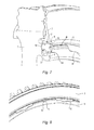
- the Figures 7 and 8 show a disc 1 equipped with a flange 3 held in place by a latch 7 associated with its locking screw 8.
- the disc 1 has on the flange 6 of the introduction windows 14 whose number and the angular sectors correspond to those of jaws 11 of the flange.
- two lug-shaped depressions 16 are hollowed out in the thickness of the disk 1, opposite a notch 15 made axially on this flange.
- These lunules preferably have, hollow, a shape similar to the convex shape of the outer face of the second portion 8b of the locking screw.
- the latch 7 and its locking screw 8 are provided to pass through the flange at its notch 13 and the flange 6 of the disk at its notch 15.
- the disk 1 in comparison with the discs of the prior art, has introduction windows 14 cut in the outer surface of the flange 6, two first notches 15 diametrically opposed and two lobes 16 located on the face of the disk facing the first two notches 15.
- the flange 3 according to the invention is modified in that it has jaw 11 regularly distributed on the circumference of its inner diameter. These claws are intended to position themselves behind the flange 6 of the disk 1, between the introduction windows 14 and serve as a fulcrum of the flange when it is pressed against the wall of the flange 6 which opens on the 5. As previously indicated, two second notches 13, without this number of two being imperative, are practiced in jaws 12 diametrically opposed.
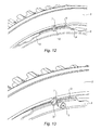
- the mounting of the flange on the disc begins with the introduction of two latches 7 in the groove 5 of the disk 1, preferably at an insertion window 14 close to one of the two lunulas 16. These lunulas correspond in effect to the final position that the locks will have at the end of assembly.
- the flange 3 is then also introduced into this groove 5, the claws 11 being positioned in front of the introduction windows 14 and the two jaws 12 having a notch 13 being in turn positioned opposite the two latches 7.
- the second step of the assembly consists in rotating the flange 3 and each latch 7 in the groove so that the latter and the second notches 13 are placed in front of the first notches 15 and lunules 16.
- the pressure against the flange applied to the flange 3 allows a good retention of the flange and prevents any rotation thereof, which eliminates the disadvantages encountered in the prior art.
- the recoil of the flange 3 relative to the face of the disk 1 during the tightening of the locking screw 8 does not have an adverse effect on the tightness of the blade cooling circuit or on the axial blocking of the blades because the flange is positioned in force, ie pressed against the disk with an elastic deformation.
- the seal is further maintained, even if the flange back, by a sealing tongue pressed into force in a groove of the disc.
Landscapes
- Engineering & Computer Science (AREA)
- Mechanical Engineering (AREA)
- General Engineering & Computer Science (AREA)
- Turbine Rotor Nozzle Sealing (AREA)
Claims (9)
- Mittel zur Druckbeaufschlagung eines Dichtflansches (3) des Kühlkreislaufs der Schaufeln einer Turbomaschine gegen eine Turbinenscheibe (1), die diese Schaufeln trägt, wobei die Scheibe auf ihrer nachgelagerten Seite einen ringförmigen Flansch (6) trägt, der radial orientiert ist, und mit dieser Seite eine Nut (5) abgrenzt, die geeignet ist, den Dichtflansch (3) aufzunehmen, wobei der Flansch mindestens zwei Ausschnitte auf seinem Rand aufweist, der der Unterseite der Nut (5) gegenüberliegend angeordnet ist, um Fenster (14) zum axialen Einführen in die Nut für Klauen (11) zu bilden, die von dem Umfang des Flansches (3) getragen sind, der zu der Nut (5) der Scheibe (1) zeigt, wobei das Mittel einen Riegel (7) aufweist, der geeignet ist, sich in der Nut (5) zwischen der Seite der Scheibe und dem Flansch zu positionieren,
dadurch gekennzeichnet, dass es außerdem ein Klemmmittel (8) aufweist, das gebildet ist, um sich gegen die Seite der Scheibe (1) abzustützen und mit dem Riegel zusammen zu wirken, um die Druckbeaufschlagung des Dichtflansches (3) gegen den Flansch (6) zu gewährleisten. - Mittel zur Druckbeaufschlagung nach Anspruch 1, wobei das Klemmmittel eine Schraube (8) ist und der Riegel eine Mutter (7) ist, die mindestens einen Flügel aufweist, der sich tangential in der Nut (5) erstreckt.
- Mittel zur Druckbeaufschlagung nach Anspruch 2, wobei die Klemmschraube (8) einen ersten Gewindeabschnitt (8a), der geeignet ist, mit einem Innengewinde (9) der Mutter zusammenwirken, und einen zweiten Abschnitt (8b) mit einem Durchmesser, der kleiner als jener des Innengewindes ist, aufweist, der geeignet ist, durch die Mutter durch zu gehen, um sich auf der Seite der Scheibe abzustützen und die Mutter (7) und den Dichtflansch (3) gegen den Flansch (6) zu drücken.
- Mittel zur Druckbeaufschlagung nach Anspruch 3, wobei die Außenseite des zweiten Abschnitts (8b) gewölbt ist, um mit einer Mulde (16) zusammenzuwirken, die in der Fläche der Scheibe ausgehöhlt ist.
- Turbinenscheibe für eine Turbomaschine, die auf ihrer nachgelagerten Seite einen ringförmigen Flansch (6) trägt, der radial orientiert ist, und mit dieser Seite eine Nut (5) abgrenzt, die geeignet ist, einen Dichtflansch (3) des Kühlkreislaufs der Schaufeln aufzunehmen, die von der Scheibe (1) getragen sind, dadurch gekennzeichnet, dass der Flansch (6) außerdem mindestens eine erste Öffnung (15) aufweist, die geeignet ist, dem Klemmmittel (8) den Durchgang eines Mittels zur Druckbeaufschlagung nach einem der Ansprüche 1 bis 4 zu ermöglichen.
- Ringförmiger Dichtflansch des Kühlkreislaufs der Schaufeln einer Turbomaschine, der Klauen (11) auf einem seiner Umfänge aufweist, dadurch gekennzeichnet, dass mindestens eine der Klauen (12) eine zweite Öffnung (13) aufweist, die geeignet ist, dem Klemmmittel (8) den Durchgang eines Mittels zur Druckbeaufschlagung nach einem der Ansprüche 1 bis 4 zu ermöglichen, um dem Klemmmittel zu erlauben, sich auf der nachgelagerten Seite der Scheibe (1) abzustützen, die die Schaufeln trägt.
- Turbinenscheibe nach Anspruch 5, die mit einem Dichtflansch (3) nach Anspruch 6 ausgestattet ist, der durch ein Mittel zur Druckbeaufschlagung nach einem der Ansprüche 1 bis 4 gegen einen ringförmigen Flansch (6) der Scheibe gehalten ist.
- Turbinenmodul einer Turbomaschine, umfassend eine Scheibe, die nach Anspruch 7 ausgestattet ist.
- Turbomaschine, umfassend ein Turbinenmodul nach dem vorhergehenden Anspruch.
Applications Claiming Priority (2)
| Application Number | Priority Date | Filing Date | Title |
|---|---|---|---|
| FR1050628A FR2955889B1 (fr) | 2010-01-29 | 2010-01-29 | Moyen de blocage d'un flasque d'etancheite sur un disque de turbine |
| PCT/FR2011/050183 WO2011092439A1 (fr) | 2010-01-29 | 2011-01-28 | Moyen de blocage d'un flasque d'étanchéité sur un disque de turbine |
Publications (2)
| Publication Number | Publication Date |
|---|---|
| EP2529083A1 EP2529083A1 (de) | 2012-12-05 |
| EP2529083B1 true EP2529083B1 (de) | 2015-07-29 |
Family
ID=42670364
Family Applications (1)
| Application Number | Title | Priority Date | Filing Date |
|---|---|---|---|
| EP11706889.0A Active EP2529083B1 (de) | 2010-01-29 | 2011-01-28 | Vorrichtung zur blockierung eines dichtungsrings auf einem turbinenrad |
Country Status (9)
| Country | Link |
|---|---|
| US (1) | US9033666B2 (de) |
| EP (1) | EP2529083B1 (de) |
| JP (1) | JP2013518212A (de) |
| CN (1) | CN102713161B (de) |
| BR (1) | BR112012017988A2 (de) |
| CA (1) | CA2788438A1 (de) |
| FR (1) | FR2955889B1 (de) |
| RU (1) | RU2563411C2 (de) |
| WO (1) | WO2011092439A1 (de) |
Families Citing this family (26)
| Publication number | Priority date | Publication date | Assignee | Title |
|---|---|---|---|---|
| US10544677B2 (en) * | 2017-09-01 | 2020-01-28 | United Technologies Corporation | Turbine disk |
| US8840375B2 (en) * | 2011-03-21 | 2014-09-23 | United Technologies Corporation | Component lock for a gas turbine engine |
| FR2981132B1 (fr) * | 2011-10-10 | 2013-12-06 | Snecma | Ensemble pour turbomachine a refroidissement de disque |
| US9249676B2 (en) | 2012-06-05 | 2016-02-02 | United Technologies Corporation | Turbine rotor cover plate lock |
| US9228443B2 (en) * | 2012-10-31 | 2016-01-05 | Solar Turbines Incorporated | Turbine rotor assembly |
| WO2015026591A1 (en) * | 2013-08-19 | 2015-02-26 | United Technologies Corporation | Gas turbine engine duct assembly |
| EP2933436A1 (de) * | 2014-04-15 | 2015-10-21 | Siemens Aktiengesellschaft | Radscheibe mit wenigstens einem Dichtblech |
| FR3026430B1 (fr) * | 2014-09-29 | 2020-07-10 | Safran Aircraft Engines | Roue de turbine dans une turbomachine |
| KR102182102B1 (ko) * | 2014-11-27 | 2020-11-23 | 한화에어로스페이스 주식회사 | 터빈 장치 |
| US9732619B2 (en) | 2015-03-31 | 2017-08-15 | United Technologies Corporation | Retaining rings for turbomachine disk and coverplate assemblies |
| US10047865B2 (en) * | 2015-12-07 | 2018-08-14 | General Electric Company | Steam turbine rotor seal radial key member, related assembly and steam turbine |
| US10683756B2 (en) | 2016-02-03 | 2020-06-16 | Dresser-Rand Company | System and method for cooling a fluidized catalytic cracking expander |
| US10823012B2 (en) * | 2016-05-20 | 2020-11-03 | Raytheon Technologies Corporation | Fastener openings for stress distribution |
| US10472968B2 (en) | 2017-09-01 | 2019-11-12 | United Technologies Corporation | Turbine disk |
| US10641110B2 (en) | 2017-09-01 | 2020-05-05 | United Technologies Corporation | Turbine disk |
| US10724374B2 (en) | 2017-09-01 | 2020-07-28 | Raytheon Technologies Corporation | Turbine disk |
| US10550702B2 (en) | 2017-09-01 | 2020-02-04 | United Technologies Corporation | Turbine disk |
| US10669875B2 (en) | 2018-03-28 | 2020-06-02 | Solar Turbines Incorporated | Cross key anti-rotation spacer |
| CN108798789B (zh) * | 2018-06-07 | 2020-12-08 | 中国航发湖南动力机械研究所 | 锁片止动机构及涡轮盘组件 |
| FR3091719B1 (fr) * | 2019-01-15 | 2021-02-12 | Safran Aircraft Engines | secteur de flasque d’etancheite de disque de rotor |
| CN112160798A (zh) * | 2020-09-18 | 2021-01-01 | 中国航发四川燃气涡轮研究院 | 航空发动机涡轮挡板定位结构及其航空发动机 |
| CN114278385A (zh) * | 2021-12-16 | 2022-04-05 | 北京航空航天大学 | 一种带有遮热板和空气夹层的新型涡轮盘腔隔热结构 |
| CN115405369B (zh) * | 2022-08-30 | 2025-11-04 | 中国航发沈阳发动机研究所 | 一种航空发动机涡轮盘与转子叶片连接结构及其装配方法 |
| KR102838243B1 (ko) * | 2023-02-16 | 2025-07-23 | 두산에너빌리티 주식회사 | 터빈 블레이드의 씰 조립구조와 이를 포함하는 가스 터빈 |
| KR102838241B1 (ko) * | 2023-04-04 | 2025-07-23 | 두산에너빌리티 주식회사 | 터빈 블레이드의 씰 조립구조와 이를 포함하는 가스 터빈 |
| KR102887774B1 (ko) * | 2023-04-04 | 2025-11-17 | 두산에너빌리티 주식회사 | 터빈 블레이드의 씰 조립구조와 이를 포함하는 가스 터빈 |
Family Cites Families (21)
| Publication number | Priority date | Publication date | Assignee | Title |
|---|---|---|---|---|
| BE551145A (de) * | 1955-09-26 | |||
| US3572966A (en) * | 1969-01-17 | 1971-03-30 | Westinghouse Electric Corp | Seal plates for root cooled turbine rotor blades |
| US4021138A (en) * | 1975-11-03 | 1977-05-03 | Westinghouse Electric Corporation | Rotor disk, blade, and seal plate assembly for cooled turbine rotor blades |
| US4344740A (en) * | 1979-09-28 | 1982-08-17 | United Technologies Corporation | Rotor assembly |
| US4803893A (en) * | 1987-09-24 | 1989-02-14 | United Technologies Corporation | High speed rotor balance system |
| GB2244100A (en) * | 1990-05-16 | 1991-11-20 | Rolls Royce Plc | Retaining gas turbine rotor blades |
| RU2018037C1 (ru) * | 1990-10-17 | 1994-08-15 | Виталий Сергеевич Максимов | Рабочее колесо турбомашины |
| US5275534A (en) * | 1991-10-30 | 1994-01-04 | General Electric Company | Turbine disk forward seal assembly |
| US5277548A (en) * | 1991-12-31 | 1994-01-11 | United Technologies Corporation | Non-integral rotor blade platform |
| US5211407A (en) * | 1992-04-30 | 1993-05-18 | General Electric Company | Compressor rotor cross shank leak seal for axial dovetails |
| JPH0783003A (ja) * | 1993-09-14 | 1995-03-28 | Ishikawajima Harima Heavy Ind Co Ltd | タービンのローター |
| GB9517369D0 (en) * | 1995-08-24 | 1995-10-25 | Rolls Royce Plc | Bladed rotor |
| CA2321375C (en) * | 1999-09-30 | 2005-11-22 | Mitsubishi Heavy Industries, Ltd. | An arrangement for sealing a steam-cooled gas turbine |
| GB9925261D0 (en) | 1999-10-27 | 1999-12-29 | Rolls Royce Plc | Locking devices |
| FR2850130B1 (fr) * | 2003-01-16 | 2006-01-20 | Snecma Moteurs | Dispositif pour retenir un flasque annulaire contre une face radiale d'un disque |
| GB2405183A (en) * | 2003-08-21 | 2005-02-23 | Rolls Royce Plc | Ring and channel arrangement for joining components |
| FR2868808B1 (fr) | 2004-04-09 | 2008-08-29 | Snecma Moteurs Sa | Dispositif de retenue axiale d'aubes sur un disque de rotor d'une turbomachine |
| GB0413652D0 (en) * | 2004-06-18 | 2004-07-21 | Rolls Royce Plc | Gas turbine engine structure |
| GB0423363D0 (en) * | 2004-10-21 | 2004-11-24 | Rolls Royce Plc | Rotor assembly retaining apparatus |
| JP2007247406A (ja) * | 2006-03-13 | 2007-09-27 | Ihi Corp | ファンブレードの保持構造 |
| EP2011969A1 (de) * | 2007-07-03 | 2009-01-07 | Siemens Aktiengesellschaft | Turbinenanordnung sowie Verfahren zur Befestigung eines Einbauelements |
-
2010
- 2010-01-29 FR FR1050628A patent/FR2955889B1/fr not_active Expired - Fee Related
-
2011
- 2011-01-28 JP JP2012550501A patent/JP2013518212A/ja not_active Ceased
- 2011-01-28 CN CN201180005982.8A patent/CN102713161B/zh active Active
- 2011-01-28 EP EP11706889.0A patent/EP2529083B1/de active Active
- 2011-01-28 CA CA2788438A patent/CA2788438A1/fr not_active Abandoned
- 2011-01-28 RU RU2012136822/06A patent/RU2563411C2/ru active
- 2011-01-28 BR BR112012017988A patent/BR112012017988A2/pt not_active IP Right Cessation
- 2011-01-28 WO PCT/FR2011/050183 patent/WO2011092439A1/fr not_active Ceased
- 2011-01-28 US US13/575,234 patent/US9033666B2/en active Active
Also Published As
| Publication number | Publication date |
|---|---|
| BR112012017988A2 (pt) | 2016-05-03 |
| CN102713161A (zh) | 2012-10-03 |
| RU2563411C2 (ru) | 2015-09-20 |
| FR2955889B1 (fr) | 2012-11-16 |
| RU2012136822A (ru) | 2014-03-10 |
| CN102713161B (zh) | 2015-08-19 |
| WO2011092439A1 (fr) | 2011-08-04 |
| US9033666B2 (en) | 2015-05-19 |
| EP2529083A1 (de) | 2012-12-05 |
| CA2788438A1 (fr) | 2011-08-04 |
| US20120315142A1 (en) | 2012-12-13 |
| FR2955889A1 (fr) | 2011-08-05 |
| JP2013518212A (ja) | 2013-05-20 |
Similar Documents
| Publication | Publication Date | Title |
|---|---|---|
| EP2529083B1 (de) | Vorrichtung zur blockierung eines dichtungsrings auf einem turbinenrad | |
| EP1584794B1 (de) | Turbomaschinenrotorscheibe mit einer Axialhalterung für die Laufschaufeln | |
| EP1498579B1 (de) | Rotorscheibe mit einem ringförmigen Flansch | |
| FR2852053A1 (fr) | Turbine haute pression pour turbomachine | |
| FR2931197A1 (fr) | Organe de verrouillage de secteurs d'anneau sur un carter de turbomachine, comprenant des passages axiaux pour sa prehension | |
| EP1845235B1 (de) | Axiale Haltevorrichtung für eine Schaufeldeckplatte einer Turbinenscheibe | |
| FR2935777A1 (fr) | Chambre de combustion de turbomachine | |
| WO2011069940A1 (fr) | Ensemble d'un jonc de retenue et d'un flasque de maintien dudit jonc | |
| CA2919596A1 (fr) | Couvercle de compresseur centrifuge de turbomachine apte a etre fixe par l'aval pres de son bord amont, turbomachine comportant ce couvercle | |
| EP3584413A1 (de) | Ringförmiges und aufgeschrumpftes gussteil für ein turbotriebwerk eines luftfahrzeugs | |
| FR2914349A1 (fr) | Interface distributeur couronne a aubes/support pour turbine a vapeur | |
| EP3033495B1 (de) | Verbesserung an der verriegelung von klingentragekomponenten | |
| EP1985834B1 (de) | Klappenventil für ein Kühlungssystem in einem Strahltriebwerk | |
| EP0526373B1 (de) | Verriegelbare Rohrverbindung mit Abdichtanordnung aus einem Verbundwerkstoff | |
| WO1997042432A1 (fr) | Appareil d'accouplement hydrocinetique a piece d'entrainement de languettes, notamment pour vehicule automobile | |
| EP1517004B1 (de) | Schaufelrad für eine Turbomaschine und Methode zur Montage der Schaufeln auf der Nabe | |
| FR2958322A1 (fr) | Rotor de moteur a turbine a gaz comprenant un tambour de rotor et une couronne de rotor | |
| EP1617046B1 (de) | Wellen- und Lageranordnung | |
| FR3082228A1 (fr) | Piece de turbomachine comprenant une rondelle cooperant avec un lamage | |
| EP1580402B1 (de) | Turbomaschine mit zwei unter axialer Spannung stehenden Unterteilen | |
| WO2024052238A1 (fr) | Obturateur en ligne de grand diametre comportant une plaque d'obturation | |
| FR3051220A1 (fr) | Obturateur d'un orifice d'endoscopie d'une turbine de turbomachine | |
| EP2013501B1 (de) | Kupplungslager | |
| FR3121168A1 (fr) | Réduction des fuites dans une turbomachine | |
| FR3116305A1 (fr) | Arbre de liaison d’un corps haute pression d’une turbomachine |
Legal Events
| Date | Code | Title | Description |
|---|---|---|---|
| PUAI | Public reference made under article 153(3) epc to a published international application that has entered the european phase |
Free format text: ORIGINAL CODE: 0009012 |
|
| 17P | Request for examination filed |
Effective date: 20120823 |
|
| AK | Designated contracting states |
Kind code of ref document: A1 Designated state(s): AL AT BE BG CH CY CZ DE DK EE ES FI FR GB GR HR HU IE IS IT LI LT LU LV MC MK MT NL NO PL PT RO RS SE SI SK SM TR |
|
| DAX | Request for extension of the european patent (deleted) | ||
| GRAP | Despatch of communication of intention to grant a patent |
Free format text: ORIGINAL CODE: EPIDOSNIGR1 |
|
| INTG | Intention to grant announced |
Effective date: 20150212 |
|
| GRAS | Grant fee paid |
Free format text: ORIGINAL CODE: EPIDOSNIGR3 |
|
| GRAA | (expected) grant |
Free format text: ORIGINAL CODE: 0009210 |
|
| AK | Designated contracting states |
Kind code of ref document: B1 Designated state(s): AL AT BE BG CH CY CZ DE DK EE ES FI FR GB GR HR HU IE IS IT LI LT LU LV MC MK MT NL NO PL PT RO RS SE SI SK SM TR |
|
| REG | Reference to a national code |
Ref country code: GB Ref legal event code: FG4D Free format text: NOT ENGLISH |
|
| REG | Reference to a national code |
Ref country code: CH Ref legal event code: EP |
|
| REG | Reference to a national code |
Ref country code: AT Ref legal event code: REF Ref document number: 739474 Country of ref document: AT Kind code of ref document: T Effective date: 20150815 |
|
| REG | Reference to a national code |
Ref country code: IE Ref legal event code: FG4D Free format text: LANGUAGE OF EP DOCUMENT: FRENCH |
|
| REG | Reference to a national code |
Ref country code: DE Ref legal event code: R096 Ref document number: 602011018208 Country of ref document: DE |
|
| RAP2 | Party data changed (patent owner data changed or rights of a patent transferred) |
Owner name: SNECMA |
|
| REG | Reference to a national code |
Ref country code: SE Ref legal event code: TRGR |
|
| REG | Reference to a national code |
Ref country code: AT Ref legal event code: MK05 Ref document number: 739474 Country of ref document: AT Kind code of ref document: T Effective date: 20150729 |
|
| REG | Reference to a national code |
Ref country code: LT Ref legal event code: MG4D |
|
| REG | Reference to a national code |
Ref country code: NL Ref legal event code: MP Effective date: 20150729 |
|
| REG | Reference to a national code |
Ref country code: FR Ref legal event code: PLFP Year of fee payment: 6 |
|
| PG25 | Lapsed in a contracting state [announced via postgrant information from national office to epo] |
Ref country code: NO Free format text: LAPSE BECAUSE OF FAILURE TO SUBMIT A TRANSLATION OF THE DESCRIPTION OR TO PAY THE FEE WITHIN THE PRESCRIBED TIME-LIMIT Effective date: 20151029 Ref country code: LT Free format text: LAPSE BECAUSE OF FAILURE TO SUBMIT A TRANSLATION OF THE DESCRIPTION OR TO PAY THE FEE WITHIN THE PRESCRIBED TIME-LIMIT Effective date: 20150729 Ref country code: LV Free format text: LAPSE BECAUSE OF FAILURE TO SUBMIT A TRANSLATION OF THE DESCRIPTION OR TO PAY THE FEE WITHIN THE PRESCRIBED TIME-LIMIT Effective date: 20150729 Ref country code: GR Free format text: LAPSE BECAUSE OF FAILURE TO SUBMIT A TRANSLATION OF THE DESCRIPTION OR TO PAY THE FEE WITHIN THE PRESCRIBED TIME-LIMIT Effective date: 20151030 Ref country code: FI Free format text: LAPSE BECAUSE OF FAILURE TO SUBMIT A TRANSLATION OF THE DESCRIPTION OR TO PAY THE FEE WITHIN THE PRESCRIBED TIME-LIMIT Effective date: 20150729 |
|
| PG25 | Lapsed in a contracting state [announced via postgrant information from national office to epo] |
Ref country code: IS Free format text: LAPSE BECAUSE OF FAILURE TO SUBMIT A TRANSLATION OF THE DESCRIPTION OR TO PAY THE FEE WITHIN THE PRESCRIBED TIME-LIMIT Effective date: 20151129 Ref country code: HR Free format text: LAPSE BECAUSE OF FAILURE TO SUBMIT A TRANSLATION OF THE DESCRIPTION OR TO PAY THE FEE WITHIN THE PRESCRIBED TIME-LIMIT Effective date: 20150729 Ref country code: PT Free format text: LAPSE BECAUSE OF FAILURE TO SUBMIT A TRANSLATION OF THE DESCRIPTION OR TO PAY THE FEE WITHIN THE PRESCRIBED TIME-LIMIT Effective date: 20151130 Ref country code: AT Free format text: LAPSE BECAUSE OF FAILURE TO SUBMIT A TRANSLATION OF THE DESCRIPTION OR TO PAY THE FEE WITHIN THE PRESCRIBED TIME-LIMIT Effective date: 20150729 Ref country code: RS Free format text: LAPSE BECAUSE OF FAILURE TO SUBMIT A TRANSLATION OF THE DESCRIPTION OR TO PAY THE FEE WITHIN THE PRESCRIBED TIME-LIMIT Effective date: 20150729 Ref country code: PL Free format text: LAPSE BECAUSE OF FAILURE TO SUBMIT A TRANSLATION OF THE DESCRIPTION OR TO PAY THE FEE WITHIN THE PRESCRIBED TIME-LIMIT Effective date: 20150729 Ref country code: ES Free format text: LAPSE BECAUSE OF FAILURE TO SUBMIT A TRANSLATION OF THE DESCRIPTION OR TO PAY THE FEE WITHIN THE PRESCRIBED TIME-LIMIT Effective date: 20150729 |
|
| PG25 | Lapsed in a contracting state [announced via postgrant information from national office to epo] |
Ref country code: NL Free format text: LAPSE BECAUSE OF FAILURE TO SUBMIT A TRANSLATION OF THE DESCRIPTION OR TO PAY THE FEE WITHIN THE PRESCRIBED TIME-LIMIT Effective date: 20150729 |
|
| PG25 | Lapsed in a contracting state [announced via postgrant information from national office to epo] |
Ref country code: DK Free format text: LAPSE BECAUSE OF FAILURE TO SUBMIT A TRANSLATION OF THE DESCRIPTION OR TO PAY THE FEE WITHIN THE PRESCRIBED TIME-LIMIT Effective date: 20150729 Ref country code: EE Free format text: LAPSE BECAUSE OF FAILURE TO SUBMIT A TRANSLATION OF THE DESCRIPTION OR TO PAY THE FEE WITHIN THE PRESCRIBED TIME-LIMIT Effective date: 20150729 Ref country code: CZ Free format text: LAPSE BECAUSE OF FAILURE TO SUBMIT A TRANSLATION OF THE DESCRIPTION OR TO PAY THE FEE WITHIN THE PRESCRIBED TIME-LIMIT Effective date: 20150729 Ref country code: SK Free format text: LAPSE BECAUSE OF FAILURE TO SUBMIT A TRANSLATION OF THE DESCRIPTION OR TO PAY THE FEE WITHIN THE PRESCRIBED TIME-LIMIT Effective date: 20150729 |
|
| REG | Reference to a national code |
Ref country code: DE Ref legal event code: R097 Ref document number: 602011018208 Country of ref document: DE |
|
| PG25 | Lapsed in a contracting state [announced via postgrant information from national office to epo] |
Ref country code: BE Free format text: LAPSE BECAUSE OF NON-PAYMENT OF DUE FEES Effective date: 20160131 Ref country code: RO Free format text: LAPSE BECAUSE OF FAILURE TO SUBMIT A TRANSLATION OF THE DESCRIPTION OR TO PAY THE FEE WITHIN THE PRESCRIBED TIME-LIMIT Effective date: 20150729 |
|
| PLBE | No opposition filed within time limit |
Free format text: ORIGINAL CODE: 0009261 |
|
| STAA | Information on the status of an ep patent application or granted ep patent |
Free format text: STATUS: NO OPPOSITION FILED WITHIN TIME LIMIT |
|
| 26N | No opposition filed |
Effective date: 20160502 |
|
| PG25 | Lapsed in a contracting state [announced via postgrant information from national office to epo] |
Ref country code: LU Free format text: LAPSE BECAUSE OF FAILURE TO SUBMIT A TRANSLATION OF THE DESCRIPTION OR TO PAY THE FEE WITHIN THE PRESCRIBED TIME-LIMIT Effective date: 20160128 Ref country code: SI Free format text: LAPSE BECAUSE OF FAILURE TO SUBMIT A TRANSLATION OF THE DESCRIPTION OR TO PAY THE FEE WITHIN THE PRESCRIBED TIME-LIMIT Effective date: 20150729 |
|
| REG | Reference to a national code |
Ref country code: CH Ref legal event code: PL |
|
| PG25 | Lapsed in a contracting state [announced via postgrant information from national office to epo] |
Ref country code: MC Free format text: LAPSE BECAUSE OF FAILURE TO SUBMIT A TRANSLATION OF THE DESCRIPTION OR TO PAY THE FEE WITHIN THE PRESCRIBED TIME-LIMIT Effective date: 20150729 |
|
| PG25 | Lapsed in a contracting state [announced via postgrant information from national office to epo] |
Ref country code: CH Free format text: LAPSE BECAUSE OF NON-PAYMENT OF DUE FEES Effective date: 20160131 Ref country code: LI Free format text: LAPSE BECAUSE OF NON-PAYMENT OF DUE FEES Effective date: 20160131 |
|
| REG | Reference to a national code |
Ref country code: IE Ref legal event code: MM4A |
|
| REG | Reference to a national code |
Ref country code: FR Ref legal event code: PLFP Year of fee payment: 7 |
|
| PG25 | Lapsed in a contracting state [announced via postgrant information from national office to epo] |
Ref country code: IE Free format text: LAPSE BECAUSE OF NON-PAYMENT OF DUE FEES Effective date: 20160128 |
|
| PG25 | Lapsed in a contracting state [announced via postgrant information from national office to epo] |
Ref country code: MT Free format text: LAPSE BECAUSE OF FAILURE TO SUBMIT A TRANSLATION OF THE DESCRIPTION OR TO PAY THE FEE WITHIN THE PRESCRIBED TIME-LIMIT Effective date: 20150729 |
|
| REG | Reference to a national code |
Ref country code: FR Ref legal event code: PLFP Year of fee payment: 8 |
|
| PG25 | Lapsed in a contracting state [announced via postgrant information from national office to epo] |
Ref country code: CY Free format text: LAPSE BECAUSE OF FAILURE TO SUBMIT A TRANSLATION OF THE DESCRIPTION OR TO PAY THE FEE WITHIN THE PRESCRIBED TIME-LIMIT Effective date: 20150729 Ref country code: HU Free format text: LAPSE BECAUSE OF FAILURE TO SUBMIT A TRANSLATION OF THE DESCRIPTION OR TO PAY THE FEE WITHIN THE PRESCRIBED TIME-LIMIT; INVALID AB INITIO Effective date: 20110128 Ref country code: SM Free format text: LAPSE BECAUSE OF FAILURE TO SUBMIT A TRANSLATION OF THE DESCRIPTION OR TO PAY THE FEE WITHIN THE PRESCRIBED TIME-LIMIT Effective date: 20150729 |
|
| PG25 | Lapsed in a contracting state [announced via postgrant information from national office to epo] |
Ref country code: TR Free format text: LAPSE BECAUSE OF FAILURE TO SUBMIT A TRANSLATION OF THE DESCRIPTION OR TO PAY THE FEE WITHIN THE PRESCRIBED TIME-LIMIT Effective date: 20150729 Ref country code: MK Free format text: LAPSE BECAUSE OF FAILURE TO SUBMIT A TRANSLATION OF THE DESCRIPTION OR TO PAY THE FEE WITHIN THE PRESCRIBED TIME-LIMIT Effective date: 20150729 |
|
| PG25 | Lapsed in a contracting state [announced via postgrant information from national office to epo] |
Ref country code: BG Free format text: LAPSE BECAUSE OF FAILURE TO SUBMIT A TRANSLATION OF THE DESCRIPTION OR TO PAY THE FEE WITHIN THE PRESCRIBED TIME-LIMIT Effective date: 20150729 |
|
| PG25 | Lapsed in a contracting state [announced via postgrant information from national office to epo] |
Ref country code: AL Free format text: LAPSE BECAUSE OF FAILURE TO SUBMIT A TRANSLATION OF THE DESCRIPTION OR TO PAY THE FEE WITHIN THE PRESCRIBED TIME-LIMIT Effective date: 20150729 |
|
| PGFP | Annual fee paid to national office [announced via postgrant information from national office to epo] |
Ref country code: SE Payment date: 20260121 Year of fee payment: 16 |
|
| PGFP | Annual fee paid to national office [announced via postgrant information from national office to epo] |
Ref country code: GB Payment date: 20260122 Year of fee payment: 16 |
|
| PGFP | Annual fee paid to national office [announced via postgrant information from national office to epo] |
Ref country code: DE Payment date: 20260120 Year of fee payment: 16 |
|
| PGFP | Annual fee paid to national office [announced via postgrant information from national office to epo] |
Ref country code: IT Payment date: 20260130 Year of fee payment: 16 |
|
| PGFP | Annual fee paid to national office [announced via postgrant information from national office to epo] |
Ref country code: FR Payment date: 20260121 Year of fee payment: 16 |