EP2530201B1 - Structure de croisement de tramway à pointe mobile - Google Patents
Structure de croisement de tramway à pointe mobile Download PDFInfo
- Publication number
- EP2530201B1 EP2530201B1 EP10843781.5A EP10843781A EP2530201B1 EP 2530201 B1 EP2530201 B1 EP 2530201B1 EP 10843781 A EP10843781 A EP 10843781A EP 2530201 B1 EP2530201 B1 EP 2530201B1
- Authority
- EP
- European Patent Office
- Prior art keywords
- movable point
- movable
- turnout
- rails
- support cradle
- Prior art date
- Legal status (The legal status is an assumption and is not a legal conclusion. Google has not performed a legal analysis and makes no representation as to the accuracy of the status listed.)
- Not-in-force
Links
- 238000005096 rolling process Methods 0.000 claims description 9
- 238000005192 partition Methods 0.000 claims description 2
- 230000001681 protective effect Effects 0.000 claims description 2
- 230000000295 complement effect Effects 0.000 claims 1
- 238000006073 displacement reaction Methods 0.000 description 5
- 238000005452 bending Methods 0.000 description 3
- 238000000926 separation method Methods 0.000 description 2
- 229910000617 Mangalloy Inorganic materials 0.000 description 1
- 229910000831 Steel Inorganic materials 0.000 description 1
- 230000000712 assembly Effects 0.000 description 1
- 238000000429 assembly Methods 0.000 description 1
- 238000005266 casting Methods 0.000 description 1
- 230000006866 deterioration Effects 0.000 description 1
- 230000008030 elimination Effects 0.000 description 1
- 238000003379 elimination reaction Methods 0.000 description 1
- 238000003780 insertion Methods 0.000 description 1
- 230000037431 insertion Effects 0.000 description 1
- 239000000463 material Substances 0.000 description 1
- 238000000034 method Methods 0.000 description 1
- 230000000630 rising effect Effects 0.000 description 1
- 230000035939 shock Effects 0.000 description 1
- 239000010959 steel Substances 0.000 description 1
Images





Classifications
-
- E—FIXED CONSTRUCTIONS
- E01—CONSTRUCTION OF ROADS, RAILWAYS, OR BRIDGES
- E01B—PERMANENT WAY; PERMANENT-WAY TOOLS; MACHINES FOR MAKING RAILWAYS OF ALL KINDS
- E01B7/00—Switches; Crossings
- E01B7/10—Frogs
- E01B7/14—Frogs with movable parts
-
- H—ELECTRICITY
- H01—ELECTRIC ELEMENTS
- H01M—PROCESSES OR MEANS, e.g. BATTERIES, FOR THE DIRECT CONVERSION OF CHEMICAL ENERGY INTO ELECTRICAL ENERGY
- H01M8/00—Fuel cells; Manufacture thereof
- H01M8/10—Fuel cells with solid electrolytes
- H01M8/12—Fuel cells with solid electrolytes operating at high temperature, e.g. with stabilised ZrO2 electrolyte
- H01M8/1213—Fuel cells with solid electrolytes operating at high temperature, e.g. with stabilised ZrO2 electrolyte characterised by the electrode/electrolyte combination or the supporting material
-
- H—ELECTRICITY
- H01—ELECTRIC ELEMENTS
- H01M—PROCESSES OR MEANS, e.g. BATTERIES, FOR THE DIRECT CONVERSION OF CHEMICAL ENERGY INTO ELECTRICAL ENERGY
- H01M8/00—Fuel cells; Manufacture thereof
- H01M8/10—Fuel cells with solid electrolytes
- H01M8/12—Fuel cells with solid electrolytes operating at high temperature, e.g. with stabilised ZrO2 electrolyte
- H01M8/1286—Fuel cells applied on a support, e.g. miniature fuel cells deposited on silica supports
-
- H—ELECTRICITY
- H01—ELECTRIC ELEMENTS
- H01M—PROCESSES OR MEANS, e.g. BATTERIES, FOR THE DIRECT CONVERSION OF CHEMICAL ENERGY INTO ELECTRICAL ENERGY
- H01M8/00—Fuel cells; Manufacture thereof
- H01M8/24—Grouping of fuel cells, e.g. stacking of fuel cells
- H01M8/241—Grouping of fuel cells, e.g. stacking of fuel cells with solid or matrix-supported electrolytes
- H01M8/2425—High-temperature cells with solid electrolytes
- H01M8/243—Grouping of unit cells of tubular or cylindrical configuration
-
- H—ELECTRICITY
- H01—ELECTRIC ELEMENTS
- H01M—PROCESSES OR MEANS, e.g. BATTERIES, FOR THE DIRECT CONVERSION OF CHEMICAL ENERGY INTO ELECTRICAL ENERGY
- H01M8/00—Fuel cells; Manufacture thereof
- H01M8/24—Grouping of fuel cells, e.g. stacking of fuel cells
- H01M8/2465—Details of groupings of fuel cells
- H01M8/2484—Details of groupings of fuel cells characterised by external manifolds
- H01M8/2485—Arrangements for sealing external manifolds; Arrangements for mounting external manifolds around a stack
-
- H—ELECTRICITY
- H01—ELECTRIC ELEMENTS
- H01M—PROCESSES OR MEANS, e.g. BATTERIES, FOR THE DIRECT CONVERSION OF CHEMICAL ENERGY INTO ELECTRICAL ENERGY
- H01M8/00—Fuel cells; Manufacture thereof
- H01M8/10—Fuel cells with solid electrolytes
- H01M8/12—Fuel cells with solid electrolytes operating at high temperature, e.g. with stabilised ZrO2 electrolyte
- H01M2008/1293—Fuel cells with solid oxide electrolytes
-
- Y—GENERAL TAGGING OF NEW TECHNOLOGICAL DEVELOPMENTS; GENERAL TAGGING OF CROSS-SECTIONAL TECHNOLOGIES SPANNING OVER SEVERAL SECTIONS OF THE IPC; TECHNICAL SUBJECTS COVERED BY FORMER USPC CROSS-REFERENCE ART COLLECTIONS [XRACs] AND DIGESTS
- Y02—TECHNOLOGIES OR APPLICATIONS FOR MITIGATION OR ADAPTATION AGAINST CLIMATE CHANGE
- Y02E—REDUCTION OF GREENHOUSE GAS [GHG] EMISSIONS, RELATED TO ENERGY GENERATION, TRANSMISSION OR DISTRIBUTION
- Y02E60/00—Enabling technologies; Technologies with a potential or indirect contribution to GHG emissions mitigation
- Y02E60/30—Hydrogen technology
- Y02E60/50—Fuel cells
Definitions
- the present invention relates to a tram movable point turnout structure that improves the currently existing turnouts, facilitating the handling, as well as the replacement operations of worn parts and making it possible to completely eliminate the handling noise and also the bending stresses to which the movable points of the conventional turnouts are subjected.
- the turnout is a track apparatus that allows the separation of a rail track into two or more tracks, the axes which tangentially contact with that of the first one or at a very small angle with it.
- the simplest case of a turnout is the one called simple, or with two tracks that gives way to the circulation that take it to one track or the other.
- the main one receives the name of direct track and the other the diverging track.
- the separation and the turnout of the rolling of both tracks is produced by using the following elements: the turnout and the turnout, which along with the joining rails between them, form the three main parts of the apparatus these being the turnout, the joining or intermediate rails and the turnout itself.
- the turnout is the element of the turnout where there is the superposition of the travelled roads.
- the most common one consists of common turnout, check rails and rails.
- the turnout of common turnouts is the joining of two rails that intersect with each other.
- a discontinuity is introduced in both rails, which empty space is called a gap.
- the extension that the rails have to allow the holding of the wheel rolling on the exterior end of the rim when the flange goes through the gap is called wing rails.
- the guard rails are intended to ensure the rail axis guiding when one of its wheels crosses the gap, avoiding the derailment of the vehicle and the deterioration of the common turnout. During the transit of the axles of the vehicles through the turnout, the collision of the wheels on common turnout areas may occur.
- shocks have two important consequences:
- Moving elements are inserted to suppress the gap removing it, keeping the corresponding common crossing wing rail. In this way, the check rails are unnecessary.
- the flexible movable point turnout with common turnout is a procedure to remove the gap in this type of common turnouts by bending the point of the common turnout, attaching one of its sides to the corresponding wing rail. In this way the gap disappears.
- the central block of the flexible movable common turnout consists of a forged, single piece, manufactured from standardised steel (as shown, for instance, in ES 2 265 237 A1 ).
- This mechanism has the following drawbacks:
- the turnout with movable wing rails makes it possible to totally remove the gap totally removing the gap keeping the point of the common turnout fastened and moving the corresponding wing rail.
- the invention proposes to a movable tram turnout structure that has a characteristic structure that facilitates the handling and also the operations of replacement of worn parts, making it possible to totally eliminate the handling noise.
- the turnout structure is characterised in that it comprises a support cradle located in a gap corresponding to an empty space which interrupts the continuity of two rails turnout from two different tracks, so that said support cradle comprises a central space where a movable point is attached by using a transverse guidance system allowing said movable point to be moved without bending stress on the same.
- a support cradle located in a gap corresponding to an empty space which interrupts the continuity of two rails turnout from two different tracks, so that said support cradle comprises a central space where a movable point is attached by using a transverse guidance system allowing said movable point to be moved without bending stress on the same.
- the support cradle has two pairs of end rail sections that are a continuation of two interrupted rails that cross from the two different tracks so that such end rail sections of the support cradle are interrupted in a central area (central space) where the movable point with transverse displacement is located.
- the movable point has two side rolling rail portions that converge towards the narrowest end of said movable point, so that depending on the end position on said movable point, the wheel of the railway or tramway will rest on one or the other side rolling portion that will be a continuation of the respective pair of end rail sections of the support cradle.
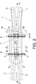
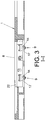
- the tram movable point turnout structure is defined by a support cradle 1 fastened in correspondence with the turnout interruption 2 of two rails 3 and 4 belonging to two different tracks 5 and 6, said cradle having a central space 7 housing a movable point 8 independent and linked to the support cradle 1 by means of a pair of transversal guides 9.
- the movable point 8 can take two end positions with transverse displacement corresponding to one of the two rails 3 or 4 that intersect depending on the selected track 5 or 6.
- the support cradle 1 has two pairs of end rail sections 10 and 11 that are a continuation of the two interrupted rails 3 and 4 which intersect from the two different tracks 5 and 6, so that such end rail sections 10-11 of the support cradle 1 are interrupted in a central area (central space 7) where the movable point 8 with transverse displacement is located.
- the movable point 8 has two side rail rolling portions 12 that converge towards the narrowest end of said movable point 8 such that depending on the end position of said movable point 8, the railway or tramway wheel 13 will rest on one or another side rolling portion 13 which will be a continuation of the respective pair of end rail sections 10 or 11 of the support cradle 1.
- Each transversal guide 9 comprises a guide-rail 14 immobilised by means of screws 15 and nuts 16, on which a car 17 is attached by means of a guidance system that includes rollers 18, elastic scrapers 19 and protective caps 20, attaching the movable point 8 to said cars.
- the narrowest part of the movable point 8 has on its upper surface of a smooth end ramp 22 descending outwards that facilitates the rolling of the respective wheel 13 of the railway or tramway when contacting with that specific part.
- the widest end of the movable point 8 has a characteristic recess 23 including two planes 24 complemented with two other planes 25 of the support cradle 1 where the movable point 8 stops in its usage end positions.
- the movable point 8 has two side recesses 26 encasing the cars 17 of the transversal guides 9.
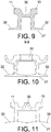
- the support cradle 1 has a characteristic robust structure comprising a horizontal base 27 from the central part from which surrounding side walls 28 with opposite end bracings delimiting the central space 7 where the movable point 8 and also the two transversal guides 9 are housed, extend upward.
- Said surrounding side walls 28 extend by their ends in partitions 29 finished at the top by centred bridges 30 and the pairs of end rail sections 10-11.
- the support cradle 1 includes a center rib 31 which includes the planes 25 where the planes 24 of the movable point stop when it is located in one of its stable, end positions, also including longitudinal wings 32 which are an extension of the sides of the horizontal base 27.
Landscapes
- Engineering & Computer Science (AREA)
- General Chemical & Material Sciences (AREA)
- Manufacturing & Machinery (AREA)
- Sustainable Development (AREA)
- Sustainable Energy (AREA)
- Chemical & Material Sciences (AREA)
- Chemical Kinetics & Catalysis (AREA)
- Electrochemistry (AREA)
- Life Sciences & Earth Sciences (AREA)
- Civil Engineering (AREA)
- Mechanical Engineering (AREA)
- Architecture (AREA)
- Structural Engineering (AREA)
- Train Traffic Observation, Control, And Security (AREA)
- Toys (AREA)
- Feeding Of Articles To Conveyors (AREA)
- Bearings For Parts Moving Linearly (AREA)
- De-Stacking Of Articles (AREA)
- Railway Tracks (AREA)
Claims (7)
- Structure de branchement de tramway à pointe mobile, qui est positionnée dans un espace interrompu d'une intersection de deux rails, appartenant à deux voies différentes, la structure comprenant :- un berceau de support immobilisé (1) ayant un espace central (7) et des sections de rail d'extrémité (10-11) convergeant vers cet espace central (8) et alignées avec les rails (3-4) du branchement ;- une pointe mobile (8) positionnée dans l'espace central (7) qui est en même temps transversalement mobile, et qui peut être placée de manière stable dans deux positions latérales d'extrémité pour être alignée par ses parties de roulement latérales (12) avec l'une des sections de rail d'extrémité (10-11) ;- des guides transversaux (9) positionnés dans l'espace central (7), au moyen desquels la pointe mobile (8) se déplace vers ses positions latérales d'extrémité ;caractérisée en ce que les guides transversaux (9) comprennent des rails de guidage immobilisés (14) sur lesquels des chariots transversalement mobiles (17) sont fixés, auxquels la pointe mobile (8) est fixée.
- Structure de branchement de tramway à pointe mobile selon la revendication 1, caractérisée en ce que les guides transversaux (9) comprennent des rouleaux (18), des racloirs élastiques (19) et des capuchons de protection (20).
- Structure de branchement de tramway à pointe mobile selon la revendication 1 ou 2, caractérisée en ce qu'elle comprend des moyens pour limiter et stabiliser les deux positions latérales d'extrémité de la pointe mobile (8), lesdits moyens se composant d'une paire de plans (25) qui font partie d'une nervure centrale (31) du berceau de support (1), et d'autres plans complémentaires (24) établis dans un évidement (23) positionné dans l'extrémité la plus large de la pointe mobile (8).
- Structure de branchement de tramway à pointe mobile selon l'une quelconque des revendications précédentes, caractérisée en ce que la partie la plus étroite de la pointe mobile (8) a une petite rampe d'extrémité (22) descendant sur sa surface supérieure descendant vers l'extérieur.
- Structure de branchement de tramway à pointe mobile selon l'une quelconque des revendications 1 à 4, caractérisée en ce que la partie la plus étroite et la plus pointue de la pointe mobile (8) est fixée par deux brides latérales (21) fixées sur le chariot mobile (17) respectif.
- Structure de branchement de tramway à pointe mobile selon l'une quelconque des revendications 1 à 5, caractérisée en ce que la pointe mobile (8) a des évidements latéraux (26) enfermant les chariots (17) des guides transversaux (9).
- Structure de branchement de tramway à pointe mobile selon l'une quelconque des revendications précédentes, caractérisée en ce que le berceau de support (1) comprend une base horizontale (27) à partir de laquelle des parois latérales périphériques (28) avec un renfort opposé délimitant l'espace central (7) qui font saillie de la partie centrale de laquelle elles s'étendent vers le haut, lesdites parois latérales périphériques (28) s'étendant, grâce à leur extrémité, en séparations (29) qui se terminent au sommet par des ponts centrés (30) et les paires de rails d'extrémité (10-11), alors que le berceau de support (1) comprend en outre la nervure centrale (31) qui comprend les plans de butée (25) de la pointe mobile (8) et également des ailes longitudinales (32) qui sont une extension des côtés de la base horizontale (27) du berceau de support (1).
Applications Claiming Priority (2)
| Application Number | Priority Date | Filing Date | Title |
|---|---|---|---|
| ES201030084A ES2364827B1 (es) | 2010-01-25 | 2010-01-25 | Estructura de cruzamiento tranviario de punta movil |
| PCT/ES2010/070349 WO2011089285A1 (fr) | 2010-01-25 | 2010-05-25 | Structure de croisement de tramway à pointe mobile |
Publications (3)
| Publication Number | Publication Date |
|---|---|
| EP2530201A1 EP2530201A1 (fr) | 2012-12-05 |
| EP2530201A4 EP2530201A4 (fr) | 2015-04-01 |
| EP2530201B1 true EP2530201B1 (fr) | 2017-07-05 |
Family
ID=43477909
Family Applications (1)
| Application Number | Title | Priority Date | Filing Date |
|---|---|---|---|
| EP10843781.5A Not-in-force EP2530201B1 (fr) | 2010-01-25 | 2010-05-25 | Structure de croisement de tramway à pointe mobile |
Country Status (6)
| Country | Link |
|---|---|
| EP (1) | EP2530201B1 (fr) |
| AR (1) | AR076614A1 (fr) |
| BR (1) | BR112012018495A2 (fr) |
| ES (2) | ES2364827B1 (fr) |
| UY (1) | UY32677A (fr) |
| WO (1) | WO2011089285A1 (fr) |
Cited By (1)
| Publication number | Priority date | Publication date | Assignee | Title |
|---|---|---|---|---|
| KR20210132478A (ko) * | 2020-04-27 | 2021-11-04 | 유일수 | 선로전환기 보조 쇄정장치의 균열 방지를 위한 고정 지그 |
Families Citing this family (1)
| Publication number | Priority date | Publication date | Assignee | Title |
|---|---|---|---|---|
| CN105064142B (zh) * | 2015-07-16 | 2018-07-20 | 徐文 | 一种多方向互通的轨道交叉道岔 |
Family Cites Families (19)
| Publication number | Priority date | Publication date | Assignee | Title |
|---|---|---|---|---|
| US402830A (en) * | 1889-05-07 | Sliding eailroad fkoa | ||
| GB190405017A (en) * | 1904-02-29 | 1904-12-08 | Almond A Kimball | Improvements in Railways Frogs or Crossings |
| US837807A (en) * | 1906-04-21 | 1906-12-04 | Fred J Bellmer | Railway-frog. |
| US1634638A (en) * | 1926-08-11 | 1927-07-05 | Anthony L Vissat | Railway frog |
| US2449757A (en) * | 1944-11-27 | 1948-09-21 | Anthony L Vissat | Transversely sliding railway frog |
| GB1543800A (en) * | 1976-12-31 | 1979-04-04 | Japan Airlines Co | Track switching device for two rail type tracks |
| JPS5838801U (ja) * | 1981-09-04 | 1983-03-14 | 清田軌道工業株式会社 | 軌道の分岐器 |
| ES2137807B1 (es) * | 1996-04-29 | 2000-08-16 | Jez Sistemas Ferroviarios S L | Cruzamiento agudo de punta movil para ferrocarril. |
| CN2361662Y (zh) * | 1999-01-11 | 2000-02-02 | 王子怀 | 活心道岔 |
| GB0126604D0 (en) * | 2001-11-06 | 2002-01-02 | Adelan Ltd | Fuel cell element |
| US8658327B2 (en) * | 2002-02-20 | 2014-02-25 | Acumentrics Corporation | Fuel cell stacking and sealing |
| JP4018921B2 (ja) * | 2002-03-27 | 2007-12-05 | 京セラ株式会社 | 燃料電池 |
| DE10215060A1 (de) * | 2002-04-05 | 2003-10-23 | Thyssenkrupp Weichenbau Gmbh | Kreuzung oder Weiche |
| DE10356719A1 (de) * | 2003-12-02 | 2005-06-30 | Bwg Gmbh & Co. Kg | Herzstück |
| ES2265237B1 (es) * | 2004-09-08 | 2007-12-16 | Felguera Melt, S.A. | Dispositivo para la disminucion de los esfuerzos de maniobra en los cruzamientos ferroviarios de punta movil. |
| US7785747B2 (en) * | 2005-04-11 | 2010-08-31 | Worldwide Energy, Inc. Of Delaware | Stack configurations for tubular solid oxide fuel cells |
| FR2892237B1 (fr) * | 2005-10-19 | 2007-11-30 | Commissariat Energie Atomique | Module tubulaire de pile a combustible et son dispositif pour joint d'etancheite |
| JP2007220632A (ja) * | 2006-02-20 | 2007-08-30 | Toyota Motor Corp | チューブ型燃料電池モジュール |
| KR100681007B1 (ko) * | 2006-04-04 | 2007-02-09 | 한국에너지기술연구원 | 관형 연료극 지지체식 고체산화물 연료전지용 밀봉재와밀봉 방법 |
-
2010
- 2010-01-25 ES ES201030084A patent/ES2364827B1/es not_active Expired - Fee Related
- 2010-05-25 WO PCT/ES2010/070349 patent/WO2011089285A1/fr not_active Ceased
- 2010-05-25 EP EP10843781.5A patent/EP2530201B1/fr not_active Not-in-force
- 2010-05-25 BR BR112012018495A patent/BR112012018495A2/pt not_active IP Right Cessation
- 2010-05-25 ES ES10843781.5T patent/ES2642402T3/es active Active
- 2010-05-28 AR ARP100101861A patent/AR076614A1/es unknown
- 2010-05-28 UY UY0001032677A patent/UY32677A/es unknown
Cited By (1)
| Publication number | Priority date | Publication date | Assignee | Title |
|---|---|---|---|---|
| KR20210132478A (ko) * | 2020-04-27 | 2021-11-04 | 유일수 | 선로전환기 보조 쇄정장치의 균열 방지를 위한 고정 지그 |
Also Published As
| Publication number | Publication date |
|---|---|
| ES2364827B1 (es) | 2012-08-03 |
| UY32677A (es) | 2010-12-31 |
| AR076614A1 (es) | 2011-06-22 |
| BR112012018495A2 (pt) | 2016-04-12 |
| EP2530201A4 (fr) | 2015-04-01 |
| WO2011089285A1 (fr) | 2011-07-28 |
| EP2530201A1 (fr) | 2012-12-05 |
| ES2364827A1 (es) | 2011-09-15 |
| ES2642402T3 (es) | 2017-11-16 |
Similar Documents
| Publication | Publication Date | Title |
|---|---|---|
| EP1995145B1 (fr) | Systeme de restriction de mouvement lateral de wagon | |
| EP2557228B1 (fr) | Dispositif d'enclenchement pour coeur à pointe mobile | |
| US10577751B2 (en) | Operating and locking mechanism for diamond crossings of central rail-guided vehicles | |
| EP2530201A1 (fr) | Structure de croisement de tramway à pointe mobile | |
| FI89147C (fi) | Oevergaongsbro foer en oevergaongsanordningar | |
| US20260078550A1 (en) | Passive switch for a rail-bound traffic system, chassis for a rail-bound traffic system and rail-bound traffic system | |
| CA2867870C (fr) | Dispositif de maintien d'une trajectoire d'un vehicule guide en cas de deraillement et/ou deguidage | |
| RU2607896C1 (ru) | Трёхосная тележка тепловоза | |
| US3910534A (en) | Great-length frogs for very high speed traffic railway tracks | |
| EP2964831B1 (fr) | Ensemble jonction de rail | |
| JP2006315518A (ja) | 車両の脱線逸脱防止装置 | |
| CN112391885B (zh) | 一种用于悬挂式单轨的道岔结构及道岔分流方法 | |
| US9617689B2 (en) | Passive switch for a railway track | |
| Bugarín et al. | Geometry of high-speed turnouts | |
| KR102174314B1 (ko) | 복합궤용 레일 설치 구조 | |
| RU2573192C1 (ru) | Устройство маятниковой подвески, обеспечивающее восприятие поперечных и продольных усилий | |
| US20070007394A1 (en) | System, method, and apparatus for railroad turnout and derail lift frog | |
| US10781558B2 (en) | Operating and locking mechanism for turnouts of central rail-guided vehicles | |
| KR101744064B1 (ko) | 경전철용 가동 안내판 취부구조 | |
| EP2240642B1 (fr) | Coeur de croisement à pointe mobile | |
| EP2374684B1 (fr) | Dispositifs pour déplacer les butoirs des caisses de véhicules ferroviaires équipés de bogies dans des virages et caisse de véhicule ferroviaire équipé de bogies | |
| JP3153583U (ja) | ノーズ可動クロッシング構造 | |
| RU2194639C2 (ru) | Рельсоколесный механизм | |
| CN218989738U (zh) | 用于空中轨道列车的安全轨道结构 | |
| TH2501001418A (th) | ลิ้นประแจแบบแพสซิฟสำหรับระบบการจราจรทางราง แชสซีสำหรับระบบการจราจรทางราง และระบบการจราจรทางราง |
Legal Events
| Date | Code | Title | Description |
|---|---|---|---|
| PUAI | Public reference made under article 153(3) epc to a published international application that has entered the european phase |
Free format text: ORIGINAL CODE: 0009012 |
|
| 17P | Request for examination filed |
Effective date: 20120731 |
|
| AK | Designated contracting states |
Kind code of ref document: A1 Designated state(s): AL AT BE BG CH CY CZ DE DK EE ES FI FR GB GR HR HU IE IS IT LI LT LU LV MC MK MT NL NO PL PT RO SE SI SK SM TR |
|
| DAX | Request for extension of the european patent (deleted) | ||
| A4 | Supplementary search report drawn up and despatched |
Effective date: 20150226 |
|
| RIC1 | Information provided on ipc code assigned before grant |
Ipc: E01B 7/14 20060101AFI20150220BHEP |
|
| GRAP | Despatch of communication of intention to grant a patent |
Free format text: ORIGINAL CODE: EPIDOSNIGR1 |
|
| INTG | Intention to grant announced |
Effective date: 20170127 |
|
| GRAS | Grant fee paid |
Free format text: ORIGINAL CODE: EPIDOSNIGR3 |
|
| GRAA | (expected) grant |
Free format text: ORIGINAL CODE: 0009210 |
|
| AK | Designated contracting states |
Kind code of ref document: B1 Designated state(s): AL AT BE BG CH CY CZ DE DK EE ES FI FR GB GR HR HU IE IS IT LI LT LU LV MC MK MT NL NO PL PT RO SE SI SK SM TR |
|
| REG | Reference to a national code |
Ref country code: GB Ref legal event code: FG4D |
|
| REG | Reference to a national code |
Ref country code: CH Ref legal event code: EP |
|
| REG | Reference to a national code |
Ref country code: AT Ref legal event code: REF Ref document number: 906698 Country of ref document: AT Kind code of ref document: T Effective date: 20170715 |
|
| REG | Reference to a national code |
Ref country code: IE Ref legal event code: FG4D |
|
| REG | Reference to a national code |
Ref country code: DE Ref legal event code: R096 Ref document number: 602010043500 Country of ref document: DE |
|
| REG | Reference to a national code |
Ref country code: NL Ref legal event code: FP |
|
| REG | Reference to a national code |
Ref country code: AT Ref legal event code: MK05 Ref document number: 906698 Country of ref document: AT Kind code of ref document: T Effective date: 20170705 |
|
| REG | Reference to a national code |
Ref country code: ES Ref legal event code: FG2A Ref document number: 2642402 Country of ref document: ES Kind code of ref document: T3 Effective date: 20171116 |
|
| REG | Reference to a national code |
Ref country code: LT Ref legal event code: MG4D |
|
| PG25 | Lapsed in a contracting state [announced via postgrant information from national office to epo] |
Ref country code: NO Free format text: LAPSE BECAUSE OF FAILURE TO SUBMIT A TRANSLATION OF THE DESCRIPTION OR TO PAY THE FEE WITHIN THE PRESCRIBED TIME-LIMIT Effective date: 20171005 Ref country code: SE Free format text: LAPSE BECAUSE OF FAILURE TO SUBMIT A TRANSLATION OF THE DESCRIPTION OR TO PAY THE FEE WITHIN THE PRESCRIBED TIME-LIMIT Effective date: 20170705 Ref country code: AT Free format text: LAPSE BECAUSE OF FAILURE TO SUBMIT A TRANSLATION OF THE DESCRIPTION OR TO PAY THE FEE WITHIN THE PRESCRIBED TIME-LIMIT Effective date: 20170705 Ref country code: HR Free format text: LAPSE BECAUSE OF FAILURE TO SUBMIT A TRANSLATION OF THE DESCRIPTION OR TO PAY THE FEE WITHIN THE PRESCRIBED TIME-LIMIT Effective date: 20170705 Ref country code: LT Free format text: LAPSE BECAUSE OF FAILURE TO SUBMIT A TRANSLATION OF THE DESCRIPTION OR TO PAY THE FEE WITHIN THE PRESCRIBED TIME-LIMIT Effective date: 20170705 Ref country code: FI Free format text: LAPSE BECAUSE OF FAILURE TO SUBMIT A TRANSLATION OF THE DESCRIPTION OR TO PAY THE FEE WITHIN THE PRESCRIBED TIME-LIMIT Effective date: 20170705 |
|
| PG25 | Lapsed in a contracting state [announced via postgrant information from national office to epo] |
Ref country code: PL Free format text: LAPSE BECAUSE OF FAILURE TO SUBMIT A TRANSLATION OF THE DESCRIPTION OR TO PAY THE FEE WITHIN THE PRESCRIBED TIME-LIMIT Effective date: 20170705 Ref country code: IS Free format text: LAPSE BECAUSE OF FAILURE TO SUBMIT A TRANSLATION OF THE DESCRIPTION OR TO PAY THE FEE WITHIN THE PRESCRIBED TIME-LIMIT Effective date: 20171105 Ref country code: BG Free format text: LAPSE BECAUSE OF FAILURE TO SUBMIT A TRANSLATION OF THE DESCRIPTION OR TO PAY THE FEE WITHIN THE PRESCRIBED TIME-LIMIT Effective date: 20171005 Ref country code: LV Free format text: LAPSE BECAUSE OF FAILURE TO SUBMIT A TRANSLATION OF THE DESCRIPTION OR TO PAY THE FEE WITHIN THE PRESCRIBED TIME-LIMIT Effective date: 20170705 Ref country code: GR Free format text: LAPSE BECAUSE OF FAILURE TO SUBMIT A TRANSLATION OF THE DESCRIPTION OR TO PAY THE FEE WITHIN THE PRESCRIBED TIME-LIMIT Effective date: 20171006 |
|
| REG | Reference to a national code |
Ref country code: DE Ref legal event code: R097 Ref document number: 602010043500 Country of ref document: DE |
|
| PG25 | Lapsed in a contracting state [announced via postgrant information from national office to epo] |
Ref country code: CZ Free format text: LAPSE BECAUSE OF FAILURE TO SUBMIT A TRANSLATION OF THE DESCRIPTION OR TO PAY THE FEE WITHIN THE PRESCRIBED TIME-LIMIT Effective date: 20170705 Ref country code: DK Free format text: LAPSE BECAUSE OF FAILURE TO SUBMIT A TRANSLATION OF THE DESCRIPTION OR TO PAY THE FEE WITHIN THE PRESCRIBED TIME-LIMIT Effective date: 20170705 Ref country code: RO Free format text: LAPSE BECAUSE OF FAILURE TO SUBMIT A TRANSLATION OF THE DESCRIPTION OR TO PAY THE FEE WITHIN THE PRESCRIBED TIME-LIMIT Effective date: 20170705 |
|
| PLBE | No opposition filed within time limit |
Free format text: ORIGINAL CODE: 0009261 |
|
| STAA | Information on the status of an ep patent application or granted ep patent |
Free format text: STATUS: NO OPPOSITION FILED WITHIN TIME LIMIT |
|
| PG25 | Lapsed in a contracting state [announced via postgrant information from national office to epo] |
Ref country code: SM Free format text: LAPSE BECAUSE OF FAILURE TO SUBMIT A TRANSLATION OF THE DESCRIPTION OR TO PAY THE FEE WITHIN THE PRESCRIBED TIME-LIMIT Effective date: 20170705 Ref country code: SK Free format text: LAPSE BECAUSE OF FAILURE TO SUBMIT A TRANSLATION OF THE DESCRIPTION OR TO PAY THE FEE WITHIN THE PRESCRIBED TIME-LIMIT Effective date: 20170705 Ref country code: EE Free format text: LAPSE BECAUSE OF FAILURE TO SUBMIT A TRANSLATION OF THE DESCRIPTION OR TO PAY THE FEE WITHIN THE PRESCRIBED TIME-LIMIT Effective date: 20170705 |
|
| REG | Reference to a national code |
Ref country code: FR Ref legal event code: PLFP Year of fee payment: 9 |
|
| 26N | No opposition filed |
Effective date: 20180406 |
|
| PGFP | Annual fee paid to national office [announced via postgrant information from national office to epo] |
Ref country code: LU Payment date: 20180509 Year of fee payment: 9 |
|
| PG25 | Lapsed in a contracting state [announced via postgrant information from national office to epo] |
Ref country code: SI Free format text: LAPSE BECAUSE OF FAILURE TO SUBMIT A TRANSLATION OF THE DESCRIPTION OR TO PAY THE FEE WITHIN THE PRESCRIBED TIME-LIMIT Effective date: 20170705 |
|
| PGFP | Annual fee paid to national office [announced via postgrant information from national office to epo] |
Ref country code: NL Payment date: 20180508 Year of fee payment: 9 Ref country code: FR Payment date: 20180601 Year of fee payment: 9 Ref country code: IT Payment date: 20180509 Year of fee payment: 9 Ref country code: BE Payment date: 20180531 Year of fee payment: 9 |
|
| REG | Reference to a national code |
Ref country code: DE Ref legal event code: R119 Ref document number: 602010043500 Country of ref document: DE |
|
| REG | Reference to a national code |
Ref country code: CH Ref legal event code: PL |
|
| GBPC | Gb: european patent ceased through non-payment of renewal fee |
Effective date: 20180525 |
|
| PG25 | Lapsed in a contracting state [announced via postgrant information from national office to epo] |
Ref country code: MC Free format text: LAPSE BECAUSE OF FAILURE TO SUBMIT A TRANSLATION OF THE DESCRIPTION OR TO PAY THE FEE WITHIN THE PRESCRIBED TIME-LIMIT Effective date: 20170705 |
|
| REG | Reference to a national code |
Ref country code: IE Ref legal event code: MM4A |
|
| PG25 | Lapsed in a contracting state [announced via postgrant information from national office to epo] |
Ref country code: CH Free format text: LAPSE BECAUSE OF NON-PAYMENT OF DUE FEES Effective date: 20180531 Ref country code: LI Free format text: LAPSE BECAUSE OF NON-PAYMENT OF DUE FEES Effective date: 20180531 |
|
| PG25 | Lapsed in a contracting state [announced via postgrant information from national office to epo] |
Ref country code: IE Free format text: LAPSE BECAUSE OF NON-PAYMENT OF DUE FEES Effective date: 20180525 Ref country code: DE Free format text: LAPSE BECAUSE OF NON-PAYMENT OF DUE FEES Effective date: 20181201 Ref country code: GB Free format text: LAPSE BECAUSE OF NON-PAYMENT OF DUE FEES Effective date: 20180525 |
|
| REG | Reference to a national code |
Ref country code: NL Ref legal event code: MM Effective date: 20190601 |
|
| PG25 | Lapsed in a contracting state [announced via postgrant information from national office to epo] |
Ref country code: MT Free format text: LAPSE BECAUSE OF NON-PAYMENT OF DUE FEES Effective date: 20180525 |
|
| REG | Reference to a national code |
Ref country code: BE Ref legal event code: MM Effective date: 20190531 |
|
| PG25 | Lapsed in a contracting state [announced via postgrant information from national office to epo] |
Ref country code: LU Free format text: LAPSE BECAUSE OF NON-PAYMENT OF DUE FEES Effective date: 20190525 |
|
| PG25 | Lapsed in a contracting state [announced via postgrant information from national office to epo] |
Ref country code: TR Free format text: LAPSE BECAUSE OF FAILURE TO SUBMIT A TRANSLATION OF THE DESCRIPTION OR TO PAY THE FEE WITHIN THE PRESCRIBED TIME-LIMIT Effective date: 20170705 |
|
| PG25 | Lapsed in a contracting state [announced via postgrant information from national office to epo] |
Ref country code: NL Free format text: LAPSE BECAUSE OF NON-PAYMENT OF DUE FEES Effective date: 20190601 Ref country code: IT Free format text: LAPSE BECAUSE OF NON-PAYMENT OF DUE FEES Effective date: 20190525 |
|
| PG25 | Lapsed in a contracting state [announced via postgrant information from national office to epo] |
Ref country code: HU Free format text: LAPSE BECAUSE OF FAILURE TO SUBMIT A TRANSLATION OF THE DESCRIPTION OR TO PAY THE FEE WITHIN THE PRESCRIBED TIME-LIMIT; INVALID AB INITIO Effective date: 20100525 Ref country code: BE Free format text: LAPSE BECAUSE OF NON-PAYMENT OF DUE FEES Effective date: 20190531 Ref country code: PT Free format text: LAPSE BECAUSE OF FAILURE TO SUBMIT A TRANSLATION OF THE DESCRIPTION OR TO PAY THE FEE WITHIN THE PRESCRIBED TIME-LIMIT Effective date: 20170705 |
|
| PG25 | Lapsed in a contracting state [announced via postgrant information from national office to epo] |
Ref country code: FR Free format text: LAPSE BECAUSE OF NON-PAYMENT OF DUE FEES Effective date: 20190531 Ref country code: CY Free format text: LAPSE BECAUSE OF FAILURE TO SUBMIT A TRANSLATION OF THE DESCRIPTION OR TO PAY THE FEE WITHIN THE PRESCRIBED TIME-LIMIT Effective date: 20170705 Ref country code: MK Free format text: LAPSE BECAUSE OF NON-PAYMENT OF DUE FEES Effective date: 20170705 |
|
| PG25 | Lapsed in a contracting state [announced via postgrant information from national office to epo] |
Ref country code: AL Free format text: LAPSE BECAUSE OF FAILURE TO SUBMIT A TRANSLATION OF THE DESCRIPTION OR TO PAY THE FEE WITHIN THE PRESCRIBED TIME-LIMIT Effective date: 20170705 |
|
| PGFP | Annual fee paid to national office [announced via postgrant information from national office to epo] |
Ref country code: ES Payment date: 20200601 Year of fee payment: 11 |
|
| REG | Reference to a national code |
Ref country code: ES Ref legal event code: FD2A Effective date: 20220804 |
|
| PG25 | Lapsed in a contracting state [announced via postgrant information from national office to epo] |
Ref country code: ES Free format text: LAPSE BECAUSE OF NON-PAYMENT OF DUE FEES Effective date: 20210526 |