EP2530254A2 - Lageranordnung - Google Patents
Lageranordnung Download PDFInfo
- Publication number
- EP2530254A2 EP2530254A2 EP12167954A EP12167954A EP2530254A2 EP 2530254 A2 EP2530254 A2 EP 2530254A2 EP 12167954 A EP12167954 A EP 12167954A EP 12167954 A EP12167954 A EP 12167954A EP 2530254 A2 EP2530254 A2 EP 2530254A2
- Authority
- EP
- European Patent Office
- Prior art keywords
- bearing
- shell
- turbocharger
- lubricant
- housing
- Prior art date
- Legal status (The legal status is an assumption and is not a legal conclusion. Google has not performed a legal analysis and makes no representation as to the accuracy of the status listed.)
- Withdrawn
Links
- 238000005096 rolling process Methods 0.000 claims abstract description 49
- 239000000314 lubricant Substances 0.000 claims description 98
- 238000012546 transfer Methods 0.000 claims description 18
- 230000015572 biosynthetic process Effects 0.000 claims description 13
- 238000000034 method Methods 0.000 abstract description 15
- 238000000429 assembly Methods 0.000 abstract description 7
- 230000000712 assembly Effects 0.000 abstract description 7
- 238000013459 approach Methods 0.000 description 9
- 238000001816 cooling Methods 0.000 description 9
- 238000002485 combustion reaction Methods 0.000 description 7
- 238000007667 floating Methods 0.000 description 5
- 230000004323 axial length Effects 0.000 description 4
- 230000005484 gravity Effects 0.000 description 4
- 238000003860 storage Methods 0.000 description 4
- 239000000571 coke Substances 0.000 description 2
- 238000013016 damping Methods 0.000 description 2
- 238000010586 diagram Methods 0.000 description 2
- 238000005461 lubrication Methods 0.000 description 2
- 230000007246 mechanism Effects 0.000 description 2
- 230000009467 reduction Effects 0.000 description 2
- 229910000831 Steel Inorganic materials 0.000 description 1
- 230000009286 beneficial effect Effects 0.000 description 1
- 230000008859 change Effects 0.000 description 1
- 238000006243 chemical reaction Methods 0.000 description 1
- 238000004939 coking Methods 0.000 description 1
- 239000000567 combustion gas Substances 0.000 description 1
- 238000004891 communication Methods 0.000 description 1
- 239000012809 cooling fluid Substances 0.000 description 1
- 238000005520 cutting process Methods 0.000 description 1
- 230000000881 depressing effect Effects 0.000 description 1
- 230000001627 detrimental effect Effects 0.000 description 1
- 230000002349 favourable effect Effects 0.000 description 1
- 239000012530 fluid Substances 0.000 description 1
- 239000000446 fuel Substances 0.000 description 1
- 230000006870 function Effects 0.000 description 1
- 230000020169 heat generation Effects 0.000 description 1
- 238000003780 insertion Methods 0.000 description 1
- 230000037431 insertion Effects 0.000 description 1
- 238000003754 machining Methods 0.000 description 1
- 238000004519 manufacturing process Methods 0.000 description 1
- 239000000463 material Substances 0.000 description 1
- 238000012986 modification Methods 0.000 description 1
- 230000004048 modification Effects 0.000 description 1
- 239000010705 motor oil Substances 0.000 description 1
- 230000008569 process Effects 0.000 description 1
- 238000005086 pumping Methods 0.000 description 1
- 230000008707 rearrangement Effects 0.000 description 1
- 239000010959 steel Substances 0.000 description 1
- 238000006467 substitution reaction Methods 0.000 description 1
- 230000008646 thermal stress Effects 0.000 description 1
Images


Classifications
-
- F—MECHANICAL ENGINEERING; LIGHTING; HEATING; WEAPONS; BLASTING
- F02—COMBUSTION ENGINES; HOT-GAS OR COMBUSTION-PRODUCT ENGINE PLANTS
- F02C—GAS-TURBINE PLANTS; AIR INTAKES FOR JET-PROPULSION PLANTS; CONTROLLING FUEL SUPPLY IN AIR-BREATHING JET-PROPULSION PLANTS
- F02C6/00—Plural gas-turbine plants; Combinations of gas-turbine plants with other apparatus; Adaptations of gas-turbine plants for special use
- F02C6/04—Gas-turbine plants providing heated or pressurised working fluid for other apparatus, e.g. without mechanical power output
- F02C6/10—Gas-turbine plants providing heated or pressurised working fluid for other apparatus, e.g. without mechanical power output supplying working fluid to a user, e.g. a chemical process, which returns working fluid to a turbine of the plant
- F02C6/12—Turbochargers, i.e. plants for augmenting mechanical power output of internal-combustion piston engines by increase of charge pressure
-
- F—MECHANICAL ENGINEERING; LIGHTING; HEATING; WEAPONS; BLASTING
- F01—MACHINES OR ENGINES IN GENERAL; ENGINE PLANTS IN GENERAL; STEAM ENGINES
- F01D—NON-POSITIVE DISPLACEMENT MACHINES OR ENGINES, e.g. STEAM TURBINES
- F01D25/00—Component parts, details, or accessories, not provided for in, or of interest apart from, other groups
- F01D25/16—Arrangement of bearings; Supporting or mounting bearings in casings
-
- F—MECHANICAL ENGINEERING; LIGHTING; HEATING; WEAPONS; BLASTING
- F01—MACHINES OR ENGINES IN GENERAL; ENGINE PLANTS IN GENERAL; STEAM ENGINES
- F01D—NON-POSITIVE DISPLACEMENT MACHINES OR ENGINES, e.g. STEAM TURBINES
- F01D25/00—Component parts, details, or accessories, not provided for in, or of interest apart from, other groups
- F01D25/18—Lubricating arrangements
-
- F—MECHANICAL ENGINEERING; LIGHTING; HEATING; WEAPONS; BLASTING
- F16—ENGINEERING ELEMENTS AND UNITS; GENERAL MEASURES FOR PRODUCING AND MAINTAINING EFFECTIVE FUNCTIONING OF MACHINES OR INSTALLATIONS; THERMAL INSULATION IN GENERAL
- F16C—SHAFTS; FLEXIBLE SHAFTS; ELEMENTS OR CRANKSHAFT MECHANISMS; ROTARY BODIES OTHER THAN GEARING ELEMENTS; BEARINGS
- F16C21/00—Combinations of sliding-contact bearings with ball or roller bearings, for exclusively rotary movement
-
- F—MECHANICAL ENGINEERING; LIGHTING; HEATING; WEAPONS; BLASTING
- F05—INDEXING SCHEMES RELATING TO ENGINES OR PUMPS IN VARIOUS SUBCLASSES OF CLASSES F01-F04
- F05D—INDEXING SCHEME FOR ASPECTS RELATING TO NON-POSITIVE-DISPLACEMENT MACHINES OR ENGINES, GAS-TURBINES OR JET-PROPULSION PLANTS
- F05D2220/00—Application
- F05D2220/40—Application in turbochargers
-
- F—MECHANICAL ENGINEERING; LIGHTING; HEATING; WEAPONS; BLASTING
- F16—ENGINEERING ELEMENTS AND UNITS; GENERAL MEASURES FOR PRODUCING AND MAINTAINING EFFECTIVE FUNCTIONING OF MACHINES OR INSTALLATIONS; THERMAL INSULATION IN GENERAL
- F16C—SHAFTS; FLEXIBLE SHAFTS; ELEMENTS OR CRANKSHAFT MECHANISMS; ROTARY BODIES OTHER THAN GEARING ELEMENTS; BEARINGS
- F16C17/00—Sliding-contact bearings for exclusively rotary movement
- F16C17/12—Sliding-contact bearings for exclusively rotary movement characterised by features not related to the direction of the load
- F16C17/18—Sliding-contact bearings for exclusively rotary movement characterised by features not related to the direction of the load with floating brasses or brushing, rotatable at a reduced speed
-
- F—MECHANICAL ENGINEERING; LIGHTING; HEATING; WEAPONS; BLASTING
- F16—ENGINEERING ELEMENTS AND UNITS; GENERAL MEASURES FOR PRODUCING AND MAINTAINING EFFECTIVE FUNCTIONING OF MACHINES OR INSTALLATIONS; THERMAL INSULATION IN GENERAL
- F16C—SHAFTS; FLEXIBLE SHAFTS; ELEMENTS OR CRANKSHAFT MECHANISMS; ROTARY BODIES OTHER THAN GEARING ELEMENTS; BEARINGS
- F16C19/00—Bearings with rolling contact, for exclusively rotary movement
- F16C19/02—Bearings with rolling contact, for exclusively rotary movement with bearing balls essentially of the same size in one or more circular rows
- F16C19/04—Bearings with rolling contact, for exclusively rotary movement with bearing balls essentially of the same size in one or more circular rows for radial load mainly
- F16C19/06—Bearings with rolling contact, for exclusively rotary movement with bearing balls essentially of the same size in one or more circular rows for radial load mainly with a single row or balls
-
- F—MECHANICAL ENGINEERING; LIGHTING; HEATING; WEAPONS; BLASTING
- F16—ENGINEERING ELEMENTS AND UNITS; GENERAL MEASURES FOR PRODUCING AND MAINTAINING EFFECTIVE FUNCTIONING OF MACHINES OR INSTALLATIONS; THERMAL INSULATION IN GENERAL
- F16C—SHAFTS; FLEXIBLE SHAFTS; ELEMENTS OR CRANKSHAFT MECHANISMS; ROTARY BODIES OTHER THAN GEARING ELEMENTS; BEARINGS
- F16C2360/00—Engines or pumps
- F16C2360/23—Gas turbine engines
- F16C2360/24—Turbochargers
-
- F—MECHANICAL ENGINEERING; LIGHTING; HEATING; WEAPONS; BLASTING
- F16—ENGINEERING ELEMENTS AND UNITS; GENERAL MEASURES FOR PRODUCING AND MAINTAINING EFFECTIVE FUNCTIONING OF MACHINES OR INSTALLATIONS; THERMAL INSULATION IN GENERAL
- F16C—SHAFTS; FLEXIBLE SHAFTS; ELEMENTS OR CRANKSHAFT MECHANISMS; ROTARY BODIES OTHER THAN GEARING ELEMENTS; BEARINGS
- F16C27/00—Elastic or yielding bearings or bearing supports, for exclusively rotary movement
- F16C27/02—Sliding-contact bearings
-
- F—MECHANICAL ENGINEERING; LIGHTING; HEATING; WEAPONS; BLASTING
- F16—ENGINEERING ELEMENTS AND UNITS; GENERAL MEASURES FOR PRODUCING AND MAINTAINING EFFECTIVE FUNCTIONING OF MACHINES OR INSTALLATIONS; THERMAL INSULATION IN GENERAL
- F16C—SHAFTS; FLEXIBLE SHAFTS; ELEMENTS OR CRANKSHAFT MECHANISMS; ROTARY BODIES OTHER THAN GEARING ELEMENTS; BEARINGS
- F16C27/00—Elastic or yielding bearings or bearing supports, for exclusively rotary movement
- F16C27/04—Ball or roller bearings, e.g. with resilient rolling bodies
- F16C27/045—Ball or roller bearings, e.g. with resilient rolling bodies with a fluid film, e.g. squeeze film damping
-
- F—MECHANICAL ENGINEERING; LIGHTING; HEATING; WEAPONS; BLASTING
- F16—ENGINEERING ELEMENTS AND UNITS; GENERAL MEASURES FOR PRODUCING AND MAINTAINING EFFECTIVE FUNCTIONING OF MACHINES OR INSTALLATIONS; THERMAL INSULATION IN GENERAL
- F16C—SHAFTS; FLEXIBLE SHAFTS; ELEMENTS OR CRANKSHAFT MECHANISMS; ROTARY BODIES OTHER THAN GEARING ELEMENTS; BEARINGS
- F16C33/00—Parts of bearings; Special methods for making bearings or parts thereof
- F16C33/30—Parts of ball or roller bearings
- F16C33/66—Special parts or details in view of lubrication
- F16C33/6637—Special parts or details in view of lubrication with liquid lubricant
- F16C33/6659—Details of supply of the liquid to the bearing, e.g. passages or nozzles
Definitions
- Subject matter disclosed herein relates generally to turbomachinery for internal combustion engines and, in particular, to bearing assemblies.
- Turbocharger bearings must operate at elevated temperatures and significant shaft speeds.
- a gasoline powered internal combustion engine may generate exhaust having a temperature in excess of 1000 degrees Celsius to propel a turbine to a shaft speed in excess of 100,000 revolutions per minute, where bearing friction losses can generates significant heat.
- Adequate lubricant and lubricant flow is important to extract heat and lubricate bearing or bearing and shaft surfaces.
- Lubricant may also provide for film formation that can float a bearing, for example, for purposes of damping vibrations caused by shaft, bearing or lubricant dynamics.
- various components, assemblies, methods, etc. may provide for enhanced turbocharger bearing assembly, performance, longevity, etc., optionally at reduced cost.
- Fig. 1 is a diagram of a turbocharger and an internal combustion engine along with a controller
- Fig. 2 is a cross-sectional view of an example of an assembly that includes a bearing cartridge
- Fig. 3 is a cross-sectional view of an example of a housing and a side view of an example of a shaft that may be accommodated by the housing;
- Fig. 4 is a series of views including an end view, top and bottom views and a cross-sectional view of an example of a shell configured to seat two bearings along with a bottom view of an example of an alternative shell configuration;
- Fig. 5 is a series of views including end views and cross-sectional views of examples of a shell, a rolling element bearing and a journal bearing;
- Fig. 6 is a series of views including end views and cross-sectional views of examples of a shell and rolling element bearings
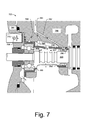
- Fig. 7 is a cross-sectional view of an example of an assembly that includes a bearing cartridge.
- Fig. 8 is a block diagram of an example of a method that includes operating a shaft supported by a rolling element bearing disposed in a floating shell.
- a turbocharger bearing cartridge assembly can include a bearing with an inner race, an outer race and rolling elements disposed between the inner race and the outer race; a journal bearing; and a shell that includes an interior, compressor side annular surface configured to seat the outer race of the bearing and an interior, turbine side annular surface configured to seat the journal bearing.
- a bearing assembly is typically configured for insertion in a bore of a housing of a turbocharger.
- a turbocharger assembly that includes a shell configured to seat a compressor side rolling element bearing and a turbine side journal bearing where the shell includes a compressor side rim and an anti-rotation feature; and a housing that includes a bore configured to receive the shell, an axial face configured to seat the rim of the shell to axially locate the shell in the bore, and an anti-rotation feature configured to cooperate with the anti-rotation feature of the shell to limit rotation of the shell in the bore.
- clearances between the shell and the housing can provide for formation of lubricant films to float the shell in the housing.
- a turbocharger assembly that includes a bearing cartridge with a rimmed shell seating a compressor side rolling element bearing and a turbine side journal bearing; a housing with an axial face and a bore configured to, respectively, axially located and receive the rimmed shell; and a shaft rotatably supported by the rolling element bearing where the shaft includes a finned portion for enhanced heat transfer.
- the rimmed shell includes a rim and a shell body that extends axially away from the rim that seats the compressor side rolling element bearing and the turbine side journal bearing.
- the finned portion of the shaft acts to increase heat transfer between the shaft and lubricant (e.g., at least in part via increased heat transfer area) and reduce temperatures experienced by the compressor side rolling element bearing.
- lubricant e.g., at least in part via increased heat transfer area
- exhaust is the main source of heat.
- a shell is configured to seat a rolling element bearing and a journal bearing and to float in a housing on lubricant squeeze films formed between the shell and housing (e.g., in comparison to conventional approaches that rely on an outer race-housing squeeze film).
- An approach that includes shell-housing squeeze films can reduce angular axial shaft tilt, which, in turn, can improve bearing durability.
- a conventional assembly may have a tilt of about 0.25 degrees whereas, as an example, a shell approach may reduce tilt to about 0.06 degrees (e.g., a reduction of about one-fourth to one-fifth compared to a conventional assembly, which may be achieved by maximum tilt being determined primarily by inside radial clearance of a journal bearing).
- Such an approach can be beneficial as high tilt conditions may be detrimental for tracks of a rolling element bearing (e.g., ball tracks of a ball bearing).
- a compressor side bearing may be able to operate at lower temperatures to reduce thermal stress, reduce risk of coke formation, etc.
- such an approach can optionally eliminate a need for a thrust bearing while benefiting from low power loss/high load capacity of a rolling element bearing (e.g., ball or other type of rolling element), without jeopardizing reliability due to high turbine side temperatures.
- a shell approach can allow for locating a compressor side bearing as far as it can reasonably be from a turbine side exhaust heat source.
- high cost rolling element bearing race materials such as M50 VIM-VAR steel (a through-hardening grade with high hardness and high compressive strength at elevated temperatures), may reasonably be avoided.
- a shaft may be machined or otherwise formed with features that improve heat transfer from the shaft to a cooling fluid (e.g., lubricant).
- a cooling fluid e.g., lubricant
- jet cooling e.g., jet cooling
- jet opening or passage restrictions e.g., length, cross-sectional area, shape, etc.
- turbocharger e.g., which may increase power loss
- a conventional system 100 includes an internal combustion engine 110 and a turbocharger 120.
- the internal combustion engine 110 includes an engine block 118 housing one or more combustion chambers that operatively drive a shaft 112 (e.g., via pistons).
- an intake port 114 provides a flow path for air to the engine block 118 while an exhaust port 116 provides a flow path for exhaust from the engine block 118.
- the turbocharger 120 acts to extract energy from the exhaust and to provide energy to intake air, which may be combined with fuel to form combustion gas.
- the turbocharger 120 includes an air inlet 134, a shaft 122, a compressor 124, a turbine 126, a housing 128 and an exhaust outlet 136.
- the housing 128 may be referred to as a center housing as it is disposed between the compressor 124 and the turbine 126.
- the shaft 122 may be a shaft assembly that includes a variety of components.
- a wastegate valve (or simply wastegate) 135 is positioned proximate to the inlet of the turbine 126. The wastegate valve 135 can be controlled to allow exhaust from the exhaust port 116 to bypass the turbine 126.
- a controller 190 is shown as including one or more processors 192, memory 194 and one or more interfaces 196.
- a controller may include circuitry such as circuitry of an engine control unit.
- Such a controller may include circuitry that provides for reading, writing or reading and writing information (e.g., executable instructions, control instructions, data, etc.) to memory (e.g., a computer-readable storage medium).
- various methods or techniques may optionally be implemented in conjunction with a controller, for example, through control logic. Control logic may depend on one or more engine operating conditions (e.g., turbo rpm, engine rpm, temperature, load, lubricant, cooling, etc.).
- sensors may transmit information to the controller 190 via the one or more interfaces 196.
- Control logic may rely on such information and, in turn, the controller 190 may output control signals to control engine operation.
- the controller 190 may be configured to control lubricant flow, temperature, a variable geometry assembly (e.g., variable geometry compressor or turbine), a wastegate, an electric motor, or one or more other components associated with an engine, a turbocharger (or turbochargers), etc.
- Fig. 2 shows an example of a turbocharger assembly 200 that includes a shaft 220 supported by a compressor side bearing 240 and a turbine side bearing 250 that are located by a shell 260.
- the shell 260 and the bearings 240 and 250 may be referred to as a turbocharger bearing cartridge.
- the shell 260 is positioned in a bore of a housing 280 where a compressor plate 290 acts to axially locate the shell 260 in the bore.
- a thrust collar 230 is rotatably disposed in a bore of the compressor plate 290, which, as described herein, may optionally be part of the bearing 240 (see, e.g., collar 235 of Fig. 5 ).
- a lubricant inlet 281 provides for flow of lubricant into the housing 280 where passages 283 and 287 direct lubricant to annular bore surfaces 286 and 288. While two passages are shown, the housing 280 may include one or more additional passages or, for example, another arrangement of features to direct lubricant to a turbine side bearing and a compressor side bearing.
- various lubricant films may form, including films between the cartridge shell 260 and the plate 290 (f cs-p ), between the cartridge shell 260 and the housing 280 (f cs-h ), between the compressor bearing 240 and the cartridge shell 260 (f cb-cs ), and between the turbine bearing 250 and the shaft 220 (f ts-s ).
- the shell 260 can "float" in the bore of the housing 280 (e.g., provided sufficient lubricant and pressure). Floating can help damp vibration, flow of lubricant, cooling, etc.
- clearances between the shell 260 and the bore of the housing 280 can allow for some small amount of tilt, indicated by a "tilt +" and a "tilt -". Further, clearance between the turbine bearing 250 and the shaft 220 may also allow for some axial tilt. In general, however, as the compressor side bearing 240 is fit radially in the shell 260 (e.g., press-fit), tilting of the compressor side bearing 240 is minimized.
- lubricant may be provided from a pump such as an engine oil pump. After operation ceases or where pumping ceases, lubricant may drain from a housing (e.g., due to gravity), which may result in film thinning and possibly one or more points of contact between a shell and a housing. Upon return to operation, lubricant flow to the housing aims to support various films that allow for a return to a float state of the shell in the housing.
- the shell 260 further includes a prong 272 received by an opening 289 in the housing 280.
- the prong 272 limits or prevents rotation of the shell 260 in the bore of the housing 280.
- Such an arrangement can ensure that lubricant openings of the shell 260 align properly with lubricant passages, etc., to provide for proper flow of lubricant for purposes of lubrication, floating, cooling, damping, or any combination thereof.
- Fig. 3 shows the housing 280 and the shaft 220, with respect to an axial coordinate (z) and a radial coordinate (r).
- a central axis of the shaft 220 aligns substantially with a central axis of the bore of the housing 280, for example, extending between a compressor end 282 and a turbine end 284 and as defined by annular surfaces 286 and 288.
- the annular surface 286 is disposed at a radius r c with an axial width ⁇ z c and the annular surface 288 is disposed at a radius r t with an axial width ⁇ z t .
- the bore of the housing 280 has an axial width ⁇ z ct between the compressor end 282 and the turbine end 284 and an intermediate width ⁇ z i between the surfaces 286 and 288.
- the opening 289 may be defined by one or more dimensions.
- a partial bore e.g., cylindrical in shape
- an opening configured to receive and restrict a prong or other anti-rotation feature may be defined by a width (e.g., ⁇ r ro ), depth and an arc length dimension about an azimuthal coordinate (e.g., measured in degrees about the central axis of the bore).
- the shaft 220 includes a compressor end 222 and a turbine end 224 with a compressor side bearing surface 226 and a turbine side bearing surface 228 disposed therebetween.
- Each of the bearing surfaces 226 and 228 may be defined by a respective diameter (e.g., d c and d t ) and a respective axial length (e.g., ⁇ z c and ⁇ z t ).
- An axial face 225 may mark a change in shaft diameter, for example, to position a race of a compressor side bearing (see, e.g., the bearing 240 of Fig. 2 ).
- a shaft may include fins or other features to increase heat transfer from the shaft to lubricant.
- the shaft 220 includes a series of features 227 that provide additional heat transfer area A1, A2, A3 and AN adjacent respective surfaces S1, S2, S3 and SN.
- the heat transfer areas may be readily formed by machining a rotating shaft and may be formed with curvature to promote lubricant flow, for example, as slow flowing or stationary lubricant may lead to coke formation (e.g., via reactions favored by elevated temperature over time).
- Fig. 3 further shows various temperatures and heat generation terms with respect to the shaft 220.
- Sources of heat include the compressor side bearing (Q BC ), the turbine side bearing (Q BT ) and the exhaust turbine end of the shaft (Q T ).
- bearing power losses e.g., friction
- exhaust provides more heat than that generated by normally operating bearings.
- Lubricant flow is important to cool a shaft and bearings. The difference between lubricant inlet temperature T in and outlet temperature T out is indicative of ability to transfer generated bearing heat and exhaust heat to lubricant.
- shaft features e.g., the features 227) may be provided to enhance such heat transfer.
- enhanced shaft cooling can act to reduce bearing temperature, which, in turn, can improve performance, prolong bearing life, etc. (e.g., via improved lubricant dynamics, reduced coking, etc.).
- Fig. 4 shows various views of the shell 260 of Fig. 2 with respect to a cylindrical (r, z, ⁇ ) coordinate system.
- a shell may be oriented with respect to gravity, for example, to provide for gravity induced flow of lubricant (e.g., from top to bottom openings).
- a housing or housing bore may be oriented with respect to gravity as well.
- the shell 260 includes a compressor end 262, a rim 263, a turbine end 264, an exterior surface 265, an interior axial face 266, an exterior surface 267, an interior axial face 268, an exterior surface 269, a lubricant opening 271, an anti-rotation feature 272, a lubricant opening 273, a deformable or depressible tab 274, a deformable or depressible tab 275, an interior annular surface 276, a lubricant opening 277, an interior annular surface 278 and a lubricant outlet 279 and an example of an alternative lubricant outlet 479.
- a tab may optionally be removable (e.g., via cutting, deformation that leads to detachment, etc.).
- axial dimensions include an axial length ⁇ z c for the compressor side interior annular surface 276, an axial length ⁇ z t for the turbine side interior annular surface 278, an axial intermediate length ⁇ z i between the two annular surfaces 276 and 278, an axial length or thickness ⁇ z r of the rim 263, and an axial lubricant outlet length ⁇ z out for the lubricant outlet 279 and the alternative 479.
- Various radial dimensions are also shown, including a radius r r of the rim 263, a radius r c of the compressor side interior annular surface 276, an upper radius r icu of the axial face 266, a lower radius r icl of the axial face 266, and a radius r t of the turbine side interior annular surface 278.
- the shell 260 is composed of a rim 263 at the compressor end 262, a substantially cylindrical portion defined by the exterior surface 265 having a radius less than the rim 263, a tapering portion defined by the exterior surface 267 that tapers to a substantially cylindrical portion defined by the exterior surface 269 that terminates at the turbine end 264, which includes a rolled edge that forms the interior axial face 268.
- dimensions of various exterior surfaces of the shell 260 and of various surfaces of the housing 280 provide clearances for formation of lubricant films.
- the surface 265 of the shell 260 and the surface 286 of the housing 280 can be dimensioned to provide for formation of a lubricant film, which may act to damp vibrations experienced during operation of a turbocharger.
- the surface 269 of the shell 260 and the surface 288 of the housing 280 can be dimensioned to provide for formation of a lubricant film, which may act to damp vibrations experienced during operation of a turbocharger.
- rim 263 may allow for film formation between the rim 263 and the housing 280 and between the rim 263 and the plate 290. Such films may act to absorb axial thrust forces experienced during operation of a turbocharger (e.g., to reduce part-to-part contact and wear).
- a shell can provide radial surfaces for film formation and axial surfaces for film formation where such films can damp vibration, absorb thrust force, reduce wear, etc.
- lubricant outlet 479 of Fig. 4 by extending it to the interior annular surface 276, lubricant may more readily drain from the shell 260, compared to the lubricant outlet 279 as the shoulder formed by stepping from the radius r c to r icl may act to retain some lubricant.
- the alternative outlet 479 is provided as an example, as other arrangement may include one or more openings located along the step, etc.
- Fig. 5 shows various views of the shell 260 and bearings 240 and 250 of Fig. 2 .
- the bearings 240 and 250 are shown as axially aligned with the shell 260, but for an alternative example of the bearing 240 that includes an inner race with a thrust collar 235.
- the bearing 240 includes an inner race 243, an inner race 245, rolling elements 247 and an outer race 249.
- the bearing 240 has axial faces 242 and 244 as well as a radial surface 246.
- the bearing 240 may be symmetric or asymmetric; noting that a symmetric bearing can facilitate assembly (e.g., by providing two possible orientations).
- the alternative example of the bearing 240 with the thrust collar 235 is asymmetric, yet, depending on dimensions, may be capable of only one orientation upon assembly. As shown in the example of Fig.
- the thrust collar 235 includes an axial thrust face 237 at one end and a seat 239 at an opposite end, which cooperates with the inner race 245 for seating rolling elements (see, e.g., rolling element 247), as well as an annular groove 238 for seating a seal element (e.g., a ring).
- the components 235 and 245 may be press-fit to a shaft and, during operation, rotate with the shaft.
- a thrust collar serves as an inner race, such an approach can reduce number of components. While balls are shown as rolling elements 247, other types of rolling elements may be provided (e.g., cylinders, etc.).
- the bearing 250 includes one or more lubricant openings 255-1 and 255-2, which are aligned with an annular groove 257 and provide for flow of lubricant to an interior journal surface 258 (e.g., fed from the lubricant opening 277 of the shell 260).
- the bearing 250 includes two axial faces 252 and 254 as well as a radial surface 256.
- dashed lines illustrate various openings 255-1, 255-2, 255-3 and 255-4 and the annular groove 257.
- a bearing with lubricant passages or features that differ from one or more of those of the example bearing 250 of Fig. 5 may be suitable for use with the shell 260.
- Assembly of a bearing cartridge includes locating the bearings 240 and 250 in the shell 260.
- the outer race 249 of the bearing 240 can be located radially by the interior annular surface 276 of the shell 260 and can optionally be located axially by the interior axial face 266 while the journal bearing 250 can be located radially by the interior annular surface 278 of the shell 260 and can optionally be located axially by the interior axial face 268 and optionally by deformation of the tab 275.
- one or both of the bearings 240 and 250 can be located in the shell 260 in a manner that prevents rotation of the outer race 249 of the rolling element bearing 240 or rotation of the journal bearing 250.
- Such an approach acts to transfer a lubricant squeeze film or film from bearing surfaces to shell surfaces.
- Fig. 6 shows various views of the shell 260 with optional lubricant channels 666 and the bearing 240 with optional lubricant channels 642 and 644.
- An assembly may include a shell with lubricant channels, a bearing with lubricant channels or a shell with lubricant channels and a bearing with lubricant channels.
- alignment may be facilitate via one or more markings on an outer race, a shell or an outer race and a shell. For example, in Fig.
- a marking 241 appears on the face 242 of the outer race 249, which may be for alignment with the anti-rotation feature 272 of the shell 260.
- degree of alignment (or misalignment) of passages may determine, at least in part, lubricant flow dynamics from an opening in a shell (e.g., the opening 271) and between a face of an outer race (e.g., the face 244) that abuts a face of the shell (e.g., the face 266).
- the lubricant channels 666 exist over an arc portion of the axial face 266 of the shell 260. Such channels allow for flow of lubricant from the opening 271 to the rolling elements 247 of the bearing 240.
- the outer race 249 of the bearing 240 may include lubricant channels.
- the outer race 249 may include lubricant channels 644 on one axial face 244 (e.g., as an asymmetric bearing) or may include lubricant channels 642 and 644 on both axial faces 242 and 244 (e.g., as a symmetric bearing).
- the channels 642 or 644 are located adjacent the axial face 266 of the shell 260, which may also include one or more channels 666.
- a spacing mechanism may be provided to maintain a space between the outer race 249 of the bearing 240 and the axial face 266 of the shell 260 where such a space allows for flow of lubricant to rolling elements 247 of the bearing 240.
- the inner race 243 may optionally include a thrust collar (see, e.g., the thrust collar 235 of Fig. 5 ).
- Fig. 7 shows an example of an assembly 700 that includes a bearing cartridge.
- the assembly 700 includes a housing 780 with a lubricant inlet 781 in fluid communication with lubricant passages 783, 785 and 787.
- a jet may be provided to direct lubricant to a portion of a shaft.
- the passage 785 can direct lubricant to a finned portion 227 of the shaft 220.
- Fig. 7 also shows a shell 760 as including at least one channel 666 for flow of lubricant to rolling elements 247. Further, a deformable or depressible tab 775 is shown in an undepressed position, as the journal bearing 250 may be press-fit or otherwise not require axial location along its compressor facing face 252.
- the shell 780 includes an opening 772 configured to receive a post 789 extending axially outward from an axial face of the housing 780.
- openings may exist in both the shell and the housing where, for example, a plate (e.g., the plate 290) includes a post that acts to limit rotation of the shell in the housing upon receipt of the post by both openings. While some examples are given, various other types of anti-rotation mechanisms may be implemented.
- Fig. 8 shows an example of a method 800.
- the method 800 includes a provision block 822 for providing a floating shell (e.g., configured to float in a bore of a housing), a location block 824 for locating a journal bearing in the shell, a location block 826 for locating a rolling element bearing in the shell and an operation block 828 for operating a shaft supported by the rolling element bearing.
- a method can further include deforming or depressing a tab of the shell to locate the journal bearing in the shell.
- a method can include providing lubricant, forming one or more films between a housing and a shell and floating the shell in the housing while also providing lubricant to a rolling element bearing and a journal bearing.
- Such a method can further include directing lubricant to a portion of a rotating shaft where that portion may include features to enhance heat transfer (e.g., fins, surfaces with varying diameter over axial distance, etc.).
- a turbocharger bearing cartridge can include a bearing with an inner race (optionally a multi-piece inner race), an outer race and rolling elements disposed between the inner race and the outer race; a journal bearing (optionally a unitary piece); and a shell that includes an interior, compressor side annular surface configured to seat the outer race of the bearing and an interior, turbine side annular surface configured to seat the journal bearing.
- a bearing with an inner race (optionally a multi-piece inner race), an outer race and rolling elements disposed between the inner race and the outer race; a journal bearing (optionally a unitary piece); and a shell that includes an interior, compressor side annular surface configured to seat the outer race of the bearing and an interior, turbine side annular surface configured to seat the journal bearing.
- Such a cartridge can include an anti-rotation feature to limit rotation of the shell in a bore of a housing of a turbocharger.
- a shell can include a compressor side rim.
- a rim may be configured to axially locate the shell in a bore of a housing of a turbocharger.
- a shell may include a rolled edge.
- Such an edge may be configured to axially locate a journal bearing or, depending on requirements (e.g., performance, cost, etc.), optionally another type of bearing or a portion thereof (e.g., an outer race of a rolling element bearing).
- a shell can include an axial face disposed adjacent an interior, compressor side annular surface where, for example, the axial face is configured to locate an outer race of a bearing.
- Such an axial face may include at least one lubricant channel configured to provide for flow of lubricant to rolling elements of the bearing.
- an outer race of a bearing can include at least one lubricant channel configured to provide for flow of lubricant to rolling elements of the bearing.
- a shell may include at least one deformable or depressible tab.
- a deformable tab may be a journal bearing locating tab.
- a deformable tab may be a lubricant inlet tab.
- a shell can include a lubricant outlet disposed between an interior, compressor side annular surface and an interior, turbine side annular surface.
- such a bearing may include an inner race with a thrust collar, configured to extend axially outwardly away from the shell.
- Such an inner race may be composed of two pieces, a unitary inner race-thrust collar piece and another unitary inner race piece.
- the outer race or the inner race is typically formed from two or more pieces (e.g., a process that includes providing race(s), positioning rolling elements, encapsulating elements).
- a turbocharger bearing cartridge can optionally accommodate a shaft that includes a surface to cooperate with an inner race of a rolling element bearing, a surface to cooperate with a journal bearing and heat transfer surfaces, each surface of varying diameter, located therebetween.
- a bearing cartridge can include an interior, compressor side annular surface with a lubricant opening and an interior, turbine side annular surface with a lubricant opening.
- a turbocharger assembly can include a shell configured to seat a compressor side rolling element bearing and a turbine side journal bearing where the shell includes a compressor side rim and an anti-rotation feature; and a housing that includes a bore configured to receive the shell, an axial face configured to seat the rim of the shell to axially locate the shell in the bore, and an anti-rotation feature configured to cooperate with the anti-rotation feature of the shell to limit rotation of the shell in the bore.
- clearances between the shell and the housing can provide for formation of lubricant films to float the shell in the housing.
- a turbocharger assembly can include a bearing cartridge that includes a rimmed shell seating a compressor side rolling element bearing and a turbine side journal bearing; a housing that includes an axial face and a bore configured to, respectively, axially located and receive the rimmed shell; and a shaft rotatably supported by the rolling element bearing where the shaft includes a finned portion for enhanced heat transfer.
- various acts may be performed by a controller (see, e.g., the controller 190 of Fig. 1 ), which may be a programmable control configured to operate according to instructions.
- one or more computer-readable media may include processor-executable instructions to instruct a computer (e.g., controller or other computing device) to perform one or more acts described herein.
- a computer-readable medium may be a storage medium (e.g., a device such as a memory chip, memory card, storage disk, etc.).
- a controller may be able to access such a storage medium (e.g., via a wired or wireless interface) and load information (e.g., instructions and/or other information) into memory (see, e.g., the memory 194 of Fig. 1 ).
- a controller may be an engine control unit (ECU) or other control unit.
- ECU engine control unit
Landscapes
- Engineering & Computer Science (AREA)
- General Engineering & Computer Science (AREA)
- Mechanical Engineering (AREA)
- Chemical & Material Sciences (AREA)
- Chemical Kinetics & Catalysis (AREA)
- General Chemical & Material Sciences (AREA)
- Combustion & Propulsion (AREA)
- Supercharger (AREA)
- Rolling Contact Bearings (AREA)
Applications Claiming Priority (1)
| Application Number | Priority Date | Filing Date | Title |
|---|---|---|---|
| US13/149,439 US9046036B2 (en) | 2011-05-31 | 2011-05-31 | Bearing assembly |
Publications (1)
| Publication Number | Publication Date |
|---|---|
| EP2530254A2 true EP2530254A2 (de) | 2012-12-05 |
Family
ID=46146680
Family Applications (1)
| Application Number | Title | Priority Date | Filing Date |
|---|---|---|---|
| EP12167954A Withdrawn EP2530254A2 (de) | 2011-05-31 | 2012-05-14 | Lageranordnung |
Country Status (3)
| Country | Link |
|---|---|
| US (1) | US9046036B2 (de) |
| EP (1) | EP2530254A2 (de) |
| CN (1) | CN102808663A (de) |
Cited By (5)
| Publication number | Priority date | Publication date | Assignee | Title |
|---|---|---|---|---|
| EP3073135A1 (de) * | 2015-03-27 | 2016-09-28 | Pratt & Whitney Canada Corp. | Lagersystem mit lagerdämpfer |
| EP3081769A1 (de) * | 2015-04-12 | 2016-10-19 | Honeywell International Inc. | Lageranordnung für turbolader |
| US9695708B2 (en) | 2015-04-12 | 2017-07-04 | Honeywell International Inc. | Turbocharger spring assembly |
| US10208623B2 (en) | 2015-04-12 | 2019-02-19 | Garrett Transportation I Inc. | Turbocharger bearing assembly |
| EP4206443A1 (de) * | 2021-12-29 | 2023-07-05 | Garrett Transportation I Inc. | Flexible lagerkartusche für turbolader |
Families Citing this family (8)
| Publication number | Priority date | Publication date | Assignee | Title |
|---|---|---|---|---|
| US8991176B2 (en) * | 2012-03-28 | 2015-03-31 | GM Global Technology Operations LLC | Fluid drive mechanism for turbocharger |
| US9163717B2 (en) * | 2012-04-30 | 2015-10-20 | United Technologies Corporation | Multi-piece fluid manifold for gas turbine engine |
| JP6253024B2 (ja) * | 2014-10-24 | 2017-12-27 | 三菱重工業株式会社 | ターボチャージャ |
| CN107532652B (zh) * | 2015-06-04 | 2019-06-28 | 三菱重工发动机和增压器株式会社 | 轴承装置及增压器 |
| DE102015215296B4 (de) * | 2015-08-11 | 2020-10-22 | Aktiebolaget Skf | Lageranordnung und Lagerring zum drehbeweglichen Lagern eines ersten Bauteils gegenüber einem zweiten Bauteil sowie Schraubenkompressor mit der Lageranordnung oder dem Lagerring |
| CN105526261B (zh) * | 2016-01-28 | 2018-02-13 | 陈岩 | 涡轮与轴离心共同作用下的双轴承循环油润滑系统 |
| US10316742B2 (en) * | 2016-05-13 | 2019-06-11 | Garrett Transportation I Inc. | Turbocharger assembly |
| EP4108943B1 (de) * | 2017-11-24 | 2023-12-27 | BRP-Rotax GmbH & Co. KG | Kraftfahrzeugkraftwerk bestehend aus einem verbrennungsmotor mit turbolader |
Family Cites Families (14)
| Publication number | Priority date | Publication date | Assignee | Title |
|---|---|---|---|---|
| US3411706A (en) * | 1966-08-24 | 1968-11-19 | Wallace Murray Corp | Bearing durability enhancement device for turbocharger |
| DE2242734A1 (de) * | 1972-08-31 | 1974-03-21 | Motoren Turbinen Union | Lagerung fuer waermekraftmaschinen |
| US4091663A (en) * | 1975-10-22 | 1978-05-30 | Avco Corporation | Torque indicating device |
| US4641977A (en) * | 1983-04-11 | 1987-02-10 | Woollenweber William E | Bearing system |
| JPS61142329A (ja) * | 1984-12-14 | 1986-06-30 | ザ ギヤレツト コーポレーシヨン | ターボチヤージヤの組立方法およびターボチヤージヤ |
| US5025629A (en) * | 1989-03-20 | 1991-06-25 | Woollenweber William E | High pressure ratio turbocharger |
| US5094587A (en) * | 1990-07-25 | 1992-03-10 | Woollenweber William E | Turbine for internal combustion engine turbochargers |
| JP2584936Y2 (ja) | 1992-08-19 | 1998-11-11 | 日本精工株式会社 | ターボチャージャー用玉軸受 |
| US5967762A (en) * | 1996-03-18 | 1999-10-19 | Turbonetics, Inc. | Turbocharger for high performance internal combustion engines |
| US5870894A (en) * | 1996-07-16 | 1999-02-16 | Turbodyne Systems, Inc. | Motor-assisted supercharging devices for internal combustion engines |
| US6032466A (en) * | 1996-07-16 | 2000-03-07 | Turbodyne Systems, Inc. | Motor-assisted turbochargers for internal combustion engines |
| US5890881A (en) * | 1996-11-27 | 1999-04-06 | Alliedsignal Inc. | Pressure balanced turbocharger rotating seal |
| US6220829B1 (en) * | 1998-10-05 | 2001-04-24 | Glenn F. Thompson | Turbocharger rotor with low-cost ball bearing |
| US7104693B2 (en) * | 2004-06-28 | 2006-09-12 | Honeywell International, Inc. | Multi-thickness film layer bearing cartridge and housing |
-
2011
- 2011-05-31 US US13/149,439 patent/US9046036B2/en not_active Expired - Fee Related
-
2012
- 2012-05-14 EP EP12167954A patent/EP2530254A2/de not_active Withdrawn
- 2012-05-30 CN CN2012101725860A patent/CN102808663A/zh active Pending
Non-Patent Citations (1)
| Title |
|---|
| None |
Cited By (7)
| Publication number | Priority date | Publication date | Assignee | Title |
|---|---|---|---|---|
| EP3073135A1 (de) * | 2015-03-27 | 2016-09-28 | Pratt & Whitney Canada Corp. | Lagersystem mit lagerdämpfer |
| US9752616B2 (en) | 2015-03-27 | 2017-09-05 | Pratt & Withney Canada Corp. | Bearing system with bearing damper |
| EP3081769A1 (de) * | 2015-04-12 | 2016-10-19 | Honeywell International Inc. | Lageranordnung für turbolader |
| US9695708B2 (en) | 2015-04-12 | 2017-07-04 | Honeywell International Inc. | Turbocharger spring assembly |
| US9976476B2 (en) | 2015-04-12 | 2018-05-22 | Honeywell International Inc. | Turbocharger bearing assembly |
| US10208623B2 (en) | 2015-04-12 | 2019-02-19 | Garrett Transportation I Inc. | Turbocharger bearing assembly |
| EP4206443A1 (de) * | 2021-12-29 | 2023-07-05 | Garrett Transportation I Inc. | Flexible lagerkartusche für turbolader |
Also Published As
| Publication number | Publication date |
|---|---|
| US20120308366A1 (en) | 2012-12-06 |
| CN102808663A (zh) | 2012-12-05 |
| US9046036B2 (en) | 2015-06-02 |
Similar Documents
| Publication | Publication Date | Title |
|---|---|---|
| US9046036B2 (en) | Bearing assembly | |
| US9963998B2 (en) | Assembly with bearings and spacer | |
| EP2850300B1 (de) | Turbolader mit gleitlager | |
| US8858173B2 (en) | Bearing assembly with damping features | |
| EP2573362B1 (de) | Turbolader mit einer Hülse | |
| EP3244027B1 (de) | Turboladeranordnung | |
| US9695708B2 (en) | Turbocharger spring assembly | |
| CN101568736A (zh) | 用于涡轮增压器轴的浮动轴承机座 | |
| EP3081769B1 (de) | Lageranordnung für turbolader | |
| US10208623B2 (en) | Turbocharger bearing assembly | |
| EP2706197B1 (de) | Scheibe zum Positionieren des Lageraussenrings | |
| EP2163731A1 (de) | Hochleistungsaxiallager | |
| US8186947B2 (en) | Conical pin to maintain bearing system | |
| CN101672326A (zh) | 涡轮增压器混合陶瓷球轴承及其设计方法 | |
| CN102163887B (zh) | 高速电机用静压升举与滚动环轴承混合支承及该旋转机械 | |
| JP2005076463A (ja) | ターボチャージャの軸受装置 |
Legal Events
| Date | Code | Title | Description |
|---|---|---|---|
| PUAI | Public reference made under article 153(3) epc to a published international application that has entered the european phase |
Free format text: ORIGINAL CODE: 0009012 |
|
| 17P | Request for examination filed |
Effective date: 20120514 |
|
| AK | Designated contracting states |
Kind code of ref document: A2 Designated state(s): AL AT BE BG CH CY CZ DE DK EE ES FI FR GB GR HR HU IE IS IT LI LT LU LV MC MK MT NL NO PL PT RO RS SE SI SK SM TR |
|
| AX | Request for extension of the european patent |
Extension state: BA ME |
|
| STAA | Information on the status of an ep patent application or granted ep patent |
Free format text: STATUS: THE APPLICATION HAS BEEN WITHDRAWN |
|
| 18W | Application withdrawn |
Effective date: 20150910 |