EP2530802B1 - Leistungsteuervorrichtung, Leistungsverwaltungsvorrichtung und Leistungsverwaltungssystem - Google Patents
Leistungsteuervorrichtung, Leistungsverwaltungsvorrichtung und Leistungsverwaltungssystem Download PDFInfo
- Publication number
- EP2530802B1 EP2530802B1 EP12169183.6A EP12169183A EP2530802B1 EP 2530802 B1 EP2530802 B1 EP 2530802B1 EP 12169183 A EP12169183 A EP 12169183A EP 2530802 B1 EP2530802 B1 EP 2530802B1
- Authority
- EP
- European Patent Office
- Prior art keywords
- power
- electricity
- control device
- information
- power control
- Prior art date
- Legal status (The legal status is an assumption and is not a legal conclusion. Google has not performed a legal analysis and makes no representation as to the accuracy of the status listed.)
- Not-in-force
Links
Images


Classifications
-
- G—PHYSICS
- G05—CONTROLLING; REGULATING
- G05F—SYSTEMS FOR REGULATING ELECTRIC OR MAGNETIC VARIABLES
- G05F1/00—Automatic systems in which deviations of an electric quantity from one or more predetermined values are detected at the output of the system and fed back to a device within the system to restore the detected quantity to its predetermined value or values, i.e. retroactive systems
- G05F1/66—Regulating electric power
-
- H—ELECTRICITY
- H02—GENERATION; CONVERSION OR DISTRIBUTION OF ELECTRIC POWER
- H02J—ELECTRIC POWER NETWORKS; CIRCUIT ARRANGEMENTS OR SYSTEMS FOR SUPPLYING OR DISTRIBUTING ELECTRIC POWER; SYSTEMS FOR STORING ELECTRIC ENERGY
- H02J3/00—Circuit arrangements for AC mains or AC distribution networks
- H02J3/008—Circuit arrangements for power supply or distribution technologies responsive to energy trading
-
- H—ELECTRICITY
- H02—GENERATION; CONVERSION OR DISTRIBUTION OF ELECTRIC POWER
- H02J—ELECTRIC POWER NETWORKS; CIRCUIT ARRANGEMENTS OR SYSTEMS FOR SUPPLYING OR DISTRIBUTING ELECTRIC POWER; SYSTEMS FOR STORING ELECTRIC ENERGY
- H02J3/00—Circuit arrangements for AC mains or AC distribution networks
- H02J3/28—Arrangements for balancing of the load in networks by storage of energy
- H02J3/32—Arrangements for balancing of the load in networks by storage of energy using batteries or super capacitors with converting means
-
- H—ELECTRICITY
- H04—ELECTRIC COMMUNICATION TECHNIQUE
- H04L—TRANSMISSION OF DIGITAL INFORMATION, e.g. TELEGRAPHIC COMMUNICATION
- H04L63/00—Network architectures or network communication protocols for network security
- H04L63/04—Network architectures or network communication protocols for network security for providing a confidential data exchange among entities communicating through data packet networks
- H04L63/0428—Network architectures or network communication protocols for network security for providing a confidential data exchange among entities communicating through data packet networks wherein the data content is protected, e.g. by encrypting or encapsulating the payload
-
- H—ELECTRICITY
- H04—ELECTRIC COMMUNICATION TECHNIQUE
- H04L—TRANSMISSION OF DIGITAL INFORMATION, e.g. TELEGRAPHIC COMMUNICATION
- H04L63/00—Network architectures or network communication protocols for network security
- H04L63/08—Network architectures or network communication protocols for network security for authentication of entities
- H04L63/0876—Network architectures or network communication protocols for network security for authentication of entities based on the identity of the terminal or configuration, e.g. MAC address, hardware or software configuration or device fingerprint
-
- H—ELECTRICITY
- H04—ELECTRIC COMMUNICATION TECHNIQUE
- H04L—TRANSMISSION OF DIGITAL INFORMATION, e.g. TELEGRAPHIC COMMUNICATION
- H04L63/00—Network architectures or network communication protocols for network security
- H04L63/04—Network architectures or network communication protocols for network security for providing a confidential data exchange among entities communicating through data packet networks
- H04L63/0428—Network architectures or network communication protocols for network security for providing a confidential data exchange among entities communicating through data packet networks wherein the data content is protected, e.g. by encrypting or encapsulating the payload
- H04L63/0435—Network architectures or network communication protocols for network security for providing a confidential data exchange among entities communicating through data packet networks wherein the data content is protected, e.g. by encrypting or encapsulating the payload wherein the sending and receiving network entities apply symmetric encryption, i.e. same key used for encryption and decryption
-
- H—ELECTRICITY
- H04—ELECTRIC COMMUNICATION TECHNIQUE
- H04L—TRANSMISSION OF DIGITAL INFORMATION, e.g. TELEGRAPHIC COMMUNICATION
- H04L63/00—Network architectures or network communication protocols for network security
- H04L63/08—Network architectures or network communication protocols for network security for authentication of entities
- H04L63/0869—Network architectures or network communication protocols for network security for authentication of entities for achieving mutual authentication
-
- Y—GENERAL TAGGING OF NEW TECHNOLOGICAL DEVELOPMENTS; GENERAL TAGGING OF CROSS-SECTIONAL TECHNOLOGIES SPANNING OVER SEVERAL SECTIONS OF THE IPC; TECHNICAL SUBJECTS COVERED BY FORMER USPC CROSS-REFERENCE ART COLLECTIONS [XRACs] AND DIGESTS
- Y04—INFORMATION OR COMMUNICATION TECHNOLOGIES HAVING AN IMPACT ON OTHER TECHNOLOGY AREAS
- Y04S—SYSTEMS INTEGRATING TECHNOLOGIES RELATED TO POWER NETWORK OPERATION, COMMUNICATION OR INFORMATION TECHNOLOGIES FOR IMPROVING THE ELECTRICAL POWER GENERATION, TRANSMISSION, DISTRIBUTION, MANAGEMENT OR USAGE, i.e. SMART GRIDS
- Y04S40/00—Systems for electrical power generation, transmission, distribution or end-user application management characterised by the use of communication or information technologies, or communication or information technology specific aspects supporting them
- Y04S40/20—Information technology specific aspects, e.g. CAD, simulation, modelling, system security
-
- Y—GENERAL TAGGING OF NEW TECHNOLOGICAL DEVELOPMENTS; GENERAL TAGGING OF CROSS-SECTIONAL TECHNOLOGIES SPANNING OVER SEVERAL SECTIONS OF THE IPC; TECHNICAL SUBJECTS COVERED BY FORMER USPC CROSS-REFERENCE ART COLLECTIONS [XRACs] AND DIGESTS
- Y04—INFORMATION OR COMMUNICATION TECHNOLOGIES HAVING AN IMPACT ON OTHER TECHNOLOGY AREAS
- Y04S—SYSTEMS INTEGRATING TECHNOLOGIES RELATED TO POWER NETWORK OPERATION, COMMUNICATION OR INFORMATION TECHNOLOGIES FOR IMPROVING THE ELECTRICAL POWER GENERATION, TRANSMISSION, DISTRIBUTION, MANAGEMENT OR USAGE, i.e. SMART GRIDS
- Y04S50/00—Market activities related to the operation of systems integrating technologies related to power network operation or related to communication or information technologies
- Y04S50/10—Energy trading, including energy flowing from end-user application to grid
Definitions
- the present technology relates to a power control device, a power management device and a power management system.
- the energy storage equipment which is equipped with storage batteries that can charge and discharge electricity, can obtain power through power generation equipment utilizing natural energies or can store electricity that is purchased from an electricity company.
- an energy storage system has been proposed (refer to Japanese Patent Application Publication No. JP-A-2002-233053 , for example) in which fluctuations in electricity prices are predicted in accordance with an algorithm, electricity is purchased and stored in energy storage equipment when a low price is predicted, and the electricity stored in the energy storage equipment is sold when a high price is predicted, thus attempting to obtain a profit.
- US 2009/292918 describes an authentication system provided with a server device for generating a random number used for authentication and check data obtained by encrypting the random number using an encryption key, an authentication device for authenticating a device to be authenticated by transmitting the random number transmitted from the server device to the device to be authenticated and comparing reply data transmitted from the device to be authenticated with check data transmitted from the server device, and the device to be authenticated for encrypting the random number transmitted from the authentication device using the encryption key and transmitting the encrypted random number as reply data.
- the present technology provides a power control device, a power management device and a power management system that are capable of increasing reliability of energy storage equipment and a management device that manages the energy storage equipment.
- FIG. 1 is a diagram showing an overall configuration of a power management system according to the present technology.
- the power management system is connected to power generation equipment 40.
- the power management system includes a power control device 10 that forms energy storage equipment 100 and a power/point management server 200.
- the power/point management server 200 issues points in accordance with an instruction of a power supply destination by the energy storage equipment 100, and in accordance with an amount of electricity stored in the energy storage equipment 100.
- the power/point management server 200 corresponds to a power management device within the scope of the appended claims.
- the power management system is a system that intends to obtain higher profits by purchasing electricity from an electricity market when an electricity price is low in the electricity market, such as at night etc. and storing the electricity, and by selling the electricity to the electricity market when the electricity price is high. Additionally, profits are obtained by charging the energy storage equipment 100 utilizing electricity obtained from the power generation equipment 40, and by selling the electricity on the electricity market.
- the electricity market is a market that is formed by energy trading between persons wishing to sell electricity and persons wishing to purchase electricity.
- public electricity companies monopolized the supply of electricity in each region, but in recent years, there has been an increase in movement towards deregulation so that electricity can be freely bought and sold by persons other than existing electricity companies.
- the energy storage equipment 100 has a storage battery module that can store electricity, and is equipment for energy storage that is capable of charging and discharging electricity.
- the energy storage equipment 100 is installed in a private household, in collective housing such as an apartment block, or in buildings and facilities of companies or various organizations.
- the energy storage equipment 100 is provided with the power control device 10 that performs power control, such as charging the storage battery module and discharging electricity from the storage battery module.
- the energy storage equipment 100 is connected to a power network, and performs charging using power from the power network and discharging to the power network in accordance with management by the power/point management server 200.
- the energy storage equipment 100 and the power control device 10 will be explained in detail later. Note that, in the following explanation, a party that owns the energy storage equipment 100 will be referred to as an energy storage equipment owner, irrespective of owner type, such as a corporation or a private household etc.
- the power/point management server 200 is connected to the power control device 10 via a network, and is a server that issues points with respect to each energy storage equipment owner in accordance with an amount of electricity stored in the energy storage equipment 100.
- the power/point management server 200 is connected to the electricity market via a network, and also acquires an electricity price in the electricity market. Based on that electricity price, the power/point management server 200 issues power supply commands to the power control device 10 to perform charging or discharging of electricity etc.
- the charging of the energy storage equipment 100 is performed using electricity obtained from the power generation equipment 40, and electricity is sold to the electricity market by discharging electricity from the energy storage equipment 100. Further, the charging of the energy storage equipment 100 may be performed by purchasing electricity from the electricity market based on the management by the power/point management server 200.
- the power/point management server 200 is installed in a building or facility of a company or an operator (hereinafter referred to as a point issuer) that provides a point service to the energy storage equipment owner. Electricity is stored in the energy storage equipment 100 owned by the energy storage equipment owner, but buying and selling of electricity by the charging and discharging of the energy storage equipment 100 is performed based on the management by the power/point management server 200. Therefore, the point issuer is responsible for the electricity trading on the electricity market. The point issuer sells the electricity from the power generation equipment 40 and the electricity stored by the energy storage equipment 100 on the electricity market, and acquires a fee in accordance with the electricity price in the electricity market, thus obtaining a profit. It is preferable for the power/point management server 200 to have a plurality of the energy storage equipment under its management.
- the energy storage equipment owner can participate in the electricity market without concern for the electricity price in the electricity market.
- Points are awarded by the power/point management server 200 in accordance with the amount of electricity stored in the energy storage equipment 100. As will be explained later, these points can be exchanged for goods and services and the energy storage equipment owner can obtain a profit in this way. In this way, with the present technology, the points act just like currency in accordance with the amount of electricity stored.
- an individual contract may be concluded between the energy storage equipment owner and the point issuer.
- the contract may establish whether or not the electricity obtained from the power generation equipment 40 and the electricity stored in the storage battery module can be used by the energy storage equipment owner as power to operate his or her own electrical devices (hereinafter referred to as home consumption), whether or not the energy storage equipment owner can sell electricity freely of his or her own will, whether or not charging of the storage battery module can be performed using late-night electricity when the electricity price is cheap, and so on.
- the contract it is preferable for the contract to establish which command takes priority when a command from the power/point management server 200 to charge or discharge electricity is issued while the power is being used for home consumption on the command of the energy storage equipment owner, or while electricity is being sold at the will of the energy storage equipment owner.
- the contract it is preferable for the contract to establish whether or not the energy storage equipment owner can perform charging or discharging of electricity at his or her own will when a command is issued by the power/point management server 200 to stop operation of the energy storage equipment 100.
- This type of individual contract between the energy storage equipment owner and the point issuer is concluded, for example, by the point issuer presenting a plurality of contracts to the energy storage equipment owner and by the energy storage equipment owner selecting one of the contracts.
- the power management system is configured in the manner described above, and, in the power management system, in order to use the points issued to the energy storage equipment owner, it is preferable for there to be a point exchanger and a goods/services provider.
- the point exchanger is a party that opens an exchange at which the points held by the energy storage equipment owner can be exchanged with the goods and services provided by the goods/services provider, and thus exchanges the points for the goods and services in accordance with the wishes of the energy storage equipment owner.
- the exchange may be an actual store or commercial facility, or may provide goods and services through electronic information exchange, such as by an electronic trading server or the like.
- the point exchanger obtains a fee from the point issuer by ceding, to the point issuer, the points that are held by the point exchanger as a result of the trade of the points for the goods and services. In this way, the point exchanger can obtain a profit.
- An exchange rate between the points and the fee may be established in advance between the point issuer and the point exchanger. It should be noted that the point issuer and the point exchanger can be the same party. In this case, the exchange of the fee for the points is not necessary.
- the goods/services provider provides the goods and services to the point exchanger.
- the point exchanger exchanges the points held by the energy storage equipment owner for the goods and services
- the goods/services provider receives, from the point exchanger, a fee that corresponds to the exchanged points. In this way, the goods/services provider can obtain a profit.
- the goods and services are goods and services that provide a physical or emotional effect or satisfaction, among which tangible entities are the goods, and intangible entities, of which nothing remains after sale and purchase, are the services.
- the goods include, for example, commodities, vouchers and the like. More specifically, the commodities are, for example, everyday necessities, household electrical appliances, electronic devices, foodstuffs and the like.
- the vouchers are, for example, gift certificates, beer certificates, travel tickets, book tokens, air tickets, tickets to events and so on.
- the services include leisure services, medical services, accommodation services, educational services, transportation services, dining out services, consultancy services and so on. In addition, it may be possible to exchange the points for points of other point services, such as mileage points and the like.
- the goods and services are not limited to the above-described examples, and may be anything that is an object of economic trading.
- the number of points necessary in exchange for the various goods and services provided by the goods/services provider may be determined by the goods/services provider based on the exchange rate between the points and the fee, the exchange rate being established between the point issuer and the point exchanger.
- the goods/services provider and the point exchanger may be the same party.
- the goods/services provider, the point issuer and the point exchanger may be the same party.
- the goods and services are provided to the energy storage equipment owner via the point exchanger.
- a method of providing the goods and services is not limited to the above example.
- the energy storage equipment owner may visit the store etc. and the energy storage equipment owner may exchange points with the goods/services provider for the goods and services on sale at the store etc. Then, the goods/services provider may pass on the points obtained through the point exchange to the point issuer and may receive a fee that accords with the number of points.
- the goods and services exchange When the goods and services exchange is the electronic trading server, the goods and services may be directly provided to the energy storage equipment owner from the goods/services provider.
- the goods may be, for example, content that can be provided via a network, such as video, music, electronic books and the like. In this case, these goods may be provided directly from the goods/services provider to the energy storage equipment owner via the network.
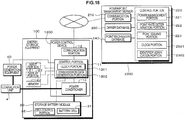
- FIG. 2 is a block diagram showing the configuration of the power control device 10 and the energy storage equipment 100. Note that the power generation equipment 40 that performs power generation is connected to the energy storage equipment 100, but the power control device 10 and the energy storage equipment 100 can function without the power generation equipment 40.
- thick lines indicate DC power lines
- thin lines indicate AC power lines
- broken lines indicate transmission lines for control signals and information signals.
- the energy storage equipment 100 is formed of the power control device 10 and a storage battery module 30.
- the storage battery module 30 includes a battery cell 31 that stores electricity and a cell control portion 32 that performs management control of the battery cell 31.
- the battery cell 31 may adopt any form of battery as long as it can be charged and discharged, such as a lithium-ion secondary battery, a lithium-ion polymer secondary battery and a nickel hydrogen battery etc. Note that, in FIG. 2 , the battery cell 31 is shown by one block, but a number of the battery cells 31 is not limited to one, and a plurality of battery cells 31 may be used.
- the cell control portion 32 includes, for example, a central processing unit (CPU), a random access memory (RAM), a read only memory (ROM), and a sensor etc.
- the cell control portion 32 measures the amount of electricity stored in the storage battery module 30. Further, along with performing management of the battery cell 31, the cell control portion 32 transmits, to a control portion 11 of the power control device 10, information indicating the state of the battery cell 31.
- the power control device 10 includes the control portion 11, a communication portion 12 and a power conditioner 13.
- the power control device 10 performs power control of the energy storage equipment 100, such as charging and discharging, in accordance with the management of the power/point management server 200 that is installed on the point issuer side.
- the control portion 11 is connected to the communication portion 12 and the power conditioner 13.
- the control portion 11 is formed, for example, of a CPU, a RAM and a ROM. Programs read by the CPU are stored in the ROM.
- the RAM is used as a work area of the CPU.
- the CPU executes various processing based on the programs stored in the ROM, and thus performs control of the whole power control device 10.
- the power control device 10 transmits control signals in response to commands from the power/point management server 200 that are received by the communication portion 12.
- the commands include a command that instructs charging (hereinafter referred to as a charge command), a command that instructs discharging (hereinafter referred to as a discharge command) and a command that, when there is no input and output of electricity into and out of the storage battery module 30, instructs the electricity generated by the power generation equipment 40 to be directly discharged or applied to home consumption (hereinafter referred to as a stop command).
- the power control device 10 also performs mode switching control in the power conditioner 13.
- control portion 11 is connected to the power generation equipment 40 and, by communicating with the power generation equipment 40, the control portion 11 acquires an amount of electricity generated by the power generation equipment 40, verifies an operation status of the power generation equipment 40 and so on.
- the communication portion 12 functions as a reception portion and a transmission portion, and is, for example, a network interface that performs communication with the power/point management server 200 of the point issuer via a network such as the Internet, a dedicated line or the like, based on a specific protocol. Any type of communication method may be used, such as communication using wired communication, a wireless local area network (LAN), wireless fidelity (Wi-Fi), a 3G line and so on.
- the power control device 10 receives the charge command, the discharge command and the stop command transmitted from the power/point management server 200 via the communication portion 12.
- the communication portion 12 transmits, to the power/point management server 200, stored electricity amount information, which indicates an amount of electricity stored in the storage battery module 30.
- stored electricity amount information is generated and transmitted in response to a command from a point issuing portion 223 of the power/point management server 200 that queries the stored electricity amount information.
- the communication portion 12 performs communication via the network with a terminal device 50 that is owned by the energy storage equipment owner, such as a personal computer, a smart phone, a mobile telephone or the like.
- the energy storage equipment owner can check a stored electricity status, a discharge status etc. or can perform operation mode settings etc. when away from home.
- the communication portion 12 may be connected, via the network, to a server of an electricity company in the electricity market, or to a server of a broker etc. who mediates in electricity trading on the electricity market, and the communication portion 12 may acquire information about electricity price in the electricity market.
- the communication portion 12 may perform communication with the server of the electricity company that is necessary to the electricity trading, such as issuing a sell order to the electricity market.
- the power conditioner 13 is connected by a DC power line to the storage battery module 30. Additionally, the power conditioner 13 is connected by an AC power line to a system power 140, via a power distribution board 110 and a power purchase meter 120. Furthermore, the power conditioner 13 is connected by an AC power line to the system power 140 via a power sales meter 130.
- the power conditioner 13 is provided with a two-way inverter and converts alternating current power from the system power 140 to direct current power and outputs the direct current power to the storage battery module 30.
- the storage battery module 30 is charged in this way.
- it is also possible to charge the storage battery module 30 by supplying the power obtained through power generation by the power generation equipment 40 to the storage battery module 30.
- direct current power that is taken from the storage battery module 30 is converted to alternating current power and output to the system power 140 via the power sales meter 130.
- the storage battery module 30 is discharged in this way.
- the power conditioner 13 can measure an amount of electricity supplied to the storage battery module 30 and to the power sales meter 130.
- the power conditioner 13 operates in three modes, namely, a mode to store electricity in the storage battery module 30 (a charge mode), a mode to discharge electricity from the storage battery module 30 (a discharge mode), and a mode in which the storage battery module 30 is not charged or discharged (a stop mode). Switching of the operation modes of the power conditioner 13 is performed by a control signal from the control portion 11.
- the power conditioner 13 measures the amount of electricity discharged when electricity is discharged from the storage battery module 30, and measures the amount of electricity stored when the storage battery module 30 is charged.
- charging is performed by purchasing electricity by supplying electricity from the power network to the storage battery module 30. Further, electricity is sold by transmitting, to the power network via the system power 140, electricity taken from the storage battery module 30 by the power conditioner 13.
- the amount of the electricity output (the amount of electricity sold) to the system power 140 from the power conditioner 13 is measured by the power sales meter 130.
- the power sales meter 130 may also measure a time at which the measurement is performed.
- the power sales meter 130 is connected to the control portion 11, and the measured amount of electricity sold is notified to the control portion 11. Note that, in order to secure the reliability of measurement results of the power sales meter 130, specific authentication or the like may be conducted in advance by the point issuer.
- the power conditioner 13 be provided with power meters (sensors) that measure the electricity that passes through the DC power line between the power conditioner 13 and the storage battery module 30, and the electricity that passes through the DC power line connecting the power conditioner 13 and the power generation equipment 40.
- the control portion 11 can also acquire stored electricity amount data and generated electricity amount information from the measurement results by the power meters of the power conditioner 13.
- the power control device 10 is configured in the manner described above, and an input portion 21, a display portion 22 and a memory 23 are further connected to the control portion of the power control device 10.
- the input portion 21 is an input device that is used for a user to input instructions to the power control device 10.
- the input portion 21 is, for example, a touch screen that is integrally formed with the display portion 22, or is formed of buttons, switches or a dial etc.
- a control signal corresponding to the input is generated and output to the control portion 11.
- the control portion 11 performs arithmetic processing and control in response to the control signal.
- the display portion 22 is a display device that is formed, for example, from a liquid crystal display (LCD), a plasma display panel (PDP), an organic electro-luminescence (EL) panel and so on.
- Various information is displayed on the display portion 22, such as a charge state and discharge state of the energy storage equipment 100, points awarded from the point issuer, information of the contract between the energy storage equipment owner and the point issuer etc.
- the memory 23 is a storage medium that is formed of a hard disk, a flash memory or the like.
- the memory 23 stores and holds point information representing the points issued by the point issuer, contract information representing content of the contract between the energy storage equipment owner and the point issuer and authentication information that is used in authentication with the power/point management server 200 and so on.
- the point information and the contract information etc. stored in the memory 23 are displayed on the display portion 22.
- the energy storage equipment owner can check how many points he or she currently holds, a history of point increases or decreases in the past, and contract content etc.
- the contract information stored in the memory 23 is, for example, information that indicates whether the power control device 10 prioritizes an instruction from the energy storage equipment owner or an instruction from the power/point management server 200, information about a contract period for use of services by the power management system and so on.
- the contract information is used in power supply control by the control portion 11.
- the memory 23 is not needed.
- the above-described various pieces of information are all managed and held on the power/point management server 200 on the point issuer side.
- the power control device 10 and the energy storage equipment 100 are configured in the manner described above. Then, in the present embodiment, the power generation equipment 40 is connected to the power conditioner 13 via a connection unit 41.
- the power generation equipment 40 is preferable for the power generation equipment 40 to be power generation equipment that uses energies referred to as natural energies or renewable energies that have a low environmental load. Examples include power generation equipment that utilize solar energy, solar thermal energy, wind energy, hydro energy, micro-hydro energy, tidal energy, ocean wave energy, water thermal energy (using differences in water temperature), ocean current energy, biomass energy, geothermal energy, sound energy or vibration energy etc. Further, the power generation equipment 40 may be equipment that generates power using human power, such as an aerobike that is equipped with power generation functions, or a floor that has a structure in which power is generated by a person walking on it (known as a power generating floor). The power generation equipment 40 is not limited to the power generation equipment utilizing the above-described energies, and may be any power generation equipment as long as it adopts a power generation method that has a low environmental load.
- the power obtained from the power generation equipment 40 is supplied to the power conditioner 13 and is used, based on the control of the control portion 11 of the power control device 10, to charge the storage battery module 30, to perform electricity discharge in order to sell the electricity and in home consumption.
- a plurality of electrical devices 150 are connected to the power distribution board 110 that is provided between the power conditioner 13 and the system power 140.
- the power that is obtained from the power generation equipment 40 and the power that is stored in the storage battery module 30 is transmitted to the electrical device 150 via the power conditioner 13 and the power distribution board 110.
- the energy storage equipment owner can use the electrical device 150.
- the electrical device 150 is an electronic device such as a television receiver or an audio device, or a household electric appliance such as a refrigerator, a microwave oven, a washing machine, an air conditioner and so on.
- the electrical device 150 is a personal computer, a copier, a facsimile machine, a printer, an air conditioner and so on.
- the electrical device 150 is a lighting device, an air conditioner, or a transportation device such as an elevator and so on.
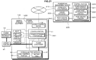
- FIG. 3A is a block diagram showing a configuration of the power/point management server 200.
- the power/point management server 200 includes a communication portion 210, a control portion 220, a power management portion 221, a point rate determination portion 222, a point issuing portion 223, an owner database 230 and a point exchanger database 240.
- the communication portion 210 functions as a reception portion and a transmission portion and is, for example, a network interface that performs communication with the energy storage equipment 100 via a network, such as the Internet, based on a specific protocol. Any type of communication method may be used, such as communication using wired communication, a wireless LAN, Wi-Fi, a 3G line and so on.
- the communication portion 210 transmits, to the power control device 10, the charge command, the discharge command and the stop command, which are issued by the power management portion 221. Additionally, the communication portion 210 transmits the command that queries the stored electricity amount information indicating the amount of the electricity stored in the storage battery module 30.
- the communication portion 210 receives the stored electricity amount information, which indicates the amount of electricity stored in the storage battery module 30 and which is transmitted from the power control device 10. Note that the transmission of the stored electricity amount information is performed in response to the query command from the point issuing portion 223 of the power/point management server 200. Further, the communication portion 210 may be connected, via the network, to a server of an electricity company in the electricity market, or to a server of a broker etc. who mediates in electricity trading on the electricity market, and the communication portion 210 may acquire information about the electricity price in the electricity market. In addition, based on the instruction of the power management portion 221, the communication portion 210 may perform communication with the server of the electricity company that is necessary to the electricity trading, such as issuing a sell order to the electricity market.
- the control portion 220 is formed, for example, of a CPU, a RAM and a ROM etc. Programs read by the CPU are stored in the ROM.
- the RAM is used as a work area of the CPU.
- the CPU executes various processing based on the programs stored in the ROM, and thus performs control of the whole power/point management server 200.
- the control portion 220 functions as the power management portion 221, the point rate determination portion 222 and the point issuing portion 223.
- the power management portion 221 uses electricity price information received by the communication portion 210 and generated electricity amount information, which indicates the amount of electricity generated by the power generation equipment 40, to determine an amount of electricity supplied to the storage battery module 30, a transmission amount to the electricity market, a transmission period, and an amount of electricity applied to home consumption in accordance with specific algorithms, and then issues the charge command, the discharge command and the stop command.
- the destination for the supply of power is specified by these various commands.
- the power supply destination is the storage battery module 30.
- the power supply destination is the power network
- the stop command is issued, the power supply destination is the power network or the electrical device.
- the issued command is transmitted by the communication portion 210 to the power control device 10. Power management processing to perform issuing and transmission of the commands will be explained in detail later.
- the point rate determination portion 222 determines a rate (hereinafter referred to as a point rate) between the points awarded to the energy storage equipment owner and the amount of electricity stored in the storage battery module 30 that is represented by the stored electricity amount data.
- a point rate a rate between the points awarded to the energy storage equipment owner and the amount of electricity stored in the storage battery module 30 that is represented by the stored electricity amount data.
- the points are awarded to the energy storage equipment owner in accordance with the amount of electricity stored in the storage battery module 30.
- Point rate information that indicates the point rate is supplied to the point issuing portion 223.
- the point issuing portion 223 issues points based on the amount of electricity stored in the storage battery module 30 that is indicated by the stored electricity amount information from the power control device 10, and on the point rate information that is supplied from the point rate determination portion 222.
- the point issuing portion 223 first issues, to the power control device 10, a command that queries the stored electricity amount information, in order to acquire the stored electricity amount information, to be used as a reference in issuing the points.
- the issued query command is transmitted to the power control device 10 by the communication portion 210.
- the points issued by the point issuing portion 223 are managed per each of the energy storage equipment owners in the owner database 230 etc. Further, point information that indicates the issued points may be transmitted to the power control device 10 via the network. Point rate determination and point management will be explained in more detail later.
- the owner database 230 stores owner information that is information relating to the energy storage equipment owner who owns the energy storage equipment 100.
- the owner information includes, for example, a name, address and telephone number of the energy storage equipment owner, and an energy storage equipment installation address. Note, however, that the owner information is not limited to the above items. Agreement may be obtained with the energy storage equipment owner with regard to the acquisition of information, and the information may include any information that can conceivably be used on the point issuer side.
- the contract information which indicates content of the contract between the point issuer and the energy storage equipment owner, is also stored in the owner database 230.
- the power management portion 221 can refer to the contract information when performing the power management processing.
- the owner information is; for example, presented in written form or the like by the energy storage equipment owner when concluding the contract between the energy storage equipment owner and the point issuer, and is then stored by being input in the owner database 230 by the point issuer. Further, when the energy storage equipment owner starts use of the power management system, an input screen may be displayed on the display portion 22 that prompts the energy storage equipment owner to input the owner information on the display portion 22 of the power control device 10. When the energy storage equipment owner performs the input using the input portion 21 in accordance with instructions on the input screen, the input owner information is transmitted to the owner database 230 via the network and is stored.
- the point exchanger database 240 stores point exchanger information, which is information relating to the point exchanger.
- the point exchanger information includes, for example, a name of the point exchanger, a company name, an organization name, address, a telephone number and contract content etc. Note, however, that the point exchanger information is not limited to the above items. Agreement may be obtained with the point exchanger with regard to the acquisition of information, and the information may include any information that can conceivably be used on the point issuer side.
- the point exchanger information is, for example, presented in written form or the like by the point exchanger when concluding the contract between the point issuer and the point exchanger, and is then stored by being input in the point exchanger database 240 by the point issuer. Further, the point exchanger information may be stored in the point exchanger database 240 by performing transmission and reception via the network. Note that, when the point issuer and the point exchanger are managed by the same corporation or organization etc., the point exchanger information and the point exchanger database 240 are not necessary.
- FIG. 3B is a block diagram showing a configuration of the point exchange server 300.
- the point exchange server 300 includes a control portion 310, a communication portion 320, an owner database 330 and a point issuer database 340.
- the control portion 310 is formed of a CPU, a RAM and a ROM etc., and executes various processing based on programs, and thus performs control of the whole point exchange server 300.
- the communication portion 320 is, for example, a network interface that performs communication with the energy storage equipment 100 via a network, such as the Internet, based on a specific protocol.
- the point exchange server 300 is connected via the network to the energy storage equipment owner.
- points, goods and services can be exchanged via the network.
- the services relating to the power management system are provided as cloud services, the points are transmitted from the point issuer to the point exchanger based on instructions of the energy storage equipment owner.
- the goods and services that can be provided via the network may be provided by the communication portion 320. Note that, as described above, the points and the goods and services may be exchanged at an actual exchange or the like.
- the owner database 330 stores owner information that is information relating to the energy storage equipment owner.
- the owner information includes, for example, a name, address, telephone number and registration number of the energy storage equipment owner, and a history of goods and services exchanges etc. Note, however, that the owner information is not limited to the above items. Agreement may be obtained with the energy storage equipment owner with regard to the acquisition of information, and the information may include any information that can conceivably be used on the point exchanger side. It should also be noted that the owner information may be shared with that stored in the owner database 230 of the power/point management server 200.
- the point issuer database 340 stores point issuer information that is information relating to the point issuer.
- the point issuer information is, for example, a name of the point issuer, a company name, an organization name, address, a telephone number and contract content etc. Note, however, that the point issuer information is not limited to the above items. Agreement may be obtained with the point issuer with regard to the acquisition of information, and the information may include any information that can conceivably be used on the point exchanger side.
- the processing by the power/point management server 200 is divided into power management processing, which instructs the charging of the storage battery module 30 by purchasing electricity or instructs the discharging of electricity from the storage battery module 30 in order to sell electricity, and point issuing processing, which issues points to the energy storage equipment owner.
- FIG. 4 is a flowchart showing a flow of the power management processing.
- step S11 information about the electricity price in the electricity market is acquired from a server of an electricity company in the electricity market or from a broker that mediates in electricity trading in the electricity market.
- step S12 stored electricity amount data that indicates the amount of electricity stored in the storage battery module 30 is acquired from the power control device 10. Note that the acquisition of the stored electricity amount data is not limited to when the power management processing is performed, and it may be constantly and regularly acquired. In this case, in the power management processing, processing is performed based on the stored electricity amount that is indicated by the latest stored electricity amount data at that point in time.
- step S13 it is determined whether or not it is appropriate to perform charging by purchasing electricity.
- the determination of whether or not the purchase of electricity is appropriate can be made, for example, by setting a predetermined threshold electricity purchase price in advance and by comparing the electricity price in the electricity market with the threshold electricity purchase price. When the electricity price in the electricity market is lower than the threshold electricity purchase price, it is determined that the purchase of electricity is appropriate. Further, the determination of whether or not the purchase of electricity is appropriate can be made, for example, using a method described hereinafter, as disclosed in Japanese Patent Application Publication No. JP-A-2002-233053 .
- time series data of the electricity price information received at the above-described step S11 is accumulated, fluctuations in the electricity price are analyzed and fluctuations over time are predicted, and an optimum electricity purchase amount and purchase timing are determined.
- a predicted value in the fluctuation of the electricity price (a reference predicted value) is calculated.
- a method to predict a future value from the past time series data is, for example, pattern analysis using a neural network.
- a fluctuation sensitivity of the electricity price may be calculated using a correlation of the electricity price when past meteorological information and external factors, such as trends in electricity demand etc., are present, and the calculated fluctuation sensitivity may be incorporated into the prediction.
- the fluctuation sensitivity with respect to that meteorological condition is 1 yen / (kWh•°C).
- the predicted value of the electricity price that takes into account meteorological conditions and external factors, such as trends in electricity demand etc. is calculated using the following Formula 1.
- Purchase electricity price predicted value reference predicted value calculated from time series data ⁇ sensitivity to meteorological conditions ⁇ sensitivity to external factors .
- the algorithm used to determine charging is not limited to the above example, and any algorithm may be used, as long as it is an algorithm that determines the purchase amount and the timing of the purchase based on price fluctuations in the electricity market, on the predicted value of the price fluctuations and on a volume of electricity that can be purchased.
- a program that is used in automatic buying and selling in another existing market, such as a stock market can be modified to suit the electricity market and used.
- step S13 When it is determined at step S13 that the purchase of electricity is appropriate (yes at step S13), the processing advances to step S14.
- step S14 the charge command that instructs charging is transmitted to the power control device 10 that is under management. Note that, along with the charging instruction, it is preferable that the charge command also includes instructions with respect to a charging period, an amount of electricity to be stored and so on.
- step S13 when it is determined at step S13 that the purchase of electricity is not appropriate (no at step S13), the processing advances to step S15. Then, it is determined at step S15 whether or not it is appropriate to sell the electricity.
- the determination of whether or not the sale of electricity is appropriate can be made, for example, by setting a predetermined threshold electricity sell price in advance and by comparing the electricity price in the electricity market with the threshold electricity sell price. When the electricity price in the electricity market is higher than the threshold electricity sell price, it is determined that the sale of electricity is appropriate. Further, the determination of whether or not the sale of electricity is appropriate can be made, for example, using a method described hereinafter, as disclosed in Japanese Patent Application Publication No. JP-A-2002-233053 .
- Prediction of the fluctuations over time of the electricity price is performed in the same manner as that described above and a predicted value of the profits obtained in the operation of the energy storage system (an electricity sales profit predicted value) is calculated.
- An expected value of a maximum value of profits up to a certain time is calculated by performing statistical processing on the above predicted value, and it is determined that the sale of electricity is appropriate when the profit calculated at a given timing is higher than the electricity sales reference profit.
- the algorithm used to determine the sale of electricity is not limited to the above example, and any algorithm may be used, as long as it is an algorithm that determines the sales amount and the timing of the sale based on price fluctuations in the electricity market, on the predicted value of the price fluctuations and on a volume of electricity that can be sold.
- a program that is used in automatic buying and selling in another existing market, such as a stock market can be modified to suit the electricity market and used.
- step S15 When it is determined at step S15 that the sale of electricity is appropriate (yes at step S15), the processing advances to step S16. At the next step S16, a sales order is issued to the electricity market. Then, after a transaction is established with the electricity market, at step S17, the discharge command is transmitted to the power control device 10. Note that, along with the discharge instruction, it is preferable that the discharge command also includes instructions with respect to a discharge period, an amount of electricity to be discharged and so on.
- step S15 determines whether the sale of electricity is not appropriate (no at step S15). If it is determined at step S15 that the sale of electricity is not appropriate (no at step S15), the processing advances to step S18.
- step S18 this means that it has been determined that the purchase of electricity is not appropriate and, further, that the sale of electricity is not appropriate.
- the stop command is transmitted to the power control device 10 in order for the energy storage equipment 100 to be in a stopped state.
- the power management processing is performed in the manner described above.
- the electricity stored in the energy storage equipment 100 is bought and sold by the power/point management server 200 determining a relationship with the electricity price in the electricity market. In this way, the point issuer can obtain a profit. Further, the energy storage equipment owner does not need to worry about the electricity price in the electricity market.
- FIG. 5 is a flowchart showing a flow of the point issuing processing.
- the point issuing processing is processing to award points to the energy storage equipment owner in accordance with the amount of electricity stored in the storage battery module 30.
- the stored electricity amount data with respect to the storage battery module 30 is acquired. Note that the acquisition of the stored electricity amount data is not limited to when the point issuing processing is performed, and it may be constantly and regularly acquired. In this case, in the point issuing processing, processing is performed based on the stored electricity amount that is indicated by the latest stored electricity amount data at that point in time.
- a point rate is determined.
- a method for determining the point rate will be explained. First, a rate with respect to a price of the goods and services provided by the goods/services provider and the points necessary to obtain those goods and services (a goods/services rate) is fixed.
- an average price of an electricity market price is determined.
- This average electricity price is a reference in the calculation of the point rate.
- the average electricity price is, for example, calculated as a unit price per unit of electricity.
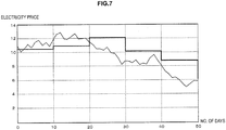
- FIG. 6 and FIG. 7 show examples of the calculation.
- FIG. 6 shows an example of calculating a moving average over 10 days, using a graph whose vertical axis is the electricity price and whose horizontal axis is a number of days.
- a fine line shows the electricity market price
- a thick line shows the moving average.
- the point rate also fluctuates, but a magnitude of the fluctuations is small compared to the fluctuations in the electricity market price.
- the point rate determination may be performed daily at midnight (zero hours) and the determined point rate may be used for the following 24 hours. Note that that determination of the point rate may be performed at a predetermined interval, such as once a week, once a month or once a year, and the determined point rate may be used until the time of the next point rate determination.
- FIG. 7 shows a case in which the average electricity price is calculated every 10 days with respect to the daily electricity market price over the past 10 days, and the calculated average electricity price is used as the reference for the point rate calculation with respect to the next 10 days.
- a fine line shows the electricity price and a thick line shows the average electricity price.
- the magnitude of the fluctuations in the point rate is small compared to the fluctuations in the electricity market price.
- the period used to calculate this average electricity price is not limited to a 10-day period and may be 1 week, 1 month or 1 year etc.
- the average electricity price calculated in the above-described manner is converted into points, based on the goods/services rate. In this way, the rate between the amount of stored electricity and the points (namely, the point rate) is determined.
- the goods/services rate is 1 point per 10 yen. Then, if it is assumed that the average electricity price over a predetermined period of the electricity market price is 10 yen per 1 kWh, the point rate is 1 point per 1 kWh. When 1 kWh of electricity is stored in the energy storage equipment 100, 1 point is awarded to the energy storage equipment owner. Note that this rate is an example for the purpose of explanation.
- the fluctuations in the point rate are small in comparison to the fluctuations in the electricity market price.
- incentives for energy storage equipment to be adopted in general households and corporations, and further, to attempt to participate in the electricity market via the system according to the present technology.
- the contract content can also be used as a reference in determining the point rate.
- the individual contract determines, for example, whether or not the charging of the storage battery module 30 is performed using only late-night electricity that is cheap in price, whether or not the electricity stored in the storage battery module 30 can be used in the home consumption by the energy storage equipment owner, and whether or not the electricity can be freely sold at the will of the owner.
- the point rate in the case of a contract in which a degree of freedom of the energy storage equipment owner is low, it is preferable for the point rate to be set high so that the energy storage equipment owner can obtain more profit.
- a case in which the degree of freedom is low is when the energy storage equipment owner cannot use the electricity stored in the storage battery module 30 for home consumption, and cannot freely buy and sell the electricity (namely, all of the stored electricity is only sold, under the management of the power/point management server 200 on the point issuer side). In this case, all of the determinations for buying and selling the electricity are performed by the power/point management server 200, and the will of the energy storage equipment owner is not taken into account, and it is thus preferable for the high point rate to be set.
- the point rate in case of a contract in which the degree of freedom of the energy storage equipment owner is high, it is preferable for the point rate to be set low so that it is advantageous to the point issuer.
- the point rate in the case of the contract in which the energy storage equipment owner can use the electricity stored in the storage battery module 30 for home consumption, a case is possible in which, even if the point issuer tries to sell the electricity, the amount of electricity stored in the storage battery module 30 is not sufficient to meet the desired amount of electricity to be sold.
- it is preferable to set the point rate such that it is advantageous to the point issuer.
- step S23 it is determined whether or not the amount of electricity stored in the storage battery module 30 has increased in comparison to the amount of stored electricity acquired a previous time.
- step S24 it is determined that the amount of stored electricity has increased.
- points are issued by the point issuing portion 223 based on the point rate determined at step S22, and the points are added. Note that the points are not added with respect to the amount of stored electricity itself, but are added with respect to the amount of increase in the amount of stored electricity from the previous time of point issuing.
- the point issuing portion 223 may also manage a history of point increases and decreases etc. Further, the point issuing portion 223 may transmit the point information to the power control device 10 via the network and the communication portion 12.
- step S23 when it is determined at step S23 that the amount of stored electricity has not increased (no at step S23), the processing advances to step S25.
- step S25 it is determined whether or not the amount of stored electricity has decreased in comparison to the amount of stored electricity acquired the previous time. When it is determined that the amount of stored electricity has not decreased (no at step S25), the processing advances to step S26.
- step S23 When it is determined at the above-described step S23 that the amount of stored electricity has not increased and it is further determined at step S25 that the amount of stored electricity has not decreased, this means that there has been no change in the amount of stored electricity. Thus, at step S26, the points are neither increased nor decreased.
- step S25 When it is determined at step S25 that the amount of stored electricity has decreased in comparison to the amount of stored electricity acquired the previous time (yes at step S25), the processing advances to step S27.
- step S27 it is determined whether or not the decrease in the amount of stored electricity is a result of the sale of electricity based on the instruction of the power/point management server 200.
- step S27 When it is determined that the decrease in the amount of stored electricity is not the result of the sale of electricity based on the instruction of the power/point management server 200 (no at step S27), the processing advances to step S28. Then, at step S28, points are subtracted by the issuing of minus points by the point issuing portion 223.
- step S28 points are subtracted by the issuing of minus points by the point issuing portion 223.
- points are subtracted.
- the points are subtracted with respect to the amount of decrease in the amount of stored electricity from the previous time of point issuing.
- step S27 when it is determined that the decrease in the amount of stored electricity is the result of the sale of electricity (yes at step S27), the processing advances to step S26 and the points are neither increased nor decreased.
- the amount of stored electricity has decreased due to the sale of electricity, this means that the point issuer has obtained a profit from the sale of the electricity, and in such a case, it is not reasonable to cause the points of the energy storage equipment owner to be decreased.
- the processing at step S27 is not necessary.
- FIG. 8 is a flowchart showing processing performed by the power control device 10. As described above, power supply control is performed by the control portion 11 in accordance with commands from the power/point management server 200.
- step S31 it is determined at step S31 whether or not a command has been received from the power/point management server 200.
- processing is not performed.
- the processing advances to step S32, and it is determined whether or not the energy storage equipment 100 is operating as a result of an instruction by the energy storage equipment owner.
- step S33 it is determined whether or not the contract between the energy storage equipment owner and the point issuer is a contract in which the instruction of the energy storage equipment owner is given priority.
- the determination of whether or not the contract is one that gives priority to the instruction of the energy storage equipment owner can be performed by referring to the contract information that indicates the contract content and that is stored in the memory 23. Alternatively, the determination can be performed by accessing the power/point management server 200 via the network and referring to the contract information stored in the owner database 230.
- the processing is ended because operation control in accordance with commands from the power/point management server 200 is not performed.
- step S34 the processing advances to step S34. Also, when it is determined at the above-described step S32 that the energy storage equipment 100 is not operating as a result of the instruction of the energy storage equipment owner (no at step S32), the processing advances to step S34.
- step S34 it is determined whether or not the command from the power/point management server 200 is the charge command.
- the processing advances to step S35 and the power conditioner 13 is caused to operate in the charge mode.
- the storage battery module 30 is charged in this manner.
- the processing advances to step S36 and it is determined whether or not the command is the discharge command.
- step S37 the power conditioner 13 is caused to operate in the discharge mode and thus electricity is discharged from the storage battery module 30.
- the sale of electricity to the electricity market is performed in this manner.
- step S38 the processing advances to step S38.
- the command is neither the charge command nor the discharge command, this means that the command is the stop command, and at step S38, the power conditioner 13 is switched to the stop mode. In the stop mode, the electricity from the power generation equipment 40 is not stored in the storage battery module 30, and is directly discharged or is allocated to home consumption. The power supply control is performed in this way, based on the commands from the power/point management server 200.
- step S32 and step S33 are not necessary.
- the points may be awarded by a method that differs from the above-described processing. This is because, in the above-described point issuing processing, the points are basically issued based on the increase and decrease in the amount of stored electricity in the storage battery module 30. Further, this is because the timing of the sale of electricity is not necessarily limited to an advantageous timing for the point issuer (a timing that differs from the timing determined to be appropriate for the sale of electricity by the power/point management server 200).
- the point rate is not set based on the average electricity price over a predetermined period, but is set based on the electricity market price at a point in time at which the electricity is sold, and the points are issued based on that point rate.
- the power supply control and issuing of points between the power control device 10 and the power/point management server 200 according to the present technology is performed in the manner described above. However, if appropriate security measures are not taken with respect to the power control device 10 and the power/point management server 200, respectively, various problems may occur. Specifically, security threats such as those described below can be assumed.
- the power control device 10 and the power/point management server 200 are connected, if it is not verified whether or not the power/point management server 200 is a valid server, there is a risk that the power control device 10 may be connected to an invalid server other than the server of the point issuer. In this case, there is a risk, for example, that a malicious third party may masquerade as the point issuer.
- various commands such as the charge command and the discharge command, are transmitted from the power/point management server 200 to the power control device 10. If the content of the command is analyzed and, further, tampered with, there is a risk that the power control device 10 and the energy storage equipment 100 may perform an operation that is not intended by the energy storage equipment owner and the point issuer. For example, in a case in which, even if the power/point management server 200 has instructed the discharge of electricity at a certain time, the electricity discharge is not performed due to tampering by a third party, it is not possible to sell an agreed amount of electricity on the electricity market.
- the stored electricity amount data etc. is transmitted to the power/point management server 200 at a timing chosen by the energy storage equipment owner, when the load on the power/point management server 200 becomes large, the system is simultaneously vulnerable to a denial of service (DoS) attack. Further, even when the power/point management server 200 transmits to the power control device 10 a command instructing the transmission of the stored electricity amount data, if the power/point management server 200 transmits the command simultaneously to many of the power control devices 10, the stored electricity amount data is transmitted at approximately the same timing and the load on the power/point management server 200 becomes large.
- DoS denial of service
- a first embodiment will be explained, which is an embodiment that addresses the problems described above in sections (1) and (2).
- the first embodiment inhibits occurrence of the problem described in section (1) above by mutual authentication between a power control device 1100 and a power/point management server 2100.
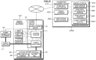
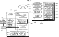
- FIG. 9 is a block diagram showing a configuration of the power control device 1100 and the power/point management server 2100 according to the first embodiment.
- the control portion 11 is formed, for example, of a CPU, a RAM and a ROM.
- the CPU executes various processing based on programs stored in the ROM, and thus performs control of the whole power control device 1100.
- the control portion 11 functions as an authentication processing portion 1101, an encryption processing portion 1102, a decryption processing portion 1103, a verification data generation portion 1104 and a verification processing portion 1105. Note that, apart from the control portion 11, the configuration is the same as that explained with reference to FIG. 2 above, and an explanation is therefore omitted here.
- the authentication processing portion 1101 is a functional portion that performs mutual authentication processing with an authentication processing portion 2101 of the power/point management server 2100.
- the mutual authentication processing performed by the authentication processing portion 1101 will be explained in detail later. If the mutual authentication is successful, it becomes possible to perform encrypted communication between the power control device 1100 and the power/point management server 2100 using confidential information that is shared in advance or shared in a process of the mutual authentication processing.
- the encryption processing portion 1102 performs encryption processing on the information, data and commands etc. transmitted from the power control device 1100 to the power/point management server 2100, using a common key encryption system, for example.
- the decryption processing portion 1103 decrypts data that is transmitted to the power control device 1100 and that has been encrypted on the power/point management server 2100 side using the common key encryption system, for example.
- the verification data generation portion 1104 generates verification data that is used to verify whether or not the information, data and commands etc. transmitted from the power control device 1100 to the power/point management server 2100 have been tampered with, and whether or not a transmission source is correct.
- the verification data is message authentication code (MAC) and the like.
- the verification processing portion 1105 verifies the verification data and thus verifies whether or not the received data has been tampered with. The verification processing will be explained in more detail later.
- the encryption processing and the verification processing using the verification data cannot be said to be completely safe unless separate keys are used for each of the processing, if authenticated encryption is used, the processing can be simultaneously executed using a single key.
- a public key cipher and a digital signature may be used in the data encryption processing and the data verification.
- the control portion 220 is formed, for example, of a CPU, a RAM and a ROM etc.
- the CPU executes various processing based on programs stored in the ROM, and thus performs control of the whole power/point management server 2100.
- the control portion 220 functions as the power management portion 221, the point rate determination portion 222, the point issuing portion 223, the authentication processing portion 2101, an encryption processing portion 2102, a decryption processing portion 2103, a verification data generation portion 2104 and a verification processing portion 2105.
- the configuration is the same as that explained with reference to FIG. 2 above, and an explanation is therefore omitted here.
- the authentication processing portion 2101 is a functional portion that performs the mutual authentication with the authentication processing portion 1101 of the power control device 1100.
- the encryption processing portion 2102 performs encryption processing on the information, data and commands etc. transmitted from the power/point management server 2100 to the power control device 1100, using the common key encryption system, for example.
- the decryption processing portion 2103 decrypts data that is transmitted to the power/point management server 2100 and that has been encrypted on the power control device 1100 side using the common key encryption system, for example.
- the verification data generation portion 2104 generates verification data that is used to verify whether or not the information, data and commands etc. transmitted from the power/point management server 2100 to the power control device 1100 have been tampered with, and whether or not a transmission source is correct.
- the verification processing portion 2105 verifies the verification data and thus verifies whether or not the received data has been tampered with, and also verifies whether or not the data has been transmitted from the valid power control device 1100.
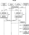
- FIG. 10 is a sequence diagram showing a flow of mutual authentication and of shared key processing using a public key cipher. Note that the mutual authentication processing is performed between the authentication processing portion 1101 of the power control device 1100 and the authentication processing portion 2101 of the power/point management server 2100, using a known challenge response system.
- the Diffie-Hellmann key exchange system is used as a shared key system.
- the power control device 1100 transmits to the power/point management server 2100 a random number Rx and a public key certificate CertX as a challenge.
- the power/point management server 2100 receives the random number Rx and the public key certificate CertX, and verifies the validity of the public key certificate CertX using public key certificates disclosed by a certificate authority (CA). For example, when the public key certificate CertX is not valid, or when a term of validity of the public key certificate CertX has expired, it is determined that the authentication has failed.
- CA certificate authority
- the power/point management server 2100 transmits a random number Ry and a public key certificate CertY to the power control device 1100.
- the power control device 1100 receives the random number Ry and the public key certificate CertY, and verifies the validity of the public key certificate CertY using the public key certificates disclosed by the certificate authority (CA).
- CA certificate authority
- a signature SigX (Ry//Wx) is generated on the power control device 1100 side using a secret key rx of the power control device 1100.
- the power control device 1100 transmits, to the power/point management server 2100, a public key Wx and the signature SigX of the power control device 1100.
- step S107 acquisition of the public key Wx and verification of the signature SigX is performed on the power/point management server 2100 side. If the verification processing of the signature SigX using the public key Wx is successful, the authentication is successful. If there is no match in the verification processing, it is determined that the authentication has failed.
- step S108 a signature SigY (Rx// Wy) is generated on the power/point management server 2100 side using a secret key ry of the server. Then, at step S109, the power/point management server 2100 transmits, to the power control device 1100, a public key Wy and the signature SigY of the power/point management server 2100.
- step S110 acquisition of the public key Wy and verification of the signature SigY is performed on the power control device 1100 side. If the verification processing of the signature SigY using the public key Wy is successful, the authentication is successful. If there is no match in the verification processing, it is determined that the authentication has failed.
- a shared key K is calculated on the power control device 1100 side using Wy and rx. Meanwhile, at step S112, the shared key K is calculated on the power/point management server 2100 side using Wx and ry. Then, as shown at step S113, encrypted communication using the shared key encryption system becomes possible between the power control device 1100 and the power/point management server 2100.
- the mutual authentication and shared key processing for encryption are performed between the power control device 1100 and the power/point management server 2100 in the manner described above.
- Examples of the shared key encryption system include the Triple Data Encryption Standard (Triple DES), the Advanced Encryption Standard (AES) and CLEFIA (Sony Corporation trademark) etc.
- Triple DES Triple Data Encryption Standard
- AES Advanced Encryption Standard
- CLEFIA Synchrony Corporation trademark
- the method to perform mutual authentication and shared key processing for encryption between the power control device 1100 and the power/point management server 2100 is not limited to the above-described examples, and any method may be adopted as long as mutual authentication can be performed.
- the power control device 1100 and the power/point management server 2100 use the verification data to perform tampering verification on the various pieces of information, data and commands etc. that are transmitted and received, and to verify a transmission source.
- the verification data is, for example, a MAC.
- the MAC is a message authentication code that is used to verify that transmitted data has not been tampered with, using the shared key encryption system.
- FIG. 11 is a sequence diagram showing a flow of the verification processing using a MAC as the verification data. Note that in FIG. 11 shows verification processing for data that is transmitted from the power/point management server 2100 to the power control device 1100.
- the verification data generation portion 2104 of the power/point management server 2100 calculates a MAC based on the data to be transmitted to the power control device 1100.
- the transmission data with the MAC added is transmitted to the power control device 1100.
- step S123 based on the transmission data transmitted from the power/point management server 2100, the verification processing portion 1105 of the power control device 1100 calculates a MAC using the same method as that used by the verification data generation portion 2104 of the power/point management server 2100.
- step S124 verification is performed by comparing the MAC calculated at step S121 with the MAC calculated at step S123. If the MACs match each other, it can be confirmed that the transmission data has not been tampered with. On the other hand, if the MACs do not match each other, this means that the transmission data has been tampered with.
- a method for calculating the MAC is not particularly limited and a known method can be used, such as CMAC using a common key block cipher or HMAC using a keyed hash function, for example.
- a digital signature based on a public key cipher can also be used as the verification data.
- FIG. 12A is a sequence diagram showing processing when the above-described verification processing is applied to transmission and reception of the stored electricity amount information that indicates the amount of electricity stored in the storage battery module 30. Note that it is assumed that the transmission of the stored electricity amount information is performed in response to the query command from the power/point management server 2100 to the power control device 1100. The query command transmitted to the power control device 1100 in the above-described manner is issued by the point issuing portion 223.
- the power/point management server 2100 transmits, to the power control device 1100, the command that queries the stored electricity amount information.
- the control portion 11 of the power control device 1100 transmits a query to the cell control portion 32 of the storage battery module 30 to query the amount of stored electricity.
- the cell control portion 32 supplies the stored electricity amount information to the control portion 11, the stored electricity amount information indicating the amount of electricity stored in the storage battery module 30 at the time of the query.
- the verification data generation portion 1104 of the control portion 11 generates a MAC, as the verification data, based on the stored electricity amount information. Then, at step S135, the stored electricity amount information to which the MAC is added is transmitted to the power/point management server 2100 via the communication portion 12.
- the verification processing portion 2105 of the power/point management server 2100 uses the MAC transmitted from the power control device 1100 to verify whether or not the stored electricity amount information has been tampered with, and to verify whether or not it has been transmitted from a valid transmission source. As described above, the verification is performed by the verification processing portion 2105 of the power/point management server 2100 also generating a MAC from the stored electricity amount data in the same manner as the power control device 1100, and then comparing the generated MAC with the transmitted MAC.
- the point issuing processing in accordance with the amount of stored electricity is performed by the point issuing portion 223.
- the point issuing processing is performed by the point issuing portion 223.
- the MACs do not match each other, this means that the stored electricity amount information has been tampered with or the stored electricity amount data has been transmitted from an invalid transmission source, and the point issuing is not performed.
- the verification processing is performed with respect to the information transmitted and received between the power control device 1100 and the power/point management server 2100, utilizing the MAC, digital signature and the like as the verification data. In this way, it is possible to inhibit the fraudulent acquisition of points by manipulating the amount of stored electricity.
- FIG. 12B is a sequence diagram showing processing when encryption processing is applied to the transmission and reception of the stored electricity amount information. Step S131 to step S136 in FIG. 12B are the same as those shown in FIG. 12A .
- the encryption processing portion 1102 encrypts the stored electricity amount information. Then, at step S135, the stored electricity amount data that has been encrypted and to which the verification data has also been added is transmitted to the power/point management server 2100.
- step S138 the stored electricity amount data is decrypted by the decryption processing portion 2103 of the power/point management server 2100.
- both the encryption processing and the tampering verification processing are applied to the information, but it is not necessary to use both the series of processing, and the encryption processing only may be applied. However, from the point of view of security, it is preferable for both the encryption processing and the tampering verification processing to be applied.
- the various commands such as the charge command, the discharge command etc., issued by the power management portion 221 of the power/point management server 2100 are transmitted to the power control device 1100. If the content of these commands is analyzed and, further, tampered with, there is a risk that operation not intended by the energy storage equipment owner and the point issuer may be performed by a third party.
- FIG 13A is a sequence diagram showing processing when the above-described tampering verification processing is applied to the transmission and reception of the commands between the power/point management server 2100 and the power control device 1100.
- the explanation is made taking as an example a case in which the discharge command is transmitted to the power control device 1100 from the power/point management server 2100.
- the tampering verification processing can be applied to the various commands that are transmitted and received between the power/point management server 2100 and the power control device 1100.
- the verification data generation portion 2104 of the power/point management server 2100 generates, for example, a MAC or a digital signature as the verification data.
- the discharge command with the verification data added is transmitted to the power control device 1100 via the communication portion 210.
- the verification processing portion 1105 of the power control device 1100 uses the verification data to perform the tampering verification processing, and thus verifies whether or not the discharge command from the power/point management server 2100 has been tampered with and whether or not the discharge command has been transmitted from the valid power/point management server 2100.
- the control portion 11 controls the power conditioner 13 such that the electricity is discharged from the storage battery module 30.
- the discharge of electricity is not performed.
- FIG. 13B is a sequence diagram showing processing when the encryption processing is applied to the transmission and reception of the commands. Note that step S141 to step S144 in FIG. 13B are the same as those of FIG. 13A .
- the encryption processing portion 1102 of the power/point management server 2100 encrypts the discharge command that is to be transmitted from the power/point management server 2100 to the power control device 1100. Then, the discharge command that has been encrypted and to which the verification data has also been added is transmitted to the power control device 1100 via the communication portion 210.
- the verification processing portion 1105 of the power control device 1100 verifies whether or not the discharge command has been tampered with. As a result of the verification, if it is determined that the discharge command has not been tampered with, the control portion 11 controls the power conditioner 13 such that the electricity is discharged from the storage battery module 30. On the other hand, when it is determined that the discharge command has been tampered with, the discharge of electricity is not performed. Then, at step S146, the decryption processing portion 1103 of the power control device 1100 decrypts the discharge command.
- FIG. 14 is a block diagram showing a configuration of the power control device 10 and of a power/point management server 2200 according to the second embodiment.
- An equipment ID database 2201 is a database that stores and holds equipment identification (ID) that identifies the power control device 10 that is under the management of the power/point management server 2200.
- the equipment ID database 2201 may store the equipment ID in association with the owner information stored in the owner database 230. Note that, in FIG. 14 , the equipment ID database 2201 is denoted by a block that is separate to the owner database 230, but a single mass storage medium may serve as both the owner database 230 and the equipment ID database 2201.
- the equipment ID is an ID that is assigned to each of the power control devices 10 and that can identify the power control device 10.
- the equipment ID corresponds to identification information corresponding to a power control device within the scope of the appended claims.
- the equipment ID is assigned to the power control device 10 in advance, such as at the time of manufacture, and is stored, for example, in the ROM of the control portion 11 of the power control device 10.
- the control portion 220 executes various processing based on programs, and thus performs control of the whole power/point management server 2200. Further, by executing predetermined programs, the control portion 220 also functions as the power management portion 221, the point rate determination portion 222, the point issuing portion 223 and an equipment ID management portion 2202. Note that, apart from the equipment ID management portion 2202, the configuration is the same as that explained with reference to FIG. 2 above, and an explanation is therefore omitted here.
- the equipment ID management portion 2202 manages the equipment IDs that are stored in the equipment ID database 2201.
- the equipment ID management portion 2202 performs processing in order to register the equipment ID of each of the power control devices 10 in the equipment ID database 2201, or to delete the equipment ID, and thus manages a plurality of the power control devices 10, 10 ... 10, as shown in FIG. 15 .
- the power/point management server 2200 receives the equipment ID from the power control device 10 that is newly connected.
- the equipment ID may be transmitted to the power/point management server 2200 at the point in time at which the power control device 10 is connected to the power/point management server 2200.
- the equipment ID management portion 2202 determines whether or not the connected power control device 10 is the new device. The determination can be made, for example, by referring to the equipment ID database 2201 and, if the equipment ID received at step S211 is not in the equipment ID database 2201, it can be determined that it is the new power control device 10.
- step S212 if it is not the new power control device 10 (no at step S212), as the equipment ID is already registered in the equipment ID database 2201, the registration processing is not necessary and the processing ends. On the other hand, if the new power control device 10 is connected to the power/point management server 2200 (yes at step S212), the processing advances to step S213.
- the equipment ID management portion 2202 registers the received equipment ID in the equipment ID database 2201.
- deletion processing to delete the equipment ID of the power control device 10 will be explained with reference to a flowchart shown in FIG. 17 .
- the deletion of the equipment ID is performed when a failure occurs in the power control device 10 and the power control device 10 is inoperable, or when the power control device 10 is disposed of.
- step S221 it is determined whether or not the connection between the power control device 10 and the power/point management server 2200 has been disconnected. For example, when the stored electricity amount data is not transmitted from the power control device 10 for a specific period of time, it can be determined that the connection has been disconnected. Further, when the connection is disconnected, the power control device 10 may transmit a predetermined signal to the power/point management server 2200 to notify the disconnection, and it may be determined that the connection has been disconnected when the power/point management server 2200 receives the predetermined signal.
- the energy storage equipment owner may be allowed to instruct the connection to be cut and the equipment ID to be deleted from the equipment ID database 2201, by performing a predetermined operation input on the input portion 21.
- step S222 the equipment ID corresponding to the disconnected power control device 10 is deleted from the equipment ID database 2201.
- the equipment ID may be deleted after a predetermined period of time has elapsed after it is determined that the connection between the power control device 10 and the power/point management server 2200 has been disconnected. In this way, it is possible to inhibit the equipment ID from being mistakenly deleted.
- the point issuing portion 223 acquires the stored electricity amount information that indicates the amount of electricity stored in the storage battery module 30, and issues the points based on the stored electricity amount information.
- the point issuing portion 223 notifies the equipment ID management portion 2202 of this fact.
- the equipment ID management portion 2202 may delete the equipment ID as an indication that the energy storage equipment owner no longer uses the service of the power management system.
- the power/point management server 2200 stores and manages the equipment ID of each of the power control devices 10 under its management on the equipment ID database 2201. Further, the equipment ID of the power control device 10 that has been disposed of etc. is deleted. In this way, it is possible to always ascertain the number of the power control devices 10 that are under the management of the power/point management server 2200.
- FIG. 18 is a block diagram showing the configuration of the energy storage equipment 100 and a configuration of a power/point management server 2300 according to the third embodiment.
- the control portion 11 of a power control device 1300 functions as a clock portion 1301 and as a transmission data generation portion 1302. Note that, apart from the clock portion 1301 and the transmission data generation portion 1302, the configuration is the same as that explained with reference to FIG. 2 above, and an explanation is therefore omitted here.
- the clock portion 1301 measures a current time and generates time information.
- the clock portion 1301 corresponds to an identifier generation portion within the scope of the appended claims.
- the transmission data generation portion 1302 generates the stored electricity amount data to be transmitted to the power/point management server 2300.
- the transmission data generation portion 1302 generates the stored electricity amount data by adding a predetermined identifier to the stored electricity amount information that indicates the amount of electricity stored in the storage battery module 30.
- the stored electricity amount information included in the stored electricity amount data is a reference for the point issuing by the power/point management server 2300, as described above.
- the generation and transmission of the stored electricity amount data is performed in response to the command from the point issuing portion 223 of the power/point management server 2300 querying the amount of stored electricity.
- FIG. 19A and FIG. 19B show examples of the stored electricity amount data generated by the transmission data generation portion 1302.
- Stored electricity amount data 1350 shown in FIG. 19A is formed of a header 1351, time information 1352 that is an identifier, and stored electricity amount information 1353.
- the time information 1352 is acquired from the clock portion 1301 and indicates, for example, a date and time at which the command querying the amount of stored electricity is received from the power/point management server 2300.
- the transmission data generation portion 1302 When the transmission data generation portion 1302 acquires the time information and the stored electricity amount information, the transmission data generation portion 1302 generates the stored electricity amount data by adding the header and the time information to the stored electricity amount information.
- the generated stored electricity amount data is transmitted to the power/point management server 2300 via the communication portion 12 and the network.
- the power/point management server 2300 will be explained.
- the control portion 220 of the power/point management server 2300 also functions as a clock portion 2301 and an identifier verification portion 2302. Note that, apart from the clock portion 2301 and the identifier verification portion 2302, the configuration is the same as that explained with reference to FIG. 2 above, and an explanation is therefore omitted here.
- the clock portion 2301 measures a current time and generates time information. Note that, the clock portion 2301 of the power/point management server 2300 and the clock portion 1301 of the power control device 1300 are synchronized, and a time indicated by the generated time information is substantially the same. As a method for synchronization, for example, a method is conceivable in which the time information generated by the clock portion 2301 of the power/point management server 2300 is transmitted to the power control device 1300 and the power control device 1300 sets the clock portion 1301 based on that time information.
- the identifier verification portion 2302 verifies whether or not the stored electricity amount data transmitted from the power control device 1300 is valid. As described above, the generation and the transmission of the stored electricity amount data is performed in response to the query command from the power/point management server 2300. Thus, it is possible to determine whether or not the stored electricity amount data is valid based on the time indicated by the time information included in the stored electricity amount data, and on the time at which the power/point management server 2300 transmits the query command to the power control device 1300.
- the stored electricity amount data is valid. This is because, when the times are substantially the same or are within the predetermined close range, it can be said that the stored electricity amount data is generated in response to the query command from the power/point management server 2300.
- the stored electricity amount data is not valid, namely that it has not been generated in response to the latest query command.
- Verification results from the identifier verification portion 2302 are supplied to the point issuing portion 223. Then, when the supplied verification result indicates that the stored electricity amount data is valid, the point issuing portion 223 issues points in accordance with the stored electricity amount information. On the other hand, when the verification result indicates that the stored electricity amount data is not valid, the point issuing portion 223 does not issue the points.
- the power/point management server 2300 transmits, to the power control device 1300, the command that queries the stored electricity amount data.
- the query command is issued by the point issuing portion 223.
- the identifier verification portion 2302 acquires, from the clock portion 1301, time information that indicates a time of transmission of the query command.
- the transmission data generation portion 1302 of the power control device 1300 acquires, from the clock portion 1301, time information that indicates a time at which the query command is received from the power/point management server 2300. Then, the query is performed with respect to the amount of electricity stored in the storage battery module 30. In response to the query, at step S305, the storage battery module 30 transmits the stored electricity amount information to the control portion 11.
- the transmission data generation portion 1302 generates the stored electricity amount data that is formed of the stored electricity amount information, the time information (the identifier) acquired at step S303 and the header. Then, at step S307, the control portion 11 transmits the stored electricity amount data to the power/point management server 2300 via the communication portion 12.
- the identifier verification portion 2302 of the power/point management server 2300 compares the time information acquired at step S302 with the time information included in the stored electricity amount data, and thus verifies whether or not the stored electricity amount data is valid.
- the time information on the power/point management server 2300 side and the time information on the power control device 1300 side are within the predetermined close range, it is determined that the stored electricity amount data is valid, namely, that the stored electricity amount data has been generated in response to the latest query command.
- the point issuing portion 223 issues the points based on the stored electricity amount information included in the stored electricity amount data.
- the time information on the power/point management server 2300 side and the time information on the power control device 1300 side are not within the predetermined close range, it is determined that the stored electricity amount data is not valid, namely, that the stored electricity amount data has not been generated in response to the latest query command. In this case, the point issuing is not performed.
- the identifier is not limited to the time information, and a packet sequence number may be used as the identifier as shown in FIG. 19B .
- the identifier verification portion 2302 can determine whether or not the stored electricity amount data is valid by checking the sequence number.
- any information may be used as the identifier, as long as the information is unique to the transmitted stored electricity amount data and is information that differs for each time of generation and time of transmission.
- FIG. 21 is a block diagram showing the configuration of the energy storage equipment 100 and the configuration of the power/point management server 200 according to the fourth embodiment.
- the control portion 11 of a power control device 1400 functions as a power determination portion 1401. Apart from the power determination portion 1401, the configuration is the same as that explained with reference to FIG. 2 above, and an explanation is therefore omitted here.
- the power determination portion 1401 determines whether or not the stored electricity amount information acquired from the storage battery module 30 and information acquired from the power conditioner 13 satisfy predetermined conditions. The information acquired from the power conditioner 13 and determination processing performed by the power determination portion 1401 will be explained in detail later. A determination result by the power determination portion 1401 is transmitted to the power/point management server 200 via the communication portion 12 and the network.
- FIG. 22 is a sequence diagram of the power determination processing.
- the query command is transmitted from the power/point management server 200 that instructs the power control device 1400 to transmit the stored electricity amount information.
- the power determination portion 1401 transmits, to the cell control portion 32 of the storage battery module 30, a query command that requests transmission of the information to be used in the power determination processing.
- the power determination portion 1401 also transmits, to the power conditioner 13, a query command that requests transmission of the information to be used in the power determination processing.
- the cell control portion 32 of the storage battery module 30 transmits, to the power determination portion 1401, the requested information (hereinafter referred to as first determination information) to be used in the power determination processing.
- first determination information supplied from the storage battery module 30.
- the cell control portion 32 of the storage battery module 30 receives the query command from the power determination portion 1401, it measures an amount of stored electricity E1 in the storage battery module 30 at that point in time. Then, a difference is calculated between the amount of stored electricity E1 and an amount of stored electricity E0 that was previously measured when the power determination portion 1401 sent a previous query command (namely, E0 - E1 is calculated).
- the cell control portion 32 transmits the amount of stored electricity difference (E0 - E1) to the power determination portion 1401 as the first determination information.
- the power conditioner 13 transmits, to the power determination portion 1401, the requested information (hereinafter referred to as second determination information) to be used in the power determination processing.
- the second determination information transmitted from the power conditioner 13 will be explained.
- the power conditioner 13 constantly acquires a supply power amount P (t) of the power supplied to the storage battery module 30. A time at which the query command from the power determination portion 1401 is received is set to t0, and a time at which a previous query command is received from the power determination portion 1401 is set to 0. Then, an integral value P' of P (t) that is calculated using the following Formula 6 is transmitted to the power determination portion 1401 as the second determination information.
- P ′ ⁇ O tO P t dt
- the power determination portion 1401 estimates an amount of self-discharge of the storage battery module 30 as ⁇ , and determines whether or not the following Formula 7 is satisfied.
- Formula 7 below is satisfied, the power determination portion 1401 determines that the amount of electricity stored in the storage battery module 30 and the supply power amount from the power conditioner 13 to the storage battery module 30 match each other.
- Formula 7 below is not satisfied, the power determination portion 1401 determines that amount of electricity stored in the storage battery module 30 and the supply power amount from the power conditioner 13 to the storage battery module 30 do not match each other.
- the determination that the amount of electricity stored in the storage battery module 30 and the supply power amount of the power conditioner 13 match each other is not limited to when Formula 7 is fully satisfied, and a range in which they are determined to match each other may have a predetermined width, taking into account a tolerance etc.
- E 0 ⁇ E 1 + ⁇ P ′
- the control portion 11 transmits the power determination result and the stored electricity amount information to the power/point management server 200 via the communication portion 12.
- the point issuing portion 223 of the power/point management server 200 performs the point issuing processing based on the stored electricity amount information.
- the point issuing processing is performed when the power determination portion 1401 determines that the amount of electricity stored in the storage battery module 30 and the supply power amount of the power conditioner 13 match each other, and if they do not match, the point issuing processing is not performed.
- the power/point management server 200 may notify the power control device 1400 of that fact.
- the notification is presented to the energy storage equipment owner by being displayed as an image on the display portion 22 of the energy storage equipment 100, for example.
- the cell control portion 32 of the storage battery module 30 calculates "E0 - El" and the power conditioner 13 calculates a value of Formula 6, but the power determination portion 1401 may perform calculation of each of the values.
- FIG. 23 is a block diagram showing a configuration of a power/point management server 2400 and the power control device 1400 according to the first modified example of the fourth embodiment.
- the control portion 220 of the power/point management server 2400 functions as a power determination portion 2401.
- the configuration is the same as that explained with reference to FIG. 2 above, and an explanation is therefore omitted here.
- FIG. 24 is a sequence diagram of the power determination processing according to the first modified example of the fourth embodiment.
- the control portion 220 of the power/point management server 2400 functions as the power determination portion 2401, and the power determination processing is performed on the power/point management server 2400 side.
- step S401 to step S405 shown in the sequence in FIG. 24 are the same as those of the fourth embodiment and an explanation is therefore omitted here.
- the control portion 11 of the power control device 1400 transmits the first determination information, the second determination information and the stored electricity amount information to the power/point management server 2400 via the communication portion 12. Then, in the power/point management server 2400, the first determination information and the second determination information is supplied to the power determination portion 2401, and the stored electricity amount data is supplied to the point issuing portion 223.
- the power determination portion 2401 of the power/point management server 2400 performs the power determination processing. Note that the power determination processing is the same as that of the fourth embodiment and an explanation is therefore omitted here. The determination result by the power determination processing is supplied to the point issuing portion 223.
- the point issuing portion 223 performs the point issuing processing based on the stored electricity amount information.
- the point issuing processing is performed when it is determined by the power determination portion 2401 that the first determination information and the second determination information satisfy the above-described Formula 7. On the other hand, when the first determination information and the second determination information do not satisfy the above-described Formula 7, the point issuing processing is not performed.
- the power determination processing according to the first modified example of the fourth embodiment is performed in the above-described manner. In this way, the power determination processing may also be performed on the power/point management server 2400 side.
- FIG. 25 is a block diagram showing the configuration of the second modified example of the fourth embodiment.
- the control portion 11 of the power control device 1400 functions as an authentication processing portion 1402.
- the authentication processing portion 1402 is the same as the above-described authentication processing portion 1101 according to the first embodiment, and performs the mutual authentication with an authentication processing portion 2401 of the power/point management server 2400, using the challenge response system, for example.
- the power conditioner 13 is provided with an encryption processing portion 1403 and a verification data generation portion 1404.
- the storage battery module 30 is provided with an encryption processing portion 1405 and a verification data generation portion 1406.
- the power conditioner 13, and the encryption processing portion and the verification data generation portion of the storage battery module 30 may be realized by a CPU executing programs, or may be realized by dedicated hardware.
- the functions of the encryption processing portion 1403 in the power conditioner 13 are the same as those according to the above-described first embodiment, and the encryption processing portion 1403 performs encryption processing on the second determination information using the common key encryption system, for example. Further, the functions of the verification data generation portion 1404 are the same as those according to the above-described first embodiment, and the verification data generation portion 1404 generates verification data that is used to verify whether or not the second determination information supplied from the power conditioner 13 to the control portion 11 has been tampered with.
- the verification data may be a MAC, a digital signature or the like.
- the functions of the encryption processing portion 1405 of the storage battery module 30 are the same as those according to the above-described first embodiment, and the encryption processing portion 1405 performs encryption processing on the first determination information using the common key encryption system, for example. Further, the functions of the verification data generation portion 1406 are the same as those according to the above-described first embodiment, and the verification data generation portion 1406 generates verification data that is used to verify whether or not the first determination information supplied from the storage battery module 30 to the control portion 11 has been tampered with.
- the verification data may be a MAC, a digital signature or the like.
- the control portion 220 of the power/point management server 2400 functions as the authentication processing portion 2401, a decryption processing portion 2402, a verification processing portion 2403 and a power determination portion 2404.
- the authentication processing portion 2401 is the same as the above-described authentication processing portion 2101 according to the first embodiment, and performs the mutual authentication with the authentication processing portion 1402 of the power control device 1400 using the challenge response system, for example.
- the decryption processing portion 2402 uses a common key to decrypt the information encrypted by the power conditioner 13 and the storage battery module 30 using the common key encryption system, for example.
- the verification processing portion 2403 verifies whether or not the information transmitted to the power/point management server 2400 from the power control device 1400 has been tampered with.
- FIG. 26 is a sequence diagram of power determination processing according to the second modified example of the fourth embodiment. Note that, step S401 to step S403 shown in the sequence in FIG. 26 are the same as those shown in FIG. 22 .
- the encryption processing portion 1405 performs encryption processing on the first determination information. Further, at step S422, the verification data generation portion 1406 generates verification data based on the first determination information. Then, at step S423, the verification data is added to the encrypted first determination information and the resultant first determination information is transmitted to the control portion 11.
- the encryption processing portion 1403 performs encryption processing on the second determination information. Further, at step S425, the verification data generation portion 1404 generates verification data based on the second determination information. Then, at step S426, the verification data is added to the encrypted second determination information and the resultant second determination information is transmitted to the control portion 11.
- control portion 11 transmits the first determination information and the second determination information to the power/point management server 2400 via the communication portion 12.
- the verification processing portion 2403 verifies whether or not the first determination information and the second determination information have been tampered with, and whether or not the first determination information and the second determination information have been transmitted from the valid transmission source.
- the encryption processing portion 2402 decrypts the encrypted first determination information and second determination information.
- the power determination portion 2404 performs the power determination processing of the first determination information and the second determination information.
- FIG. 27 is a block diagram showing the configuration of the energy storage equipment 100 and of the power/point management server 200 according to the fifth embodiment.
- the control portion 11 of a power control device 1500 functions as a power determination portion 1501. Apart from the power determination portion 1501, the configuration is the same as that explained with reference to FIG. 2 above, and an explanation is therefore omitted here.
- First discharge amount information which indicates an amount of electricity discharged to a power sales meter 130 from the power conditioner 13, is supplied to the power determination portion 1501 from the power conditioner 13. Further, second discharge amount information, which indicates an amount of electricity discharged to the power network via the power sales meter 130, is supplied to the power determination portion 1501 from the power sales meter 130. Then, the power determination portion 1501 determines whether or not the first discharge amount information and the second discharge amount information match each other, or determines whether or not the first discharge amount information and the second discharge amount information are approximate values within a predetermined range. A determination result by the power determination portion 1501 is transmitted to the power/point management server 200 via the communication portion 12 and the network.
- the power management portion 221 of the power/point management server 200 transmits, to the power control device 1500, the discharge command that instructs the discharge of the instructed amount of electricity to be discharged.
- the control portion 11 of the power control device 1500 controls the power conditioner 13 such that the electricity is discharged to the power sales meter 130.
- the power conditioner 13 discharges the electricity stored in the storage battery module 30, and outputs the electricity to the power sales meter 130.
- step S504 the power conditioner 13 transmits the first discharge amount information to the control portion 11. Further, when the discharge of electricity to the system power 140 is complete, at step S505, the power sales meter 130 transmits the second discharge amount information to the control portion 11.
- the power determination portion 1501 determines whether or not the first discharge amount information and the second discharge amount information match each other, or whether or not the first discharge amount information and the second discharge amount information are approximate values within the predetermined range. In this way, it is possible to determine whether or not the discharge of electricity has been accurately performed. When the first discharge amount information and the second discharge amount information match each other or are approximate values within the predetermined range, it can be determined that the discharge of electricity has been accurately performed. On the other hand, when the first discharge amount information and the second discharge amount information do not match each other or are not approximate values within the predetermined range, it can be determined that the discharge of electricity has not been accurately performed.
- the predetermined range of approximate values may be set in advance, taking into account error etc. arising from characteristics of the power conditioner 13, power loss on power paths and so on.
- step S507 the control portion 11 of the power control device 1500 transmits determination result information to the power/point management server 200 via the communication portion 12.
- the point issuer can ascertain whether or not the discharge of electricity has been correctly performed.
- the power/point management server 200 may transmit, to the power control device 1500, a predetermined control signal that causes the display portion 22 to display that fact, thereby notifying the energy storage equipment owner of that fact.
- a message may be displayed on the display portion 22 that prompts the energy storage equipment owner to check whether or not a fault or an abnormality has occurred in the power control device 1500 or the energy storage equipment 100.
- the determination result by the power determination portion 1501 is stored in the owner database 230 etc. in association with the information of each of the energy storage equipment owners, and this may be used as material to determine a fault or dishonest behavior etc.
- FIG. 29 is a block diagram showing a configuration of the modified example of the fifth embodiment.
- the control portion 11 of the power control device 1500 functions as an authentication processing portion 1502.
- the authentication processing portion 1502 is the same as the above-described authentication processing portion 1101 according to the first embodiment, and performs the mutual authentication with an authentication processing portion 2501 of a power/point management server 2500 using the challenge response system, for example.
- the power conditioner 13 is provided with an encryption processing portion 1503 and a verification data generation portion 1504. Further, the power sales meter 130 is provided with an encryption processing portion 131 and a verification data generation portion 132.
- the power conditioner 13, and the encryption processing portion and the verification data generation portion of the power sales meter 130 may be realized by a CPU executing programs, or may be realized by dedicated hardware.
- the functions of the encryption processing portion 1503 in the power conditioner 13 are the same as those according to the above-described first embodiment, and the encryption processing portion 1503 performs encryption processing on the first discharge amount information using the common key encryption system, for example. Further, the functions of the verification data generation portion 1504 are the same as those according to the above-described first embodiment, and the verification data generation portion 1504 generates verification data that is used to verify whether or not the first discharge amount information supplied from the power conditioner 13 to the control portion 11 has been tampered with.
- the verification data may be a MAC, a digital signature or the like.
- the functions of the encryption processing portion 131 of the power sales meter 130 are the same as those according to the above-described first embodiment, and the encryption processing portion 131 performs encryption processing on the second discharge amount information using the common key encryption system, for example. Further, the functions of the verification data generation portion 132 are the same as those according to the above-described first embodiment, and the verification data generation portion 132 generates verification data that is used to verify whether or not the second discharge amount information supplied from the power sales meter 130 to the control portion 11 has been tampered with.
- the verification data may be a MAC, a digital signature or the like.
- the control portion 220 of the power/point management server 2500 functions as an authentication processing portion 2501, a decryption processing portion 2502, a verification processing portion 2503 and a power determination portion 2504.
- the authentication processing portion 2501 is the same as the authentication processing portion 2101 of the above-described first embodiment, and performs the mutual authentication with the authentication processing portion 1502 of the power control device 1500 using the challenge response system, for example.
- the decryption processing portion 2502 uses a common key to decrypt the first discharge amount information that has been encrypted by the power conditioner 13 using the common key encryption system, for example, and to decrypt the second discharge amount information that has been encrypted by the power sales meter 130 using the common key encryption system, for example.
- the verification processing portion 2503 verifies whether or not the first discharge amount information and the second discharge amount information transmitted to the power/point management server 2500 from the power control device 1500 has been tampered with.
- step S501 to step S503 are the same as those of the fifth embodiment and an explanation is therefore omitted here.
- the encryption processing portion 1503 of the power conditioner 13 performs encryption processing on the first discharge amount information at step S511.
- the verification data generation portion 1504 of the power conditioner 13 generates verification data with respect to the first discharge amount information.
- the power conditioner 13 transmits the encrypted first discharge amount information and the verification data to the control portion 11 of the power control device 1500.
- the encryption processing portion 131 of the power sales meter 130 performs encryption processing on the second discharge amount information at step S514.
- the verification data generation portion 132 of the power sales meter 130 generates verification data with respect to the second discharge amount information.
- the power sales meter 130 transmits the encrypted second discharge amount information and the verification data to the control portion 11 of the power control device 1500.
- control portion 11 transmits the first discharge amount information and its verification data, and the second discharge amount information and its verification data to the power/point management server 2500.
- the verification processing portion 2503 verifies whether or not the first discharge amount information and the second discharge amount information have been tampered with, based on their respective verification data. Then, at step S519, the decryption processing portion 2502 of the power/point management server 2500 decrypts the encrypted first discharge amount information and second discharge amount information.
- the power determination portion 2504 performs determination processing of the first discharge amount information and the second discharge amount information. In this way, it is possible to determine whether or not the discharge of electricity has been performed accurately.
- the first discharge amount information and the second discharge amount information match each other or are approximate values within a predetermined range, it can be determined that the discharge of electricity has been accurately performed.
- the first discharge amount information and the second discharge amount information do not match each other or are not approximate values within the predetermined range, it can be determined that the discharge of electricity has not been accurately performed.
- the power determination processing may be performed on the power/point management server 2500 side. Further, by performing the encryption processing and the tampering verification processing on the first discharge amount information and the second discharge amount information, it is possible to enhance security of the power management system.
- FIG. 31 is a block diagram showing the configuration of the energy storage equipment 100 and a configuration of a power/point management server 2600 according to the sixth embodiment.
- the control portion 220 of the power/point management server 2600 of the sixth embodiment additionally functions as a query control portion 2601.
- the query control portion 2601 Based on a predetermined query schedule, the query control portion 2601 transmits a predetermined control signal to the point issuing portion 223 and thus controls issue of the command querying the stored electricity amount information performed by the point issuing portion 223. More specifically, the issue of the query command by the point issuing portion 223 is performed based on the control of the query control portion 2601.
- the query control portion 2601 ascertains positions of the power control device 10 etc. Then, as shown in FIG. 32 , based on the installation addresses etc. of the power control devices 10 etc., the power control devices 10 etc. are divided into a plurality of groups. In FIG. 32 , the power control devices 10 etc. are divided into 3 groups, namely group A to group C. Then, the issue of the command that queries the stored electricity amount information is controlled such that the point issuing portion 223 issues the command per group in the order of group A, group B and then group C, for example.
- the number of power control devices 10 etc. included in a single group may be determined by performing load estimation based on the processing capability of the power/point management server 2600, and by setting the number such that the load does not exceed a predetermined level that is set in advance.
- the query command that queries the amount of stored electricity is not transmitted simultaneously to all the power control devices 10 that are under the management of the power/point management server 2600, and are transmitted in a dispersed manner.
- a great quantity of the stored electricity amount information is not transmitted to the power/point management server 2600 at a single time.
- the query control portion 2601 may constantly monitor the load on the power/point management server 2600, and when the load becomes equal to or greater than the predetermined level, the query control portion 2601 may stop the query command, for example.
- control may be performed when the power management portion 221 issues the various commands, such as the charge command, the discharge command and the stop command etc.
- FIG. 33 is a block diagram showing the configuration of the energy storage equipment 100 according to the seventh embodiment.
- the control portion 11 of a power control device 1700 functions as an authentication processing portion 1701, an encryption processing portion 1702, a decryption processing portion 1703, a verification data generation portion 1704 and a verification processing portion1705.
- the power conditioner 13 is provided with an authentication processing portion 1711, an encryption processing portion 1712, a decryption processing portion 1713, a verification data generation portion 1714 and a verification processing portion 1715.
- the storage battery module 30 is provided with an authentication processing portion 1721, an encryption processing portion 1722, a decryption processing portion 1723, a verification data generation portion 1724 and a verification processing portion 1725.
- the power generation equipment 40 is also provided with an authentication processing portion 43, an encryption processing portion 44, a decryption processing portion 45, a verification data generation portion 46 and a verification processing portion 47.
- the power sales meter 130 is provided with an authentication processing portion 133, an encryption processing portion 134, a decryption processing portion 135, a verification data generation portion 136 and a verification processing portion 137.
- each portion may be realized by a CPU executing programs, or may be realized by dedicated hardware.
- the mutual authentication is respectively performed between the control portion 11 and the power conditioner 13, between the control portion 11 and the storage battery module 30, between the control portion 11 and the power generation equipment 40 and between the control portion 11 and the power sales meter 130.
- the method of the mutual authentication is the same method as that described in the first embodiment above.
- the encryption processing and the tampering verification processing are also performed with respect to the data transmitted and received, respectively, between the control portion 11 and the power conditioner 13, the control portion 11 and the storage battery module 30, the control portion 11 and the power generation equipment 40 and the control portion 11 and the power sales meter 130.
- the encryption processing and the tampering verification processing are performed on the supply power amount (the amount of power supplied to the storage battery module 30) transmitted from the power conditioner 13 to the control portion11, on the stored electricity amount information that is supplied from the storage battery module 30 to the control portion11, on the generated electricity amount information that is supplied from the power generation equipment 40 to the control portion 11 and on the discharge amount information that is supplied from the power sales meter 130 to the control portion11.
- the processing is not limited to that described above, and the encryption processing and the tampering verification processing may be performed on all of the various data and commands that are transmitted and received.
- results indicating the success or failure of the mutual authentication between the control portion 11 and each of the other portions may be transmitted to the power/point management server and the status of each thus managed.
- FIG. 34 is a block diagram showing the configuration of the energy storage equipment 100 and a configuration of a power/point management server 2800 according to the eighth embodiment.
- the power/point management server 2800 is provided with a software database 2801. Further, by executing predetermined programs, the control portion 220 functions as a software supply portion 2802 and a verification data generation portion 2803. The control portion 11 of a power control device 1800 functions as a verification processing portion 1801.
- the software database 2801 stores various types of software that are used in the power control device 1800, the energy storage equipment 100 and the power generation equipment 40.
- update data for the stored software is also stored.
- the software and the update data stored in the software database 2801 are supplied to the software database 2801 from a server of an external software development company or the like via the network, and are then stored in the software database 2801. Further, the software and the update data may also be uploaded to the software database 2801 by the point issuer.
- the software supply portion 2802 supplies the software that is stored in the software database 2801. In accordance with a request from the power control device 1800, for example, the software supply portion 2802 selects a relevant software from among the software stored in the software database 2801. Further, the software may be supplied to the power control device 1800 based on an instruction input by the point issuer.
- the software may be supplied to the power control device 1800 in accordance with a predetermined algorithm. For example, even if there is no request from the power control device 1800 that is the newly connected power control device 1800, the necessary software is supplied.
- the software supply portion 2802 supplies the update data to the power control device 1800.
- the verification data generation portion 2803 has the same functions as those described in the first embodiment etc., and generates verification data that is used to perform tampering verification with respect to the software and the update data that is supplied by the software supply portion 2802. The generated verification data is added to the software and the update data and is transmitted to the power control device 1800.
- the control portion 11 of the power control device 1800 functions as the verification processing portion 1801.
- the verification processing portion 1801 has the same functions as those described in the first embodiment etc., and performs tampering verification processing based on the verification data that is added to the software or the update data. For example, when the verification data is a digital signature, the verification processing portion 1801 performs the verification processing using a public key of an originator.
- the control portion 11 of the power control device 1800 installs and uses the software supplied from the power/point management server 2800. Further, an update is performed using the update data. Then, when the software is to be used on portions other than the control portion 11, such as the power conditioner 13 and the power generation equipment 40 etc., the software or the update data is supplied to each of the portions via the control portion 11.
- the software used on the power control device 1800 and the energy storage equipment 100 etc. is limited to the valid software only, and it is thus possible to inhibit the problem described in section (8) above, namely, to inhibit analysis etc. of the power control device 1800 and the energy storage equipment 100 etc.
- FIG. 35 is a block diagram showing the configuration of the power control device 10 and a configuration of a power/point management server 2900 according to the ninth embodiment.
- the power/point management server 2900 has a user authentication table 2901, and further, the control portion 220 of the power/point management server 2900 functions as a user authentication portion 2902.
- user authentication is performed, for example, when the energy storage equipment owner performs a setting operation to set a service utilization method for the services by the power management system. If authentication is not performed when performing the setting operation to set the service utilization method, there is a risk that a third party may make settings that are not intended by the energy storage equipment owner.
- the user authentication is not limited to when the setting operation to set the service utilization method is performed, and the user authentication may be always performed when the energy storage equipment owner performs any kind of operation with respect to the power control device 10.
- the user authentication table 2901 is formed of a recording medium and stores user IDs set by users in association with passwords, as shown in FIG. 36 . These pieces of information are set when use of the services by the power management system according to the present technology is started, and are stored in the user authentication table 2901. Further, the information may be stored in association with the equipment ID of the power control device 10 that is owned by the energy storage equipment owner.
- the user authentication portion 2902 performs authentication processing of the energy storage equipment owner that uses the energy storage equipment 100 etc.
- the user authentication portion 2902 refers to the user authentication table 2901 and performs user authentication by determining whether or not an associated relationship between the user ID and the password input by the energy storage equipment owner is a match.
- the associated relationship between the input user ID and the password matches that in the user authentication table 2901, it is determined that the person that has input the user ID and the password is the valid energy storage equipment owner.
- the associated relationship between the input user ID and password does not match that in the user authentication table 2901, it is determined that the person that has input the user ID and the password is not the valid energy storage equipment owner.
- FIG. 37 is a sequence diagram showing a flow of user authentication processing.
- the energy storage equipment owner accesses the power control device 10.
- the power control device 10 is accessed, for example, by the energy storage equipment owner using the input portion 21 to perform a predetermined input operation.
- the control portion 11 displays a user ID and password input screen on the display portion 22, such as that shown in FIG. 38A .
- the energy storage equipment owner uses the input portion 21 to input the user ID and the password.
- step S904 the control portion 11 transmits the input user ID and password to the power/point management server 2900 via the communication portion 12. Then, the user ID and the password are supplied to the user authentication portion 2902. Note that, when the control portion 11 of the power control device 10 transmits the user ID and the password to the power/point management server 2900 via the communication portion 12, the control portion 11 may cause the display portion 22 to display a display screen, such as the one shown in FIG. 38B , that indicates to the energy storage equipment owner that the authentication is being performed.
- the user authentication portion 2902 determines whether or not a combination of the supplied user ID and password matches that in the user authentication table 2901. Then, at step S906, the user authentication portion 2902 transmits to the power control device 10 data that indicates an authentication result.
- the user authentication portion 2902 determines that the combination of the user ID and the password matches that in the user authentication table 2901, the user authentication portion 2902 transmits data indicating that the valid energy storage equipment owner has been authenticated to the power control device 10. Then, by performing predetermined image display control, the control portion 11 of the power control device 10 displays a service utilization method setting screen on the display portion 22, such as the one shown in FIG. 38C .
- the user authentication portion 2902 transmits data indicating that the valid energy storage equipment owner cannot be authenticated to the power control device 10. Then, by performing predetermined display control, the control portion 11 causes the display portion 22 to display a screen, such as the one shown in FIG. 38D , that prompts the energy storage equipment owner to once more input the user ID and the password.
- the images shown in FIG. 38A to FIG. 38D are examples only and the images displayed on the display portion 22 are not limited to those examples.
- the user authentication processing is performed using the password in this way.
- the user authentication is not limited to using the password.
- biometric authentication may be adopted, using a fingerprint, a voice print, vein patterns, a retina and the like. Note that, when using the biometric authentication, it is necessary for the power control device 10 to be provided with sensors, cameras etc. to acquire information used in the authentication of the fingerprint etc.
- the user authentication processing is preferable for the user authentication processing to be performed apart from when setting the service utilization method.
- the user authentication processing may also be performed when the energy storage equipment owner uses the terminal device 50 to access the power control device 10 from outside, as described above with reference to FIG. 2 . In this way, it is possible to inhibit fraudulent access by a third party other than the energy storage equipment owner.
- a user ID and password input screen such as the one shown in FIG. 38A , is displayed on a display portion of the terminal device 50. Then, authentication processing is performed similarly to the above-described authentication processing. Access is only allowed when it is verified that the energy storage equipment owner is valid. In this way, it is possible for the energy storage equipment owner to verify a stored electricity status, a discharge status etc., and to set the operation mode and so on when away from home.
- the electricity market is limited to bulk trading, and it is not possible to participate in the electricity market, for example, with the amount of electricity that is stored in this type of the small-scale energy storage equipment 100 that is installed in a general household.
- a trading unit on the Japan Electric Power Exchange is 1000 kW of electric power and 30 minutes of time. Therefore, a minimum amount of power that can be traded is 500 kWh.
- a storage capacity of household storage batteries is a maximum of around several tens of kWh, and output is around several kW at most.
- it is difficult for general households to individually participate in the electricity market even if the use of power generation equipment and energy storage equipment increases in general households etc. This is one factor preventing participation in the electricity market.
- the point issuer who has the power/point management server 200 it is preferable for the point issuer who has the power/point management server 200 to have under its management a plurality of the energy storage equipment owners who own the power generation equipment 40 and the energy storage equipment 100. Then, the electricity trading between the plurality of the energy storage equipment 100 and the electricity market is performed under the management of the power/point management server 200.
- an electricity trading volume is larger, and it is as if bulk trading is being performed.
- bulk trading under advantageous conditions is made possible by bundling together a plurality of the energy storage equipment owners.
- the energy storage equipment owner owns the energy storage equipment 100, but the electricity supply control of the energy storage equipment 100 is performed based on management instructions of the power/point management server 200. Then, the power/point management server 200 performs the sale and purchase of electricity based on the electricity price in the electricity market. In addition, the energy storage equipment owner is issued with points in accordance with the amount of stored electricity. Thus, the energy storage equipment owner can obtain a profit through points in accordance with the amount of stored electricity, without concern for the electricity price in the electricity market and without taking on any price fluctuation risk. In this way, as it is possible to suppress the price fluctuation risk of the electricity price with respect to the energy storage equipment owner, the adoption of power generation equipment and energy storage equipment throughout society can be encouraged.
- the point issuer can raise profits by selling the electricity at an appropriate timing and at an appropriate price. Therefore, by using the system according to the present technology, the point issuer can cover system operation costs.
- the goods/services provider that provides the goods and services can also obtain large profits.
- products and services that take into account the environment are relatively high in price compared to normal products and services. It is thought that customers who have a high environmental awareness will be the customers who purchase these relatively high-priced products and services.
- the energy storage equipment owner participating in the system according to the present technology is highly environment-conscious, if a company that wishes to sell environment-friendly products and services becomes the goods/services provider, an increase in sales can be expected. Further, even if it is the company that does not handle environment-friendly products and services, participation in the system according to the present technology is, in itself, a contribution to environmental activities, and thus the company can promote itself to society as being environmentally conscious.
- the present technology achieves various effects, such as those described above, and as it is possible to confer profits on each party participating in the system according to the present technology, it is possible to encourage the adoption of energy storage equipment.
- the present technology can also take the following configurations.
Landscapes
- Engineering & Computer Science (AREA)
- Power Engineering (AREA)
- Computer Security & Cryptography (AREA)
- Computer Hardware Design (AREA)
- Computing Systems (AREA)
- General Engineering & Computer Science (AREA)
- Computer Networks & Wireless Communication (AREA)
- Signal Processing (AREA)
- Physics & Mathematics (AREA)
- Electromagnetism (AREA)
- General Physics & Mathematics (AREA)
- Radar, Positioning & Navigation (AREA)
- Automation & Control Theory (AREA)
- Supply And Distribution Of Alternating Current (AREA)
- Management, Administration, Business Operations System, And Electronic Commerce (AREA)
- Charge And Discharge Circuits For Batteries Or The Like (AREA)
Claims (15)
- Leistungssteuervorrichtung (1300), die zusammen mit einer Speicherbatterie (30) eine Energiespeicherausrüstung (100) bildet, die Leistungssteuervorrichtung umfassend:einen Empfangsabschnitt (12), der Anweisungen von einer Leistungsverwaltungsvorrichtung (2300) empfängt, die Laden und Entladen der Speicherbatterie verwaltet;einen Leistungskonditionierer (13), der einer im Voraus bestimmten Bestimmung Elektrizität zur Zuführung zuführt;einen Steuerabschnitt (11), der Betrieb des Leistungskonditionierers basierend auf den Anweisungen von der Leistungsverwaltungsvorrichtung steuert;und gekennzeichnet durcheinen Kennungserzeugungsabschnitt (1301), der Zeitinformationen durch Messen von Zeit erzeugt, wobei die Zeitinformationen einen Zeitpunkt angeben, zu dem eine Abfrage der Informationen über die gespeicherte Elektrizitätsmenge von der Leistungsverwaltungsvorrichtung empfangen wird; undeinen Übertragungsabschnitt (12), der Informationen über die gespeicherte Elektrizitätsmenge, die eine Menge gespeicherter Elektrizität in der Speicherbatterie angeben, und die Zeitinformationen an die Leistungsverwaltungsvorrichtung überträgt.
- Leistungsverwaltungsvorrichtung (2300), umfassend:einen Empfangsabschnitt (210), der Informationen über die gespeicherte Elektrizitätsmenge, die eine Menge gespeicherter Elektrizität in einer Speicherbatterie (30) angeben, und Zeitinformationen empfängt, wobei die Informationen über die gespeicherte Elektrizitätsmenge und die Zeitinformationen von einer Leistungssteuervorrichtung (1300), die zusammen mit der Speicherbatterie (30) eine Energiespeicherausrüstung bildet, übertragen werden;wobei die Zeitinformationen einen Zeitpunkt angeben, zu dem eine Abfrage der Informationen über die gespeicherte Elektrizitätsmenge durch die Leistungssteuervorrichtung (1300) empfangen wird;einen Punktausgabeabschnitt (223), der eine Abfrage hinsichtlich der Leistungssteuervorrichtung (1300) der Informationen über die gespeicherte Elektrizitätsmenge, die die Menge gespeicherter Elektrizität in der Speicherbatterie (30) angeben, durchführt und Punkte hinsichtlich der Energiespeicherausrüstung gemäß der durch die Informationen über die gespeicherte Elektrizitätsmenge angegebene Menge gespeicherter Elektrizität ausgibt;und gekennzeichnet durcheinen Taktabschnitt (2301), der eine aufgezeichnete Zeit erzeugt, wenn der Punktausgabeabschnitt die Abfrage durchführt; undeinen Kennungsverifizierungsabschnitt (2302), der eine Gültigkeit der Informationen über die gespeicherte Elektrizitätsmenge durch Vergleichen der aufgezeichneten Zeit mit den Zeitinformationen verifiziert.
- Leistungssteuervorrichtung (1300) nach Anspruch 1, ferner umfassend:einen Authentifizierungsverarbeitungsabschnitt (1402), der Authentifizierungsverarbeitung mit der Leistungsverwaltungsvorrichtung durchführt.
- Leistungssteuervorrichtung (1300) nach Anspruch 1, ferner umfassend:mindestens eines eines Verschlüsselungsverarbeitungsabschnitts (1402) und eines Verifizierungsdaten-Erzeugungsabschnitts (1404), wobei, wenn Authentifizierung durch den Authentifizierungsverarbeitungsabschnitt erfolgreich ist, der Verschlüsselungsverarbeitungsabschnitt Kommunikation mit der Leistungsverwaltungsvorrichtung (2300) verarbeitet und der Verifizierungsdaten-Erzeugungsabschnitt Verifizierungsdaten erzeugt, die verwendet werden, zu verifizieren, ob der Inhalt der Kommunikation mit der Leistungsverwaltungsvorrichtung manipuliert wurde,wobei der Kommunikationsabschnitt (12) die Verifizierungsdaten an die Leistungsverwaltungsvorrichtung überträgt.
- Leistungsverwaltungsvorrichtung (2300) nach Anspruch 1, ferner umfassend:eine Kennungsinformationen-Datenbank (230), die Kennungsinformationen korrespondierend mit der Leistungssteuervorrichtung speichert.
- Leistungssteuervorrichtung (1300) nach Anspruch 1, ferner umfassend:einen Leistungsbestimmungsabschnitt (1501), der bestimmt, ob eine Menge gespeicherter Elektrizität in der Speicherbatterie und eine Zuführungsleistungsmenge von dem Leistungskonditionierer zu der Speicherbatterie im Voraus bestimmte Bedingungen erfüllt, wobeider Übertragungsabschnitt (12) Informationen über die gespeicherte Elektrizitätsmenge, die die Menge gespeicherter Elektrizität in der Speicherbatterie angeben, und Bestimmungsergebnisinformationen, die ein Bestimmungsergebnis durch den Leistungsbestimmungsabschnitt angeben, an die Leistungsverwaltungsvorrichtung überträgt.
- Leistungsverwaltungsvorrichtung (2300) nach Anspruch 2, wobei
der Empfangsabschnitt (210) Informationen über die gespeicherte Elektrizitätsmenge und Bestimmungsergebnisinformationen, übertragen von einer Leistungssteuervorrichtung, wobei die Leistungssteuervorrichtung eine Energiespeicherausrüstung mit der Speicherbatterie bildet, empfängt und die Leistungssteuervorrichtung enthält:einen Empfangsabschnitt (12), der Anweisungen von der Leistungsverwaltungsvorrichtung, die Laden und Entladen der Speicherbatterie verwaltet, empfängt,einen Leistungskonditionierer (13), der einer im Voraus bestimmten Bestimmung Elektrizität zur Zuführung zuführt.einen Steuerabschnitt (11), der Betrieb des Leistungskonditionierers basierend auf den Anweisungen von der Leistungsverwaltungsvorrichtung steuert;einen Leistungsbestimmungsabschnitt (1501), der bestimmt, ob eine Menge gespeicherter Elektrizität in der Speicherbatterie und eine Zuführungsleistungsmenge von dem Leistungskonditionierer zu der Speicherbatterie im Voraus bestimmte Bedingungen erfüllt, undeinen Übertragungsabschnitt (12), der Informationen über die gespeicherte Elektrizitätsmenge, die eine Menge gespeicherter Elektrizität in der Speicherbatterie angeben, und die Bestimmungsergebnisinformationen, die ein Bestimmungsergebnis durch den Leistungsbestimmungsabschnitt angeben, an die Leistungsverwaltungsvorrichtung überträgt; undwobei der Punktausgabeabschnitt (223) Punkte hinsichtlich jeder der Energiespeicherausrüstung gemäß der durch die Informationen über die gespeicherte Elektrizitätsmenge angegebene Menge gespeicherter Elektrizität ausgibt, wenn die Bestimmungsergebnisinformationen die im Voraus bestimmten Bedingungen erfüllen. - Leistungsverwaltungsvorrichtung (2300) nach Anspruch 7, ferner umfassend:mindestens eines eines Entschlüsselungsverarbeitungsabschnitts (1403) und eines Verifizierungsverarbeitungsabschnitts (1404), wobei der Entschlüsselungsverarbeitungsabschnitt die Informationen über die gespeicherte Elektrizitätsmenge und die Bestimmungsergebnisinformationen, die verschlüsselt und übertragen werden, entschlüsselt und der Verifizierungsverarbeitungsabschnitt basierend auf Verifizierungsdaten, die zusammen mit den Informationen über die gespeicherte Elektrizitätsmenge und den Bestimmungsergebnisinformationen übertragen werden, verifiziert, ob die Informationen über die gespeicherte Elektrizitätsmenge und die Bestimmungsergebnisinformationen manipuliert wurden.
- Leistungssteuervorrichtung (1300) nach Anspruch 1, wobei:der Leistungskonditionierer (13) mit einem Entladungsmeter verbunden ist und der Elektrizität einer im Voraus bestimmt Bestimmung für Zuführung zuführt, wobei der Entladungsmeter eine Menge der Entladung zu einem Leistungsnetzwerk misst; undeinen Leistungsbestimmungsabschnitt (1501), der bestimmt, ob eine von dem Leistungskonditionierer zu dem Entladungsmeter ausgegebene Menge von Elektrizität und die Menge von Elektrizität, die zu dem Leistungsnetzwerk über den Entladungsmeter ausgegeben werden, im Voraus bestimmte Bedingungen erfüllen.
- Leistungsverwaltungsvorrichtung (2300) nach Anspruch 2, wobei:der Empfangsabschnitt (210), der Informationen über die gespeicherte Elektrizitätsmenge empfängt, übertragen von einer Vielzahl von Leistungssteuervorrichtungen, die jeweils zusammen mit der Speicherbatterie eine Energiespeicherausrüstung bilden;der Punktausgabeabschnitt (223), der eine Abfrage hinsichtlich der Vielzahl von Leistungssteuervorrichtungen von Informationen über die gespeicherte Elektrizitätsmenge durchführt und Punkte hinsichtlich jeder der Leistungssteuervorrichtungen gemäß der durch die Informationen über die gespeicherte Elektrizitätsmenge angegebenen Menge gespeicherter Elektrizität, empfangen durch den Empfangsabschnitt, ausgibt; undein Abfragesteuerabschnitt (2601) die Abfrage durch den Punktausgabeabschnitt der Informationen über die gespeicherte Elektrizitätsmenge steuert.
- Leistungsverwaltungsvorrichtung (2300) nach Anspruch 10, wobei
der Abfragesteuerabschnitt (2601) die Vielzahl von Leistungssteuervorrichtungen in eine Vielzahl von Gruppen aufteilt und die Abfrage durch den Punktausgabeabschnitt der Informationen über die gespeicherte Elektrizitätsmenge derart steuert, dass die Abfrage der Informationen über die gespeicherte Elektrizitätsmenge für jede der Gruppen durchgeführt wird. - Leistungsverwaltungsvorrichtung (2300) nach Anspruch 2, ferner umfassend:eine Software-Datenbank (2801), die Software speichert;einen Verifizierungsdaten-Erzeugungsabschnitt (2803), der Manipulationsverifizierungsdaten erzeugt, die verwendet werden, zu verifizieren, ob der Leistungssteuervorrichtung zugeführte Software aus der in der Software-Datenbank gespeicherten Software manipuliert wurde; undeinen Software-Zuführungsabschnitt (2902), der die Manipulationsverifizierungsdaten und die in der Software-Datenbank gespeicherte Software der Leistungssteuervorrichtung zuführt.
- Leistungssteuervorrichtung (1300) nach Anspruch 1, ferner umfassend:einen Eingabeabschnitt (21), der eine Eingabe von Authentifizierungsinformationen von einem Benutzer empfängt; undeinen Übertragungsabschnitt (12), der die Authentifizierungsinformationen an die Leistungsverwaltungsvorrichtung überträgt.
- Leistungsverwaltungsvorrichtung (2300) nach Anspruch 2, ferner umfassend:einen Kommunikationsabschnitt (210), der Informationen über die gespeicherte Elektrizitätsmenge und Authentifizierungsinformationen, die von einer Leistungssteuervorrichtung, die zusammen mit einer Speicherbatterie eine Energiespeicherausrüstung bildet, übertragen werden, empfängt, wobei die Informationen über die gespeicherte Elektrizitätsmenge eine Menge gespeicherter Elektrizität in der Speicherbatterie angeben und die Authentifizierungsinformationen durch einen Benutzer an der Leistungssteuervorrichtung eingegeben werden; undeinen Benutzerauthentifizierungsabschnitt (2902), der Authentifizierung des Benutzers basierend auf den Authentifizierungsinformationen durchführt.
- Leistungsverwaltungssystem, umfassend:die Leistungssteuervorrichtung nach Anspruch 1; unddie Leistungsverwaltungsvorrichtung nach Anspruch 2.
Applications Claiming Priority (1)
| Application Number | Priority Date | Filing Date | Title |
|---|---|---|---|
| JP2011125379A JP2012252580A (ja) | 2011-06-03 | 2011-06-03 | 電力制御装置、電力管理装置および電力管理システム |
Publications (3)
| Publication Number | Publication Date |
|---|---|
| EP2530802A2 EP2530802A2 (de) | 2012-12-05 |
| EP2530802A3 EP2530802A3 (de) | 2016-01-20 |
| EP2530802B1 true EP2530802B1 (de) | 2018-12-19 |
Family
ID=46201413
Family Applications (1)
| Application Number | Title | Priority Date | Filing Date |
|---|---|---|---|
| EP12169183.6A Not-in-force EP2530802B1 (de) | 2011-06-03 | 2012-05-24 | Leistungsteuervorrichtung, Leistungsverwaltungsvorrichtung und Leistungsverwaltungssystem |
Country Status (4)
| Country | Link |
|---|---|
| US (2) | US9343905B2 (de) |
| EP (1) | EP2530802B1 (de) |
| JP (1) | JP2012252580A (de) |
| CN (1) | CN102810874B (de) |
Families Citing this family (48)
| Publication number | Priority date | Publication date | Assignee | Title |
|---|---|---|---|---|
| US9318917B2 (en) * | 2009-04-09 | 2016-04-19 | Sony Corporation | Electric storage apparatus and power control system |
| JP5510019B2 (ja) * | 2010-04-16 | 2014-06-04 | 富士通株式会社 | 電力制御方法、プログラム及び装置 |
| JP5874311B2 (ja) * | 2011-10-24 | 2016-03-02 | ソニー株式会社 | 電力需要予測装置、電力需要予測方法および電力需要予測システム |
| JP2013165448A (ja) | 2012-02-13 | 2013-08-22 | Sony Corp | 機器管理装置及び機器管理方法 |
| US9461471B2 (en) * | 2012-06-20 | 2016-10-04 | Causam Energy, Inc | System and methods for actively managing electric power over an electric power grid and providing revenue grade date usable for settlement |
| US9098817B2 (en) * | 2012-07-11 | 2015-08-04 | Nec Laboratories America, Inc. | Method for real-time control of energy storage units to reduce electricity cost |
| US9270118B2 (en) | 2012-07-19 | 2016-02-23 | Solarcity Corporation | Techniques for controlling energy generation and storage systems |
| US9831677B2 (en) * | 2012-07-19 | 2017-11-28 | Solarcity Corporation | Software abstraction layer for energy generation and storage systems |
| CN104854770B (zh) * | 2012-12-21 | 2018-10-12 | 索尼公司 | 供电控制设备、电池设备、供电系统以及供电控制方法 |
| JP5805690B2 (ja) * | 2013-03-21 | 2015-11-04 | 三菱電機株式会社 | エネルギーマネジメントシステム、及び、エネルギー管理方法 |
| KR101524345B1 (ko) * | 2013-03-26 | 2015-06-04 | (주)제이에이치에너지 | 절전형 다기능 야외 조명 장치 |
| US20150021999A1 (en) * | 2013-07-19 | 2015-01-22 | John A. Rodriguez | Grid apportioning bimodal power module and method |
| US10432753B2 (en) | 2013-08-16 | 2019-10-01 | Fujitsu Limited | Demand response event dissemination system and method |
| JP6233694B2 (ja) * | 2013-09-27 | 2017-11-22 | パナソニックIpマネジメント株式会社 | エネルギー管理システム及び方法 |
| JP6245610B2 (ja) * | 2014-03-28 | 2017-12-13 | シーシーエス株式会社 | 照明制御電源 |
| WO2015151278A1 (ja) * | 2014-04-04 | 2015-10-08 | 株式会社日立製作所 | 電力取引計画立案支援システム及び電力取引計画立案支援方法 |
| JP6297466B2 (ja) * | 2014-10-22 | 2018-03-20 | 株式会社日立製作所 | 卸電力価格予測システムおよび卸電力価格予測方法 |
| CN107580738A (zh) * | 2014-12-31 | 2018-01-12 | 仰融 | 储存与资本化离峰电的系统和方法 |
| KR101950445B1 (ko) * | 2015-01-19 | 2019-02-20 | 엘에스산전 주식회사 | 태양광 발전 시스템 |
| JP6420457B2 (ja) * | 2015-02-25 | 2018-11-07 | 京セラ株式会社 | 電力変換装置、分電盤及び運転切替方法 |
| JP6523074B2 (ja) * | 2015-06-30 | 2019-05-29 | 株式会社東芝 | 蓄電池管理システム |
| US20170205865A1 (en) * | 2016-01-20 | 2017-07-20 | Electronics And Telecommunications Research Institute | Method and apparatus for energy storage virtualization |
| EP3439140B1 (de) * | 2016-03-29 | 2020-09-23 | Kyocera Corporation | Verwaltungssystem, verwaltungsverfahren, leistungsumwandlungsvorrichtung und verwaltungsvorrichtung |
| JP6745638B2 (ja) * | 2016-04-28 | 2020-08-26 | 三菱電機株式会社 | 電力制御システム |
| JP6701965B2 (ja) * | 2016-05-27 | 2020-05-27 | 日本電気株式会社 | 処理装置、処理方法及びプログラム |
| US20200076198A1 (en) * | 2017-03-03 | 2020-03-05 | General Electric Company | Microgrid energy reservoir transaction verification via secure, distributed ledger |
| CN110419151B (zh) * | 2017-03-13 | 2022-11-15 | 松下知识产权经营株式会社 | 电力控制装置和电力系统 |
| KR101906046B1 (ko) * | 2017-04-07 | 2018-10-08 | 인천대학교 산학협력단 | 상품 구매 전략 및 공정 운영 전략을 수립하는 방법 및 이를 수행하는 의사 결정 컴퓨팅 시스템 |
| CN107239874B (zh) * | 2017-04-26 | 2023-05-16 | 广西电网有限责任公司电力科学研究院 | 一种面向轨道交通的电能质量及节能分析系统 |
| JP2019164643A (ja) | 2018-03-20 | 2019-09-26 | 本田技研工業株式会社 | 情報提供装置、情報提供方法及びシステム |
| JP2019165584A (ja) * | 2018-03-20 | 2019-09-26 | 本田技研工業株式会社 | 情報提供装置、情報提供方法及びシステム |
| EP3843228B1 (de) * | 2018-08-24 | 2024-07-24 | Kyocera Corporation | Stromverwaltungssystem und stromverwaltungsverfahren |
| CN109376970B (zh) * | 2018-12-21 | 2021-03-12 | 青岛理工大学 | 适用于能源互联网的动态实时电价机制形成方法及系统 |
| CN109473998B (zh) * | 2018-12-21 | 2021-07-02 | 华中科技大学 | 一种应用于风电场出力平滑的储能配置方法 |
| JP7243425B2 (ja) * | 2019-05-14 | 2023-03-22 | トヨタ自動車株式会社 | 電池情報管理システムおよび電池情報管理方法 |
| JP7403251B2 (ja) * | 2019-07-12 | 2023-12-22 | 株式会社エナリス | 電力資産運用システム及び方法 |
| JP7225051B2 (ja) * | 2019-07-30 | 2023-02-20 | シャープ株式会社 | 制御装置、蓄電池制御システムおよび制御装置の制御方法 |
| CN110533311B (zh) * | 2019-08-21 | 2022-07-15 | 三峡大学 | 基于能源路由器的智能社区协调调度系统及方法 |
| CN110852483B (zh) * | 2019-10-15 | 2022-05-20 | 同济大学 | 一种城轨交通地面储能选址方法、系统及装置 |
| CN110968892A (zh) * | 2019-11-18 | 2020-04-07 | 广东卓维网络有限公司 | 一种基于电量数据查询的数据加密系统 |
| CN112865073B (zh) * | 2021-01-11 | 2023-01-03 | 南方电网科学研究院有限责任公司 | 功率速降故障的安全稳定控制系统切机方法、装置及设备 |
| JP7468459B2 (ja) | 2021-06-07 | 2024-04-16 | トヨタ自動車株式会社 | 制御システム |
| JP7591738B2 (ja) | 2021-06-23 | 2024-11-29 | パナソニックIpマネジメント株式会社 | 装置、情報処理モジュール、及び、情報処理方法 |
| CN113947822A (zh) * | 2021-10-18 | 2022-01-18 | 襄阳市雄狮光电科技有限公司 | 一种视角可调式行车记录仪日夜共焦镜头 |
| CN114383230B (zh) * | 2021-12-20 | 2024-03-22 | 青岛海尔空调器有限总公司 | 蓄能空调系统的控制方法、控制系统、电子设备和介质 |
| CN116488283A (zh) * | 2023-03-25 | 2023-07-25 | 东莞市斐石智联科技有限公司 | 一种储能电源充电类型识别及计量系统以及方法 |
| US12395339B2 (en) * | 2023-05-18 | 2025-08-19 | Cisco Technology, Inc. | Fast repowering using cryptographically protected identity |
| KR102865460B1 (ko) * | 2023-11-13 | 2025-09-29 | 주식회사 이프 | Ess 통합 제어 플랫폼 시스템 |
Family Cites Families (37)
| Publication number | Priority date | Publication date | Assignee | Title |
|---|---|---|---|---|
| US6389010B1 (en) * | 1995-10-05 | 2002-05-14 | Intermec Ip Corp. | Hierarchical data collection network supporting packetized voice communications among wireless terminals and telephones |
| US10135253B2 (en) * | 2000-12-29 | 2018-11-20 | Abb Schweiz Ag | System, method and computer program product for enhancing commercial value of electrical power produced from a renewable energy power production facility |
| JP2002233053A (ja) | 2001-02-05 | 2002-08-16 | Hitachi Ltd | 蓄電システム及び方法 |
| JP4538203B2 (ja) * | 2003-06-09 | 2010-09-08 | トヨタ自動車株式会社 | エネルギー管理装置 |
| JP4945077B2 (ja) * | 2004-12-03 | 2012-06-06 | シャープ株式会社 | 蓄電設備管理システム |
| JP5379948B2 (ja) * | 2005-02-02 | 2013-12-25 | シャープ株式会社 | 分散型発電管理システム用のサーバーおよびそれを用いた発電管理システム |
| US7739513B2 (en) * | 2005-02-22 | 2010-06-15 | Sony Corporation | Secure device authentication |
| WO2006138592A2 (en) * | 2005-06-17 | 2006-12-28 | Optimal Licensing Corporation | Fast acting distributed power system for trasmission and distribution system load using energy storage units |
| JP5064003B2 (ja) * | 2005-12-20 | 2012-10-31 | パナソニック株式会社 | 認証システム、及び認証装置 |
| US20070282495A1 (en) * | 2006-05-11 | 2007-12-06 | University Of Delaware | System and method for assessing vehicle to grid (v2g) integration |
| JP4270236B2 (ja) * | 2006-07-31 | 2009-05-27 | トヨタ自動車株式会社 | 電力システムおよび交流電力供給方法 |
| JP4967608B2 (ja) * | 2006-11-07 | 2012-07-04 | 株式会社明電舎 | 分散電源システム |
| JP4969229B2 (ja) * | 2006-12-18 | 2012-07-04 | 三菱重工業株式会社 | 電力貯蔵装置及びハイブリッド型分散電源システム |
| JP4949902B2 (ja) * | 2007-03-16 | 2012-06-13 | 日本碍子株式会社 | 二次電池の電力制御方法 |
| US7715951B2 (en) * | 2007-08-28 | 2010-05-11 | Consert, Inc. | System and method for managing consumption of power supplied by an electric utility |
| JP2009251895A (ja) * | 2008-04-04 | 2009-10-29 | Sony Corp | 電力交換装置、電力交換方法、プログラム、および電力交換システム |
| CN102067408A (zh) * | 2008-06-27 | 2011-05-18 | 夏普株式会社 | 向电力需求设施分配电力的电力控制系统 |
| EP2389617A4 (de) * | 2009-01-26 | 2015-02-25 | Geneva Cleantech Inc | Energieverbrauchüberwachung mit einer fernanzeige und automatische erkennung eines geräts mit grafischer benutzerschnittstelle |
| US9318917B2 (en) * | 2009-04-09 | 2016-04-19 | Sony Corporation | Electric storage apparatus and power control system |
| JP5434229B2 (ja) * | 2009-04-22 | 2014-03-05 | 株式会社デンソー | 充電制御装置 |
| JP5412364B2 (ja) * | 2009-07-16 | 2014-02-12 | 株式会社日立製作所 | 情報処理方法および情報処理システム |
| JP2011083082A (ja) * | 2009-10-05 | 2011-04-21 | Panasonic Electric Works Co Ltd | 蓄電システム |
| US8314587B2 (en) * | 2009-10-09 | 2012-11-20 | Alcatel Lucent | Method and apparatus of stored energy management in battery powered vehicles |
| JP5156917B2 (ja) | 2009-12-15 | 2013-03-06 | 株式会社大都技研 | 遊技台 |
| KR101097260B1 (ko) * | 2009-12-15 | 2011-12-22 | 삼성에스디아이 주식회사 | 계통 연계형 전력 저장 시스템 및 전력 저장 시스템 제어 방법 |
| JP5446922B2 (ja) * | 2010-01-25 | 2014-03-19 | ソニー株式会社 | 電力管理装置、電子機器及び電子機器登録方法 |
| JP2011155711A (ja) * | 2010-01-25 | 2011-08-11 | Sony Corp | 電力管理装置及びゲームコンテンツ提供方法 |
| KR101097266B1 (ko) * | 2010-02-26 | 2011-12-21 | 삼성에스디아이 주식회사 | 전력 저장 시스템 및 그 제어방법 |
| WO2011121815A1 (ja) * | 2010-03-29 | 2011-10-06 | 株式会社日立製作所 | エネルギーマネジメントシステム、エネルギーマネジメント装置及びエネルギーマネジメント方法 |
| JP5015293B2 (ja) * | 2010-07-23 | 2012-08-29 | シャープ株式会社 | 電力制御ネットワークシステム、電力制御方法、および電力制御コントローラ |
| DE102012202130A1 (de) * | 2011-02-15 | 2012-08-16 | Denso Corporation | Elektrisches Stromversorgungssystem |
| JP5899640B2 (ja) * | 2011-03-30 | 2016-04-06 | ソニー株式会社 | 電力管理装置、電力管理方法および電力管理システム |
| US9178354B2 (en) * | 2011-08-24 | 2015-11-03 | 3Dfs L.L.C. | Multipurpose, universal converter with battery control and real-time power factor correction |
| JP5877346B2 (ja) * | 2011-10-24 | 2016-03-08 | パナソニックIpマネジメント株式会社 | 負荷制御装置、プログラム、負荷制御システム |
| KR101500304B1 (ko) * | 2011-12-26 | 2015-03-11 | 주식회사 케이티 | 에너지 저장장치의 충방전 제어 방법 및 시스템 |
| JP5675727B2 (ja) * | 2012-08-10 | 2015-02-25 | 株式会社東芝 | 充放電指示装置、プログラム |
| KR20150081731A (ko) * | 2014-01-06 | 2015-07-15 | 삼성에스디아이 주식회사 | 배터리 팩, 배터리 팩을 포함하는 에너지 저장 시스템, 배터리 팩의 작동 방법 |
-
2011
- 2011-06-03 JP JP2011125379A patent/JP2012252580A/ja not_active Withdrawn
-
2012
- 2012-05-24 EP EP12169183.6A patent/EP2530802B1/de not_active Not-in-force
- 2012-05-28 CN CN201210175753.7A patent/CN102810874B/zh not_active Expired - Fee Related
- 2012-05-29 US US13/482,369 patent/US9343905B2/en not_active Expired - Fee Related
-
2016
- 2016-04-20 US US15/133,782 patent/US10564661B2/en not_active Expired - Fee Related
Non-Patent Citations (1)
| Title |
|---|
| None * |
Also Published As
| Publication number | Publication date |
|---|---|
| EP2530802A3 (de) | 2016-01-20 |
| CN102810874B (zh) | 2016-08-24 |
| US20120310428A1 (en) | 2012-12-06 |
| EP2530802A2 (de) | 2012-12-05 |
| JP2012252580A (ja) | 2012-12-20 |
| CN102810874A (zh) | 2012-12-05 |
| US20160313754A1 (en) | 2016-10-27 |
| US9343905B2 (en) | 2016-05-17 |
| US10564661B2 (en) | 2020-02-18 |
Similar Documents
| Publication | Publication Date | Title |
|---|---|---|
| EP2530802B1 (de) | Leistungsteuervorrichtung, Leistungsverwaltungsvorrichtung und Leistungsverwaltungssystem | |
| JP5487994B2 (ja) | 電力管理装置、及び表示方法 | |
| JP5762182B2 (ja) | 電力管理システム、エネルギー管理装置、情報管理装置、制御装置 | |
| Anderson et al. | Who controls the off switch? | |
| Garcia et al. | Privacy-friendly energy-metering via homomorphic encryption | |
| Jawurek et al. | Plug-in privacy for smart metering billing | |
| Mustafa et al. | Smart electric vehicle charging: Security analysis | |
| Dimitriou et al. | Privacy-friendly tasking and trading of energy in smart grids | |
| US20190123580A1 (en) | Management of a power-distribution system | |
| JP5487995B2 (ja) | 端子拡張装置、及び認証代行方法 | |
| US20140125125A1 (en) | Method and apparatus to form a virtual power generation collective from a distributed network of local generation facilities | |
| US20120059528A1 (en) | Server, charging server, power consumption calculating system, and computer program product | |
| Yahaya et al. | Blockchain-based secure energy trading with mutual verifiable fairness in a smart community | |
| JP2011155712A (ja) | 電子機器、電力管理装置、及び機器特定方法 | |
| CN103003829A (zh) | 能源服务交付平台 | |
| Zhao et al. | Privacy protection scheme based on remote anonymous attestation for trusted smart meters | |
| US20210199467A1 (en) | System and method for managing supply of electric energy through certified measures | |
| KR101900609B1 (ko) | 전력수요관리서버 및 이를 포함하는 전력수요관리시스템 | |
| Meydani et al. | State-of-the-art analysis of blockchain-based industrial IoT (IIoT) for smart grids | |
| Erdayandi et al. | A privacy-preserving and accountable billing protocol for peer-to-peer energy trading markets | |
| Lin et al. | An Encryption-Based Coordinated Kilowatt and Negawatt Energy Trading Framework | |
| EP2787464B1 (de) | Datenverwaltungsvorrichtung, Messgerät Vorrichtung und Datenverwaltungsverfahren | |
| CN103765165A (zh) | 智能网内的公用事业消费的计价系统和方法 | |
| JP7632850B2 (ja) | 情報処理システム、サーバ、及び情報処理方法 | |
| Cleemput et al. | Secure and privacy-friendly smart electricity metering |
Legal Events
| Date | Code | Title | Description |
|---|---|---|---|
| PUAI | Public reference made under article 153(3) epc to a published international application that has entered the european phase |
Free format text: ORIGINAL CODE: 0009012 |
|
| 17P | Request for examination filed |
Effective date: 20120524 |
|
| AK | Designated contracting states |
Kind code of ref document: A2 Designated state(s): AL AT BE BG CH CY CZ DE DK EE ES FI FR GB GR HR HU IE IS IT LI LT LU LV MC MK MT NL NO PL PT RO RS SE SI SK SM TR |
|
| AX | Request for extension of the european patent |
Extension state: BA ME |
|
| PUAL | Search report despatched |
Free format text: ORIGINAL CODE: 0009013 |
|
| AK | Designated contracting states |
Kind code of ref document: A3 Designated state(s): AL AT BE BG CH CY CZ DE DK EE ES FI FR GB GR HR HU IE IS IT LI LT LU LV MC MK MT NL NO PL PT RO RS SE SI SK SM TR |
|
| AX | Request for extension of the european patent |
Extension state: BA ME |
|
| RIC1 | Information provided on ipc code assigned before grant |
Ipc: H02J 3/32 20060101ALI20151211BHEP Ipc: H04L 29/06 20060101ALI20151211BHEP Ipc: H02J 3/00 20060101AFI20151211BHEP |
|
| RIC1 | Information provided on ipc code assigned before grant |
Ipc: H02J 3/00 20060101AFI20180522BHEP Ipc: H04L 29/06 20060101ALI20180522BHEP Ipc: G05F 1/66 20060101ALI20180522BHEP Ipc: H02J 3/32 20060101ALI20180522BHEP |
|
| GRAP | Despatch of communication of intention to grant a patent |
Free format text: ORIGINAL CODE: EPIDOSNIGR1 |
|
| STAA | Information on the status of an ep patent application or granted ep patent |
Free format text: STATUS: GRANT OF PATENT IS INTENDED |
|
| INTG | Intention to grant announced |
Effective date: 20180705 |
|
| GRAS | Grant fee paid |
Free format text: ORIGINAL CODE: EPIDOSNIGR3 |
|
| GRAA | (expected) grant |
Free format text: ORIGINAL CODE: 0009210 |
|
| STAA | Information on the status of an ep patent application or granted ep patent |
Free format text: STATUS: THE PATENT HAS BEEN GRANTED |
|
| AK | Designated contracting states |
Kind code of ref document: B1 Designated state(s): AL AT BE BG CH CY CZ DE DK EE ES FI FR GB GR HR HU IE IS IT LI LT LU LV MC MK MT NL NO PL PT RO RS SE SI SK SM TR |
|
| REG | Reference to a national code |
Ref country code: GB Ref legal event code: FG4D |
|
| REG | Reference to a national code |
Ref country code: CH Ref legal event code: EP |
|
| REG | Reference to a national code |
Ref country code: IE Ref legal event code: FG4D |
|
| REG | Reference to a national code |
Ref country code: DE Ref legal event code: R096 Ref document number: 602012054781 Country of ref document: DE |
|
| REG | Reference to a national code |
Ref country code: AT Ref legal event code: REF Ref document number: 1079718 Country of ref document: AT Kind code of ref document: T Effective date: 20190115 |
|
| REG | Reference to a national code |
Ref country code: NL Ref legal event code: MP Effective date: 20181219 |
|
| PG25 | Lapsed in a contracting state [announced via postgrant information from national office to epo] |
Ref country code: LV Free format text: LAPSE BECAUSE OF FAILURE TO SUBMIT A TRANSLATION OF THE DESCRIPTION OR TO PAY THE FEE WITHIN THE PRESCRIBED TIME-LIMIT Effective date: 20181219 Ref country code: NO Free format text: LAPSE BECAUSE OF FAILURE TO SUBMIT A TRANSLATION OF THE DESCRIPTION OR TO PAY THE FEE WITHIN THE PRESCRIBED TIME-LIMIT Effective date: 20190319 Ref country code: LT Free format text: LAPSE BECAUSE OF FAILURE TO SUBMIT A TRANSLATION OF THE DESCRIPTION OR TO PAY THE FEE WITHIN THE PRESCRIBED TIME-LIMIT Effective date: 20181219 Ref country code: HR Free format text: LAPSE BECAUSE OF FAILURE TO SUBMIT A TRANSLATION OF THE DESCRIPTION OR TO PAY THE FEE WITHIN THE PRESCRIBED TIME-LIMIT Effective date: 20181219 Ref country code: BG Free format text: LAPSE BECAUSE OF FAILURE TO SUBMIT A TRANSLATION OF THE DESCRIPTION OR TO PAY THE FEE WITHIN THE PRESCRIBED TIME-LIMIT Effective date: 20190319 Ref country code: FI Free format text: LAPSE BECAUSE OF FAILURE TO SUBMIT A TRANSLATION OF THE DESCRIPTION OR TO PAY THE FEE WITHIN THE PRESCRIBED TIME-LIMIT Effective date: 20181219 |
|
| REG | Reference to a national code |
Ref country code: LT Ref legal event code: MG4D |
|
| REG | Reference to a national code |
Ref country code: AT Ref legal event code: MK05 Ref document number: 1079718 Country of ref document: AT Kind code of ref document: T Effective date: 20181219 |
|
| PG25 | Lapsed in a contracting state [announced via postgrant information from national office to epo] |
Ref country code: SE Free format text: LAPSE BECAUSE OF FAILURE TO SUBMIT A TRANSLATION OF THE DESCRIPTION OR TO PAY THE FEE WITHIN THE PRESCRIBED TIME-LIMIT Effective date: 20181219 Ref country code: RS Free format text: LAPSE BECAUSE OF FAILURE TO SUBMIT A TRANSLATION OF THE DESCRIPTION OR TO PAY THE FEE WITHIN THE PRESCRIBED TIME-LIMIT Effective date: 20181219 Ref country code: AL Free format text: LAPSE BECAUSE OF FAILURE TO SUBMIT A TRANSLATION OF THE DESCRIPTION OR TO PAY THE FEE WITHIN THE PRESCRIBED TIME-LIMIT Effective date: 20181219 Ref country code: GR Free format text: LAPSE BECAUSE OF FAILURE TO SUBMIT A TRANSLATION OF THE DESCRIPTION OR TO PAY THE FEE WITHIN THE PRESCRIBED TIME-LIMIT Effective date: 20190320 |
|
| PG25 | Lapsed in a contracting state [announced via postgrant information from national office to epo] |
Ref country code: NL Free format text: LAPSE BECAUSE OF FAILURE TO SUBMIT A TRANSLATION OF THE DESCRIPTION OR TO PAY THE FEE WITHIN THE PRESCRIBED TIME-LIMIT Effective date: 20181219 |
|
| PG25 | Lapsed in a contracting state [announced via postgrant information from national office to epo] |
Ref country code: IT Free format text: LAPSE BECAUSE OF FAILURE TO SUBMIT A TRANSLATION OF THE DESCRIPTION OR TO PAY THE FEE WITHIN THE PRESCRIBED TIME-LIMIT Effective date: 20181219 Ref country code: CZ Free format text: LAPSE BECAUSE OF FAILURE TO SUBMIT A TRANSLATION OF THE DESCRIPTION OR TO PAY THE FEE WITHIN THE PRESCRIBED TIME-LIMIT Effective date: 20181219 Ref country code: PT Free format text: LAPSE BECAUSE OF FAILURE TO SUBMIT A TRANSLATION OF THE DESCRIPTION OR TO PAY THE FEE WITHIN THE PRESCRIBED TIME-LIMIT Effective date: 20190419 Ref country code: ES Free format text: LAPSE BECAUSE OF FAILURE TO SUBMIT A TRANSLATION OF THE DESCRIPTION OR TO PAY THE FEE WITHIN THE PRESCRIBED TIME-LIMIT Effective date: 20181219 Ref country code: PL Free format text: LAPSE BECAUSE OF FAILURE TO SUBMIT A TRANSLATION OF THE DESCRIPTION OR TO PAY THE FEE WITHIN THE PRESCRIBED TIME-LIMIT Effective date: 20181219 |
|
| PG25 | Lapsed in a contracting state [announced via postgrant information from national office to epo] |
Ref country code: IS Free format text: LAPSE BECAUSE OF FAILURE TO SUBMIT A TRANSLATION OF THE DESCRIPTION OR TO PAY THE FEE WITHIN THE PRESCRIBED TIME-LIMIT Effective date: 20190419 Ref country code: SK Free format text: LAPSE BECAUSE OF FAILURE TO SUBMIT A TRANSLATION OF THE DESCRIPTION OR TO PAY THE FEE WITHIN THE PRESCRIBED TIME-LIMIT Effective date: 20181219 Ref country code: RO Free format text: LAPSE BECAUSE OF FAILURE TO SUBMIT A TRANSLATION OF THE DESCRIPTION OR TO PAY THE FEE WITHIN THE PRESCRIBED TIME-LIMIT Effective date: 20181219 Ref country code: EE Free format text: LAPSE BECAUSE OF FAILURE TO SUBMIT A TRANSLATION OF THE DESCRIPTION OR TO PAY THE FEE WITHIN THE PRESCRIBED TIME-LIMIT Effective date: 20181219 Ref country code: SM Free format text: LAPSE BECAUSE OF FAILURE TO SUBMIT A TRANSLATION OF THE DESCRIPTION OR TO PAY THE FEE WITHIN THE PRESCRIBED TIME-LIMIT Effective date: 20181219 |
|
| REG | Reference to a national code |
Ref country code: DE Ref legal event code: R097 Ref document number: 602012054781 Country of ref document: DE |
|
| PLBE | No opposition filed within time limit |
Free format text: ORIGINAL CODE: 0009261 |
|
| STAA | Information on the status of an ep patent application or granted ep patent |
Free format text: STATUS: NO OPPOSITION FILED WITHIN TIME LIMIT |
|
| PG25 | Lapsed in a contracting state [announced via postgrant information from national office to epo] |
Ref country code: AT Free format text: LAPSE BECAUSE OF FAILURE TO SUBMIT A TRANSLATION OF THE DESCRIPTION OR TO PAY THE FEE WITHIN THE PRESCRIBED TIME-LIMIT Effective date: 20181219 Ref country code: DK Free format text: LAPSE BECAUSE OF FAILURE TO SUBMIT A TRANSLATION OF THE DESCRIPTION OR TO PAY THE FEE WITHIN THE PRESCRIBED TIME-LIMIT Effective date: 20181219 |
|
| 26N | No opposition filed |
Effective date: 20190920 |
|
| REG | Reference to a national code |
Ref country code: CH Ref legal event code: PL |
|
| PG25 | Lapsed in a contracting state [announced via postgrant information from national office to epo] |
Ref country code: LI Free format text: LAPSE BECAUSE OF NON-PAYMENT OF DUE FEES Effective date: 20190531 Ref country code: MC Free format text: LAPSE BECAUSE OF FAILURE TO SUBMIT A TRANSLATION OF THE DESCRIPTION OR TO PAY THE FEE WITHIN THE PRESCRIBED TIME-LIMIT Effective date: 20181219 Ref country code: CH Free format text: LAPSE BECAUSE OF NON-PAYMENT OF DUE FEES Effective date: 20190531 |
|
| REG | Reference to a national code |
Ref country code: BE Ref legal event code: MM Effective date: 20190531 |
|
| PG25 | Lapsed in a contracting state [announced via postgrant information from national office to epo] |
Ref country code: SI Free format text: LAPSE BECAUSE OF FAILURE TO SUBMIT A TRANSLATION OF THE DESCRIPTION OR TO PAY THE FEE WITHIN THE PRESCRIBED TIME-LIMIT Effective date: 20181219 Ref country code: LU Free format text: LAPSE BECAUSE OF NON-PAYMENT OF DUE FEES Effective date: 20190524 |
|
| PG25 | Lapsed in a contracting state [announced via postgrant information from national office to epo] |
Ref country code: TR Free format text: LAPSE BECAUSE OF FAILURE TO SUBMIT A TRANSLATION OF THE DESCRIPTION OR TO PAY THE FEE WITHIN THE PRESCRIBED TIME-LIMIT Effective date: 20181219 |
|
| PG25 | Lapsed in a contracting state [announced via postgrant information from national office to epo] |
Ref country code: IE Free format text: LAPSE BECAUSE OF NON-PAYMENT OF DUE FEES Effective date: 20190524 |
|
| PG25 | Lapsed in a contracting state [announced via postgrant information from national office to epo] |
Ref country code: BE Free format text: LAPSE BECAUSE OF NON-PAYMENT OF DUE FEES Effective date: 20190531 |
|
| PG25 | Lapsed in a contracting state [announced via postgrant information from national office to epo] |
Ref country code: CY Free format text: LAPSE BECAUSE OF FAILURE TO SUBMIT A TRANSLATION OF THE DESCRIPTION OR TO PAY THE FEE WITHIN THE PRESCRIBED TIME-LIMIT Effective date: 20181219 |
|
| PG25 | Lapsed in a contracting state [announced via postgrant information from national office to epo] |
Ref country code: HU Free format text: LAPSE BECAUSE OF FAILURE TO SUBMIT A TRANSLATION OF THE DESCRIPTION OR TO PAY THE FEE WITHIN THE PRESCRIBED TIME-LIMIT; INVALID AB INITIO Effective date: 20120524 Ref country code: MT Free format text: LAPSE BECAUSE OF FAILURE TO SUBMIT A TRANSLATION OF THE DESCRIPTION OR TO PAY THE FEE WITHIN THE PRESCRIBED TIME-LIMIT Effective date: 20181219 |
|
| PGFP | Annual fee paid to national office [announced via postgrant information from national office to epo] |
Ref country code: FR Payment date: 20210421 Year of fee payment: 10 Ref country code: DE Payment date: 20210421 Year of fee payment: 10 |
|
| PGFP | Annual fee paid to national office [announced via postgrant information from national office to epo] |
Ref country code: GB Payment date: 20210422 Year of fee payment: 10 |
|
| PG25 | Lapsed in a contracting state [announced via postgrant information from national office to epo] |
Ref country code: MK Free format text: LAPSE BECAUSE OF FAILURE TO SUBMIT A TRANSLATION OF THE DESCRIPTION OR TO PAY THE FEE WITHIN THE PRESCRIBED TIME-LIMIT Effective date: 20181219 |
|
| REG | Reference to a national code |
Ref country code: DE Ref legal event code: R119 Ref document number: 602012054781 Country of ref document: DE |
|
| GBPC | Gb: european patent ceased through non-payment of renewal fee |
Effective date: 20220524 |
|
| PG25 | Lapsed in a contracting state [announced via postgrant information from national office to epo] |
Ref country code: FR Free format text: LAPSE BECAUSE OF NON-PAYMENT OF DUE FEES Effective date: 20220531 |
|
| PG25 | Lapsed in a contracting state [announced via postgrant information from national office to epo] |
Ref country code: GB Free format text: LAPSE BECAUSE OF NON-PAYMENT OF DUE FEES Effective date: 20220524 Ref country code: DE Free format text: LAPSE BECAUSE OF NON-PAYMENT OF DUE FEES Effective date: 20221201 |