EP2530807A1 - Elektrische Vorrichtung und Verifizierungsverfahren für ein Batteriemodul dafür - Google Patents
Elektrische Vorrichtung und Verifizierungsverfahren für ein Batteriemodul dafür Download PDFInfo
- Publication number
- EP2530807A1 EP2530807A1 EP12156392A EP12156392A EP2530807A1 EP 2530807 A1 EP2530807 A1 EP 2530807A1 EP 12156392 A EP12156392 A EP 12156392A EP 12156392 A EP12156392 A EP 12156392A EP 2530807 A1 EP2530807 A1 EP 2530807A1
- Authority
- EP
- European Patent Office
- Prior art keywords
- verification
- battery
- module
- voltage
- resistor
- Prior art date
- Legal status (The legal status is an assumption and is not a legal conclusion. Google has not performed a legal analysis and makes no representation as to the accuracy of the status listed.)
- Granted
Links
Images

Classifications
-
- H—ELECTRICITY
- H02—GENERATION; CONVERSION OR DISTRIBUTION OF ELECTRIC POWER
- H02J—ELECTRIC POWER NETWORKS; CIRCUIT ARRANGEMENTS OR SYSTEMS FOR SUPPLYING OR DISTRIBUTING ELECTRIC POWER; SYSTEMS FOR STORING ELECTRIC ENERGY
- H02J7/00—Circuit arrangements for charging or discharging batteries or for supplying loads from batteries
- H02J7/40—Circuit arrangements for charging or discharging batteries or for supplying loads from batteries characterised by the exchange of charge or discharge related data
- H02J7/443—Circuit arrangements for charging or discharging batteries or for supplying loads from batteries characterised by the exchange of charge or discharge related data using passive battery identification means, e.g. resistors or capacitors
-
- H—ELECTRICITY
- H02—GENERATION; CONVERSION OR DISTRIBUTION OF ELECTRIC POWER
- H02J—ELECTRIC POWER NETWORKS; CIRCUIT ARRANGEMENTS OR SYSTEMS FOR SUPPLYING OR DISTRIBUTING ELECTRIC POWER; SYSTEMS FOR STORING ELECTRIC ENERGY
- H02J7/00—Circuit arrangements for charging or discharging batteries or for supplying loads from batteries
- H02J7/485—Circuit arrangements for charging or discharging batteries or for supplying loads from batteries with provisions for charging different types of batteries
-
- H—ELECTRICITY
- H01—ELECTRIC ELEMENTS
- H01M—PROCESSES OR MEANS, e.g. BATTERIES, FOR THE DIRECT CONVERSION OF CHEMICAL ENERGY INTO ELECTRICAL ENERGY
- H01M10/00—Secondary cells; Manufacture thereof
- H01M10/42—Methods or arrangements for servicing or maintenance of secondary cells or secondary half-cells
- H01M10/425—Structural combination with electronic components, e.g. electronic circuits integrated to the outside of the casing
- H01M10/4257—Smart batteries, e.g. electronic circuits inside the housing of the cells or batteries
-
- H—ELECTRICITY
- H02—GENERATION; CONVERSION OR DISTRIBUTION OF ELECTRIC POWER
- H02J—ELECTRIC POWER NETWORKS; CIRCUIT ARRANGEMENTS OR SYSTEMS FOR SUPPLYING OR DISTRIBUTING ELECTRIC POWER; SYSTEMS FOR STORING ELECTRIC ENERGY
- H02J7/00—Circuit arrangements for charging or discharging batteries or for supplying loads from batteries
- H02J7/40—Circuit arrangements for charging or discharging batteries or for supplying loads from batteries characterised by the exchange of charge or discharge related data
- H02J7/47—Arrangements for checking compatibility or authentication between one component, e.g. a battery or a battery charger, and another component, e.g. a power source
-
- Y—GENERAL TAGGING OF NEW TECHNOLOGICAL DEVELOPMENTS; GENERAL TAGGING OF CROSS-SECTIONAL TECHNOLOGIES SPANNING OVER SEVERAL SECTIONS OF THE IPC; TECHNICAL SUBJECTS COVERED BY FORMER USPC CROSS-REFERENCE ART COLLECTIONS [XRACs] AND DIGESTS
- Y02—TECHNOLOGIES OR APPLICATIONS FOR MITIGATION OR ADAPTATION AGAINST CLIMATE CHANGE
- Y02E—REDUCTION OF GREENHOUSE GAS [GHG] EMISSIONS, RELATED TO ENERGY GENERATION, TRANSMISSION OR DISTRIBUTION
- Y02E60/00—Enabling technologies; Technologies with a potential or indirect contribution to GHG emissions mitigation
- Y02E60/10—Energy storage using batteries
Definitions
- the disclosure relates to an electrical apparatus and a method for verifying a battery module thereof.
- FIG. 1 is a diagram of a conventional electrical apparatus 100.
- a pull-down resistor RPL is disposed in the battery 110 that is connected to the electrical apparatus 100 for supplying power.
- the pull-down resistor RPL is serially connected between the terminal CN1 of the battery 110 and a ground voltage GND.
- a battery verification module 120 for perform battery verification in the electrical apparatus 100 includes a pull-up resistor RPU, a transistor M1, a resistor RSD1, and processors 121 and 122.
- the pull-up resistor RPU is connected to a voltage V1 and the gate of the transistor M1, the drain of the transistor M1 is coupled to a voltage V2 and the processor 121, and the source of the transistor M1 is coupled to the ground voltage GND.
- the resistor RSD1 is serially connected between the terminal DT and the processor 122.
- the battery verification module 120 is further connected to the terminal CN2.
- the voltage on the terminal DT is equal to the voltage obtained by dividing the voltage V1 according to the resistances of the pull-up resistor RPU and the pull-down resistor RPL. Then, the processor 122 reads the voltage on the terminal DT to distinguish the label of the battery 110. In addition, when the battery 110 is effectively connected to the battery verification module 120, the voltage on the terminal DT drops and accordingly the transistor M1 is disabled. Thus, the processor 121 receives a voltage equal to the voltage V2 and accordingly determines that the battery 110 is already connected to the electrical apparatus 100.
- the battery verification module 120 will not be able to distinguish the non-original battery from an original battery. Accordingly, when the electrical apparatus 100 charges such a non-original battery, safety hazards may be produced due to overcharge.
- a battery module is verified to prevent any unverified battery module from damaging the electrical apparatus.
- the method according to the present invention is enables verifying a battery module of an electrical apparatus so as to prevent any unverified battery module from damaging the electrical apparatus.
- the disclosure provides an electrical apparatus including a battery module and a battery verification module.
- the battery module has a verification circuit and an identification resistor.
- the identification resistor is coupled to a first reference voltage.
- the battery verification module has a reference resistor coupled to a second reference voltage.
- the reference resistor and the identification resistor are serially connected between the first reference voltage and the second reference voltage.
- the battery verification module obtains a type information of the battery module according to a voltage level on a coupled point between the reference resistor and the identification resistor.
- the battery verification module transmits a verification request to the verification circuit to allow the verification circuit to transmit a verification signal to the battery verification module through a coupled path between the reference resistor and the identification resistor.
- the disclosure provides a method for verifying a battery module of an electrical apparatus, wherein the electrical apparatus has a battery verification module.
- the method includes following steps. A voltage level on a coupled terminal of the battery verification module and the battery module is read, and a type information of the battery module is obtained according to the voltage level. A verification request is transmitted to the verification circuit by using the battery verification module, so as to allow the verification circuit to transmit a verification signal to the battery verification module according to the verification request through the coupled terminal of the battery verification module and the battery module.
- the type information of a battery module connected to an electrical apparatus is obtained according to the voltage level on the coupled terminal of a battery verification module and the battery module.
- a verification signal transmitted by a verification circuit in a battery verification module is received by using the battery verification module built in the electrical apparatus.
- FIG. 1 is a diagram of a conventional electrical apparatus 100.
- FIG. 2 is a diagram of an electrical apparatus 200 according to an embodiment of the disclosure.
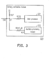
- FIG. 3 illustrates an implementation of a battery verification module 220 according to an embodiment of the disclosure.
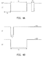
- FIG. 4A and FIG. 4B respectively illustrate waveforms of signals transmitted between a battery verification module and a battery module.
- FIG. 5 illustrates another implementation of the battery verification module 220 according to an embodiment of the disclosure.
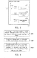
- FIG. 6 is a flowchart of a method for verifying a battery module connected to an electrical apparatus according to an embodiment of the disclosure.
- FIG. 2 is a diagram of an electrical apparatus 200 according to an embodiment of the disclosure.
- the electrical apparatus 200 includes a battery module 210 and a battery verification module 220.
- the battery module 210 has a verification circuit 211 and an identification resistor RPL.
- One end of the identification resistor RPL is coupled to a reference voltage GND, and the other end of the identification resistor RPL is coupled to the verification circuit 211.
- the battery verification module 220 has a reference resistor RUP coupled to a reference voltage V1.
- the battery module 210 and the battery verification module 220 respectively have a terminal CN1 and a terminal CN2.
- the reference resistor RUP and the identification resistor RPL are serially connected between the reference voltages V1 and GND. Namely, the voltage on the coupled terminal DT between the reference resistor RUP and the identification resistor RPL is equal to the voltage obtained by dividing the reference voltage V1 according to the resistances of the reference resistor RUP and the identification resistor RPL.
- the battery verification module 220 obtains a type information of the battery module 210 according to the voltage on the terminal DT.
- the type information includes at least one of the label, the model, and the specification of the battery module 210.
- battery modules 210 having different type information have different built-in identification resistors RPL.
- the battery verification module 220 may obtain the type information of the battery module 210 according to the voltage level on the terminal DT.
- the battery verification module 220 transmits a verification request to the verification circuit 211 in the battery module 210. Accordingly, the verification circuit 211 transmits a verification signal to the battery verification module 220 through a coupled path PT1 between the reference resistor RUP and the identification resistor RPL. It should be mentioned that the battery verification module 220 transmits the verification request to the verification circuit 211 in the battery module 210 through the same coupled path PT1.
- the verification circuit 211 is a circuit that may transmit digital or analog verification signal to the terminal CN1. Namely, the verification circuit 211 generates the verification signal by using a serially connected resistor string, an encoding integrated circuit (IC), or a capacitor network. For example, the verification circuit 211 serially connects a resistor string between two different voltage levels and generates the verification signal by using the voltage division produced by the resistor string. Or, the verification circuit 211 provides an encoded digital data generated by an encoding IC as the verification signal. The verification circuit 211 may also generate the verification signal through voltage division or voltage multiplication by using a capacitor network.
- IC encoding integrated circuit
- terminals CN2 and CN1 of the battery verification module 220 and the battery module 210 are both one-wire terminals, signal transmission between the battery verification module 220 and the battery module 210 may be carried out according to a one-wire protocol.
- One-wire protocol refers to a protocol in which data is transmitted between two electrical apparatuses by using a single wire.
- the wire used for transmitting data is pulled to a high voltage level.
- the apparatus A When one electrical apparatus (for example, an apparatus A) is about to transmit data to the other electrical apparatus (for example, an apparatus B), the apparatus A notifies the apparatus B that data is to be transmitted by pulling the voltage on the wire to a low level for a time period. After the apparatus B confirms the data transmission operation to be carried out by the apparatus A, the apparatus A transmits different data (logic 0 or logic 1) by pulling low the voltage level on the wire for different time periods.
- FIG. 3 illustrates an implementation of the battery verification module 220 according to an embodiment of the disclosure.
- the battery verification module 220 further includes a main processor 221, an auxiliary processing module 222, and a voltage dividing resistor RBAT_ID.
- the main processor 221 is coupled to the terminal DT of the reference resistor RUP that is not coupled to the reference voltage V1.
- the auxiliary processing module 222 is coupled to the main processor 221.
- the voltage dividing resistor RBAT_ID is coupled on the coupled path between the auxiliary processing module 222 and the main processor 221.
- the resistance of the voltage dividing resistor RBAT_ID is smaller than the resistance of the reference resistor RUP.
- the main processor 221 is coupled to the terminal DT through a pin of a general purpose input output (GPIO) port thereof and transmits and receives data through the pin of the GPIO port connected to the terminal DT.
- GPIO general purpose input output
- the auxiliary processing module 222 obtains the type information of the battery module 210 according to the voltage on the terminal DT.
- the auxiliary processing module 222 may be an analog-to-digital converter (ADC), and which converts the voltage on the terminal DT from an analog format into a digital format, so that the battery module 210 may obtain the type information of the battery module 210 according to the voltage on the terminal DT in the digital format.
- ADC analog-to-digital converter
- the auxiliary processing module 222 supplies a pull-up voltage VUP to one end of the voltage dividing resistor RBAT_ID (the other end of the voltage dividing resistor RBAT_ID is coupled to the terminal DT). Besides, after the pull-up voltage VUP supplies by the auxiliary processing module 222 stabilizes, the main processor 221 sends a low-level voltage to the terminal DT to pull the voltage level on the terminal DT from the pull-up voltage VUP down to a lower voltage level (for example, the ground voltage). Meanwhile, the verification circuit 211 of the battery module 210 detects that the voltage on the terminal DT is pulled low and accordingly obtains the verification request issued by the battery verification module 220.
- the resistance of the reference resistor RUP is much greater than that of the voltage dividing resistor RBAT_ID.
- the auxiliary processing module 222 supplies the pull-up voltage VUP to one end of the voltage dividing resistor RBAT_ID, the voltage on the terminal DT is nearly determined by the pull-up voltage VUP. Namely, herein the voltage on the terminal DT is about equal to the pull-up voltage VUP.
- the main processor 221 supplies a low-level voltage to the terminal DT to pull the voltage on the terminal DT down to the low-level voltage.
- a resistor RESD is serially connected between the main processor 221 and the terminal DT for electrostatic discharge (ESD) protection.
- the main processor 221 sets the terminal thereof coupled to the reference resistor RUP as an input terminal, and the verification circuit 211 supplies the low-level voltage to the terminal DT and sequentially transmits verification signal by pulling down the voltage on the terminal DT.
- the main processor 221 may be coupled to the terminal DT through a pin of the GPIO port thereof and sends a voltage to the terminal DT or receive the voltage on the terminal DT through the pin.
- the auxiliary processing module 222 obtains a voltage variation curve of the battery module 210 by monitoring the voltage variation on the terminal DT.
- auxiliary processing module 222 for supplying the pull-up voltage VUP and receiving the voltage on the terminal DT may be carried out through a pin of a GPIO port of the main processor 221.
- the auxiliary processing module 222 may be built in the main processor 221.
- FIG. 4A and FIG. 4B respectively illustrate waveforms of signals transmitted between a battery verification module and a battery module.
- data transmission between the battery verification module and the battery module is carried through based on a one-wire protocol.
- the auxiliary processing module supplies a pull-up voltage VUP and maintains the voltage level on the terminal DT at approximately the level of the pull-up voltage VUP.
- the main processor supplies a low-level voltage to continuously pull down the voltage level on the terminal DT.
- the battery module pulls down the voltage on the terminal DT to transmit an acknowledgement signal to the battery verification module.
- the terminal of the main processor coupled to the terminal DT is set as an input terminal for receiving a voltage variation on the terminal DT produced by the battery module, so that the main processor may receive the verification signal issued by the verification circuit and verify the battery module according to the verification signal.
- the verification circuit may transmit the logic verification signal by pulling down the voltage on the terminal DT for different time periods. Taking the waveform 410 as an example, the verification circuit pulls down the voltage on the terminal DT for a time period TL to transmit a logic signal "1". Moreover, taking the waveform 420 as an example, the verification circuit pulls down the voltage on the terminal DT for a time period TH to transmit a logic signal "0", wherein the time period TH is longer than the time period TL.
- the correspondence between the logic signal "1" or “0" and the time period of pulling down the voltage on the terminal DT is not limited in the disclosure and may be changed.
- FIG. 5 illustrates another implementation of the battery verification module 220 according to an embodiment of the disclosure.
- the battery verification module 220 includes a main processor 221, auxiliary processing modules 223 and 224, voltage dividing resistors RBAT and RBAT_ID, and a resistor RESD.
- the battery verification module 220 includes two auxiliary processing modules 223 and 224.
- One of the auxiliary processing modules 223 and 224 supplies a pull-up voltage when the verification request is performed, and the other one of the auxiliary processing modules 223 and 224 is an ADC for detecting the voltage on the terminal DT before the verification request is performed.
- auxiliary processing module 223 or 224 served as the ADC may also obtain a voltage variation curve of the battery module 210 by monitoring the voltage variation on the terminal DT after the verification request is completed.
- FIG. 6 is a flowchart of a method for verifying a battery module of an electrical apparatus according to an embodiment of the disclosure.
- the electrical apparatus has a battery verification module.
- the verification method in the present embodiment includes following steps. First, a voltage level on a coupled terminal of the battery verification module and the battery module is read, and a type information of the battery module is obtained according to the voltage level (S610). Then, a verification request is transmitted by the battery verification module to the verification circuit (S620). Finally, a verification signal is transmitted by the verification circuit to the battery verification module according to the verification request through the coupled terminal of the battery verification module and the battery module (S630). Namely, the verification signal is transmitted to the battery verification module based on a one-wire protocol.
- the type information of a battery module is obtained according to the voltage on the coupled terminal of a battery verification module and the battery module, and a verification signal is transmitted to the battery verification module by the battery module, so that the battery module may be effectively verified by the battery verification module. Accordingly, an original battery module conforming to the manufacturer's specification may pass the verification, while any non-original battery module may be detected. Thus, any damage caused by non-original battery on an electrical apparatus may be effectively avoided.
Landscapes
- Engineering & Computer Science (AREA)
- Power Engineering (AREA)
- Secondary Cells (AREA)
Applications Claiming Priority (1)
| Application Number | Priority Date | Filing Date | Title |
|---|---|---|---|
| US13/150,273 US8912749B2 (en) | 2011-06-01 | 2011-06-01 | Electrical apparatus and verification method for battery module thereof |
Publications (2)
| Publication Number | Publication Date |
|---|---|
| EP2530807A1 true EP2530807A1 (de) | 2012-12-05 |
| EP2530807B1 EP2530807B1 (de) | 2014-01-22 |
Family
ID=45656327
Family Applications (1)
| Application Number | Title | Priority Date | Filing Date |
|---|---|---|---|
| EP12156392.8A Active EP2530807B1 (de) | 2011-06-01 | 2012-02-21 | Elektrische Vorrichtung und Verifizierungsverfahren eines dafür vorgesehenen Batteriemoduls |
Country Status (2)
| Country | Link |
|---|---|
| US (1) | US8912749B2 (de) |
| EP (1) | EP2530807B1 (de) |
Cited By (2)
| Publication number | Priority date | Publication date | Assignee | Title |
|---|---|---|---|---|
| WO2015007523A1 (en) * | 2013-07-18 | 2015-01-22 | Koninklijke Philips N.V. | Dc power distribution system |
| EP4583359A1 (de) * | 2024-01-04 | 2025-07-09 | Samsung Sdi Co., Ltd. | Verfahren und vorrichtung zur einstellung eines batteriepackidentifikators |
Families Citing this family (4)
| Publication number | Priority date | Publication date | Assignee | Title |
|---|---|---|---|---|
| US9739681B2 (en) | 2014-10-29 | 2017-08-22 | Kulite Semiconductor Products, Inc. | Systems and methods for electrically identifying and compensating individual pressure transducers |
| US12170450B2 (en) | 2020-11-20 | 2024-12-17 | Milwaukee Electric Tool Corporation | Systems and methods for identifying a battery pack for a battery pack powered power tool |
| KR20260018609A (ko) * | 2024-07-31 | 2026-02-09 | 삼성에스디아이 주식회사 | 다수의 이차전지 모듈 지원이 가능한 배터리 관리 장치 |
| KR20260050883A (ko) * | 2024-10-08 | 2026-04-15 | 삼성에스디아이 주식회사 | 인증 회로부가 적용되는 배터리 보호회로 모듈 및 이를 이용한 인증 회로부 보호 방법 |
Citations (4)
| Publication number | Priority date | Publication date | Assignee | Title |
|---|---|---|---|---|
| US5237257A (en) * | 1989-04-21 | 1993-08-17 | Motorola, Inc. | Method and apparatus for determining battery type and modifying operating characteristics |
| US5608306A (en) * | 1994-03-15 | 1997-03-04 | Ericsson Inc. | Rechargeable battery pack with identification circuit, real time clock and authentication capability |
| US6112105A (en) * | 1997-10-28 | 2000-08-29 | Telefonaktiebolaget Lm Ericsson | Identification arrangement and method |
| US20070123303A1 (en) * | 2005-10-14 | 2007-05-31 | Christopher Book | Mobile device with a smart battery |
Family Cites Families (13)
| Publication number | Priority date | Publication date | Assignee | Title |
|---|---|---|---|---|
| US5184059A (en) | 1991-09-16 | 1993-02-02 | Motorola, Inc. | Expanded battery capacity identification scheme and apparatus |
| US5200686A (en) | 1991-10-10 | 1993-04-06 | Motorola, Inc. | Method and apparatus for determining battery type |
| JP2802333B2 (ja) | 1995-01-25 | 1998-09-24 | 株式会社バンダイ | 成形装置 |
| EP1199783A1 (de) | 2000-10-16 | 2002-04-24 | Sony International (Europe) GmbH | System zur Wartung einer Batterie |
| US20030034757A1 (en) * | 2000-12-04 | 2003-02-20 | Woodnorth Douglas J. | Utilizing portable electrical power sources |
| KR100690729B1 (ko) | 2004-10-04 | 2007-03-09 | 엘지전자 주식회사 | 이동 통신 단말기의 배터리 구분 동작 온/오프 장치 및 방법 |
| CA2625186C (en) | 2005-10-14 | 2014-02-11 | Research In Motion Limited | Battery pack authentication for a mobile device |
| US20080238357A1 (en) * | 2007-03-26 | 2008-10-02 | Bourilkov Jordan T | Ultra fast battery charger with battery sensing |
| US8242742B2 (en) | 2007-06-06 | 2012-08-14 | O2Micro, Inc | Chargers, systems and methods for detecting a power source |
| TWI448035B (zh) | 2008-07-04 | 2014-08-01 | Chi Mei Comm Systems Inc | 電池溫度偵測系統及方法 |
| WO2010036202A1 (en) | 2008-09-23 | 2010-04-01 | Stl Energy Technology (S) Pte Ltd | Battery pack and method of battery pack power management |
| US9762069B2 (en) * | 2009-05-19 | 2017-09-12 | Duracell U.S. Operations, Inc. | Multi-use fast rate charging stand |
| US20100308771A1 (en) | 2009-06-04 | 2010-12-09 | William Densham | System and method for protection of battery pack |
-
2011
- 2011-06-01 US US13/150,273 patent/US8912749B2/en active Active
-
2012
- 2012-02-21 EP EP12156392.8A patent/EP2530807B1/de active Active
Patent Citations (4)
| Publication number | Priority date | Publication date | Assignee | Title |
|---|---|---|---|---|
| US5237257A (en) * | 1989-04-21 | 1993-08-17 | Motorola, Inc. | Method and apparatus for determining battery type and modifying operating characteristics |
| US5608306A (en) * | 1994-03-15 | 1997-03-04 | Ericsson Inc. | Rechargeable battery pack with identification circuit, real time clock and authentication capability |
| US6112105A (en) * | 1997-10-28 | 2000-08-29 | Telefonaktiebolaget Lm Ericsson | Identification arrangement and method |
| US20070123303A1 (en) * | 2005-10-14 | 2007-05-31 | Christopher Book | Mobile device with a smart battery |
Cited By (3)
| Publication number | Priority date | Publication date | Assignee | Title |
|---|---|---|---|---|
| WO2015007523A1 (en) * | 2013-07-18 | 2015-01-22 | Koninklijke Philips N.V. | Dc power distribution system |
| US10044183B2 (en) | 2013-07-18 | 2018-08-07 | Philips Lighting Holding B.V. | DC power distribution system |
| EP4583359A1 (de) * | 2024-01-04 | 2025-07-09 | Samsung Sdi Co., Ltd. | Verfahren und vorrichtung zur einstellung eines batteriepackidentifikators |
Also Published As
| Publication number | Publication date |
|---|---|
| US20120306505A1 (en) | 2012-12-06 |
| US8912749B2 (en) | 2014-12-16 |
| EP2530807B1 (de) | 2014-01-22 |
Similar Documents
| Publication | Publication Date | Title |
|---|---|---|
| CN102820970B (zh) | 电子装置及其电池模块的认证方法 | |
| JP5717005B2 (ja) | Usbインタフェースのステータスに従って内部回路を選択するための方法および端末 | |
| EP2530807A1 (de) | Elektrische Vorrichtung und Verifizierungsverfahren für ein Batteriemodul dafür | |
| US9153984B2 (en) | Charging device | |
| US7631203B2 (en) | Dedicated power supply apparatus, terminal, power supply system, and power supply method | |
| CN101320080B (zh) | 电源检测电路、系统及方法 | |
| EP1950668B1 (de) | Zeitsteuerung von einem Zustandsübergang einer seriellen Datenleitung in einer I2C-Steuerung | |
| US8796988B2 (en) | Input-output circuit | |
| CN102694400B (zh) | 输入输出电路 | |
| US8749221B2 (en) | Input-output circuit | |
| EP2713280A2 (de) | Handgeführte vorrichtung, usb-ladegerät und verfahren zur identifizierung des usb-ladegerätes durch die handgeführte vorrichtung | |
| US9223727B2 (en) | Input-output circuit | |
| US20130207594A1 (en) | Portable electronic devices and charging method thereof | |
| EP2863648B1 (de) | Verfahren und vorrichtung zur selbstanpassung von audioschnittstellen | |
| CN114039400B (zh) | 一种电子设备 | |
| CN201260086Y (zh) | 移动终端及其充电检测装置 | |
| US20160079775A1 (en) | Charging Current Setting Method and Charging Module | |
| CN100530812C (zh) | 一种被充电侧检测外部充电电源充电方式的方法及装置 | |
| CN106487061B (zh) | 充电电路及方法 | |
| TWI423555B (zh) | 電子裝置及其電池模組的認證方法 | |
| CN103633686B (zh) | 用于修正充电错误的系统、方法 | |
| US12620998B2 (en) | Methods and circuits for electrical power supply | |
| US20240250691A1 (en) | Methods and circuits for electrical power supply | |
| CN1976163A (zh) | 充电器类型判别系统、终端充电方法、终端和充电器 | |
| CN115575711A (zh) | 充电线路的阻抗检测方法、阻抗检测装置及移动终端 |
Legal Events
| Date | Code | Title | Description |
|---|---|---|---|
| PUAI | Public reference made under article 153(3) epc to a published international application that has entered the european phase |
Free format text: ORIGINAL CODE: 0009012 |
|
| 17P | Request for examination filed |
Effective date: 20120222 |
|
| AK | Designated contracting states |
Kind code of ref document: A1 Designated state(s): AL AT BE BG CH CY CZ DE DK EE ES FI FR GB GR HR HU IE IS IT LI LT LU LV MC MK MT NL NO PL PT RO RS SE SI SK SM TR |
|
| AX | Request for extension of the european patent |
Extension state: BA ME |
|
| RIC1 | Information provided on ipc code assigned before grant |
Ipc: H02J 7/00 20060101AFI20130621BHEP |
|
| RBV | Designated contracting states (corrected) |
Designated state(s): AL AT BE BG CH CY CZ DE DK EE ES FI FR GB GR HR HU IE IS IT LI LT LU LV MC MK MT NL NO PL PT RO RS SE SI SK SM TR |
|
| GRAP | Despatch of communication of intention to grant a patent |
Free format text: ORIGINAL CODE: EPIDOSNIGR1 |
|
| INTG | Intention to grant announced |
Effective date: 20130906 |
|
| GRAJ | Information related to disapproval of communication of intention to grant by the applicant or resumption of examination proceedings by the epo deleted |
Free format text: ORIGINAL CODE: EPIDOSDIGR1 |
|
| GRAP | Despatch of communication of intention to grant a patent |
Free format text: ORIGINAL CODE: EPIDOSNIGR1 |
|
| GRAS | Grant fee paid |
Free format text: ORIGINAL CODE: EPIDOSNIGR3 |
|
| INTG | Intention to grant announced |
Effective date: 20131119 |
|
| GRAA | (expected) grant |
Free format text: ORIGINAL CODE: 0009210 |
|
| AK | Designated contracting states |
Kind code of ref document: B1 Designated state(s): AL AT BE BG CH CY CZ DE DK EE ES FI FR GB GR HR HU IE IS IT LI LT LU LV MC MK MT NL NO PL PT RO RS SE SI SK SM TR |
|
| REG | Reference to a national code |
Ref country code: GB Ref legal event code: FG4D |
|
| REG | Reference to a national code |
Ref country code: CH Ref legal event code: EP |
|
| REG | Reference to a national code |
Ref country code: AT Ref legal event code: REF Ref document number: 651165 Country of ref document: AT Kind code of ref document: T Effective date: 20140215 |
|
| REG | Reference to a national code |
Ref country code: IE Ref legal event code: FG4D Ref country code: NL Ref legal event code: T3 |
|
| REG | Reference to a national code |
Ref country code: DE Ref legal event code: R096 Ref document number: 602012000833 Country of ref document: DE Effective date: 20140306 |
|
| REG | Reference to a national code |
Ref country code: AT Ref legal event code: MK05 Ref document number: 651165 Country of ref document: AT Kind code of ref document: T Effective date: 20140122 |
|
| REG | Reference to a national code |
Ref country code: LT Ref legal event code: MG4D |
|
| PG25 | Lapsed in a contracting state [announced via postgrant information from national office to epo] |
Ref country code: IS Free format text: LAPSE BECAUSE OF FAILURE TO SUBMIT A TRANSLATION OF THE DESCRIPTION OR TO PAY THE FEE WITHIN THE PRESCRIBED TIME-LIMIT Effective date: 20140522 Ref country code: NO Free format text: LAPSE BECAUSE OF FAILURE TO SUBMIT A TRANSLATION OF THE DESCRIPTION OR TO PAY THE FEE WITHIN THE PRESCRIBED TIME-LIMIT Effective date: 20140422 Ref country code: LT Free format text: LAPSE BECAUSE OF FAILURE TO SUBMIT A TRANSLATION OF THE DESCRIPTION OR TO PAY THE FEE WITHIN THE PRESCRIBED TIME-LIMIT Effective date: 20140122 |
|
| PG25 | Lapsed in a contracting state [announced via postgrant information from national office to epo] |
Ref country code: SE Free format text: LAPSE BECAUSE OF FAILURE TO SUBMIT A TRANSLATION OF THE DESCRIPTION OR TO PAY THE FEE WITHIN THE PRESCRIBED TIME-LIMIT Effective date: 20140122 Ref country code: ES Free format text: LAPSE BECAUSE OF FAILURE TO SUBMIT A TRANSLATION OF THE DESCRIPTION OR TO PAY THE FEE WITHIN THE PRESCRIBED TIME-LIMIT Effective date: 20140122 Ref country code: AT Free format text: LAPSE BECAUSE OF FAILURE TO SUBMIT A TRANSLATION OF THE DESCRIPTION OR TO PAY THE FEE WITHIN THE PRESCRIBED TIME-LIMIT Effective date: 20140122 Ref country code: FI Free format text: LAPSE BECAUSE OF FAILURE TO SUBMIT A TRANSLATION OF THE DESCRIPTION OR TO PAY THE FEE WITHIN THE PRESCRIBED TIME-LIMIT Effective date: 20140122 Ref country code: PT Free format text: LAPSE BECAUSE OF FAILURE TO SUBMIT A TRANSLATION OF THE DESCRIPTION OR TO PAY THE FEE WITHIN THE PRESCRIBED TIME-LIMIT Effective date: 20140522 Ref country code: CY Free format text: LAPSE BECAUSE OF FAILURE TO SUBMIT A TRANSLATION OF THE DESCRIPTION OR TO PAY THE FEE WITHIN THE PRESCRIBED TIME-LIMIT Effective date: 20140122 |
|
| PG25 | Lapsed in a contracting state [announced via postgrant information from national office to epo] |
Ref country code: LV Free format text: LAPSE BECAUSE OF FAILURE TO SUBMIT A TRANSLATION OF THE DESCRIPTION OR TO PAY THE FEE WITHIN THE PRESCRIBED TIME-LIMIT Effective date: 20140122 Ref country code: RS Free format text: LAPSE BECAUSE OF FAILURE TO SUBMIT A TRANSLATION OF THE DESCRIPTION OR TO PAY THE FEE WITHIN THE PRESCRIBED TIME-LIMIT Effective date: 20140122 Ref country code: BE Free format text: LAPSE BECAUSE OF FAILURE TO SUBMIT A TRANSLATION OF THE DESCRIPTION OR TO PAY THE FEE WITHIN THE PRESCRIBED TIME-LIMIT Effective date: 20140122 Ref country code: HR Free format text: LAPSE BECAUSE OF FAILURE TO SUBMIT A TRANSLATION OF THE DESCRIPTION OR TO PAY THE FEE WITHIN THE PRESCRIBED TIME-LIMIT Effective date: 20140122 |
|
| REG | Reference to a national code |
Ref country code: DE Ref legal event code: R097 Ref document number: 602012000833 Country of ref document: DE |
|
| PG25 | Lapsed in a contracting state [announced via postgrant information from national office to epo] |
Ref country code: MC Free format text: LAPSE BECAUSE OF FAILURE TO SUBMIT A TRANSLATION OF THE DESCRIPTION OR TO PAY THE FEE WITHIN THE PRESCRIBED TIME-LIMIT Effective date: 20140122 Ref country code: CZ Free format text: LAPSE BECAUSE OF FAILURE TO SUBMIT A TRANSLATION OF THE DESCRIPTION OR TO PAY THE FEE WITHIN THE PRESCRIBED TIME-LIMIT Effective date: 20140122 Ref country code: EE Free format text: LAPSE BECAUSE OF FAILURE TO SUBMIT A TRANSLATION OF THE DESCRIPTION OR TO PAY THE FEE WITHIN THE PRESCRIBED TIME-LIMIT Effective date: 20140122 Ref country code: RO Free format text: LAPSE BECAUSE OF FAILURE TO SUBMIT A TRANSLATION OF THE DESCRIPTION OR TO PAY THE FEE WITHIN THE PRESCRIBED TIME-LIMIT Effective date: 20140122 Ref country code: DK Free format text: LAPSE BECAUSE OF FAILURE TO SUBMIT A TRANSLATION OF THE DESCRIPTION OR TO PAY THE FEE WITHIN THE PRESCRIBED TIME-LIMIT Effective date: 20140122 |
|
| PG25 | Lapsed in a contracting state [announced via postgrant information from national office to epo] |
Ref country code: PL Free format text: LAPSE BECAUSE OF FAILURE TO SUBMIT A TRANSLATION OF THE DESCRIPTION OR TO PAY THE FEE WITHIN THE PRESCRIBED TIME-LIMIT Effective date: 20140122 Ref country code: SK Free format text: LAPSE BECAUSE OF FAILURE TO SUBMIT A TRANSLATION OF THE DESCRIPTION OR TO PAY THE FEE WITHIN THE PRESCRIBED TIME-LIMIT Effective date: 20140122 |
|
| PLBE | No opposition filed within time limit |
Free format text: ORIGINAL CODE: 0009261 |
|
| STAA | Information on the status of an ep patent application or granted ep patent |
Free format text: STATUS: NO OPPOSITION FILED WITHIN TIME LIMIT |
|
| REG | Reference to a national code |
Ref country code: IE Ref legal event code: MM4A |
|
| 26N | No opposition filed |
Effective date: 20141023 |
|
| PG25 | Lapsed in a contracting state [announced via postgrant information from national office to epo] |
Ref country code: IE Free format text: LAPSE BECAUSE OF NON-PAYMENT OF DUE FEES Effective date: 20140221 |
|
| REG | Reference to a national code |
Ref country code: DE Ref legal event code: R097 Ref document number: 602012000833 Country of ref document: DE Effective date: 20141023 |
|
| REG | Reference to a national code |
Ref country code: CH Ref legal event code: PCOW Free format text: NEW ADDRESS: NO. 23, XINGHUA ROAD TAOYUAN DISTRICT, TAOYUAN CITY 330 (TW) |
|
| PG25 | Lapsed in a contracting state [announced via postgrant information from national office to epo] |
Ref country code: SI Free format text: LAPSE BECAUSE OF FAILURE TO SUBMIT A TRANSLATION OF THE DESCRIPTION OR TO PAY THE FEE WITHIN THE PRESCRIBED TIME-LIMIT Effective date: 20140122 |
|
| REG | Reference to a national code |
Ref country code: CH Ref legal event code: PL |
|
| PG25 | Lapsed in a contracting state [announced via postgrant information from national office to epo] |
Ref country code: LI Free format text: LAPSE BECAUSE OF NON-PAYMENT OF DUE FEES Effective date: 20150228 Ref country code: CH Free format text: LAPSE BECAUSE OF NON-PAYMENT OF DUE FEES Effective date: 20150228 |
|
| REG | Reference to a national code |
Ref country code: FR Ref legal event code: PLFP Year of fee payment: 5 |
|
| PG25 | Lapsed in a contracting state [announced via postgrant information from national office to epo] |
Ref country code: MT Free format text: LAPSE BECAUSE OF FAILURE TO SUBMIT A TRANSLATION OF THE DESCRIPTION OR TO PAY THE FEE WITHIN THE PRESCRIBED TIME-LIMIT Effective date: 20140122 |
|
| PG25 | Lapsed in a contracting state [announced via postgrant information from national office to epo] |
Ref country code: SM Free format text: LAPSE BECAUSE OF FAILURE TO SUBMIT A TRANSLATION OF THE DESCRIPTION OR TO PAY THE FEE WITHIN THE PRESCRIBED TIME-LIMIT Effective date: 20140122 |
|
| PG25 | Lapsed in a contracting state [announced via postgrant information from national office to epo] |
Ref country code: GR Free format text: LAPSE BECAUSE OF FAILURE TO SUBMIT A TRANSLATION OF THE DESCRIPTION OR TO PAY THE FEE WITHIN THE PRESCRIBED TIME-LIMIT Effective date: 20140423 Ref country code: BG Free format text: LAPSE BECAUSE OF FAILURE TO SUBMIT A TRANSLATION OF THE DESCRIPTION OR TO PAY THE FEE WITHIN THE PRESCRIBED TIME-LIMIT Effective date: 20140122 Ref country code: IT Free format text: LAPSE BECAUSE OF FAILURE TO SUBMIT A TRANSLATION OF THE DESCRIPTION OR TO PAY THE FEE WITHIN THE PRESCRIBED TIME-LIMIT Effective date: 20140122 |
|
| PG25 | Lapsed in a contracting state [announced via postgrant information from national office to epo] |
Ref country code: TR Free format text: LAPSE BECAUSE OF FAILURE TO SUBMIT A TRANSLATION OF THE DESCRIPTION OR TO PAY THE FEE WITHIN THE PRESCRIBED TIME-LIMIT Effective date: 20140122 Ref country code: HU Free format text: LAPSE BECAUSE OF FAILURE TO SUBMIT A TRANSLATION OF THE DESCRIPTION OR TO PAY THE FEE WITHIN THE PRESCRIBED TIME-LIMIT; INVALID AB INITIO Effective date: 20120221 Ref country code: LU Free format text: LAPSE BECAUSE OF NON-PAYMENT OF DUE FEES Effective date: 20140221 |
|
| REG | Reference to a national code |
Ref country code: FR Ref legal event code: PLFP Year of fee payment: 6 |
|
| REG | Reference to a national code |
Ref country code: FR Ref legal event code: PLFP Year of fee payment: 7 |
|
| PG25 | Lapsed in a contracting state [announced via postgrant information from national office to epo] |
Ref country code: MK Free format text: LAPSE BECAUSE OF FAILURE TO SUBMIT A TRANSLATION OF THE DESCRIPTION OR TO PAY THE FEE WITHIN THE PRESCRIBED TIME-LIMIT Effective date: 20140122 |
|
| PG25 | Lapsed in a contracting state [announced via postgrant information from national office to epo] |
Ref country code: AL Free format text: LAPSE BECAUSE OF FAILURE TO SUBMIT A TRANSLATION OF THE DESCRIPTION OR TO PAY THE FEE WITHIN THE PRESCRIBED TIME-LIMIT Effective date: 20140122 |
|
| P01 | Opt-out of the competence of the unified patent court (upc) registered |
Effective date: 20230602 |
|
| PGFP | Annual fee paid to national office [announced via postgrant information from national office to epo] |
Ref country code: FR Payment date: 20251208 Year of fee payment: 15 |
|
| PGFP | Annual fee paid to national office [announced via postgrant information from national office to epo] |
Ref country code: NL Payment date: 20260106 Year of fee payment: 15 |
|
| PGFP | Annual fee paid to national office [announced via postgrant information from national office to epo] |
Ref country code: GB Payment date: 20260106 Year of fee payment: 15 |
|
| PGFP | Annual fee paid to national office [announced via postgrant information from national office to epo] |
Ref country code: DE Payment date: 20251230 Year of fee payment: 15 |