EP2531680B1 - Fahrzeugverriegelung mit doppelklinkenanordnung - Google Patents
Fahrzeugverriegelung mit doppelklinkenanordnung Download PDFInfo
- Publication number
- EP2531680B1 EP2531680B1 EP10844969.5A EP10844969A EP2531680B1 EP 2531680 B1 EP2531680 B1 EP 2531680B1 EP 10844969 A EP10844969 A EP 10844969A EP 2531680 B1 EP2531680 B1 EP 2531680B1
- Authority
- EP
- European Patent Office
- Prior art keywords
- ratchet
- pawl
- auxiliary
- auxiliary ratchet
- secondary pawl
- Prior art date
- Legal status (The legal status is an assumption and is not a legal conclusion. Google has not performed a legal analysis and makes no representation as to the accuracy of the status listed.)
- Active
Links
Images


Classifications
-
- E—FIXED CONSTRUCTIONS
- E05—LOCKS; KEYS; WINDOW OR DOOR FITTINGS; SAFES
- E05B—LOCKS; ACCESSORIES THEREFOR; HANDCUFFS
- E05B81/00—Power-actuated vehicle locks
- E05B81/12—Power-actuated vehicle locks characterised by the function or purpose of the powered actuators
- E05B81/14—Power-actuated vehicle locks characterised by the function or purpose of the powered actuators operating on bolt detents, e.g. for unlatching the bolt
-
- E—FIXED CONSTRUCTIONS
- E05—LOCKS; KEYS; WINDOW OR DOOR FITTINGS; SAFES
- E05B—LOCKS; ACCESSORIES THEREFOR; HANDCUFFS
- E05B81/00—Power-actuated vehicle locks
- E05B81/54—Electrical circuits
- E05B81/64—Monitoring or sensing, e.g. by using switches or sensors
- E05B81/70—Monitoring or sensing, e.g. by using switches or sensors the wing position
-
- E—FIXED CONSTRUCTIONS
- E05—LOCKS; KEYS; WINDOW OR DOOR FITTINGS; SAFES
- E05B—LOCKS; ACCESSORIES THEREFOR; HANDCUFFS
- E05B85/00—Details of vehicle locks not provided for in groups E05B77/00 - E05B83/00
- E05B85/20—Bolts or detents
- E05B85/24—Bolts rotating about an axis
- E05B85/26—Cooperation between bolts and detents
-
- E—FIXED CONSTRUCTIONS
- E05—LOCKS; KEYS; WINDOW OR DOOR FITTINGS; SAFES
- E05B—LOCKS; ACCESSORIES THEREFOR; HANDCUFFS
- E05B77/00—Vehicle locks characterised by special functions or purposes
- E05B77/02—Vehicle locks characterised by special functions or purposes for accident situations
- E05B77/04—Preventing unwanted lock actuation, e.g. unlatching, at the moment of collision
- E05B77/06—Preventing unwanted lock actuation, e.g. unlatching, at the moment of collision by means of inertial forces
-
- E—FIXED CONSTRUCTIONS
- E05—LOCKS; KEYS; WINDOW OR DOOR FITTINGS; SAFES
- E05B—LOCKS; ACCESSORIES THEREFOR; HANDCUFFS
- E05B81/00—Power-actuated vehicle locks
- E05B81/54—Electrical circuits
- E05B81/90—Manual override in case of power failure
-
- Y—GENERAL TAGGING OF NEW TECHNOLOGICAL DEVELOPMENTS; GENERAL TAGGING OF CROSS-SECTIONAL TECHNOLOGIES SPANNING OVER SEVERAL SECTIONS OF THE IPC; TECHNICAL SUBJECTS COVERED BY FORMER USPC CROSS-REFERENCE ART COLLECTIONS [XRACs] AND DIGESTS
- Y10—TECHNICAL SUBJECTS COVERED BY FORMER USPC
- Y10S—TECHNICAL SUBJECTS COVERED BY FORMER USPC CROSS-REFERENCE ART COLLECTIONS [XRACs] AND DIGESTS
- Y10S292/00—Closure fasteners
- Y10S292/23—Vehicle door latches
-
- Y—GENERAL TAGGING OF NEW TECHNOLOGICAL DEVELOPMENTS; GENERAL TAGGING OF CROSS-SECTIONAL TECHNOLOGIES SPANNING OVER SEVERAL SECTIONS OF THE IPC; TECHNICAL SUBJECTS COVERED BY FORMER USPC CROSS-REFERENCE ART COLLECTIONS [XRACs] AND DIGESTS
- Y10—TECHNICAL SUBJECTS COVERED BY FORMER USPC
- Y10T—TECHNICAL SUBJECTS COVERED BY FORMER US CLASSIFICATION
- Y10T292/00—Closure fasteners
- Y10T292/08—Bolts
- Y10T292/1043—Swinging
- Y10T292/1044—Multiple head
- Y10T292/1045—Operating means
- Y10T292/1047—Closure
-
- Y—GENERAL TAGGING OF NEW TECHNOLOGICAL DEVELOPMENTS; GENERAL TAGGING OF CROSS-SECTIONAL TECHNOLOGIES SPANNING OVER SEVERAL SECTIONS OF THE IPC; TECHNICAL SUBJECTS COVERED BY FORMER USPC CROSS-REFERENCE ART COLLECTIONS [XRACs] AND DIGESTS
- Y10—TECHNICAL SUBJECTS COVERED BY FORMER USPC
- Y10T—TECHNICAL SUBJECTS COVERED BY FORMER US CLASSIFICATION
- Y10T292/00—Closure fasteners
- Y10T292/08—Bolts
- Y10T292/1043—Swinging
- Y10T292/1075—Operating means
- Y10T292/1079—Gear
-
- Y—GENERAL TAGGING OF NEW TECHNOLOGICAL DEVELOPMENTS; GENERAL TAGGING OF CROSS-SECTIONAL TECHNOLOGIES SPANNING OVER SEVERAL SECTIONS OF THE IPC; TECHNICAL SUBJECTS COVERED BY FORMER USPC CROSS-REFERENCE ART COLLECTIONS [XRACs] AND DIGESTS
- Y10—TECHNICAL SUBJECTS COVERED BY FORMER USPC
- Y10T—TECHNICAL SUBJECTS COVERED BY FORMER US CLASSIFICATION
- Y10T292/00—Closure fasteners
- Y10T292/08—Bolts
- Y10T292/1043—Swinging
- Y10T292/1075—Operating means
- Y10T292/108—Lever
-
- Y—GENERAL TAGGING OF NEW TECHNOLOGICAL DEVELOPMENTS; GENERAL TAGGING OF CROSS-SECTIONAL TECHNOLOGIES SPANNING OVER SEVERAL SECTIONS OF THE IPC; TECHNICAL SUBJECTS COVERED BY FORMER USPC CROSS-REFERENCE ART COLLECTIONS [XRACs] AND DIGESTS
- Y10—TECHNICAL SUBJECTS COVERED BY FORMER USPC
- Y10T—TECHNICAL SUBJECTS COVERED BY FORMER US CLASSIFICATION
- Y10T292/00—Closure fasteners
- Y10T292/08—Bolts
- Y10T292/1043—Swinging
- Y10T292/1075—Operating means
- Y10T292/1082—Motor
-
- Y—GENERAL TAGGING OF NEW TECHNOLOGICAL DEVELOPMENTS; GENERAL TAGGING OF CROSS-SECTIONAL TECHNOLOGIES SPANNING OVER SEVERAL SECTIONS OF THE IPC; TECHNICAL SUBJECTS COVERED BY FORMER USPC CROSS-REFERENCE ART COLLECTIONS [XRACs] AND DIGESTS
- Y10—TECHNICAL SUBJECTS COVERED BY FORMER USPC
- Y10T—TECHNICAL SUBJECTS COVERED BY FORMER US CLASSIFICATION
- Y10T292/00—Closure fasteners
- Y10T292/08—Bolts
- Y10T292/1043—Swinging
- Y10T292/1075—Operating means
- Y10T292/1083—Rigid
- Y10T292/1092—Swinging catch
Definitions
- the invention generally relates to the art of vehicular latches and more specifically vehicular latches that utilize double pawl arrangements.
- Double pawl arrangements are known in the latching art.
- the double pawl arrangement may utilize a first pawl and ratchet set connected to a second pawl and ratchet.
- the connection may be configured such that only a portion of the forces experienced by the first pawl and ratchet set are applied to the second pawl and ratchet set, thus requiring only a relatively low effort to release the latch. While this is desirable, it also leads to the problem that an unbalanced force may unintentionally release the latch in unintended circumstances such as a crash situation. It would be desirable to preclude such events.
- both pawls must be reset to their locked positions.
- Biasing means such as springs are conventionally employed for such purpose. But over time, these biasing forces may degrade, or may be insufficient occasionally to cope with other impediments to returning the pawls to their respective locked positions. An elegant, low cost solution is sought to such problems.
- a vehicle latch with the features of the preamble of claim 1 is known from WO 2009/143997 A1 .
- the invention relates to a latch having a ratchet, primary pawl, auxiliary ratchet and secondary pawl.
- a drive mechanism interfaces with the secondary pawl and auxiliary ratchet to open and close the latch.
- the auxiliary ratchet is configured to engage and move the secondary pawl upon closing.
- the ratchet is movable between a striker release position wherein the ratchet is positioned to receive a striker and a striker capture position wherein the ratchet is positioned to retain the striker, the ratchet being biased towards the striker release position.
- the primary pawl is movable between a ratchet checking position wherein the primary pawl is positioned to keep the ratchet in the striker capture position and a ratchet release position wherein the primary pawl permits the movement of the ratchet out of the striker capture position.
- the auxiliary ratchet is operatively connected to the primary pawl and is movable between an enabling position in which the primary pawl is enabled to move to its ratchet checking position and a disabling position in which the auxiliary ratchet positions the primary pawl to its ratchet release position.
- a secondary pawl is movable between an auxiliary ratchet holding position, in which the secondary pawl is positioned to hold the auxiliary ratchet in its enabling position, and an auxiliary ratchet release position, in which the secondary pawl is positioned to permit movement of the auxiliary ratchet to its disabling position, the secondary pawl being biased to the auxiliary ratchet holding position.
- the drive mechanism moves the secondary pawl into its auxiliary ratchet release position in a process of opening the latch and later moves the auxiliary ratchet into its enabling position in a process of closing the latch.
- the auxiliary ratchet is configured to engage and move the secondary pawl into its auxiliary ratchet holding position as the auxiliary ratchet moves towards its enabled position.
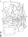
- Fig. 1A is a front view of an electric latch 20 that includes a housing 22 in which a ratchet 24 is pivotally mounted for rotation about a pin 26 mounted in the housing 22.
- the ratchet 24 pivots between a fully closed or striker capture position wherein a striker 28 (shown schematically in stippled lines) is captured by a hook 30 or claw of the ratchet 24, as shown in Fig. 1A , and an open or striker release position wherein the striker 28 is not trapped by the hook or claw 30 and free to move out of the slot presented by the hook or claw.
- the ratchet 24 will rotate clockwise to move into the open or striker release position.
- the ratchet 24 is biased to the open position via a biasing spring (not shown).
- a striker bumper 32 is mounted in the housing 22 (underneath the ratchet 24) to cushion against the striker force of impact and a ratchet bumper 34 is also mounted about a post 36 presented in the housing 22 to cushion against the ratchet force of impact.
- An auxiliary ratchet 44 which may be alternatively referred to as a cam, is also pivotally mounted in the housing 22 via a pin 46 for movement between a closed or enabling position where the auxiliary ratchet abuts the ratchet 24, as shown in Fig. 1A , and an open or disabling position, as discussed in greater detail below. (In the orientation of Figs. 1A the auxiliary ratchet 44 will rotate clockwise to enter the open or disabling position.)
- the auxiliary ratchet 44 includes a cylindrical bore 48 for pivotally mounting a primary pawl 64.
- the primary pawl 64 includes a cylindrical stub 66 for pivotally mounting it into the bore 48 of the auxiliary ratchet 44 - and not the housing 22. This provides a very simple means for mounting the primary pawl 64, which may be formed from a simple stamped or sintered metal piece.
- the auxiliary ratchet 44 also includes a leg 50 which terminates in an anvil 52 having a check shoulder 54 and a cam lip 56.
- the auxiliary ratchet 44 is preferably encapsulated with an elastomeric material and features a hollow 58 so as to provide an elastically deformable band 60 for contacting and absorbing impact against the ratchet 24.
- a biasing spring 45 located on the opposing side of the housing 22 biases the auxiliary ratchet 44 to the open or disabling position.
- the spring 45 features a first tang 45a abutting a capstan 27 of pin 26 and a second tang 45b at an opposite end of the spring 45 which cooperates with a fork (not shown) in the auxiliary ratchet 44 via a slot 23 formed in the housing 22.
- the biasing spring 45 may bias the auxiliary ratchet 45 towards the closed position as discussed in greater detail below.
- the primary pawl 64 includes a check arm 68 extending from the stub 66.
- the check arm 68 pivots between a closed or ratchet checking position in which the check arm 68 stops the opening urge of the ratchet 24, as shown in Fig. 1A , and an open or ratchet release position in which the check arm 68 does not inhibit rotation of the ratchet 24 to its open or striker release position. (In the orientation of Fig. 1A the primary pawl 64 will rotate clockwise to move into the open or ratchet release position.)
- the angular sweep range of the check arm 68 is limited on one side by an edge 63 in the auxiliary ratchet 44 and on the other side by the auxiliary ratchet leg 50.
- a proboscis bumper 72 formed from an encapsulation of the primary pawl 64 may be provided to cushion impact of check arm 68 against the auxiliary ratchet leg 50.
- an extension 33 of the striker bumper 32 may be provided to reduce or cushion impact of check arm 68 against the auxiliary ratchet edge 63.
- the primary pawl 64 is preferably biased to the closed or ratchet checking position by a spring 74 wrapped around a post 76 provided in the anvil 52 of the auxiliary ratchet 44.
- One tang (not visible in Fig. 1A ) of the spring 74 rides against the auxiliary ratchet leg 50, and another tang 78 abuts the check arm 68 of the primary pawl 64.
- the biasing spring 74 is mounted to the auxiliary ratchet 44 rather than the fixed housing 22, the biasing forces on the primary pawl 64 will not vary appreciably as the auxiliary ratchet 44 rotates.
- the ratchet 24 features primary and secondary shoulders 38 and 40 that interact with the check arm 68 of the primary pawl 64.
- Primary shoulder 38 provides a fully closed and locked position of the ratchet 24 in which the striker 28 is securely ensconced in the hook or claw 30 of the ratchet 24 such that the vehicle door (not shown) is completely closed and door seals (not shown) are compressed.
- Secondary shoulder 40 provides a partially closed and locked position of the ratchet 24 wherein the striker 28 is loosely secured in the hook 30 of the ratchet 24 such that the vehicle door is locked but not completely closed against its seals.
- An auxiliary or secondary pawl 84 is also pivotally mounted in the housing 22 about a pin 86 for movement between a closed or auxiliary ratchet holding position where the secondary pawl 84 checks the opening movement of the auxiliary ratchet 44, as shown in Fig. 1A , and an open or auxiliary ratchet release position. (In the orientation of Fig. 1A the primary pawl 84 will rotate counterclockwise to enter the open or auxiliary ratchet release position.)
- the secondary pawl 84 features a hook shoulder 88 for engaging the auxiliary ratchet check shoulder 54 and a protrusion 90, the purpose of which will be discussed below.
- the secondary pawl 84 also includes a first bent tab 92 that projects through an aperture 94 formed in the housing 22 and a second bent tab 93 that projects through another aperture 95 in the housing 22, the purpose of which are also discussed below.
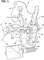
- the secondary pawl 84 is biased to the closed or auxiliary ratchet holding position by a spring 96 (seen partially in Fig. 3 ) disposed about pin 86.
- the latch 20 provides an eccentric double pawl arrangement for lowering release efforts. More particularly, as illustrated in Fig. 3 , there exists a force Fs on the ratchet 24 that is a reaction to the seal force when the vehicle door is closed. The force Fs along with the ratchet bias force presents a moment M1 on the ratchet 24.
- the force necessary to move the primary pawl 64 will thus be related to the coefficient of friction between check arm 68 and ratchet shoulder 38 multiplied by a force approximately X/Y of Fs, where X is the radial distance between the striker and the ratchet pivot point (at pin 26) and Y is the distance between the primary pawl/ratchet contact area and the ratchet pivot point.
- the ratio X/Y could be about 40%.
- the force X/Y*Fs applied to the primary pawl 68 presents a moment M2 about the auxiliary ratchet 44.
- the force necessary to move the secondary pawl 84 will thus be related to the coefficient of friction between secondary pawl hook shoulder 88 and auxiliary ratchet check shoulder 54 multiplied by a force approximately A1/A2 of X/Y* Fs, where A1 is the radial distance between the force on the primary pawl 64 and the auxiliary ratchet pivot point (at pin 46) and A2 is the radial distance between the secondary pawl/auxiliary ratchet contact area and the auxiliary ratchet pivot point.
- the ratio A1/A2 can be as low as 10-20%. Thus, a relatively low release effort may be required to open the latch 20.
- the latch 20 includes a secure lock lever 104 pivotally mounted about a post 106 provided in the housing 22.
- the secure lock lever 104 pivots between a locking position wherein, as shown in Fig. 1B , a thumb 108 of the lock lever engages the bent tab 92 of the secondary pawl 84 in order to check movement of the secondary pawl 84 into its open position, and a releasing position, wherein the thumb 108 does not prohibit movement of the secondary pawl 84 into its open position.
- the secure lock lever 104 will pivot counterclockwise to move into its releasing position.
- a small bumper 110 mounted to the housing 22 sets an angular limit for the secure lock lever 104 in order to align its thumb 108 with the secondary pawl tab 92 when the secure lock lever 104 is in its locking position.
- the secure lock lever 104 features a forked design that includes a longer finger 116 opposing the thumb 108.
- the finger 116 has a bulbous end 118 that cooperates with a gear assembly 140 as discussed in greater detail below.
- the gear assembly 140 includes an electric motor 142 nestled in a compartment formed in the housing 22.
- the motor 142 is controlled by an electronic controller (not shown) which is preferably contained in the latch for applying power to the motor to selectively drive it.
- the motor 142 drives a worm gear 144 which, in turn, drives a gear wheel 146 that is nestled in another compartment in the housing and is mounted for rotation about a post 147 provided therein.
- the gear wheel 146 interacts with the auxiliary ratchet 44, the secondary pawl 84 and the secure lock lever 104. More particularly, as seen best in Fig. 4 , the gear wheel 146 includes a push block 148 that extends axially from a discus 150 of the gear wheel 146. The push block 148 engages a depending wedge-shaped abutment 98 of the secondary pawl 84 that is located inboard of, and supported by, metal tab 93 of the secondary pawl 84.
- the housing aperture 95 ( Fig.
- the gear wheel 146 also includes a first well 160 in the discus 150 that accommodates a depending post 62 of the auxiliary ratchet 44.
- the first well 160 includes radial push surfaces 162, 164 at opposing circumferential ends thereof.
- the gear wheel 146 also includes a second well 166 that is partially co-located with the first well 160 but at an axially different level or plane than the first well 160.
- the second well 166 has a radial cam surface 168 (seen best in Fig.
- the gear wheel 146 also features a circumferential guide surface 170 that at times engages the bulbous end 118 of the secure lock lever 104 as discussed below.
- the secondary pawl 84 can be subject to an inertia force Fi (see Fig. 3 ) that may occur, for example, in the event of a crash.
- the force Fi which does not need to be particularly high given the low release efforts required to open the latch as discussed above, will tend to open the secondary pawl 84.
- the thumb 108 of the secure lock lever 104 advantageously prevents the secondary pawl 84 from pivoting into its open or auxiliary ratchet release position.
- a controller powers the gear assembly 140 to cause the gear wheel 146 to rotate (clockwise in the orientation of Fig. 1B ).
- the cam surface 168 of the gear wheel 146 initially pushes on the bulbous end 118 of finger 116 to move the secure lock lever 104 out of the second gear wheel well 166. Consequently, the secure lock lever thumb 108 is moved out of its blocking position, no longer aligned with tab 92, thus enabling the secondary pawl 84 to pivot to its open or auxiliary ratchet release position.
- the finger 116 of the secure lock lever 104 begins to ride against the gear wheel circumferential guide surface 170.
- the gear wheel push block 148 begins to engage the depending abutment 98 of the secondary pawl 84 to move the secondary pawl 84 into its open or auxiliary ratchet release position.
- the bias force on the auxiliary ratchet 44 and/or reaction to the seal force Fs will typically cause the auxiliary ratchet 44 to spring into its open or disabling position.
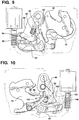
- the gear wheel 146 can function to force the auxiliary ratchet 44 into its open or disabling position. More particularly as seen in the isolated rear image views of Figs. 10 and 11 where the gear wheel 146 is shown in phantom, the controller continues to rotate the gear wheel 146 and in the event the auxiliary ratchet 44 has not yet sprung open the radial push surface 162 of the first gear wheel well 160 will, as shown in Fig. 10 , begin to engage the depending post 62 of the auxiliary ratchet 44 and, as shown in Fig.
- the controller rotates the gear wheel 146 until a limit is reached where the auxiliary ratchet 44 if moved fully into its open or disabling position.
- the limit may signaled by use of a limit switch (such as a "door open” switch, handle switch or both), by sensing a current spike as a result of a part hitting a hard limit, or by reaching a specified time for applying power to the motor gear assembly 140.
- the preferred embodiment employs the switch sensing technique in conjunction with a timeout to avoid unnecessary power consumption, but however the limit is determined when it is reached the controller immediately begins to rotate the gear wheel 146 in the opposite direction to begin a reset operation for the latch before the striker reenters the ratchet 24.
- the motion of the auxiliary ratchet 44 which is driven by the gear wheel 146, can accomplish this function.
- the cam lip 56 of the auxiliary ratchet anvil 52 is configured to engage the protrusion 90 of the secondary pawl in order to pivot and force the secondary pawl 84 back to its closed or auxiliary ratchet holding position.
- the gear assembly 140 is operative to kinematically act on the secondary pawl 84 to move the secondary pawl to its closed or auxiliary ratchet holding position during latch reset.
- the secure lock lever 104 also returns to its locking position (see Fig. 1B ) as the bulbous end 118 of the secure lock lever finger 116 is caught in the second well 166 causing thumb 108 to align with secondary pawl tab 92 and block any opening motion of the secondary pawl 84.
- the auxiliary ratchet 44 is moved to its closed or enabling position, the secondary pawl 84 is moved to its closed or aux ratchet blocking position and the secure lock lever 104 is moved to its locking position.
- the primary pawl 64 is not yet in its closed or ratchet checking position since the check arm 68 merely brushes up against an open ratchet 24. Only when the vehicle is door is closed and the striker reenters the ratchet hook or claw 30 will the ratchet 24 rotate to its closed or striker retaining portion, enabling the bias force present on the primary pawl 64 to move the check arm 68 into blocking position with the ratchet primary shoulder 38 as shown in Fig. 1A (or secondary shoulder 40 in the event of a weakly closed door.)
- the sequence of resetting the latch immediately upon opening has benefits in that in the process of later closing the latch the only moving parts are the ratchet 34 and primary pawl 64, the movements of which have relatively low noise. More importantly, there is no need to synchronize the movement any parts upon closing the latch which could occur very quickly or slowly depending on how fast the vehicle door is closed. The latch is thus not speed sensitive, and thus it is possible to avoid such problems in resetting the latch during closing.
- Figs. 2A and 2B show an alternative embodiment of a latch 20', where like parts are labeled with the same reference numbers as latch 20.
- the latch 20' includes additional mechanism for releasing the secure lock lever 104 from its locked position.
- the mechanism include an emergency release lever 124, rotationally mounted to pin 86, having three limbs 126, 128 and 130, and an intermediate emergency release lever 132, rotationally mounted to a pin integrated on the latch housing, having two limbs 134 and 136.
- the levers 124, 126 are kinematically connected via inter-engaging limbs 126 and 134, such that actuation of the intermediate release lever 132 in the counterclockwise direction (having reference to the orientation of Fig.
- the intermediate release lever 132 also has an appendage 133 that engages and actuates the primary pawl into its open or ratchet release position.
- the intermediate emergency release lever 132 may be actuated by one or more optional levers as follows.
- an inside release lever 138 may be provided in the latch 20' and connected by Bowden cable to an inside handle (not shown).
- the inside release lever 138 is directly connected to the intermediate emergency release lever 132 to actuate it.
- This option may be suitable for an electric latch with a manual back-up from a conventional inside handle.
- an access hole (not shown) may be provided in the latch to enable service personnel to manually move the inside release lever 138 with a tool such as screwdriver.
- This option may be suitable in a full-electric version of latch 20, providing service mechanical emergency release means.
- the inside release lever 138 may be provided in two parts 138a and 138b, with the second part 138b mounted at a common rotational point with lever 138a.
- the second lever 138b directly engages the intermediate release lever 132 and is selectively coupled or uncoupled with the first lever 138a by a link mechanism 139 comprising a motor 139a, gear train 139b, and sliding link 139c.
- the link mechanism 139 provides a double lock function, disabling the inside release lever 138 by selectively de-coupling the first lever 138a from the second lever 138b. This option may be suitable where a dead lock or child lock function is desired.
Landscapes
- Lock And Its Accessories (AREA)
Claims (11)
- Fahrzeugverriegelung, die Folgendes umfasst:eine Ratsche (24), die bewegbar ist zwischen einer Schließbügelfreigabeposition, in der die Ratsche positioniert ist, um einen Schließbügel (30) aufzunehmen, und einer Schließbügelerfassungsposition, in der die Ratsche positioniert ist, um den Schließbügel zu halten, wobei die Ratsche (24) gegenüber der Schließbügelfreigabeposition vorgespannt ist;eine primäre Klinke (64), die bewegbar ist zwischen einer Ratschenrückhalteposition, in der die primäre Klinke positioniert ist, um die Ratsche (24) in der Schließbügelerfassungsposition zu halten, und einer Ratschenfreigabeposition, wobei die primäre Klinke die Bewegung der Ratsche aus der Schließbügelerfassungsposition heraus gestattet;eine zusätzliche Ratsche (44), die operativ mit der primären Klinke (64) verbunden ist, wobei die zusätzliche Ratsche (44) bewegbar ist zwischen einer aktivierenden Position, in der die primäre Klinke (64) aktiviert ist, um sich in ihre Ratschenrückhalteposition zu bewegen, und einer deaktivierenden Position, in der die zusätzliche Ratsche (44) die primäre Klinke (64) in ihrer Ratschenfreigabeposition positioniert;eine sekundäre Klinke (84), die bewegbar ist zwischen einer Position zum Halten der zusätzlichen Ratsche, in der die sekundäre Klinke (84) positioniert ist, um die zusätzliche Ratsche (44) in ihrer aktivierenden Position zu halten, und einer Position zum Freigeben der zusätzlichen Ratsche, in der die sekundäre Klinke (84) positioniert ist, um eine Bewegung der zusätzlichen Ratsche (44) in ihre deaktivierende Position zu gestatten, wobei die sekundäre Klinke (84) gegenüber der Halteposition der zusätzlichen Ratsche vorgespannt ist; undeinen Antriebsmechanismus (140) für ein Bewegen der zusätzlichen Klinke (84) in ihre Position zur Freigabe der zusätzlichen Ratsche in einem Prozess des Öffnens der Verriegelung und für ein späteres Bewegen der zusätzlichen Ratsche (44) in ihre aktivierende Position in einem Prozess des Schließens der Verriegelung;dadurch gekennzeichnet, dass die zusätzliche Ratsche (44) dazu ausgelegt ist, in die sekundäre Klinke (84) einzugreifen und diese in ihre Position zum Halten der zusätzlichen Ratsche zu bewegen, wenn sich die zusätzliche Ratsche (44) in Richtung ihrer aktivierten Position bewegt.
- Fahrzeugverriegelung nach Anspruch 1, wobei die zusätzliche Ratsche (44) ein Bein (50) beinhaltet, das in einem Amboss (52) endet, der eine Rückhalteschulter (54) und eine Nockenlippe (56) aufweist, wobei die Nockenlippe (56) dazu ausgelegt ist, in einen Vorsprung (90) der sekundären Klinke (84) einzugreifen, um die sekundäre Klinke (84) zu schwenken und zurück in ihre Position zum Halten der zusätzlichen Ratsche zu zwingen.
- Fahrzeugverriegelung nach Anspruch 1 oder 2, die ferner einen Sicherheitssperrhebel (104) umfasst, der bewegbar ist zwischen einer sperrenden Position, in welcher der Sicherheitssperrhebel (104) ein Bewegen der sekundären Klinke (84) aus ihrer Position zum Halten der zusätzlichen Ratsche verbietet, und einer freigebenden Position, in welcher der Sicherheitssperrhebel (104) ein Bewegen der sekundären Klinke (84) in ihre Position zum Freigeben der zusätzlichen Ratsche ermöglicht, wobei der Sicherheitssperrhebel (104) in der sperrenden Position vorgespannt ist;
und wobei der Antriebsmechanismus (140) ein Getrieberad (146) beinhaltet, um den Sicherheitssperrhebel (104) in seine freigebende Position zu bewegen und die sekundäre Klinke (84) in ihre Position zum Freigeben der zusätzlichen Ratsche zu bewegen. - Fahrzeugverriegelung nach Anspruch 3, wobei der Antriebsmechanismus (140) ebenfalls die zusätzliche Ratsche (44) in ihre deaktivierende Position bewegt, falls die zusätzliche Ratsche (44) beim Bewegen der sekundären Klinke (84) aus ihrer Position zum Halten der zusätzlichen Ratsche heraus nicht ihre deaktivierende Position erreicht, wobei die primäre Klinke (64) in ihre Ratschenfreigabeposition bewegt wird.
- Fahrzeugverriegelung nach Anspruch 4, wobei der Antriebsmechanismus (140) gesteuert wird, um:zuerst die Verriegelung zu öffnen, um (a) den Sicherheitssperrhebel (104) in seine freigebende Position zu bewegen, (b) die sekundäre Klinke (84) in ihre Position zum Freigeben der zusätzlichen Ratsche zu bewegen, und (c) bei Bedarf die zusätzliche Ratsche (44) in ihre deaktivierende Position zu bewegen, wobei sich die Ratsche (24) in ihre Schließbügelfreigabeposition bewegt;dann, vor dem Bewegen der Ratsche (24) in ihre Schließbügelerfassungsposition, die Verriegelung sofort zurückzusetzen, um (d) die zusätzliche Ratsche (44) in ihre aktivierende Position zu bewegen; (e) der sekundären Klinke (84) zu ermöglichen, sich in ihre Position zum Halten der zusätzlichen Ratsche zu bewegen, und (f) dem Sicherheitssperrhebel (104) zu ermöglichen, sich in seine sperrende Position zu bewegen.
- Fahrzeugverriegelung nach einem der Ansprüche 3 bis 5, wobei:das Getrieberad (146) eine darin befindliche Vertiefung (166) aufweist;der Sicherheitssperrhebel (104) schwenkbar in der Verriegelung montiert ist und einen ersten Abschnitt (108) und einen zweiten, starr verbundenen Abschnitt (118) aufweist, wobei dann, wenn der zweite Abschnitt (118) in der Getrieberadvertiefung (166) positioniert ist, der erste Abschnitt (108) eine Bewegung der sekundären Klinke (84) blockiert und dann, wenn der zweite Abschnitt (118) von dem Antriebsmechanismus (140) aus der Vertiefung (166) bewegt wird, der erste Abschnitt (108) eine Bewegung der zweiten Klinke (84) nicht blockiert.
- Fahrzeugverriegelung nach einem der Ansprüche 3 bis 6, wobei:das Getrieberad (146) eine darin befindliche Vertiefung (160) aufweist;die zusätzliche Ratsche (44) einen Pfosten (62) der zusätzlichen Ratsche aufweist; undder Pfosten (62) der zusätzlichen Ratsche in der Getrieberadvertiefung (160) angeordnet ist und in ihn eine oder mehrere Wände (162, 164) davon eingreifen.
- Fahrzeugverriegelung nach einem der Ansprüche 3 bis 7, wobei:das Getrieberad (146) einen Getrieberadschiebeblock (148) aufweist;die sekundäre Klinke (84) einen Anschlag (98) der sekundären Klinke aufweist; undder Getrieberadschiebeblock (148) in den Anschlag (98) der sekundären Klinke eingreift, um die sekundäre Klinke (84) in ihre Position zur Freigabe der zusätzlichen Ratsche zu treiben.
- Fahrzeugverriegelung nach einem der Ansprüche 3 bis 8, wobei die primäre Klinke (64) schwenkbar an der zusätzlichen Ratsche (44) montiert ist.
- Fahrzeugverriegelung nach Anspruch 9, wobei die zusätzliche Klinke (44) um eine erste Achse (46) schwenkbar ist und wobei die primäre Klinke (64) um eine zweite Achse (66), die von der ersten Achse (46) versetzt ist, schwenkbar an der zusätzlichen Klaue (44) montiert ist.
- Fahrzeugverriegelung nach Anspruch 10, wobei die Ratsche (24) im Gebrauch mit dem Schließbügel eingreifbar ist, um von dem Schließbügel (30) eine Türdichtkraft (Fs) zu empfangen, wobei die Ratsche (24) dann, wenn sich die primäre Klinke (64) in der Ratschenrückhalteposition befindet, so positioniert ist, um die Türdichtkraft (Fs) zu empfangen und eine korrespondierende zweite Kraft (Fs*X/Y) in eine zweite Kraftrichtung zu übertragen, die die zweite Achse (66) annähernd schneidet, und wobei die korrespondierende zweite Kraft von der primären Klinke (64) in einer solchen Weise in die zusätzliche Ratsche (44) übertragbar ist, dass ein Moment (M2) erzeugt wird, das die zusätzliche Ratsche (44) in Richtung ihrer deaktivierenden Position drängt.
Priority Applications (2)
| Application Number | Priority Date | Filing Date | Title |
|---|---|---|---|
| EP19182342.6A EP3567196A1 (de) | 2010-02-05 | 2010-11-26 | Fahrzeugverriegelung mit doppelklinkenanordnung |
| EP18174507.6A EP3406831B1 (de) | 2010-02-05 | 2010-11-26 | Fahrzeugverriegelung mit doppelklinkenanordnung |
Applications Claiming Priority (2)
| Application Number | Priority Date | Filing Date | Title |
|---|---|---|---|
| US30164710P | 2010-02-05 | 2010-02-05 | |
| PCT/CA2010/001890 WO2011094834A1 (en) | 2010-02-05 | 2010-11-26 | Vehicular latch with double pawl arrangement |
Related Child Applications (3)
| Application Number | Title | Priority Date | Filing Date |
|---|---|---|---|
| EP18174507.6A Division-Into EP3406831B1 (de) | 2010-02-05 | 2010-11-26 | Fahrzeugverriegelung mit doppelklinkenanordnung |
| EP18174507.6A Division EP3406831B1 (de) | 2010-02-05 | 2010-11-26 | Fahrzeugverriegelung mit doppelklinkenanordnung |
| EP19182342.6A Division EP3567196A1 (de) | 2010-02-05 | 2010-11-26 | Fahrzeugverriegelung mit doppelklinkenanordnung |
Publications (3)
| Publication Number | Publication Date |
|---|---|
| EP2531680A1 EP2531680A1 (de) | 2012-12-12 |
| EP2531680A4 EP2531680A4 (de) | 2017-11-22 |
| EP2531680B1 true EP2531680B1 (de) | 2018-10-24 |
Family
ID=44354830
Family Applications (3)
| Application Number | Title | Priority Date | Filing Date |
|---|---|---|---|
| EP10844969.5A Active EP2531680B1 (de) | 2010-02-05 | 2010-11-26 | Fahrzeugverriegelung mit doppelklinkenanordnung |
| EP18174507.6A Active EP3406831B1 (de) | 2010-02-05 | 2010-11-26 | Fahrzeugverriegelung mit doppelklinkenanordnung |
| EP19182342.6A Withdrawn EP3567196A1 (de) | 2010-02-05 | 2010-11-26 | Fahrzeugverriegelung mit doppelklinkenanordnung |
Family Applications After (2)
| Application Number | Title | Priority Date | Filing Date |
|---|---|---|---|
| EP18174507.6A Active EP3406831B1 (de) | 2010-02-05 | 2010-11-26 | Fahrzeugverriegelung mit doppelklinkenanordnung |
| EP19182342.6A Withdrawn EP3567196A1 (de) | 2010-02-05 | 2010-11-26 | Fahrzeugverriegelung mit doppelklinkenanordnung |
Country Status (6)
| Country | Link |
|---|---|
| US (2) | US9765554B2 (de) |
| EP (3) | EP2531680B1 (de) |
| JP (1) | JP5723388B2 (de) |
| CN (1) | CN102844513B (de) |
| CA (1) | CA2788576A1 (de) |
| WO (1) | WO2011094834A1 (de) |
Families Citing this family (69)
| Publication number | Priority date | Publication date | Assignee | Title |
|---|---|---|---|---|
| US9512651B2 (en) | 2011-05-27 | 2016-12-06 | Magna Closures S.P.A. | Double ratchet, double pawl vehicular latch with soft stop on reset |
| CA2861095A1 (en) | 2012-01-03 | 2013-07-11 | Magna Closures S.P.A. | Vehicle door latch assembly |
| EP2820214B1 (de) * | 2012-03-01 | 2018-04-25 | Magna Closures Inc. | Doppelziehverriegelung für verschlussplatte wie eine haube |
| US10094147B2 (en) | 2012-04-13 | 2018-10-09 | Inteva Products, Llc | Rear compartment latch with power and manual release mechanism |
| EP2653639B1 (de) * | 2012-04-17 | 2014-09-24 | Magna Closures SpA | Elektrisches Fahrzeugsschloss |
| WO2014000084A1 (en) * | 2012-06-25 | 2014-01-03 | Magna Closures Inc. | Vehicular latch with direct locking of pawl |
| DE102012111298A1 (de) * | 2012-11-22 | 2014-05-22 | Kiekert Aktiengesellschaft | Kraftfahrzeugtürverschluss |
| DE102012023236A1 (de) * | 2012-11-28 | 2014-05-28 | Kiekert Aktiengesellschaft | Kraftfahrzeugtürschloss |
| DE102012024209A1 (de) * | 2012-12-11 | 2014-06-26 | Kiekert Aktiengesellschaft | Kraftfahrzeugtürschloss |
| DE102013203808A1 (de) * | 2013-03-06 | 2014-09-11 | Kiekert Ag | Schloss für ein Kraftfahrzeug |
| US9637952B2 (en) * | 2013-03-25 | 2017-05-02 | Brose Schliesssysteme Gmbh & Co. Kg | Motor vehicle lock |
| DE102013103245A1 (de) * | 2013-03-28 | 2014-10-02 | Kiekert Aktiengesellschaft | Kraftfahrzeugtürverschluss |
| DE102013107000A1 (de) * | 2013-07-03 | 2015-01-08 | Kiekert Ag | Kraftfahrzeugtürverschluss |
| US10508475B2 (en) | 2013-07-24 | 2019-12-17 | Brose Schliesssysteme Gmbh & Co. Kommanditgesellschaft | Motor vehicle lock |
| ITTO20130781A1 (it) * | 2013-09-30 | 2015-03-31 | Magna Closures Spa | Serratura per una porta di un autoveicolo |
| KR101434980B1 (ko) | 2013-10-08 | 2014-08-27 | 평화정공(주) | 래치장치 |
| WO2015172761A1 (de) * | 2014-05-12 | 2015-11-19 | Kiekert Aktiengesellschaft | Kraftfahrzeugschloss |
| KR101560979B1 (ko) * | 2014-05-30 | 2015-10-15 | 평화정공 주식회사 | 2단 해제용 후드래치 |
| DE102014012466B4 (de) * | 2014-08-21 | 2016-03-10 | Audi Ag | Schließkeilsystem als Fahrzeugklappenschloss |
| KR101673705B1 (ko) * | 2014-12-02 | 2016-11-07 | 현대자동차주식회사 | 차량용 도어 래치 장치 |
| US20160168883A1 (en) * | 2014-12-15 | 2016-06-16 | GM Global Technology Operations LLC | Double pull action vehicle hood latch |
| US20160258194A1 (en) * | 2015-03-06 | 2016-09-08 | Brose Schliesssysteme Gmbh & Co. Kg | Motor vehicle lock |
| JP6507416B2 (ja) * | 2015-10-24 | 2019-05-08 | 三井金属アクト株式会社 | 車両バックドア用ラッチ装置 |
| KR101876000B1 (ko) * | 2015-11-03 | 2018-07-06 | 현대자동차주식회사 | 차량의 래치 어셈블리 |
| DE102015121848A1 (de) * | 2015-12-15 | 2017-06-22 | Kiekert Ag | Schloss für ein Kraftfahrzeug |
| JP6678932B2 (ja) * | 2016-04-14 | 2020-04-15 | 三井金属アクト株式会社 | 車両ドアラッチ装置 |
| US10443292B2 (en) | 2016-04-25 | 2019-10-15 | Magna Closures, Inc. | Non-contact obstacle detection system for motor vehicles |
| DE102017209376A1 (de) | 2016-06-07 | 2017-12-07 | Magna Closures Inc. | Fahrzeugverschluss-Verriegelungsanordnung mit Doppelklinken-Verriegelungsmechanismus |
| DE102016112185A1 (de) * | 2016-06-10 | 2017-12-14 | Kiekert Ag | Kraftfahrzeugschloss |
| DE102017212624A1 (de) * | 2016-08-09 | 2018-02-15 | Magna Closures Inc. | Elektrische Türverriegelung mit Motorrückstellung |
| DE102016011162B4 (de) * | 2016-09-16 | 2024-06-13 | Magna BÖCO GmbH | Verriegelungsvorrichtung für eine Fahrzeugtür und Verfahren |
| US10808435B2 (en) * | 2016-12-06 | 2020-10-20 | Inteva Products, Llc | Vehicle latch |
| US11072948B2 (en) | 2016-12-14 | 2021-07-27 | Magna Closures S.P.A. | Smart latch |
| KR102287273B1 (ko) * | 2017-02-07 | 2021-08-06 | 현대자동차주식회사 | 차량 테일게이트 잠금장치 |
| US11421454B2 (en) * | 2017-06-07 | 2022-08-23 | Magna Closures Inc. | Closure latch assembly with latch mechanism and outside release mechanism having reset device |
| EP3467239B1 (de) | 2017-10-03 | 2020-07-08 | Volvo Car Corporation | Aufprallöffnungsverhinderung einer haubenverriegelung |
| DE102017123622A1 (de) * | 2017-10-11 | 2019-04-11 | Kiekert Ag | Kraftfahrzeugschloss, insbesondere Heckklappenschloss |
| DE102017124525A1 (de) * | 2017-10-20 | 2019-04-25 | Kiekert Ag | Kraftfahrzeugtürschloss |
| DE102017124523A1 (de) * | 2017-10-20 | 2019-04-25 | Kiekert Ag | Kraftfahrzeugtürschloss |
| DE102017124531A1 (de) * | 2017-10-20 | 2019-04-25 | Kiekert Ag | Kraftfahrzeugtürschloss |
| WO2019130618A1 (ja) * | 2017-12-25 | 2019-07-04 | 三井金属アクト株式会社 | 車両ドアラッチ装置 |
| JP6884094B2 (ja) * | 2017-12-25 | 2021-06-09 | 三井金属アクト株式会社 | 車両ドアラッチ装置 |
| DE102019103558A1 (de) * | 2018-02-15 | 2019-08-22 | Magna Closures Inc. | Verschluss-Verriegelungsanordnung für ein Kraftfahrzeug mit gemeinsamer kinematischer Kette für einen Kraft-Lösemechanismus und einen mechanischen Sicherungs-Lösemechanismus |
| US11280121B2 (en) | 2018-03-05 | 2022-03-22 | Magna Closures Inc. | Crash unlock for side door latch |
| US11674338B2 (en) | 2018-03-26 | 2023-06-13 | Magna Closures Inc. | Automotive door latch with power opening feature |
| US11512510B2 (en) * | 2018-10-03 | 2022-11-29 | Magna Closures Inc. | Closure latch assembly for vehicle door panels having a latch mechanism with enhanced pawl configuration |
| DE102018125875A1 (de) * | 2018-10-18 | 2020-04-23 | Kiekert Aktiengesellschaft | Kraftfahrzeugschloss |
| DE102019123837A1 (de) * | 2018-10-22 | 2020-04-23 | Kiekert Aktiengesellschaft | Kraftfahrzeugschloss |
| USD911811S1 (en) * | 2018-10-31 | 2021-03-02 | Stylgame S.R.L. | Seat locking device |
| US11598129B2 (en) * | 2018-12-18 | 2023-03-07 | Magna Closures Inc. | Smart latch assembly with double pawl latch mechanism having flexible connection to release mechanism |
| US11572721B2 (en) | 2019-01-17 | 2023-02-07 | Strattec Security Corporation | Latch assembly |
| DE102019107229A1 (de) * | 2019-03-21 | 2020-09-24 | Kiekert Aktiengesellschaft | Türschloss insbesondere Kraftfahrzeugtürschloss |
| KR102130563B1 (ko) * | 2019-04-02 | 2020-07-06 | 대동도어 주식회사 | 차량용 e-래치 |
| CN114008283B (zh) * | 2019-06-21 | 2024-01-09 | 索斯科公司 | 用于释放隔室门的电子撞针及使用该电子撞针的方法 |
| WO2021003566A1 (en) * | 2019-07-08 | 2021-01-14 | Magna Closures Inc. | Closure latch assembly with power cinch mechanism having anti-chucking function |
| DE102019123825A1 (de) * | 2019-09-05 | 2021-03-11 | Kiekert Aktiengesellschaft | Kraftfahrzeug-Schloss, insbesondere Kraftfahrzeug-Türschloss |
| WO2021062541A1 (en) * | 2019-10-03 | 2021-04-08 | Magna Closures Inc. | Closure latch assembly |
| US12158029B2 (en) | 2019-12-03 | 2024-12-03 | Magna Closures Inc. | Closure latch assembly with double pawl mechanism |
| DE102020134972A1 (de) * | 2020-01-07 | 2021-07-08 | Magna Closures Inc. | Verschluss-verriegelungsvorrichtung mit kraftbetätigtem verriegelungs-lösemechanismus mit elektromagnetischem aktuator |
| US11933082B2 (en) | 2020-03-23 | 2024-03-19 | Strattec Security Corporation | Cinching latch assembly |
| DE102021109734A1 (de) * | 2020-05-18 | 2021-11-18 | Magna Closures Inc. | Verschlussverriegelungsanordnung mit kraftentriegelungsmechanismus mit optimierter öffnungsfunktionalität und reduziertem rückstellgeräusch |
| JP7443951B2 (ja) * | 2020-06-19 | 2024-03-06 | 三井金属アクト株式会社 | 車両用ドアラッチ装置 |
| FR3119192B1 (fr) * | 2021-01-27 | 2024-03-15 | U Shin France | Mécanisme amélioré d’ouverture/fermeture de serrure pour ouvrant de véhicule automobile |
| CN115012747B (zh) * | 2021-03-05 | 2025-02-11 | 开开特股份公司 | 机动车锁 |
| CN112943010B (zh) * | 2021-04-08 | 2025-06-03 | 麦格纳汽车系统(苏州)有限公司 | 一种可辅助开门的车门锁 |
| DE102021123441A1 (de) * | 2021-09-10 | 2023-03-16 | Kiekert Aktiengesellschaft | Kraftfahrzeugschloss insbesondere Kraftfahrzeugtürschloss |
| CN116696159A (zh) * | 2022-02-24 | 2023-09-05 | 麦格纳汽车系统(苏州)有限公司 | 使用共用传感器的用于闩锁的位置感测系统 |
| US12577813B2 (en) * | 2022-05-03 | 2026-03-17 | Magna Closures Inc. | Closure latch assembly with single motor actuator configured to control multiple latch functions |
| CN116247590B (zh) * | 2023-05-05 | 2023-07-18 | 任丘市召明电力设备有限公司 | 一种节能耐张线夹 |
Family Cites Families (83)
| Publication number | Priority date | Publication date | Assignee | Title |
|---|---|---|---|---|
| FR2518621B1 (fr) * | 1981-12-21 | 1986-03-14 | Kiekert Gmbh Co Kg | Serrure pour porte de vehicule automobile |
| US4904006A (en) * | 1986-10-06 | 1990-02-27 | Aisin Seiki Kabushiki Kaisha | Door lock assembly for automotive vehicles |
| DE3902776A1 (de) * | 1988-08-13 | 1990-02-15 | Kiekert Gmbh Co Kg | Kraftfahrzeugtuerverschluss mit zentralverriegelungsantrieb und diebstahlsicherung |
| GB9915432D0 (en) * | 1999-07-01 | 1999-09-01 | Meritor Light Vehicle Sys Ltd | Latch assembly |
| DE4223341C1 (de) * | 1992-07-16 | 1993-11-04 | Kiekert Gmbh Co Kg | Elektromotorischer antrieb fuer eine zentralverriegelungsvorrichtung an einem kraftfahrzeug |
| US5409277A (en) * | 1993-03-01 | 1995-04-25 | General Motors Corporation | Door lock actuator with superlock feature |
| DE4334522C1 (de) * | 1993-10-09 | 1995-01-12 | Kiekert Gmbh Co Kg | Kraftfahrzeugtürverschluß, der von Hand oder über eine Zentralverriegelungseinrichtung zu bedienen ist sowie eine Diebstahlsicherungseinrichtung aufweist |
| GB2285476B (en) * | 1994-01-11 | 1997-09-24 | Rockwell Body & Chassis Syst | Vehicle door lock actuator |
| DE19505779A1 (de) * | 1995-02-20 | 1996-08-29 | Bocklenberg & Motte Bomoro | Kraftfahrzeug-Klappenschloß, insbesondere Heckklappenschloß |
| DE19530726C5 (de) * | 1995-08-18 | 2009-07-02 | Kiekert Ag | Zentralverriegelungsanlage mit baugleichen Kraftfahrzeugtürverschlüssen |
| DE19614122B4 (de) * | 1996-04-11 | 2006-04-27 | Brose Schließsysteme GmbH & Co.KG | Kraftfahrzeug-Klappenschloß oder -Türschloß |
| US5997055A (en) * | 1996-04-20 | 1999-12-07 | Kiekert Ag | Power-actuated motor-vehicle door latch |
| DE19624640C1 (de) * | 1996-06-20 | 1998-01-08 | Kiekert Ag | Kraftfahrzeugtürverschluß mit Drehfalle, Sperrklinke und Blockiervorrichtung |
| US5868444A (en) * | 1996-09-21 | 1999-02-09 | Kiekert Ag | Motor-vehicle trunk latch |
| DE19650136B4 (de) * | 1996-12-03 | 2006-06-29 | Brose Schließsysteme GmbH & Co.KG | Kraftfahrzeug-Türschloß o. dgl. mit Freilauf |
| DE19755207A1 (de) * | 1996-12-21 | 1998-06-25 | Mannesmann Vdo Ag | Schließeinrichtung |
| GB9802955D0 (en) | 1998-02-11 | 1998-04-08 | Rover Group | A motor vehicle door locking system |
| US6048002A (en) * | 1998-02-20 | 2000-04-11 | Asmo Co., Ltd. | Door locking-unlocking system for vehicle |
| DE19828040B4 (de) * | 1998-06-24 | 2005-05-19 | Siemens Ag | Kraftunterstützte Schließeinrichtung |
| JP4105806B2 (ja) * | 1998-08-07 | 2008-06-25 | シロキ工業株式会社 | ドアロック操作装置 |
| US6076868A (en) * | 1999-02-09 | 2000-06-20 | General Motors Corporation | Vehicle compartment latch |
| DE19942360C2 (de) * | 1999-09-04 | 2003-11-13 | Kiekert Ag | Kraftfahrzeugtürverschluß |
| DE19948052A1 (de) * | 1999-10-06 | 2001-04-12 | Mannesmann Vdo Ag | Öffnungshilfe für Türschlösser |
| US6824177B1 (en) * | 1999-10-29 | 2004-11-30 | Kiekert Ag | Locking system for the door of a motor vehicle |
| US6536814B2 (en) * | 2000-03-08 | 2003-03-25 | Brose Schliessysteme Gmbh | Motor vehicle door lock with a controlled actuating element |
| DE10038151C2 (de) * | 2000-08-04 | 2003-03-20 | Kiekert Ag | Kraftfahrzeugtürverschluss |
| JP4358416B2 (ja) * | 2000-08-24 | 2009-11-04 | アスモ株式会社 | 扉体の施解錠装置 |
| JP4474811B2 (ja) * | 2000-11-27 | 2010-06-09 | 株式会社デンソー | ドアロック駆動装置 |
| US20040094971A1 (en) * | 2000-12-07 | 2004-05-20 | Werner Warmke | Lock with a latch held in a closed position by a detent pawl |
| US6557911B2 (en) * | 2001-01-23 | 2003-05-06 | Kiekert Ag | Power-open motor-vehicle door latch |
| US6557688B2 (en) * | 2001-04-17 | 2003-05-06 | Stoneridge Control Devices, Inc. | Electro-mechanical actuator and clutch for the same |
| US6719333B2 (en) * | 2001-04-25 | 2004-04-13 | Delphi Technologies, Inc. | Vehicle door latch with power operated release mechanism |
| GB0110456D0 (en) * | 2001-04-28 | 2001-06-20 | Meritor Light Vehicle Sys Ltd | Latch assembly |
| DE10133092A1 (de) * | 2001-07-11 | 2003-01-30 | Huf Huelsbeck & Fuerst Gmbh | Schloß, insbesondere für Kraftfahrzeugtüren, -klappen od. dgl. |
| GB0118687D0 (en) * | 2001-08-01 | 2001-09-19 | Arvinmeritor Light Vehicle Sys | Latch arrangement |
| US20030038485A1 (en) * | 2001-08-22 | 2003-02-27 | Schwaiger Dennis D. | Vehicle closure member latch assembly having hold open mode |
| DE10143366A1 (de) * | 2001-09-04 | 2003-03-20 | Kiekert Ag | Kraftfahrzeugtürverschluss |
| GB0130858D0 (en) * | 2001-12-22 | 2002-02-06 | Meritor Light Vehicle Sys Ltd | A latch |
| GB0207523D0 (en) * | 2002-04-02 | 2002-05-08 | Meritor Light Vehicle Sys Ltd | A latch |
| DE10216845B4 (de) * | 2002-04-16 | 2005-06-30 | Atoma International Corp. Germany | Schloss, insbesondere Kraftfahrzeug-Heckschloss |
| CN2525183Y (zh) * | 2002-04-19 | 2002-12-11 | 潍坊五星制锁有限公司 | 新型轻型车门锁 |
| DE10226355B3 (de) * | 2002-06-13 | 2004-04-08 | Atoma International Corp. Germany | Betätigungsvorrichtung |
| DE10239734A1 (de) * | 2002-08-26 | 2004-03-11 | Brose Schließsysteme GmbH & Co.KG | Kraftfahrzeug-Klappenschluß o. dgl. |
| DE10247843A1 (de) * | 2002-10-14 | 2004-04-22 | Brose Schließsysteme GmbH & Co.KG | Kraftfahrzeug-Türschloss |
| ES2250810T3 (es) * | 2002-12-11 | 2006-04-16 | BROSE SCHLIESSSYSTEME GMBH & CO. KG | Cerradura de puerta de automovil. |
| EP1457625A3 (de) * | 2003-03-08 | 2008-08-27 | Brose Schliesssysteme GmbH & Co. KG | Kraftfahrzeugschloss mit elektrischem Öffnungsantrieb |
| US6988749B2 (en) * | 2003-06-09 | 2006-01-24 | Shiroki Corporation | Door locking system for motor vehicle |
| US7261334B2 (en) * | 2003-06-24 | 2007-08-28 | Intier Automotive Closures Inc. | Power release actuator |
| ITTO20030557A1 (it) * | 2003-07-18 | 2005-01-19 | Intier Automotive Closures Spa | Serratura per una porta di un autoveicolo. |
| CA2439780C (en) * | 2003-09-08 | 2011-09-20 | Intier Automotive Closures Inc. | Power actuator for automotive closure latch |
| DE10358139A1 (de) * | 2003-12-10 | 2005-07-07 | Brose Schließsysteme GmbH & Co.KG | Kraftfahrzeugschloß, insbesondere für einen Kofferdeckel oder eine Hecktür eines Kraftfahrzeugs |
| GB2426787B (en) * | 2003-12-31 | 2007-05-02 | Nigel Victor Spurr | Low release energy latch mechanism |
| DE102004042966A1 (de) * | 2004-09-02 | 2006-03-09 | Brose Schließsysteme GmbH & Co.KG | Kraftfahrzeugschloß |
| DE602006019839D1 (de) * | 2005-03-23 | 2011-03-10 | Magna Closures Inc | Globales seitentürschloss |
| GB0506023D0 (en) * | 2005-03-24 | 2005-04-27 | Arvinmeritor Light Vehicle Sys | Power closure latch assembly |
| ES2288073B1 (es) * | 2005-06-17 | 2009-02-01 | Miguel Emper Sanchez | Dispositivo autobloqueante perfeccionado para persianas y cierres. |
| US7416229B2 (en) * | 2005-07-06 | 2008-08-26 | Brose Schliesssysteme Gmbh & Co. Kg | Motor vehicle lock |
| EP1746230A1 (de) * | 2005-07-21 | 2007-01-24 | ArvinMeritor Light Vehicle Systems (UK) Ltd | Kraftbetriebene Auslösevorrichtung |
| US20070090654A1 (en) * | 2005-10-20 | 2007-04-26 | Honeywell International Inc. | System and method for registering the drive mechanism position of a latch apparatus after power loss |
| JP4754413B2 (ja) * | 2006-06-01 | 2011-08-24 | 三井金属アクト株式会社 | アクチュエータユニット |
| US7399010B2 (en) * | 2006-09-21 | 2008-07-15 | Keykert Usa, Usa | Power-actuated motor-vehicle door latch with quick unlock |
| JP5317255B2 (ja) * | 2006-11-06 | 2013-10-16 | アイシン機工株式会社 | 車両ドアロックシステム |
| US20080224482A1 (en) * | 2007-02-15 | 2008-09-18 | Cumbo Francesco | Electrical Door Latch |
| WO2008104073A1 (en) * | 2007-02-28 | 2008-09-04 | Magna Closures Inc. | Modular latch |
| US8967682B2 (en) * | 2007-08-14 | 2015-03-03 | Magna Closures Inc. | Vehicle door latch with motion restriction device prohibiting rapid movement of opening lever |
| JP2009228306A (ja) * | 2008-03-24 | 2009-10-08 | Aisin Kiko Co Ltd | 電動式ドアラッチ装置 |
| US8764075B2 (en) * | 2008-05-26 | 2014-07-01 | Magna Closures, S.P.A. | Double pawl vehicle latch |
| WO2009151929A2 (en) * | 2008-05-27 | 2009-12-17 | Inteva Products Llc. | Vehicle latch |
| DE102008028256A1 (de) * | 2008-06-13 | 2009-12-24 | Kiekert Ag | Schließvorrichtung mit zwei Sperrklinken und motorisch angetriebenen Stellantrieb |
| US8596694B2 (en) * | 2008-09-04 | 2013-12-03 | Magna Closures S.P.A. | Vehicle latch with secondary engagement between cam and auxiliary pawl |
| ES2351747B1 (es) * | 2008-09-16 | 2011-12-05 | Tubsa Automocion, S.L. | Cerradura motorizada de pestillo giratorio. |
| DE102008048773A1 (de) * | 2008-09-24 | 2010-03-25 | Kiekert Ag | Kraftfahrzeugtürverschluss |
| US8573657B2 (en) * | 2009-03-12 | 2013-11-05 | Ford Global Technologies, Llc | Latch mechanism |
| US8746755B2 (en) * | 2009-03-12 | 2014-06-10 | Ford Global Technologies, Llc | Universal global latch system |
| US8544901B2 (en) * | 2009-03-12 | 2013-10-01 | Ford Global Technologies, Llc | Universal global latch system |
| US8474888B2 (en) * | 2009-03-25 | 2013-07-02 | Magna Closures Inc. | Closure latch for vehicle door |
| DE102009026921A1 (de) * | 2009-06-12 | 2010-12-16 | Kiekert Ag | Kraftfahrzeugschloss mit Zuziehhilfe |
| US8615929B2 (en) * | 2010-07-20 | 2013-12-31 | Scd | Door opening/closing device for ice dispenser in refrigerator |
| DE102011010816A1 (de) * | 2011-02-09 | 2012-08-09 | Kiekert Ag | Kraftfahrzeugtürverschluss |
| DE102011010815A1 (de) * | 2011-02-09 | 2012-08-09 | Kiekert Ag | Kraftfahrzeugtürverschluss |
| DE102011012656A1 (de) * | 2011-02-28 | 2012-08-30 | Kiekert Ag | Kraftfahrzeugtürverschluss |
| US9512651B2 (en) * | 2011-05-27 | 2016-12-06 | Magna Closures S.P.A. | Double ratchet, double pawl vehicular latch with soft stop on reset |
| EP2754799B1 (de) * | 2012-12-21 | 2017-03-08 | Magna Closures SpA | Elektrischer Fahrzeugverschluss |
-
2010
- 2010-11-26 JP JP2012551452A patent/JP5723388B2/ja not_active Expired - Fee Related
- 2010-11-26 EP EP10844969.5A patent/EP2531680B1/de active Active
- 2010-11-26 WO PCT/CA2010/001890 patent/WO2011094834A1/en not_active Ceased
- 2010-11-26 US US13/577,059 patent/US9765554B2/en not_active Expired - Fee Related
- 2010-11-26 CA CA2788576A patent/CA2788576A1/en not_active Abandoned
- 2010-11-26 EP EP18174507.6A patent/EP3406831B1/de active Active
- 2010-11-26 EP EP19182342.6A patent/EP3567196A1/de not_active Withdrawn
- 2010-11-26 CN CN201080063675.0A patent/CN102844513B/zh active Active
-
2017
- 2017-09-18 US US15/707,075 patent/US10711492B2/en active Active
Non-Patent Citations (1)
| Title |
|---|
| None * |
Also Published As
| Publication number | Publication date |
|---|---|
| US20180016821A1 (en) | 2018-01-18 |
| JP2013519011A (ja) | 2013-05-23 |
| US20120313384A1 (en) | 2012-12-13 |
| EP2531680A1 (de) | 2012-12-12 |
| EP3567196A1 (de) | 2019-11-13 |
| CA2788576A1 (en) | 2011-08-11 |
| CN102844513A (zh) | 2012-12-26 |
| WO2011094834A1 (en) | 2011-08-11 |
| CN102844513B (zh) | 2014-12-31 |
| JP5723388B2 (ja) | 2015-05-27 |
| US10711492B2 (en) | 2020-07-14 |
| EP2531680A4 (de) | 2017-11-22 |
| US9765554B2 (en) | 2017-09-19 |
| EP3406831B1 (de) | 2019-06-26 |
| EP3406831A1 (de) | 2018-11-28 |
Similar Documents
| Publication | Publication Date | Title |
|---|---|---|
| EP2531680B1 (de) | Fahrzeugverriegelung mit doppelklinkenanordnung | |
| US8596696B2 (en) | Vehicular latch with single notch ratchet | |
| US20190085599A1 (en) | Vehicular latch with direct locking of pawl | |
| US10563435B2 (en) | Double ratchet, double pawl vehicular latch with soft stop on reset | |
| JP5469789B2 (ja) | 複数の爪部と、バネを備えた爪部とを有するロックユニット | |
| KR101801399B1 (ko) | 자동차 문짝용 핸들 | |
| EP1371799A2 (de) | Verriegelungsvorrichtung für eine Fahrzeugtür | |
| EP1136641A1 (de) | Verriegelungsvorrichtung | |
| US20110210565A1 (en) | Lock unit having a multi-pawl locking mechanism | |
| EP2161398A2 (de) | Fahrzeugschloss mit sekundärem Eingriff zwischen Nocke und Hilfssperrklinke | |
| EP2994587B1 (de) | Kraftfahrzeugschloss | |
| WO2013093092A9 (en) | Safety device for vehicle door handle | |
| WO2004011749A1 (en) | Inertia catch for a vehicle latch | |
| JP2016510093A (ja) | 自動車用のラッチ | |
| US4971370A (en) | Self-releasing deck lid latch | |
| US6866311B2 (en) | Latch mechanism for a vehicle | |
| CA2872071A1 (en) | Lock for a flap or door | |
| EP1283317B1 (de) | Verriegelungsvorrichtung | |
| CN105026668A (zh) | 汽车门锁 | |
| CN115405171B (zh) | 配备有具有系拉掣爪的动力系拉机构的闭合闩锁组件 |
Legal Events
| Date | Code | Title | Description |
|---|---|---|---|
| PUAI | Public reference made under article 153(3) epc to a published international application that has entered the european phase |
Free format text: ORIGINAL CODE: 0009012 |
|
| 17P | Request for examination filed |
Effective date: 20120806 |
|
| AK | Designated contracting states |
Kind code of ref document: A1 Designated state(s): AL AT BE BG CH CY CZ DE DK EE ES FI FR GB GR HR HU IE IS IT LI LT LU LV MC MK MT NL NO PL PT RO RS SE SI SK SM TR |
|
| RAP1 | Party data changed (applicant data changed or rights of an application transferred) |
Owner name: MAGNA CLOSURES SPA |
|
| RAP1 | Party data changed (applicant data changed or rights of an application transferred) |
Owner name: MAGNA CLOSURES SPA |
|
| DAX | Request for extension of the european patent (deleted) | ||
| REG | Reference to a national code |
Ref country code: DE Ref legal event code: R079 Ref document number: 602010054667 Country of ref document: DE Free format text: PREVIOUS MAIN CLASS: E05B0065340000 Ipc: E05B0081140000 |
|
| RA4 | Supplementary search report drawn up and despatched (corrected) |
Effective date: 20171019 |
|
| RIC1 | Information provided on ipc code assigned before grant |
Ipc: E05B 81/14 20140101AFI20171013BHEP Ipc: E05B 85/26 20140101ALI20171013BHEP |
|
| GRAP | Despatch of communication of intention to grant a patent |
Free format text: ORIGINAL CODE: EPIDOSNIGR1 |
|
| STAA | Information on the status of an ep patent application or granted ep patent |
Free format text: STATUS: GRANT OF PATENT IS INTENDED |
|
| INTG | Intention to grant announced |
Effective date: 20180511 |
|
| GRAS | Grant fee paid |
Free format text: ORIGINAL CODE: EPIDOSNIGR3 |
|
| GRAA | (expected) grant |
Free format text: ORIGINAL CODE: 0009210 |
|
| STAA | Information on the status of an ep patent application or granted ep patent |
Free format text: STATUS: THE PATENT HAS BEEN GRANTED |
|
| AK | Designated contracting states |
Kind code of ref document: B1 Designated state(s): AL AT BE BG CH CY CZ DE DK EE ES FI FR GB GR HR HU IE IS IT LI LT LU LV MC MK MT NL NO PL PT RO RS SE SI SK SM TR |
|
| REG | Reference to a national code |
Ref country code: GB Ref legal event code: FG4D |
|
| REG | Reference to a national code |
Ref country code: CH Ref legal event code: EP |
|
| REG | Reference to a national code |
Ref country code: IE Ref legal event code: FG4D |
|
| REG | Reference to a national code |
Ref country code: AT Ref legal event code: REF Ref document number: 1056855 Country of ref document: AT Kind code of ref document: T Effective date: 20181115 |
|
| REG | Reference to a national code |
Ref country code: DE Ref legal event code: R096 Ref document number: 602010054667 Country of ref document: DE |
|
| REG | Reference to a national code |
Ref country code: NL Ref legal event code: MP Effective date: 20181024 |
|
| REG | Reference to a national code |
Ref country code: LT Ref legal event code: MG4D |
|
| REG | Reference to a national code |
Ref country code: AT Ref legal event code: MK05 Ref document number: 1056855 Country of ref document: AT Kind code of ref document: T Effective date: 20181024 |
|
| PG25 | Lapsed in a contracting state [announced via postgrant information from national office to epo] |
Ref country code: NL Free format text: LAPSE BECAUSE OF FAILURE TO SUBMIT A TRANSLATION OF THE DESCRIPTION OR TO PAY THE FEE WITHIN THE PRESCRIBED TIME-LIMIT Effective date: 20181024 |
|
| PG25 | Lapsed in a contracting state [announced via postgrant information from national office to epo] |
Ref country code: LV Free format text: LAPSE BECAUSE OF FAILURE TO SUBMIT A TRANSLATION OF THE DESCRIPTION OR TO PAY THE FEE WITHIN THE PRESCRIBED TIME-LIMIT Effective date: 20181024 Ref country code: ES Free format text: LAPSE BECAUSE OF FAILURE TO SUBMIT A TRANSLATION OF THE DESCRIPTION OR TO PAY THE FEE WITHIN THE PRESCRIBED TIME-LIMIT Effective date: 20181024 Ref country code: AT Free format text: LAPSE BECAUSE OF FAILURE TO SUBMIT A TRANSLATION OF THE DESCRIPTION OR TO PAY THE FEE WITHIN THE PRESCRIBED TIME-LIMIT Effective date: 20181024 Ref country code: HR Free format text: LAPSE BECAUSE OF FAILURE TO SUBMIT A TRANSLATION OF THE DESCRIPTION OR TO PAY THE FEE WITHIN THE PRESCRIBED TIME-LIMIT Effective date: 20181024 Ref country code: LT Free format text: LAPSE BECAUSE OF FAILURE TO SUBMIT A TRANSLATION OF THE DESCRIPTION OR TO PAY THE FEE WITHIN THE PRESCRIBED TIME-LIMIT Effective date: 20181024 Ref country code: PL Free format text: LAPSE BECAUSE OF FAILURE TO SUBMIT A TRANSLATION OF THE DESCRIPTION OR TO PAY THE FEE WITHIN THE PRESCRIBED TIME-LIMIT Effective date: 20181024 Ref country code: NO Free format text: LAPSE BECAUSE OF FAILURE TO SUBMIT A TRANSLATION OF THE DESCRIPTION OR TO PAY THE FEE WITHIN THE PRESCRIBED TIME-LIMIT Effective date: 20190124 Ref country code: IS Free format text: LAPSE BECAUSE OF FAILURE TO SUBMIT A TRANSLATION OF THE DESCRIPTION OR TO PAY THE FEE WITHIN THE PRESCRIBED TIME-LIMIT Effective date: 20190224 Ref country code: FI Free format text: LAPSE BECAUSE OF FAILURE TO SUBMIT A TRANSLATION OF THE DESCRIPTION OR TO PAY THE FEE WITHIN THE PRESCRIBED TIME-LIMIT Effective date: 20181024 Ref country code: BG Free format text: LAPSE BECAUSE OF FAILURE TO SUBMIT A TRANSLATION OF THE DESCRIPTION OR TO PAY THE FEE WITHIN THE PRESCRIBED TIME-LIMIT Effective date: 20190124 |
|
| PG25 | Lapsed in a contracting state [announced via postgrant information from national office to epo] |
Ref country code: RS Free format text: LAPSE BECAUSE OF FAILURE TO SUBMIT A TRANSLATION OF THE DESCRIPTION OR TO PAY THE FEE WITHIN THE PRESCRIBED TIME-LIMIT Effective date: 20181024 Ref country code: GR Free format text: LAPSE BECAUSE OF FAILURE TO SUBMIT A TRANSLATION OF THE DESCRIPTION OR TO PAY THE FEE WITHIN THE PRESCRIBED TIME-LIMIT Effective date: 20190125 Ref country code: SE Free format text: LAPSE BECAUSE OF FAILURE TO SUBMIT A TRANSLATION OF THE DESCRIPTION OR TO PAY THE FEE WITHIN THE PRESCRIBED TIME-LIMIT Effective date: 20181024 Ref country code: AL Free format text: LAPSE BECAUSE OF FAILURE TO SUBMIT A TRANSLATION OF THE DESCRIPTION OR TO PAY THE FEE WITHIN THE PRESCRIBED TIME-LIMIT Effective date: 20181024 Ref country code: PT Free format text: LAPSE BECAUSE OF FAILURE TO SUBMIT A TRANSLATION OF THE DESCRIPTION OR TO PAY THE FEE WITHIN THE PRESCRIBED TIME-LIMIT Effective date: 20190224 |
|
| REG | Reference to a national code |
Ref country code: CH Ref legal event code: PL |
|
| REG | Reference to a national code |
Ref country code: DE Ref legal event code: R097 Ref document number: 602010054667 Country of ref document: DE |
|
| PG25 | Lapsed in a contracting state [announced via postgrant information from national office to epo] |
Ref country code: DK Free format text: LAPSE BECAUSE OF FAILURE TO SUBMIT A TRANSLATION OF THE DESCRIPTION OR TO PAY THE FEE WITHIN THE PRESCRIBED TIME-LIMIT Effective date: 20181024 Ref country code: LU Free format text: LAPSE BECAUSE OF NON-PAYMENT OF DUE FEES Effective date: 20181126 Ref country code: IT Free format text: LAPSE BECAUSE OF FAILURE TO SUBMIT A TRANSLATION OF THE DESCRIPTION OR TO PAY THE FEE WITHIN THE PRESCRIBED TIME-LIMIT Effective date: 20181024 Ref country code: CZ Free format text: LAPSE BECAUSE OF FAILURE TO SUBMIT A TRANSLATION OF THE DESCRIPTION OR TO PAY THE FEE WITHIN THE PRESCRIBED TIME-LIMIT Effective date: 20181024 |
|
| REG | Reference to a national code |
Ref country code: BE Ref legal event code: MM Effective date: 20181130 |
|
| REG | Reference to a national code |
Ref country code: IE Ref legal event code: MM4A |
|
| PG25 | Lapsed in a contracting state [announced via postgrant information from national office to epo] |
Ref country code: RO Free format text: LAPSE BECAUSE OF FAILURE TO SUBMIT A TRANSLATION OF THE DESCRIPTION OR TO PAY THE FEE WITHIN THE PRESCRIBED TIME-LIMIT Effective date: 20181024 Ref country code: SK Free format text: LAPSE BECAUSE OF FAILURE TO SUBMIT A TRANSLATION OF THE DESCRIPTION OR TO PAY THE FEE WITHIN THE PRESCRIBED TIME-LIMIT Effective date: 20181024 Ref country code: CH Free format text: LAPSE BECAUSE OF NON-PAYMENT OF DUE FEES Effective date: 20181130 Ref country code: EE Free format text: LAPSE BECAUSE OF FAILURE TO SUBMIT A TRANSLATION OF THE DESCRIPTION OR TO PAY THE FEE WITHIN THE PRESCRIBED TIME-LIMIT Effective date: 20181024 Ref country code: SM Free format text: LAPSE BECAUSE OF FAILURE TO SUBMIT A TRANSLATION OF THE DESCRIPTION OR TO PAY THE FEE WITHIN THE PRESCRIBED TIME-LIMIT Effective date: 20181024 Ref country code: MC Free format text: LAPSE BECAUSE OF FAILURE TO SUBMIT A TRANSLATION OF THE DESCRIPTION OR TO PAY THE FEE WITHIN THE PRESCRIBED TIME-LIMIT Effective date: 20181024 Ref country code: LI Free format text: LAPSE BECAUSE OF NON-PAYMENT OF DUE FEES Effective date: 20181130 |
|
| PLBE | No opposition filed within time limit |
Free format text: ORIGINAL CODE: 0009261 |
|
| STAA | Information on the status of an ep patent application or granted ep patent |
Free format text: STATUS: NO OPPOSITION FILED WITHIN TIME LIMIT |
|
| GBPC | Gb: european patent ceased through non-payment of renewal fee |
Effective date: 20190124 |
|
| 26N | No opposition filed |
Effective date: 20190725 |
|
| PG25 | Lapsed in a contracting state [announced via postgrant information from national office to epo] |
Ref country code: IE Free format text: LAPSE BECAUSE OF NON-PAYMENT OF DUE FEES Effective date: 20181126 Ref country code: SI Free format text: LAPSE BECAUSE OF FAILURE TO SUBMIT A TRANSLATION OF THE DESCRIPTION OR TO PAY THE FEE WITHIN THE PRESCRIBED TIME-LIMIT Effective date: 20181024 Ref country code: FR Free format text: LAPSE BECAUSE OF NON-PAYMENT OF DUE FEES Effective date: 20181224 |
|
| PG25 | Lapsed in a contracting state [announced via postgrant information from national office to epo] |
Ref country code: BE Free format text: LAPSE BECAUSE OF NON-PAYMENT OF DUE FEES Effective date: 20181130 |
|
| PG25 | Lapsed in a contracting state [announced via postgrant information from national office to epo] |
Ref country code: GB Free format text: LAPSE BECAUSE OF NON-PAYMENT OF DUE FEES Effective date: 20190124 |
|
| PG25 | Lapsed in a contracting state [announced via postgrant information from national office to epo] |
Ref country code: MT Free format text: LAPSE BECAUSE OF NON-PAYMENT OF DUE FEES Effective date: 20181126 |
|
| PG25 | Lapsed in a contracting state [announced via postgrant information from national office to epo] |
Ref country code: TR Free format text: LAPSE BECAUSE OF FAILURE TO SUBMIT A TRANSLATION OF THE DESCRIPTION OR TO PAY THE FEE WITHIN THE PRESCRIBED TIME-LIMIT Effective date: 20181024 |
|
| PG25 | Lapsed in a contracting state [announced via postgrant information from national office to epo] |
Ref country code: HU Free format text: LAPSE BECAUSE OF FAILURE TO SUBMIT A TRANSLATION OF THE DESCRIPTION OR TO PAY THE FEE WITHIN THE PRESCRIBED TIME-LIMIT; INVALID AB INITIO Effective date: 20101126 Ref country code: CY Free format text: LAPSE BECAUSE OF FAILURE TO SUBMIT A TRANSLATION OF THE DESCRIPTION OR TO PAY THE FEE WITHIN THE PRESCRIBED TIME-LIMIT Effective date: 20181024 Ref country code: MK Free format text: LAPSE BECAUSE OF NON-PAYMENT OF DUE FEES Effective date: 20181024 |
|
| P01 | Opt-out of the competence of the unified patent court (upc) registered |
Effective date: 20230517 |
|
| REG | Reference to a national code |
Ref country code: DE Ref legal event code: R082 Ref document number: 602010054667 Country of ref document: DE Representative=s name: WITTE, WELLER & PARTNER PATENTANWAELTE MBB, DE |
|
| PGFP | Annual fee paid to national office [announced via postgrant information from national office to epo] |
Ref country code: DE Payment date: 20250930 Year of fee payment: 16 |