EP2531742B1 - Actionneur à tige de pression pour des unités d'étrier de frein compactes avec levier d'actionnement se déplaçant en butée contre une butée élastique - Google Patents
Actionneur à tige de pression pour des unités d'étrier de frein compactes avec levier d'actionnement se déplaçant en butée contre une butée élastique Download PDFInfo
- Publication number
- EP2531742B1 EP2531742B1 EP11701998.4A EP11701998A EP2531742B1 EP 2531742 B1 EP2531742 B1 EP 2531742B1 EP 11701998 A EP11701998 A EP 11701998A EP 2531742 B1 EP2531742 B1 EP 2531742B1
- Authority
- EP
- European Patent Office
- Prior art keywords
- brake
- stop
- actuator
- disk brake
- lever
- Prior art date
- Legal status (The legal status is an assumption and is not a legal conclusion. Google has not performed a legal analysis and makes no representation as to the accuracy of the status listed.)
- Not-in-force
Links
- 230000006835 compression Effects 0.000 claims description 31
- 238000007906 compression Methods 0.000 claims description 31
- 230000007246 mechanism Effects 0.000 claims description 9
- 230000005489 elastic deformation Effects 0.000 claims description 7
- 230000008878 coupling Effects 0.000 description 23
- 238000010168 coupling process Methods 0.000 description 23
- 238000005859 coupling reaction Methods 0.000 description 23
- 238000004904 shortening Methods 0.000 description 4
- 230000009471 action Effects 0.000 description 2
- 238000000034 method Methods 0.000 description 2
- 230000008569 process Effects 0.000 description 2
- 240000003517 Elaeocarpus dentatus Species 0.000 description 1
- 230000008901 benefit Effects 0.000 description 1
- 230000005540 biological transmission Effects 0.000 description 1
- 230000006735 deficit Effects 0.000 description 1
- 230000001419 dependent effect Effects 0.000 description 1
- 238000011161 development Methods 0.000 description 1
- 230000018109 developmental process Effects 0.000 description 1
- 229920001971 elastomer Polymers 0.000 description 1
- 239000000806 elastomer Substances 0.000 description 1
- 230000002349 favourable effect Effects 0.000 description 1
- 238000004519 manufacturing process Methods 0.000 description 1
- 239000000463 material Substances 0.000 description 1
- 230000004048 modification Effects 0.000 description 1
- 238000012986 modification Methods 0.000 description 1
- 210000000056 organ Anatomy 0.000 description 1
- 238000003825 pressing Methods 0.000 description 1
- 238000004804 winding Methods 0.000 description 1
Images

Classifications
-
- F—MECHANICAL ENGINEERING; LIGHTING; HEATING; WEAPONS; BLASTING
- F16—ENGINEERING ELEMENTS AND UNITS; GENERAL MEASURES FOR PRODUCING AND MAINTAINING EFFECTIVE FUNCTIONING OF MACHINES OR INSTALLATIONS; THERMAL INSULATION IN GENERAL
- F16D—COUPLINGS FOR TRANSMITTING ROTATION; CLUTCHES; BRAKES
- F16D55/00—Brakes with substantially-radial braking surfaces pressed together in axial direction, e.g. disc brakes
- F16D55/02—Brakes with substantially-radial braking surfaces pressed together in axial direction, e.g. disc brakes with axially-movable discs or pads pressed against axially-located rotating members
- F16D55/22—Brakes with substantially-radial braking surfaces pressed together in axial direction, e.g. disc brakes with axially-movable discs or pads pressed against axially-located rotating members by clamping an axially-located rotating disc between movable braking members, e.g. movable brake discs or brake pads
- F16D55/224—Brakes with substantially-radial braking surfaces pressed together in axial direction, e.g. disc brakes with axially-movable discs or pads pressed against axially-located rotating members by clamping an axially-located rotating disc between movable braking members, e.g. movable brake discs or brake pads with a common actuating member for the braking members
-
- F—MECHANICAL ENGINEERING; LIGHTING; HEATING; WEAPONS; BLASTING
- F16—ENGINEERING ELEMENTS AND UNITS; GENERAL MEASURES FOR PRODUCING AND MAINTAINING EFFECTIVE FUNCTIONING OF MACHINES OR INSTALLATIONS; THERMAL INSULATION IN GENERAL
- F16D—COUPLINGS FOR TRANSMITTING ROTATION; CLUTCHES; BRAKES
- F16D55/00—Brakes with substantially-radial braking surfaces pressed together in axial direction, e.g. disc brakes
- F16D55/02—Brakes with substantially-radial braking surfaces pressed together in axial direction, e.g. disc brakes with axially-movable discs or pads pressed against axially-located rotating members
- F16D55/22—Brakes with substantially-radial braking surfaces pressed together in axial direction, e.g. disc brakes with axially-movable discs or pads pressed against axially-located rotating members by clamping an axially-located rotating disc between movable braking members, e.g. movable brake discs or brake pads
- F16D55/224—Brakes with substantially-radial braking surfaces pressed together in axial direction, e.g. disc brakes with axially-movable discs or pads pressed against axially-located rotating members by clamping an axially-located rotating disc between movable braking members, e.g. movable brake discs or brake pads with a common actuating member for the braking members
- F16D55/2245—Brakes with substantially-radial braking surfaces pressed together in axial direction, e.g. disc brakes with axially-movable discs or pads pressed against axially-located rotating members by clamping an axially-located rotating disc between movable braking members, e.g. movable brake discs or brake pads with a common actuating member for the braking members in which the common actuating member acts on two levers carrying the braking members, e.g. tong-type brakes
-
- B—PERFORMING OPERATIONS; TRANSPORTING
- B61—RAILWAYS
- B61H—BRAKES OR OTHER RETARDING DEVICES SPECIALLY ADAPTED FOR RAIL VEHICLES; ARRANGEMENT OR DISPOSITION THEREOF IN RAIL VEHICLES
- B61H15/00—Wear-compensating mechanisms, e.g. slack adjusters
-
- F—MECHANICAL ENGINEERING; LIGHTING; HEATING; WEAPONS; BLASTING
- F16—ENGINEERING ELEMENTS AND UNITS; GENERAL MEASURES FOR PRODUCING AND MAINTAINING EFFECTIVE FUNCTIONING OF MACHINES OR INSTALLATIONS; THERMAL INSULATION IN GENERAL
- F16D—COUPLINGS FOR TRANSMITTING ROTATION; CLUTCHES; BRAKES
- F16D65/00—Parts or details
- F16D65/38—Slack adjusters
- F16D65/40—Slack adjusters mechanical
- F16D65/52—Slack adjusters mechanical self-acting in one direction for adjusting excessive play
- F16D65/56—Slack adjusters mechanical self-acting in one direction for adjusting excessive play with screw-thread and nut
-
- F—MECHANICAL ENGINEERING; LIGHTING; HEATING; WEAPONS; BLASTING
- F16—ENGINEERING ELEMENTS AND UNITS; GENERAL MEASURES FOR PRODUCING AND MAINTAINING EFFECTIVE FUNCTIONING OF MACHINES OR INSTALLATIONS; THERMAL INSULATION IN GENERAL
- F16D—COUPLINGS FOR TRANSMITTING ROTATION; CLUTCHES; BRAKES
- F16D65/00—Parts or details
- F16D65/38—Slack adjusters
- F16D65/40—Slack adjusters mechanical
- F16D65/52—Slack adjusters mechanical self-acting in one direction for adjusting excessive play
- F16D65/56—Slack adjusters mechanical self-acting in one direction for adjusting excessive play with screw-thread and nut
- F16D65/567—Slack adjusters mechanical self-acting in one direction for adjusting excessive play with screw-thread and nut for mounting on a disc brake
Definitions
- the invention relates to a disc brake of a rail vehicle, with a brake caliper, the two caliper levers are coupled at one end with brake shoes and other end with a wear adjuster, the length of the wear adjuster is adjustable depending on the stroke of a brake motor via a control mechanism, which with a control rod on an adjusting element of the wear adjuster acts, wherein the actuating element is mounted with a freewheel in a housing of the wear adjuster and loaded in a non-adjusting starting position with a stopper portion against a stop of the housing by at least one return spring element, according to the preamble of claim 1.
- the wear of the brake pads and the brake disc is automatically compensated by lengthening or shortening a pressure or Buchstangenstellers.
- the extension or shortening of the actuator by means of a helical gear as a mother-spindle system.
- the thread is designed with a very large pitch. The thread is therefore not self-locking. While one helical gear part is held in a rotationally fixed manner, for example the nut, the other helical gear part, for example the spindle, is rotatably mounted.
- a lever with freewheel eg sleeve freewheel
- the spindle or the nut of the push rod actuator so that the actuator extends, for example.
- the readjustment process is completed when the actuating lever abuts against a stop in the actuator housing or when an axial force builds up in the actuator, for example when the pads come to rest on the brake disc, which can no longer be overcome by the actuating mechanism of the actuator.
- a drive mechanism is for example in the generic EP 0 732 247 B1 described.
- the EP 0 699 846 B1 also describes a disc brake for rail vehicles with a brake caliper and wear adjuster.
- the actuating element is formed by an adjusting sleeve with external toothing (position 61 in FIG Fig.5 and 6 ).
- a sleeve freewheel is pressed.
- With the toothing of the adjusting sleeve engages a gear segment, via which the adjusting sleeve can be rotated against the force of a return spring by means of a lever.
- the mother is taken, which extends the push rod actuator.
- the spindle is rotatably mounted in friendshiprjoch.
- the return spring rotates the adjusting sleeve and thus also the gear segment in the starting position, while the gear segment strikes against a rigid stop on the actuator housing.
- a rotation, for example, of the spindle of the spindle nut gear in the push rod actuator is prevented by a coil spring freewheel between the spindle and the actuator housing.
- This wrap spring freewheel forms next to the freewheel of the actuating element another or second freewheel.
- the object of the invention is in contrast to prevent an overload of the wear adjuster in a disc brake of the type mentioned.
- An overload of the freewheel of the actuating element can be prevented if the stop for the control element located in its initial position includes at least one elastic element in the stop direction. Then the stop can escape at too high a torque.
- the actuator takes the adjustment-free starting position, in which it is loaded by the return spring element, for example, in a release position of the brake or a Zuspannwolf the brake, if there is no readjustment requirement by the wear adjuster.
- the at least one elastic element is biased, wherein the biasing force of the elastic element is greater than the force of the at least one, the actuating element against the stop loading return spring element.
- the prestressed elastic element e.g. overpresses a compression spring.
- the moment acting on the adjusting element and thus on the sleeve freewheel is then limited to the moment which is determined by the force exerted by the elastic element, e.g. a spring force is initiated.
- the actuator housing is preferably positioned as an elastic element at least one preloaded compression spring so that the actuator comes to rest on it when it is rotated by the force of the return spring element to its original position. Since the biasing force of the prestressed compression spring is greater than the force of the return spring, a defined starting position of the actuating element is ensured. On the other hand, the biasing force of the at least one elastic element is only so great that the moment acting on the freewheel of the actuating element when the at least one elastic element is loaded by the actuating element is smaller than the tolerable by the freewheel of the actuating element moment.
- the at least one elastic element is elastically deformed when the force acting by the actuator force is greater than a predetermined limit force, otherwise substantially no elastic deformation of the at least one elastic element takes place.
- the at least one compression spring can be accommodated in a housing recess of the actuator housing of the wear adjuster and be biased biased there with both ends, said at least one compression spring contacted the actuator via a pressure piece which is slidably mounted in the housing recess.
- the at least one elastic element that is to say preferably a compression spring
- a compression spring is held in the interior of a hollow screw, which is screwed from the outside into a through bore of the actuator housing.
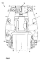
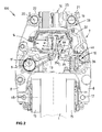
- Fig.1 and Fig.2 show a disc brake 100 for particular transversely displaceable wheelsets of rail vehicles, with an eccentrically driven brake caliper 7, the two caliper levers 6, 8 are coupled at their one ends with brake shoes 15 and in its central regions with a brake motor 14.
- the brake disc 1 is shown only partially as an axle.
- a caliper lever 6 of a brake caliper 7 are rotatably coupled about a rotational axis in a to be regarded as fixed space to be seen coupling point 10.
- the other-side caliper lever 8 is rotatably coupled in a coupling point 10 by means of a bolt 9 on the brake housing 2, the pin 9 is rotatably mounted about a rotational axis of the caliper lever 6 parallel axis of rotation on the brake housing 2 and carries eccentric axis-parallel pin extensions 11, on which the caliper lever. 8 is stored.
- a pivot arm 12 At the end of the piston rod of a brake cylinder is articulated as a force output member 13 of a brake motor 14.
- the two caliper levers 6 and 8 are rotatably coupled at their one ends with the brake disc 1 to be pressed brake shoes 15 and at their other ends with a wear adjuster 16 connecting them, in the embodiment, a push rod actuator in coupling points 17, 18, 19 and 20.
- the push rod actuator 16 and its actuator housing is provided for its coupling with each between the two cheeks 4 and 5 of the caliper levers 6 and 8 extending bearing parts 21 and 22.
- the push rod actuator 16 increases according to the wear of the brake shoes 15 its length.
- it has a control lever 24 which is rotatably mounted on the pliers lever 6 associated bearing part 21 about a longitudinal axis 25 of the push rod actuator 16.
- a pin-shaped stop portion 23 of the actuating lever 24 is by means of a bearing against the bearing member 21 restoring spring 26 in its initial position and against a in the FIGS. 3 to 8 pushed stop 37 shown.
- FIG. 3 shows, by means of a preloaded toothing 53 secured against rotation extending threaded spindle 27 coaxial with the longitudinal axis 25 rotatably and axially immovably held in the bearing part 22.
- a screwed with the threaded spindle 27 adjusting nut 31 is rotatably supported on the bearing part 21.
- the adjusting nut 31 can be coupled to the bearing part 21 via a one-way rotary coupling equipped with a wrap spring 28 or a wrap spring freewheel 29.
- the adjusting nut 31 is driven via the sleeve freewheel 38 by the adjusting lever 24 in the extension direction of the push rod actuator 16.
- wear adjuster with two one-way rotary joints or freewheels are well known and therefore need not be described in detail.
- other types of wear adjusters may be used, for example, drawbar adjusters, it is only essential that it has a control element corresponding to the adjusting lever 24.
- the threaded spindle 27 rotatably and the adjusting nut 31, however, rotatably mounted in the actuator housing 21, 22.
- the wrap spring 28 supports the torque generated by the axial force of the adjusting nut 31 directly on the actuator housing or on the bearing part 21.
- the pipe nut 31 can be rotated in the push rod actuator for wear-replaceable lengthening direction.
- an embodiment for example according to EP 0 732 247 A2 conceivable in which the threaded spindle 27 rotatably driven by the adjusting lever 24 and the adjusting nut 31 is rotatably mounted.
- Control rod 32 Between the two cheeks 4 and 5 of the caliper lever 6 runs a Control rod 32, the rounded, rear end rests in a bearing cup at the free end of the control lever 24.
- the control rod 32 is thus coupled via a coupling point 33 with the actuating lever 24, in Fig.2
- the actuating lever 24 is not shown.
- the control rod 32 In its central region, the control rod 32 is cranked to the brake caliper outside to avoid collisions with other components, in particular the brake motor 14.
- the front, also rounded end of the control rod 32 is located in a not visible here bearing cup of a rotary lever 35, as it is known from Fig.2 is apparent.
- the two-armed rotary lever 35 is rotatably mounted in its central region in a pivot point 36 and has a free leg 35a. The operation of the rotary lever 35 in connection with adjacent components is in EP 0 732 247 A2 explained in detail.
- the free end 35a of the rotary lever 35 is for forming a Tothub worn 44, as shown Fig.2 seen, brake disk side with a distance s a lever member 45 opposite.
- the lever part 45 is formed as an extension of the rotary arm 12.
- the distance s corresponds to the path which, starting from a disc brake released with a correct release stroke, covers the end of the lever part 45 when the two brake shoes 15 are still applied to the brake disk 1 without any application of the tensioning force.
- the caliper levers may be hinged centrally on a Switzerlandstangensteller 16 on the brake caliper, which can be actuated by a lever 24 in the shortening of the Glasstangenstellers.
- the wear adjuster 16 may be of any type, it only needs - as already mentioned - have a lever.
- the holder of the brake caliper on a space-fixed part, ultimately a vehicle or bogie frame, can be done at a coupling point other than the coupling point 10, the design of a Brernszangenü may possibly account for the brake housing.
- the application of the brake caliper 7 can be done differently, in one of the many known types, for example by means of a directly or via a lever mechanism with the gun levers 6, 8 coupled brake cylinder.
- the length of the push rod actuator is therefore adjustable depending on the stroke of the brake motor via a control mechanism which acts with a control rod 32 on the adjusting lever 24 of the push rod actuator 16.
- the lever 24 is mounted with a sleeve freewheel 38 in the actuator housing or bearing part 21 of the push rod actuator 16 and in a non-adjusting initial position with the pin-like stopper portion 23 against a stop 37 of the bearing part 21 and a cover 21a of the bearing part 21 by the return spring 26th loaded.
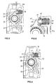
- Figure 4 in which the adjusting lever 24 is in its spring-loaded initial position.
- the stop 37 for the actuator 24 located in its initial position includes at least one elastic in the stop direction element 39, preferably a compression spring.
- the compression spring 39 is biased, wherein its biasing force is greater than the force of the adjusting lever 24 against the stop 37 loading return spring 26.
- the compression spring 39 is positioned so that the adjusting lever 24 comes to rest on it when it is rotated by the force of the return spring 26 to its original position. Since the biasing force of the prestressed compression spring 39 is greater than the force of the return spring 26, a defined starting position of the control lever 24 is ensured.
- the compression spring 39 is received in an example cylindrical recess 40 of the bearing part 21 and its lid 21 a of the push rod actuator 16 and biased there supported by two ends, wherein the compression spring 39 contacts the actuating lever 24 via a pressure piece 41, which in the recess 40th displaceable in the stop direction is stored as best Figure 4 and Figure 6 demonstrate.
- the pressure piece 41 is prevented, for example, by a snap ring 42 inserted into a radially inner annular groove of the recess 40 in the cover 21a at the exit from the recess 40 or thereby the bias of the compression spring 39 is generated.
- the pressure piece 41 biases axially through the prestressed compression spring 39 against a stop formed in the recess 40, which is formed here by the snap ring 42. Based on Figure 4 is easily conceivable that due to the lid 21a, the compression spring 39, the pressure piece 41 and the return spring 26 are easy to install.
- the return spring 26, here preferably a conical spring therefore holds the lever 24 in its initial position.
- the adjusting lever 24 rests against the pressure piece 41, which is displaceably mounted in the bearing part 21 in the recess 40 configured, for example, as a blind hole, and which can be displaced against the pretensioned compression spring 39.
- the compression spring 39 is suppressed as Fig.5 and Fig.6 demonstrate.
- the moment acting on the adjusting lever 24 and thus on the sleeve freewheel 38 is then limited to the moment or the force which is introduced by the compression spring 39 into the sleeve freewheel 38.
- the pressure piece 41 is then at elastic deformation of the compression spring 39 as in Figure 6 shown, a piece in the recess or blind hole 40 into it and lifts off from the snap ring 42, which otherwise forms the axial stop for the pressure piece 42 in the starting position.
- the wrap spring 29 leaves due to elastic strain under load a certain rotation of the pipe nut 31 in the shortening direction, so the lever 24 can follow this rotation against the force of the compression spring, the pressure piece 41 shifts linearly (see Fig. 6 ).
- the sleeve freewheel 38 is only with the moment loaded, which results from the spring force of the compression spring 39 and the distance of its line of action from the axis of rotation of the adjusting nut 31, which is coaxial with the longitudinal axis 25.
- the elastic element instead of being designed as a compression spring 39 as any elastic element.
- an embodiment as a conical spring, as with the actuator housing or bearing part 21 vulcanized or separately arranged or stored elastomer conceivable.
- an embodiment of the elastic element is also conceivable as a section integral with the bearing part 21, which due to a special geometric configuration has a higher elasticity than the areas of the bearing part 21 adjoining it. In this case, therefore, the higher flexibility or elasticity does not arise from a lower material rigidity but from a geometrically lower stiffness of the stopper 37 compared to the adjacent areas of the bearing part 21 ago.
Landscapes
- Engineering & Computer Science (AREA)
- General Engineering & Computer Science (AREA)
- Mechanical Engineering (AREA)
- Braking Arrangements (AREA)
Claims (10)
- Frein (100) à disque d'un véhicule ferroviaire, comprenant un étrier (7) de frein, dont les leviers (6, 8) sont couplés à l'une de leurs extrémités à des mâchoires (15) de frein et de l'autre côté à un dispositif (16) de rattrapage d'usure, la longueur du dispositif (16) de rattrapage d'usure étant, en fonction de la course d'un moteur (14) de force de freinage, réglable par un mécanisme de commande, qui agit par une barre (32) de commande sur un élément (24) de réglage du dispositif (16) de rattrapage d'usure, l'élément (24) de réglage étant monté par une roue libre (38) dans un boîtier (21) du dispositif (16) de rattrapage d'usure et étant, dans une position de départ sans rattrapage, appliqué par une partie (23) de butée par au moins un élément (26) de ressort de rappel sur une butée (37) du boîtier (21), caractérisé en ce que la butée (37) comporte au moins un élément (39) élastique dans la direction de butée.
- Frein à disque suivant la revendication 1, caractérisé en ce que le au moins un élément (39) élastique est précontraint, la force précontrainte de l'élément (39) élastique étant plus grande que la force du au moins un élément (26) de ressort de rappel, appliquant l'élément (24) de réglage sur la butée (37) .
- Frein à disque suivant la revendication 2, caractérisé en ce que le au moins un élément (39) élastique est déformé élastiquement, lorsque la force agissant sur celui-ci par l'élément (24) de réglage est plus grande qu'une force limite donnée à l'avance et en ce que sinon il n'y a sensiblement pas de déformation élastique de l'élément (39) élastique.
- Frein à disque suivant la revendication 2 ou 3, caractérisé en ce que l'élément (39) élastique est formé par au moins un ressort de compression précontraint.
- Frein à disque suivant la revendication 4, caractérisé en ce que le au moins un ressort (39) de compression est logé dans un évidement (40) du boîtier (21) du dispositif (16) de rattrapage d'usure et y est appuyé en étant précontraint par les deux extrémités, le au moins un ressort (39) de compression entrant en contact avec l'élément (24) de réglage par une pièce (41) d'application d'une pression, qui est montée coulissante dans l'évidement (40).
- Frein à disque suivant l'une des revendications précédentes, caractérisé en ce que le au moins un élément (39) élastique est maintenu à l'intérieur d'une vis (51) creuse, qui est vissée de l'extérieur dans un trou (52) traversant du boîtier (21).
- Frein à disque suivant l'une des revendications précédentes, caractérisé en ce que l'élément (24) de réglage prend la position de départ sans rattrapage dans une position desserrée du frein ou dans une position de serrage du frein, s'il n'y a pas de besoin de rattrapage par le dispositif (16) de rattrapage d'usure.
- Frein à disque suivant l'une des revendications précédentes, caractérisé en ce que l'élément (26) de ressort de rappel comporte au moins un ressort de compression.
- Frein à disque suivant la revendication 8, caractérisé en ce que le au moins un ressort (26) de compression est formé par un ressort conique.
- Frein à disque suivant l'une des revendications précédentes, caractérisé en ce qu'il est formé sur le boîtier (21) une autre butée (43) pour l'élément (24) de réglage, contre laquelle l'élément (24) de réglage bute par une autre partie (49) de butée, lorsque le dispositif (16) de rattrapage de l'usure rattrape un trajet de rattrapage maximum.
Applications Claiming Priority (2)
| Application Number | Priority Date | Filing Date | Title |
|---|---|---|---|
| DE102010006748 | 2010-02-02 | ||
| PCT/EP2011/051099 WO2011095424A2 (fr) | 2010-02-02 | 2011-01-27 | Actionneur à tige de pression pour des unités d'étrier de frein compactes avec levier d'actionnement se déplaçant en butée contre une butée élastique |
Publications (2)
| Publication Number | Publication Date |
|---|---|
| EP2531742A2 EP2531742A2 (fr) | 2012-12-12 |
| EP2531742B1 true EP2531742B1 (fr) | 2014-12-03 |
Family
ID=44259986
Family Applications (1)
| Application Number | Title | Priority Date | Filing Date |
|---|---|---|---|
| EP11701998.4A Not-in-force EP2531742B1 (fr) | 2010-02-02 | 2011-01-27 | Actionneur à tige de pression pour des unités d'étrier de frein compactes avec levier d'actionnement se déplaçant en butée contre une butée élastique |
Country Status (8)
| Country | Link |
|---|---|
| US (1) | US8763765B2 (fr) |
| EP (1) | EP2531742B1 (fr) |
| JP (1) | JP5864442B2 (fr) |
| KR (1) | KR101512221B1 (fr) |
| CN (1) | CN102753853B (fr) |
| DE (1) | DE102011009540A1 (fr) |
| RU (1) | RU2547942C2 (fr) |
| WO (1) | WO2011095424A2 (fr) |
Families Citing this family (16)
| Publication number | Priority date | Publication date | Assignee | Title |
|---|---|---|---|---|
| JP5880003B2 (ja) * | 2011-12-14 | 2016-03-08 | 新日鐵住金株式会社 | 鉄道車両用キャリパブレーキ装置 |
| WO2014203848A1 (fr) * | 2013-06-19 | 2014-12-24 | 新日鐵住金株式会社 | Dispositif de frein à mâchoires pour véhicule de chemin de fer |
| DE102014006291B3 (de) * | 2014-04-26 | 2015-09-03 | Audi Ag | Rotationsdämpfer |
| JP6295167B2 (ja) * | 2014-08-18 | 2018-03-14 | Kyb株式会社 | ブレーキ装置 |
| CN104260748B (zh) * | 2014-10-20 | 2017-06-13 | 青岛思锐科技有限公司 | 轨道机车车辆制动夹钳单元闸片间隙调整器 |
| CN104405799B (zh) * | 2014-11-18 | 2017-01-11 | 眉山中车制动科技股份有限公司 | 一种夹钳制动机构 |
| JP6543149B2 (ja) * | 2015-09-25 | 2019-07-10 | Kyb株式会社 | ブレーキ装置 |
| DE102015219058B3 (de) * | 2015-09-29 | 2017-04-13 | Kes Keschwari Electronic Systems Gmbh & Co. Kg | Bremszylinder mit integriertem Verschleißnachsteller für Schienenfahrzeuge |
| CN108253050B (zh) * | 2018-01-25 | 2019-05-21 | 西北工业大学 | 一种旋转机械定位锁定机构 |
| DE102019101342B4 (de) * | 2019-01-18 | 2020-07-30 | Knorr-Bremse Systeme für Schienenfahrzeuge GmbH | Verschleißnachsteller einer Kompakt-Bremszangeneinheit, und Kompakt-Bremszangeneinheit mit einem solchen Verschleißnachsteller |
| US11306787B2 (en) * | 2020-03-27 | 2022-04-19 | Chang Hui Lin | Mechanical multi-rod disc brake |
| JP7469141B2 (ja) | 2020-05-26 | 2024-04-16 | ナブテスコ株式会社 | ブレーキ装置及びブレーキ装置用の隙間調整機構 |
| JP7444757B2 (ja) * | 2020-10-28 | 2024-03-06 | ナブテスコ株式会社 | ブレーキキャリパ装置 |
| CN114215866B (zh) * | 2022-01-14 | 2025-08-08 | 中车戚墅堰机车车辆工艺研究所股份有限公司 | 一种紧凑式制动夹钳单元壳体 |
| CN115158392B (zh) * | 2022-06-10 | 2023-07-11 | 杭州申昊科技股份有限公司 | 一种基于轨道探伤车驱动装置的复位机构 |
| DE102022208094A1 (de) * | 2022-08-03 | 2024-02-08 | Knorr-Bremse Systeme für Schienenfahrzeuge GmbH | Nachstellermodul für eine Bremszange einer Fahrzeugbremse, Fahrzeugbremse mit einem solchen Nachstellermodul und Verfahren zum Notlösen des Nachstellermoduls |
Family Cites Families (17)
| Publication number | Priority date | Publication date | Assignee | Title |
|---|---|---|---|---|
| US4018140A (en) * | 1974-06-17 | 1977-04-19 | General Signal Corporation | Hydraulic disc brake actuator |
| JPS54138964A (en) * | 1978-04-20 | 1979-10-27 | Akebono Brake Ind Co Ltd | Improvements in brake assembling part for brake motor |
| DE3309265A1 (de) * | 1983-03-15 | 1984-09-20 | Knorr-Bremse GmbH, 8000 München | Selbsttaetige, sofortwirkende nachstellvorrichtung fuer den anlegehub von bremsgestaengen von insbesondere schienenfahrzeugen |
| JP2560597Y2 (ja) * | 1992-12-28 | 1998-01-26 | 山九株式会社 | ラチェットホイール回転装置 |
| RU2044668C1 (ru) * | 1993-04-02 | 1995-09-27 | Олег Олегович Вейтцель | Дисковый тормоз скоростного подвижного состава |
| DE4330440A1 (de) * | 1993-09-08 | 1995-03-09 | Knorr Bremse Ag | Krafterzeugungseinrichtung zum Erzeugen eines reversiblen Arbeitshubs |
| DE4431353C1 (de) * | 1994-09-02 | 1996-03-28 | Knorr Bremse Systeme | Bremszangeneinheit für Scheibenbremsen von Fahrzeugen, insbesondere Schienenfahrzeugen |
| DE4431321C2 (de) | 1994-09-02 | 2000-02-24 | Knorr Bremse Systeme | Bremsgestänge für Fahrzeuge, insbesondere Schienenfahrzeuge |
| DE19509540C1 (de) | 1995-03-16 | 1996-10-02 | Knorr Bremse Systeme | Scheibenbremse für Schienenfahrzeuge |
| DE19945701A1 (de) * | 1999-09-23 | 2001-04-19 | Knorr Bremse Systeme | Bremsaktuator |
| DE10214671B4 (de) | 2002-04-03 | 2006-08-24 | Knorr-Bremse Systeme für Schienenfahrzeuge GmbH | Bremszuspanneinrichtung mit elektrisch betätigter Verschleißnachstell- und Not- und Hilfslöseeinrichtung |
| DE10214669B4 (de) * | 2002-04-03 | 2014-01-23 | Knorr-Bremse Systeme für Schienenfahrzeuge GmbH | Verfahren und Vorrichtung zur Ansteuerung einer elektrisch betätigten Verschleißnachstelleinrichtung |
| DE10214670B4 (de) * | 2002-04-03 | 2014-01-23 | Knorr-Bremse Systeme für Schienenfahrzeuge GmbH | Bremszuspanneinrichtung mit elektrisch betätigtem Verschleißnachsteller |
| CN100455840C (zh) * | 2004-04-07 | 2009-01-28 | 马德拉斯机器制造私人有限公司 | 用于调整车辆制动系统的制动衬片和制动鼓之间间隙的制动间隙自动调整器 |
| CN101374636A (zh) | 2006-04-07 | 2009-02-25 | 罗腾贝格尔股份有限公司 | 钳子 |
| JP2009162289A (ja) * | 2008-01-04 | 2009-07-23 | Akebono Brake Ind Co Ltd | ディスクブレーキ装置 |
| CN101216083B (zh) * | 2008-01-14 | 2010-09-08 | 玉环凯凌集团有限公司 | 一种带驻车制动的制动钳 |
-
2011
- 2011-01-27 CN CN201180008045.8A patent/CN102753853B/zh not_active Expired - Fee Related
- 2011-01-27 EP EP11701998.4A patent/EP2531742B1/fr not_active Not-in-force
- 2011-01-27 DE DE102011009540A patent/DE102011009540A1/de not_active Ceased
- 2011-01-27 KR KR1020127022905A patent/KR101512221B1/ko not_active Expired - Fee Related
- 2011-01-27 US US13/576,716 patent/US8763765B2/en not_active Expired - Fee Related
- 2011-01-27 WO PCT/EP2011/051099 patent/WO2011095424A2/fr not_active Ceased
- 2011-01-27 RU RU2012137297/11A patent/RU2547942C2/ru not_active IP Right Cessation
- 2011-01-27 JP JP2012551579A patent/JP5864442B2/ja not_active Expired - Fee Related
Also Published As
| Publication number | Publication date |
|---|---|
| CN102753853B (zh) | 2015-05-13 |
| WO2011095424A2 (fr) | 2011-08-11 |
| HK1177779A1 (en) | 2013-08-30 |
| KR20120117917A (ko) | 2012-10-24 |
| US20120305343A1 (en) | 2012-12-06 |
| RU2012137297A (ru) | 2014-03-10 |
| EP2531742A2 (fr) | 2012-12-12 |
| CN102753853A (zh) | 2012-10-24 |
| JP2013519049A (ja) | 2013-05-23 |
| KR101512221B1 (ko) | 2015-04-14 |
| DE102011009540A1 (de) | 2011-08-04 |
| US8763765B2 (en) | 2014-07-01 |
| WO2011095424A3 (fr) | 2011-10-13 |
| JP5864442B2 (ja) | 2016-02-17 |
| RU2547942C2 (ru) | 2015-04-10 |
Similar Documents
| Publication | Publication Date | Title |
|---|---|---|
| EP2531742B1 (fr) | Actionneur à tige de pression pour des unités d'étrier de frein compactes avec levier d'actionnement se déplaçant en butée contre une butée élastique | |
| EP2531741B1 (fr) | Actionneur à tige de pression pour des unités d'étrier de frein compactes avec élément fileté prenant appui directement sur le boîtier d'actionneur | |
| EP3107779B1 (fr) | Frein de véhicule automobile, en particulier frein de véhicule automobile actionnable hydrauliquement et électromécaniquement de manière combinée, avec broche à plusieurs étages | |
| EP2682635B1 (fr) | Mécanisme d'actionnement de frein pour frein à disque | |
| EP0132601B1 (fr) | Tringlerie pour freins à friction de véhicules | |
| EP2307756A1 (fr) | Dispositif de rattrapage de jeu pour un frein à disque | |
| DE102014113826B4 (de) | Nachstelleinrichtung einer Scheibenbremse, und eine entsprechende Scheibenbremse | |
| EP0188710B1 (fr) | Tringlerie pour freins de véhicules | |
| DE102014017438A1 (de) | Scheibenbremse. insbesondere für Nutzfahrzeuge | |
| EP3102845A1 (fr) | Frein à disque de véhicule | |
| DE102014017430A1 (de) | Scheibenbremse, insbesondere für Nutzfahrzeuge | |
| EP1494909B1 (fr) | Dispositif de serrage de frein dote d'un mecanisme a commande electrique pour le reglage en fonction de l'usure | |
| DE202010003739U1 (de) | Scheibenbremse | |
| DE2362283A1 (de) | Spielnachstell-vorrichtung | |
| WO2016037934A1 (fr) | Dispositif de rattrapage de jeu pour frein à disque actionné par levier rotatif, et frein à disque pourvu d'un dispositif de rattrapage de jeu | |
| DE2261843C3 (de) | Selbsttätige, doppeltwirkende Bremsgestängenachstelleinrichtung im Bremsgestänge, insbesondere von Schienenfahrzeugen | |
| DE102017114664B4 (de) | Federspeicherbremszylinder mit einer Notlöseeinrichtung | |
| DE202010003732U1 (de) | Scheibenbremse | |
| WO2014154565A1 (fr) | Système de rattrapage de jeu destiné à un frein à disque, et frein à disque correspondant | |
| DE202010003738U1 (de) | Scheibenbremse | |
| DE10214671A1 (de) | Bremszuspanneinrichtung mit elektrisch betätigter Verschleißnachstell- und Not- und Hilfslöseeinrichtung | |
| DE202013009442U1 (de) | Verschleißnachstellvorrichtung für Scheibenbremsen | |
| DE2428645C3 (de) | Spielnachstell-Einrichtung für ein Betätigungsgestänge einer Bremse oder Kupplung für Schienenfahrzeuge | |
| DE202004009839U1 (de) | Verstellantrieb | |
| EP3867544B1 (fr) | Frein à disque |
Legal Events
| Date | Code | Title | Description |
|---|---|---|---|
| PUAI | Public reference made under article 153(3) epc to a published international application that has entered the european phase |
Free format text: ORIGINAL CODE: 0009012 |
|
| 17P | Request for examination filed |
Effective date: 20120903 |
|
| AK | Designated contracting states |
Kind code of ref document: A2 Designated state(s): AL AT BE BG CH CY CZ DE DK EE ES FI FR GB GR HR HU IE IS IT LI LT LU LV MC MK MT NL NO PL PT RO RS SE SI SK SM TR |
|
| RIN1 | Information on inventor provided before grant (corrected) |
Inventor name: RODRIGUEZ, DIEGO Inventor name: EBNER, CHRISTIAN Inventor name: LEHNEIS, MICHAEL |
|
| DAX | Request for extension of the european patent (deleted) | ||
| GRAP | Despatch of communication of intention to grant a patent |
Free format text: ORIGINAL CODE: EPIDOSNIGR1 |
|
| INTG | Intention to grant announced |
Effective date: 20140729 |
|
| GRAS | Grant fee paid |
Free format text: ORIGINAL CODE: EPIDOSNIGR3 |
|
| GRAA | (expected) grant |
Free format text: ORIGINAL CODE: 0009210 |
|
| AK | Designated contracting states |
Kind code of ref document: B1 Designated state(s): AL AT BE BG CH CY CZ DE DK EE ES FI FR GB GR HR HU IE IS IT LI LT LU LV MC MK MT NL NO PL PT RO RS SE SI SK SM TR |
|
| REG | Reference to a national code |
Ref country code: GB Ref legal event code: FG4D Free format text: NOT ENGLISH |
|
| REG | Reference to a national code |
Ref country code: CH Ref legal event code: EP Ref country code: AT Ref legal event code: REF Ref document number: 699546 Country of ref document: AT Kind code of ref document: T Effective date: 20141215 |
|
| REG | Reference to a national code |
Ref country code: IE Ref legal event code: FG4D Free format text: LANGUAGE OF EP DOCUMENT: GERMAN |
|
| REG | Reference to a national code |
Ref country code: DE Ref legal event code: R096 Ref document number: 502011005151 Country of ref document: DE Effective date: 20150122 |
|
| REG | Reference to a national code |
Ref country code: SE Ref legal event code: TRGR |
|
| REG | Reference to a national code |
Ref country code: NL Ref legal event code: VDEP Effective date: 20141203 |
|
| PG25 | Lapsed in a contracting state [announced via postgrant information from national office to epo] |
Ref country code: NO Free format text: LAPSE BECAUSE OF FAILURE TO SUBMIT A TRANSLATION OF THE DESCRIPTION OR TO PAY THE FEE WITHIN THE PRESCRIBED TIME-LIMIT Effective date: 20150303 Ref country code: LT Free format text: LAPSE BECAUSE OF FAILURE TO SUBMIT A TRANSLATION OF THE DESCRIPTION OR TO PAY THE FEE WITHIN THE PRESCRIBED TIME-LIMIT Effective date: 20141203 Ref country code: NL Free format text: LAPSE BECAUSE OF FAILURE TO SUBMIT A TRANSLATION OF THE DESCRIPTION OR TO PAY THE FEE WITHIN THE PRESCRIBED TIME-LIMIT Effective date: 20141203 Ref country code: FI Free format text: LAPSE BECAUSE OF FAILURE TO SUBMIT A TRANSLATION OF THE DESCRIPTION OR TO PAY THE FEE WITHIN THE PRESCRIBED TIME-LIMIT Effective date: 20141203 Ref country code: ES Free format text: LAPSE BECAUSE OF FAILURE TO SUBMIT A TRANSLATION OF THE DESCRIPTION OR TO PAY THE FEE WITHIN THE PRESCRIBED TIME-LIMIT Effective date: 20141203 |
|
| REG | Reference to a national code |
Ref country code: LT Ref legal event code: MG4D |
|
| PG25 | Lapsed in a contracting state [announced via postgrant information from national office to epo] |
Ref country code: HR Free format text: LAPSE BECAUSE OF FAILURE TO SUBMIT A TRANSLATION OF THE DESCRIPTION OR TO PAY THE FEE WITHIN THE PRESCRIBED TIME-LIMIT Effective date: 20141203 Ref country code: CY Free format text: LAPSE BECAUSE OF FAILURE TO SUBMIT A TRANSLATION OF THE DESCRIPTION OR TO PAY THE FEE WITHIN THE PRESCRIBED TIME-LIMIT Effective date: 20141203 Ref country code: RS Free format text: LAPSE BECAUSE OF FAILURE TO SUBMIT A TRANSLATION OF THE DESCRIPTION OR TO PAY THE FEE WITHIN THE PRESCRIBED TIME-LIMIT Effective date: 20141203 Ref country code: GR Free format text: LAPSE BECAUSE OF FAILURE TO SUBMIT A TRANSLATION OF THE DESCRIPTION OR TO PAY THE FEE WITHIN THE PRESCRIBED TIME-LIMIT Effective date: 20150304 Ref country code: LV Free format text: LAPSE BECAUSE OF FAILURE TO SUBMIT A TRANSLATION OF THE DESCRIPTION OR TO PAY THE FEE WITHIN THE PRESCRIBED TIME-LIMIT Effective date: 20141203 |
|
| PG25 | Lapsed in a contracting state [announced via postgrant information from national office to epo] |
Ref country code: CZ Free format text: LAPSE BECAUSE OF FAILURE TO SUBMIT A TRANSLATION OF THE DESCRIPTION OR TO PAY THE FEE WITHIN THE PRESCRIBED TIME-LIMIT Effective date: 20141203 Ref country code: RO Free format text: LAPSE BECAUSE OF FAILURE TO SUBMIT A TRANSLATION OF THE DESCRIPTION OR TO PAY THE FEE WITHIN THE PRESCRIBED TIME-LIMIT Effective date: 20141203 Ref country code: EE Free format text: LAPSE BECAUSE OF FAILURE TO SUBMIT A TRANSLATION OF THE DESCRIPTION OR TO PAY THE FEE WITHIN THE PRESCRIBED TIME-LIMIT Effective date: 20141203 Ref country code: PT Free format text: LAPSE BECAUSE OF FAILURE TO SUBMIT A TRANSLATION OF THE DESCRIPTION OR TO PAY THE FEE WITHIN THE PRESCRIBED TIME-LIMIT Effective date: 20150403 Ref country code: SK Free format text: LAPSE BECAUSE OF FAILURE TO SUBMIT A TRANSLATION OF THE DESCRIPTION OR TO PAY THE FEE WITHIN THE PRESCRIBED TIME-LIMIT Effective date: 20141203 |
|
| REG | Reference to a national code |
Ref country code: CH Ref legal event code: PL |
|
| PG25 | Lapsed in a contracting state [announced via postgrant information from national office to epo] |
Ref country code: IS Free format text: LAPSE BECAUSE OF FAILURE TO SUBMIT A TRANSLATION OF THE DESCRIPTION OR TO PAY THE FEE WITHIN THE PRESCRIBED TIME-LIMIT Effective date: 20150403 Ref country code: LU Free format text: LAPSE BECAUSE OF FAILURE TO SUBMIT A TRANSLATION OF THE DESCRIPTION OR TO PAY THE FEE WITHIN THE PRESCRIBED TIME-LIMIT Effective date: 20150127 Ref country code: PL Free format text: LAPSE BECAUSE OF FAILURE TO SUBMIT A TRANSLATION OF THE DESCRIPTION OR TO PAY THE FEE WITHIN THE PRESCRIBED TIME-LIMIT Effective date: 20141203 |
|
| REG | Reference to a national code |
Ref country code: DE Ref legal event code: R097 Ref document number: 502011005151 Country of ref document: DE |
|
| PG25 | Lapsed in a contracting state [announced via postgrant information from national office to epo] |
Ref country code: MC Free format text: LAPSE BECAUSE OF FAILURE TO SUBMIT A TRANSLATION OF THE DESCRIPTION OR TO PAY THE FEE WITHIN THE PRESCRIBED TIME-LIMIT Effective date: 20141203 |
|
| PLBE | No opposition filed within time limit |
Free format text: ORIGINAL CODE: 0009261 |
|
| STAA | Information on the status of an ep patent application or granted ep patent |
Free format text: STATUS: NO OPPOSITION FILED WITHIN TIME LIMIT |
|
| PG25 | Lapsed in a contracting state [announced via postgrant information from national office to epo] |
Ref country code: CH Free format text: LAPSE BECAUSE OF NON-PAYMENT OF DUE FEES Effective date: 20150131 Ref country code: DK Free format text: LAPSE BECAUSE OF FAILURE TO SUBMIT A TRANSLATION OF THE DESCRIPTION OR TO PAY THE FEE WITHIN THE PRESCRIBED TIME-LIMIT Effective date: 20141203 Ref country code: LI Free format text: LAPSE BECAUSE OF NON-PAYMENT OF DUE FEES Effective date: 20150131 |
|
| REG | Reference to a national code |
Ref country code: IE Ref legal event code: MM4A |
|
| 26N | No opposition filed |
Effective date: 20150904 |
|
| GBPC | Gb: european patent ceased through non-payment of renewal fee |
Effective date: 20150303 |
|
| REG | Reference to a national code |
Ref country code: FR Ref legal event code: PLFP Year of fee payment: 6 |
|
| PG25 | Lapsed in a contracting state [announced via postgrant information from national office to epo] |
Ref country code: GB Free format text: LAPSE BECAUSE OF NON-PAYMENT OF DUE FEES Effective date: 20150303 Ref country code: IE Free format text: LAPSE BECAUSE OF NON-PAYMENT OF DUE FEES Effective date: 20150127 |
|
| PG25 | Lapsed in a contracting state [announced via postgrant information from national office to epo] |
Ref country code: SI Free format text: LAPSE BECAUSE OF FAILURE TO SUBMIT A TRANSLATION OF THE DESCRIPTION OR TO PAY THE FEE WITHIN THE PRESCRIBED TIME-LIMIT Effective date: 20141203 |
|
| PGFP | Annual fee paid to national office [announced via postgrant information from national office to epo] |
Ref country code: IT Payment date: 20160122 Year of fee payment: 6 Ref country code: DE Payment date: 20160119 Year of fee payment: 6 Ref country code: TR Payment date: 20160120 Year of fee payment: 6 |
|
| PGFP | Annual fee paid to national office [announced via postgrant information from national office to epo] |
Ref country code: FR Payment date: 20160121 Year of fee payment: 6 Ref country code: SE Payment date: 20160121 Year of fee payment: 6 |
|
| PG25 | Lapsed in a contracting state [announced via postgrant information from national office to epo] |
Ref country code: MT Free format text: LAPSE BECAUSE OF FAILURE TO SUBMIT A TRANSLATION OF THE DESCRIPTION OR TO PAY THE FEE WITHIN THE PRESCRIBED TIME-LIMIT Effective date: 20141203 |
|
| REG | Reference to a national code |
Ref country code: AT Ref legal event code: MM01 Ref document number: 699546 Country of ref document: AT Kind code of ref document: T Effective date: 20160127 |
|
| PG25 | Lapsed in a contracting state [announced via postgrant information from national office to epo] |
Ref country code: SM Free format text: LAPSE BECAUSE OF FAILURE TO SUBMIT A TRANSLATION OF THE DESCRIPTION OR TO PAY THE FEE WITHIN THE PRESCRIBED TIME-LIMIT Effective date: 20141203 Ref country code: BG Free format text: LAPSE BECAUSE OF FAILURE TO SUBMIT A TRANSLATION OF THE DESCRIPTION OR TO PAY THE FEE WITHIN THE PRESCRIBED TIME-LIMIT Effective date: 20141203 Ref country code: AT Free format text: LAPSE BECAUSE OF NON-PAYMENT OF DUE FEES Effective date: 20160127 Ref country code: HU Free format text: LAPSE BECAUSE OF FAILURE TO SUBMIT A TRANSLATION OF THE DESCRIPTION OR TO PAY THE FEE WITHIN THE PRESCRIBED TIME-LIMIT; INVALID AB INITIO Effective date: 20110127 |
|
| PG25 | Lapsed in a contracting state [announced via postgrant information from national office to epo] |
Ref country code: BE Free format text: LAPSE BECAUSE OF NON-PAYMENT OF DUE FEES Effective date: 20150131 |
|
| REG | Reference to a national code |
Ref country code: DE Ref legal event code: R119 Ref document number: 502011005151 Country of ref document: DE |
|
| REG | Reference to a national code |
Ref country code: FR Ref legal event code: ST Effective date: 20170929 |
|
| PG25 | Lapsed in a contracting state [announced via postgrant information from national office to epo] |
Ref country code: FR Free format text: LAPSE BECAUSE OF NON-PAYMENT OF DUE FEES Effective date: 20170131 |
|
| PG25 | Lapsed in a contracting state [announced via postgrant information from national office to epo] |
Ref country code: SE Free format text: LAPSE BECAUSE OF NON-PAYMENT OF DUE FEES Effective date: 20170128 Ref country code: DE Free format text: LAPSE BECAUSE OF NON-PAYMENT OF DUE FEES Effective date: 20170801 |
|
| PG25 | Lapsed in a contracting state [announced via postgrant information from national office to epo] |
Ref country code: IT Free format text: LAPSE BECAUSE OF NON-PAYMENT OF DUE FEES Effective date: 20170127 |
|
| PG25 | Lapsed in a contracting state [announced via postgrant information from national office to epo] |
Ref country code: MK Free format text: LAPSE BECAUSE OF FAILURE TO SUBMIT A TRANSLATION OF THE DESCRIPTION OR TO PAY THE FEE WITHIN THE PRESCRIBED TIME-LIMIT Effective date: 20141203 |
|
| PG25 | Lapsed in a contracting state [announced via postgrant information from national office to epo] |
Ref country code: AL Free format text: LAPSE BECAUSE OF FAILURE TO SUBMIT A TRANSLATION OF THE DESCRIPTION OR TO PAY THE FEE WITHIN THE PRESCRIBED TIME-LIMIT Effective date: 20141203 |
|
| PG25 | Lapsed in a contracting state [announced via postgrant information from national office to epo] |
Ref country code: TR Free format text: LAPSE BECAUSE OF NON-PAYMENT OF DUE FEES Effective date: 20170127 |