EP2531874B1 - Adaptive linse - Google Patents
Adaptive linse Download PDFInfo
- Publication number
- EP2531874B1 EP2531874B1 EP11701074.4A EP11701074A EP2531874B1 EP 2531874 B1 EP2531874 B1 EP 2531874B1 EP 11701074 A EP11701074 A EP 11701074A EP 2531874 B1 EP2531874 B1 EP 2531874B1
- Authority
- EP
- European Patent Office
- Prior art keywords
- lens
- chamber
- lens surfaces
- pressure
- adaptive
- Prior art date
- Legal status (The legal status is an assumption and is not a legal conclusion. Google has not performed a legal analysis and makes no representation as to the accuracy of the status listed.)
- Active
Links
Images
Classifications
-
- G—PHYSICS
- G02—OPTICS
- G02B—OPTICAL ELEMENTS, SYSTEMS OR APPARATUS
- G02B26/00—Optical devices or arrangements for the control of light using movable or deformable optical elements
- G02B26/08—Optical devices or arrangements for the control of light using movable or deformable optical elements for controlling the direction of light
- G02B26/0875—Optical devices or arrangements for the control of light using movable or deformable optical elements for controlling the direction of light by means of one or more refracting elements
-
- B—PERFORMING OPERATIONS; TRANSPORTING
- B23—MACHINE TOOLS; METAL-WORKING NOT OTHERWISE PROVIDED FOR
- B23K—SOLDERING OR UNSOLDERING; WELDING; CLADDING OR PLATING BY SOLDERING OR WELDING; CUTTING BY APPLYING HEAT LOCALLY, e.g. FLAME CUTTING; WORKING BY LASER BEAM
- B23K26/00—Working by laser beam, e.g. welding, cutting or boring
- B23K26/02—Positioning or observing the workpiece, e.g. with respect to the point of impact; Aligning, aiming or focusing the laser beam
- B23K26/04—Automatically aligning, aiming or focusing the laser beam, e.g. using the back-scattered light
- B23K26/046—Automatically focusing the laser beam
-
- G—PHYSICS
- G02—OPTICS
- G02B—OPTICAL ELEMENTS, SYSTEMS OR APPARATUS
- G02B3/00—Simple or compound lenses
- G02B3/12—Fluid-filled or evacuated lenses
- G02B3/14—Fluid-filled or evacuated lenses of variable focal length
Definitions
- the present invention relates to an adaptive lens for laser material processing, in particular in the high-power range of at least approx. 1 kW, according to the preamble of claim 1.
- YAG lasers are already known, with which corrections of the focal position and beam diameter of a laser beam can be carried out in real time, for example to enable controlled laser processing on workpieces.
- the adaptive mirror has a deformable mirror plate, which is deformed quickly and in a targeted manner, for example by a piezo actuator, so that the focal length of the adaptive mirror can be continuously regulated.
- the mirror plates are available with a highly reflective coating for CO 2 lasers (10.6 ⁇ m) or for Nd: YAG lasers (1.06 ⁇ m).
- both ring actuators are each arranged on the outside of the lens surfaces facing away from the chamber.
- the lens surfaces are formed by two membranes which are each pulled together or apart radially by the two ring-shaped electrodes and are firmly clamped at the edges.
- one or both actuators are operated. In order to achieve either a concave or a convex curvature of both lens surfaces, both actuators must always be used "against each other".
- US 2008/0316610 A1 discloses an adaptive lens having a fluid-filled chamber, two non-deformable end plates, and one disposed in the chamber Lens surface in the form of a meniscus membrane, which can be moved back and forth by means of a piezoelectric ring actuator in order to change the curvature of the lens surface due to the pressure difference that occurs.
- an adaptive lens in which an annular piston causes a change in volume in the chamber, the resulting negative or positive pressure leading to a change in the curvature of the lens.
- the chamber is formed by a dumbbell-shaped membrane and the annular piston acts on the two thicker outer areas of the dumbbell-shaped membrane.
- the chamber volume enclosed between the two lens surfaces is filled with a fluid that is (optically) transparent to the laser radiation.
- a fluid that is (optically) transparent to the laser radiation.
- the chamber with the fluid is connected to a pressure compensation element (e.g. a pressure compensation tank) so that low-frequency changes in volume and pressure are compensated and the focus position remains stable.
- a pressure compensation element e.g. a pressure compensation tank
- active pressure control can also be carried out via the pressure equalization tank by means of activation. This can be used to specify the shaping of the lens surfaces at low frequency or statically. If no high-frequency focus oscillations are sought, the focus position can be adjusted here.
- a mean focus position of the laser beam on the workpiece can be set by means of a mean fluid pressure, around which the focus position oscillates if necessary.
- the lens surfaces are designed as plane-parallel plates, which are elastically deformed when there is overpressure or underpressure in the chamber and without pressure - quasi in their "rest position" - no (or only slight) influence on the beam guidance and shaping of the Take the laser beam.
- the Lens surfaces are involved in beam shaping from the outset, i.e. already in the non-pressurized state, through appropriate contouring.
- the lens surfaces are formed from glass.
- the adaptive lens according to the invention is particularly suitable for the fundamental wavelengths of solid-state lasers, that is to say wavelengths in the range of approximately 1 ⁇ m.
- the adaptive lens is also suitable for harmonics of these fundamental wavelengths (frequency conversion).
- the lens surfaces each have, on their (outer) side facing away from the chamber and / or on their (inner) side facing the chamber, a particularly different coating that maximizes the transmission at the transition of the respective media to one another.
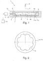
- the adaptive lens 1 shown serves to adapt and vary the focal position of a laser beam 2, in particular during laser material processing in the high-power range of at least approximately 1 kW.
- the adaptive lens 1 comprises two deformable lens surfaces 4a, 4b spaced from one another in the direction of the optical axis 3 , a chamber 5 which is formed between the two lens surfaces 4a, 4b and which is filled with a fluid 6 (e.g. based on silicone oil) that is transparent to the laser radiation, and a device 7 for changing the distance between the two lens surfaces 4a, 4b from one another along the optical axis 3.
- the two lens surfaces 4a, 4b are made of a material transparent to the laser radiation, in particular glass, with a damage threshold adapted to the laser power and can, for example, be plane-parallel Be plates.
- the two lens surfaces 4a, 4b and an intermediate ring 8 arranged between them are axially clamped at the edge between two ring shoulders 9 of a housing (ring mount) 10 and are sealed against one another by means of seals (not shown).
- the chamber 5 is thus defined by the two lens surfaces 4 and the intermediate ring 8.
- the device 7 for changing the distance between the two lens surfaces 4a, 4b has two piezoelectric ring actuators 11a, 11b which act in the axial direction and which are located on both sides of the in FIG Fig. 1 lower lens surface 4b are provided and their axial length increases in each case in the case of their activation.
- the in Fig. 1 The upper ring actuator 11a is arranged inside the chamber 5 on the inside of the lower lens surface 4b facing the chamber 5 and is supported on an annular shoulder of the intermediate ring 8, while the lower ring actuator 11b is arranged on the outer side of the lower lens surface 4b facing away from the chamber 5 and on a ring shoulder of the housing 10 is supported.
- the lower lens surface 4b can be axially outward relative to the upper lens surface 4a (in Fig. 1 downward), and by controlling the lower ring actuator 11b, the lower lens surface 4b can be moved axially inward relative to the upper lens surface 4a (in Fig. 1 up) are moved or deflected.
- the local distance from the upper lens surface 4a and thus the volume available to the fluid 6 changes in this area.
- a pressure change in the fluid causes a deformation of the two lens surfaces 4a, 4b symmetrical to the optical axis 3.
- a reduction in the pressure does not necessarily result in a concave deformation, since, for example, only a previously made convex curvature is reduced.
- a concave deformation only occurs when a negative pressure is reached or when the stress conditions result.
- the ring actuators 11a, 11b each have radially inwardly projecting projections 12 with which the lower lens surface 4b is each axially deflected.
- the chamber 5 with the fluid 6 is connected via a feed line 13 to a pressure compensation element 14, as is known to the person skilled in the art from a large number of applications.
- the pressure compensation element 14 can for example be a pressure compensation container which has two chambers separated by a membrane, one of which is filled with a gas and the other contains a liquid.
- the liquid-filled chamber is connected via the feed line 13 to the chamber 5 formed by the lens surfaces 4a, 4b and the intermediate ring 8, so that due to the longer reaction time in the pressure compensation tank for pressure build-up and pressure reduction, low-frequency changes in volume and pressure are compensated and the focus position remains stable .
- the pressure equalization element 14 is activated via a controller 15 , so that the pressure in the chamber 5 and thus the curvature of the lens surfaces 4a, 4b can be actively adjusted via this.
- This allows a position of rest to be defined or, proceeding from this, further changes in the focus position can be made, which can be understood as starting or central positions. These can then be superimposed with high-frequency focus position oscillations via appropriate actuators.
- one or two ring actuators can also be arranged on the upper lens surface 4a.
- the two lens surfaces 4a, 4b can have a different coating on their outside facing away from the chamber 5 and / or on their inside facing the chamber 5, which increases the transmission at the transition of the respective media, such as air to glass, glass to fluid, fluid Glass and glass to air, maximized to one another.
Landscapes
- Physics & Mathematics (AREA)
- Optics & Photonics (AREA)
- Engineering & Computer Science (AREA)
- General Physics & Mathematics (AREA)
- Plasma & Fusion (AREA)
- Mechanical Engineering (AREA)
- Mechanical Light Control Or Optical Switches (AREA)
Description
- Die vorliegende Erfindung betrifft eine adaptive Linse für die Lasermaterialbearbeitung, insbesondere im Hochleistungsbereich von mindestens ca. 1 kW, gemäß dem Oberbegriff von Anspruch 1.
- Eine derartige adaptive Linse ist beispielsweise durch die
US 2008/225379 A1 bekannt geworden. - Es sind bereits adaptive Optiken in Form von adaptiven Spiegeln für CO2- oder Nd:YAG-Laser bekannt, mit denen sich in Echtzeit Korrekturen von Fokuslage und Strahldurchmesser eines Laserstrahls durchführen lassen, um z.B. eine kontrollierte Laserbearbeitung auf Werkstücken zu ermöglichen. Der adaptive Spiegel weist eine deformierbare Spiegelplatte auf, die z.B. von einem Piezo-Aktuator schnell und gezielt verformt wird, so dass sich die Brennweite des adaptiven Spiegels stufenlos regeln lässt. Die Spiegelplatten sind mit einer hochreflektiven Beschichtung für CO2-Laser (10,6 µm) oder für Nd:YAG-Laser (1,06 µm) erhältlich.
- Bei der aus
US 2008/0225379 A1 bekannten adaptiven Linse sind beide Ringaktuatoren jeweils an der der Kammer abgewandten Außenseite der Linsenflächen angeordnet. Die Linsenflächen sind durch zwei Membrane gebildet, die durch die beiden ringförmigen Elektroden jeweils radial zusammen- oder auseinandergezogen werden und randseitig fest eingespannt sind. Um eine Verformung der adaptiven Linse zu erreichen, werden einer oder beide Aktuatoren betätigt. Um wahlweise eine konkave oder eine konvexe Krümmung beider Linsenflächen zu erreichen, müssen stets beide Aktuatoren "gegeneinander" eingesetzt werden. -
US 2008/0316610 A1 offenbart eine adaptive Linse mit einer fluidgefüllten Kammer, mit zwei nicht verformbaren Endplatten und mit einer in der Kammer angeordneten Linsenfläche in Form einer Meniskusmembran, die mittels eines piezoelektrischen Ringaktuators vor- und zurückbewegbar ist, um durch den dabei auftretenden Druckunterschied die Wölbung der Linsenfläche zu verändern. - Schließlich ist aus
US 2009/0052049 A1 eine adaptive Linse bekannt, bei der durch einen ringförmigen Kolben eine Volumenänderung in der Kammer bewirkt wird, wobei der dadurch entstehende Unter- oder Überdruck zu einer Änderung der Linsenkrümmung führt. Die Kammer ist durch eine hantelförmige Membran gebildet, und der ringförmige Kolben wirkt auf die beiden dickeren Außenbereiche der hantelförmigen Membran. - Demgegenüber ist es die Aufgabe der vorliegenden Erfindung, bei einer adaptiven Linse der eingangs genannten Art eine alternative Einrichtung zum elastischen Verformen der beiden Linsenflächen anzugeben.
- Diese Aufgabe wird erfindungsgemäß durch eine adaptive Linse mit den Merkmalen von Anspruch 1 gelöst.
- Das zwischen den beiden Linsenflächen eingeschlossene Kammervolumen wird durch ein für die Laserstrahlung (optisch) transparentes Fluid ausgefüllt. Durch Bewegen zumindest einer der beiden Linsenflächen relativ zur anderen Linsenfläche ändert sich lokal an den bewegten Bereichen der Abstand und somit das dem Fluid zur Verfügung stehende Volumen. Hierdurch erhöht sich im Falle einer Verringerung des lokalen Abstands der beiden Linsenflächen der Druck des Fluids auf die Linsenflächen, wodurch diese sich elastisch verformen. Im beschriebenen Fall der Druckerhöhung bilden die Linsenflächen eine konvexe Kontur aus, wodurch der durch die adaptive Linse hindurchtretende Laserstrahl eine Veränderung seiner Fokuslage erfährt. Sind die beiden Linsenflächen randseitig symmetrisch zur optischen Achse eingespannt, so wird die Druckänderung im Fluid symmetrisch zur optischen Achse auf die Linsenflächen eingebracht. Durch die zwei Ringaktuatoren kann in der Kammer wahlweise ein Über- oder Unterdruck und somit wahlweise eine konvexe oder konkave Wölbung der beiden Linsenflächen bewirkt werden.
- Zur Kompensation von thermisch bedingten Wärmeausdehnungen ist die Kammer mit dem Fluid an ein Druckausgleichselement (z.B. einen Druckausgleichsbehälter) angeschlossen, so dass niederfrequente Volumen- und Druckänderungen ausgeglichen werden und die Fokuslage stabil bleibt. Neben dem eigentlichen Druckausgleich, der passiv erfolgt, kann über den Druckausgleichsbehälter mittels Ansteuerung auch eine aktive Drucksteuerung vorgenommen werden. Diese kann dazu genutzt werden, die Formung der Linsenflächen niederfrequent bzw. statisch vorzugeben. Werden keine hochfrequenten Fokusoszillationen angestrebt, kann die Fokuslage hierüber eingestellt werden.
- Hochfrequente, durch oszillierende Bewegungen der Einrichtung zur Änderung des Abstands der beiden Linsenflächen hervorgerufene Volumenänderungen führen zu einer hochfrequenten Fokusoszillation. Desweiteren kann durch einen mittleren Fluiddruck eine mittlere Fokuslage des Laserstrahls am Werkstück eingestellt werden, um die herum bei Bedarf die Fokuslage oszilliert.
- In einer bevorzugten Ausführungsform sind die Linsenflächen als planparallele Platten ausgebildet, die bei einem in der Kammer herrschenden Über- oder Unterdruck elastisch verformt werden und ohne Druckbeaufschlagung - quasi in ihrer "Ruhelage" - keinen (oder nur geringen) Einfluss auf die Strahlführung und Formung des Laserstrahls nehmen. In einer alternativen Ausführungsform sind die Linsenflächen durch eine entsprechende Konturgebung von vorneherein, also bereits im nicht-druckbeaufschlagten Zustand, an der Strahlformung beteiligt.
- Erfindungsgemäß sind die Linsenflächen aus Glas gebildet.
- Die erfindungsgemäße adaptive Linse eignet sich insbesondere für die Grundwellenlängen von Festkörperlasern, also Wellenlängen im Bereich von ca. 1 µm. Darüber hinaus eignet sich die adaptive Linse auch für Harmonische dieser Grundwellenlängen (Frequenzkonversion).
- In einer weiteren bevorzugten Ausführungsform weisen die Linsenflächen jeweils auf ihrer der Kammer abgewandten (Außen-)Seite und/oder auf ihrer der Kammer zugewandten (Innen-)Seite eine insbesondere unterschiedliche Beschichtung auf, die die Transmission am Übergang der jeweiligen Medien zueinander maximiert. Weitere Vorteile der Erfindung ergeben sich aus den Ansprüchen, der Beschreibung und der Zeichnung. Ebenso können die vorstehend genannten und die noch weiter aufgeführten Merkmale je für sich oder zu mehreren in beliebigen Kombinationen Verwendung finden. Die gezeigten und beschriebenen Ausführungsformen sind nicht als abschließende Aufzählung zu verstehen, sondern haben vielmehr beispielhaften Charakter für die Schilderung der Erfindung.
- Es zeigen:
- Fig. 1
- einen Längsschnitt durch die erfindungsgemäße adaptive Linse; und
- Fig. 2
- eine Draufsicht auf einen piezoelektrischen Ringaktuator von
Fig. 1 . - Die in
Fig. 1 gezeigte adaptive Linse 1 dient zur Anpassung und Variation der Fokuslage eines Laserstrahls 2, und zwar insbesondere bei der Lasermaterialbearbeitung im Hochleistungsbereich von mindestens ca. 1 kW. - Die adaptive Linse 1 umfasst zwei voneinander in Richtung der optischen Achse 3 beabstandete, verformbare Linsenflächen 4a, 4b, eine zwischen den beiden Linsenflächen 4a, 4b ausgebildete Kammer 5, die mit einem für die Laserstrahlung transparenten Fluid 6 (z.B. auf Silikonölbasis) gefüllt ist, sowie eine Einrichtung 7 zur Änderung des Abstands der beiden Linsenflächen 4a, 4b zueinander entlang der optischen Achse 3. Die beiden Linsenflächen 4a, 4b sind aus einem für die Laserstrahlung transparenten Material, insbesondere aus Glas, mit einer der Laserleistung angepassten Zerstörschwelle und können beispielsweise planparallele Platten sein.
- Die beiden Linsenflächen 4a, 4b und ein dazwischen angeordneter Zwischenring 8 sind randseitig zwischen zwei Ringabsätzen 9 eines Gehäuses (Ringfassung) 10 axial eingespannt und dabei über nicht gezeigte Dichtungen gegeneinander abgedichtet. Die Kammer 5 ist also durch die beiden Linsenflächen 4 und den Zwischenring 8 definiert.
- Die Einrichtung 7 zur Abstandsänderung der beiden Linsenflächen 4a, 4b weist zwei in axialer Richtung wirkende piezoelektrische Ringaktuatoren 11a, 11b auf, die an beiden Seiten der in
Fig. 1 unteren Linsenfläche 4b vorgesehen sind und deren axiale Länge sich im Falle ihrer Ansteuerung jeweils vergrößert. Der inFig. 1 obere Ringaktuator 11a ist innerhalb der Kammer 5 an der der Kammer 5 zugewandten Innenseite der unteren Linsenfläche 4b angeordnet und an einem Ringabsatz des Zwischenrings 8 abgestützt, während der untere Ringaktuator 11b an der der Kammer 5 abgewandten Außenseite der unteren Linsenfläche 4b angeordnet und an einem Ringabsatz des Gehäuses 10 abgestützt ist. - Durch Ansteuerung des oberen Ringaktuators 11a kann die untere Linsenfläche 4b randseitig relativ zur oberen Linsenfläche 4a axial nach außen (in
Fig. 1 nach unten) bewegt bzw. ausgelenkt werden, und durch Ansteuerung des unteren Ringaktuators 11b kann die untere Linsenfläche 4b relativ zur oberen Linsenfläche 4a axial nach innen (inFig. 1 nach oben) bewegt bzw. ausgelenkt werden. Durch diese lokale Bewegung bzw. Auslenkung der unteren Linsenfläche 4b ändert sich in diesem Bereich jeweils der lokale Abstand zur oberen Linsenfläche 4a und somit das dem Fluid 6 zur Verfügung stehende Volumen. Hierdurch erhöht sich im Falle einer Verringerung des lokalen Abstands der beiden Linsenflächen 4a, 4b der Druck des Fluids auf die Linsenflächen 4a, 4b, wodurch diese sich elastisch nach außen verformen und jeweils eine konvexe Linsenkontur ausbilden. Im Falle einer Vergrößerung des lokalen Abstands der beiden Linsenflächen 4a, 4b verringert sich der Druck des Fluids auf die Linsenflächen 4a, 4b, wodurch diese sich elastisch nach innen verformen und jeweils eine konkave Linsenkontur ausbilden. In beiden Fällen erfährt der durch die adaptive Linse 1 hindurchtretende Laserstrahl 7 eine Veränderung seiner Fokuslage. Da die beiden Linsenflächen 4a, 4b und die Ringaktuatoren 11a, 11b symmetrisch zur optischen Achse 3 eingespannt sind, bewirkt eine Druckänderung im Fluid eine zur optischen Achse 3 symmetrische Verformung der beiden Linsenflächen 4a, 4b. Eine Verringerung des Drucks resultiert nicht zwingend in einer konkaven Verformung, da bspw. auch nur eine zuvor erfolgte konvexe Wölbung reduziert wird. Erst mit Erreichen eines Unterdrucks stellt sich eine konkave Verformung ein bzw. wenn die Spannungsverhältnisse dies ergeben. - Wie in
Fig. 2 gezeigt, weisen die Ringaktuatoren 11a, 11b jeweils radial nach innen vorspringende Vorsprünge 12 auf, mit denen die untere Linsenfläche 4b jeweils axial ausgelenkt wird. - Zur Kompensation von thermisch bedingten Wärmeausdehnungen ist die Kammer 5 mit dem Fluid 6 über eine Zuleitung 13 an ein Druckausgleichselement 14, wie es dem Fachmann aus einer Vielzahl von Anwendungen bekannt ist, angeschlossen. Das Druckausgleichselement 14 kann beispielsweise ein Druckausgleichsbehälter sein, der zwei durch eine Membran getrennte Kammern aufweist, von denen die eine mit einem Gas gefüllt ist und die andere eine Flüssigkeit enthält. Die flüssigkeitsgefüllte Kammer ist über die Zuleitung 13 an die durch die Linsenflächen 4a, 4b und den Zwischenring 8 gebildete Kammer 5 angeschlossen, so dass aufgrund der im Druckausgleichsbehälter für Druckaufbau und -abbau längeren Reaktionszeit niederfrequente Volumen- und Druckänderungen ausgeglichen werden und die Fokuslage stabil bleibt.
- Zudem wird das Druckausgleichselement 14 über eine Steuerung 15 angesteuert, so dass der Druck in der Kammer 5 und somit die Wölbung der Linsenflächen 4a, 4b hierüber aktiv eingestellt werden können. Hierdurch können eine Ruhelage definiert bzw. von dieser ausgehend weitere Fokuslagenänderungen vorgenommen werden, die als Ausgangs- oder Mittellagen verstanden werden können. Diese können dann über entsprechende Aktuatoren mit hochfrequenten Fokuslagenoszillationen überlagert werden.
- Zusätzlich oder alternativ können ein oder zwei Ringaktuatoren auch an der oberen Linsenfläche 4a angeordnet sein.
- Weiterhin können die beiden Linsenflächen 4a, 4b auf ihrer der Kammer 5 abgewandten Außenseite und/oder auf ihrer der Kammer 5 zugewandten Innenseite eine unterschiedliche Beschichtung aufweisen, die die Transmission am Übergang der jeweiligen Medien, wie Luft zu Glas, Glas zu Fluid, Fluid zu Glas und Glas zu Luft, zueinander maximiert.
Claims (4)
- Adaptive Linse (1) für die Lasermaterialbearbeitung, insbesondere im Hochleistungsbereich von mindestens ca. 1 kW, umfassend:zwei voneinander in Richtung der optischen Achse (3) beabstandete,verformbare Linsenflächen (4a, 4b),eine zwischen den beiden Linsenflächen (4a, 4b) ausgebildete Kammer (5),die mit einem Fluid (6) gefüllt ist, undeine Einrichtung (7) mit mindestens zwei piezoelektrischen Ringaktuatoren (11a, 11b) zum elastischen Verformen der beiden Linsenflächen (4a, 4b) entweder jeweils axial nach innen oder jeweils axial nach außen, wobei der eine piezoelektrische Ringaktuator (11b) an einer der Kammer (5) abgewandten Außenseite einer der beiden Linsenflächen (4a, 4b) angeordnet ist,dadurch gekennzeichnet,dass die Linsenflächen durch zwei Glasplatten (4a, 4b) gebildet sind, und dass der andere piezoelektrische Ringaktuator (11a) an einer der Kammer (5) zugewandten Innenseite einer der beiden Glasplatten (4a, 4b) angeordnet ist.
- Adaptive Linse nach Anspruch 1, dadurch gekennzeichnet, dass die Kammer (5) mit dem Fluid (6) an ein Druckausgleichselement (14) angeschlossen ist.
- Adaptive Linse nach Anspruch 2, dadurch gekennzeichnet, dass das Druckausgleichselement (14) zum Druckausgleich von niederfrequenten Druckänderungen ausgebildet ist.
- Adaptive Linse nach einem der vorhergehenden Ansprüche, dadurch gekennzeichnet, dass die Glasplatten (4a, 4b) jeweils durch plane oder gekrümmte Glasplatten gebildet sind.
Priority Applications (1)
| Application Number | Priority Date | Filing Date | Title |
|---|---|---|---|
| PL11701074T PL2531874T3 (pl) | 2010-02-03 | 2011-01-19 | Soczewka adaptacyjna |
Applications Claiming Priority (2)
| Application Number | Priority Date | Filing Date | Title |
|---|---|---|---|
| DE102010001551A DE102010001551A1 (de) | 2010-02-03 | 2010-02-03 | Adaptive Linse |
| PCT/EP2011/050672 WO2011095395A1 (de) | 2010-02-03 | 2011-01-19 | Adaptive linse |
Publications (2)
| Publication Number | Publication Date |
|---|---|
| EP2531874A1 EP2531874A1 (de) | 2012-12-12 |
| EP2531874B1 true EP2531874B1 (de) | 2020-10-14 |
Family
ID=43589755
Family Applications (1)
| Application Number | Title | Priority Date | Filing Date |
|---|---|---|---|
| EP11701074.4A Active EP2531874B1 (de) | 2010-02-03 | 2011-01-19 | Adaptive linse |
Country Status (6)
| Country | Link |
|---|---|
| US (1) | US8649103B2 (de) |
| EP (1) | EP2531874B1 (de) |
| CN (1) | CN102792192B (de) |
| DE (1) | DE102010001551A1 (de) |
| PL (1) | PL2531874T3 (de) |
| WO (1) | WO2011095395A1 (de) |
Families Citing this family (11)
| Publication number | Priority date | Publication date | Assignee | Title |
|---|---|---|---|---|
| FR3015699B1 (fr) * | 2013-12-20 | 2016-02-05 | Wavelens | Dispositif optique pour stabilisation d'images |
| CN105223710A (zh) * | 2015-10-16 | 2016-01-06 | 深圳市创鑫激光股份有限公司 | 一种光隔离器、激光输出头及激光设备 |
| US11895931B2 (en) | 2017-11-28 | 2024-02-06 | International Business Machines Corporation | Frequency tuning of multi-qubit systems |
| US10355193B2 (en) | 2017-11-28 | 2019-07-16 | International Business Machines Corporation | Flip chip integration on qubit chips |
| US10170681B1 (en) | 2017-11-28 | 2019-01-01 | International Business Machines Corporation | Laser annealing of qubits with structured illumination |
| US10418540B2 (en) | 2017-11-28 | 2019-09-17 | International Business Machines Corporation | Adjustment of qubit frequency through annealing |
| CN109975898A (zh) | 2017-12-27 | 2019-07-05 | 华为技术有限公司 | 一种镜头模组和镜头模组的控制方法 |
| CN112276346B (zh) * | 2020-10-22 | 2021-11-09 | 温州大学 | 一种超高功率激光切割自动精准调焦加工头 |
| CN114192972B (zh) * | 2021-12-07 | 2023-09-19 | 潍坊新松机器人自动化有限公司 | 型材表面焊前处理装置 |
| DE102022116699A1 (de) * | 2022-07-05 | 2024-01-11 | Carl Zeiss Smt Gmbh | Optisches Element und Projektionsbelichtungsanlage für die Halbleiterlithographie |
| EP4575307A3 (de) * | 2023-11-28 | 2025-08-20 | Harman Professional Denmark ApS | Systeme für mehrlinsenvorrichtungen |
Citations (2)
| Publication number | Priority date | Publication date | Assignee | Title |
|---|---|---|---|---|
| US20080225379A1 (en) * | 2001-11-09 | 2008-09-18 | The Charles Stark Draper Laboratory, Inc. | High speed piezoelectric optical system with tunable focal length |
| US20080316610A1 (en) * | 2005-12-16 | 2008-12-25 | Koninklijke Philips Electronics, N.V. | Piezoelectric Variable Focus Fluid Lens and Method of Focusing |
Family Cites Families (11)
| Publication number | Priority date | Publication date | Assignee | Title |
|---|---|---|---|---|
| JPH0675102A (ja) * | 1992-08-28 | 1994-03-18 | Canon Inc | 光学素子 |
| JPH0949904A (ja) * | 1995-08-07 | 1997-02-18 | Toshiba Corp | レーザ装置用光学レンズ及びレーザ装置 |
| JP4078575B2 (ja) * | 1998-06-26 | 2008-04-23 | 株式会社デンソー | 可変焦点レンズ装置 |
| US7646544B2 (en) * | 2005-05-14 | 2010-01-12 | Batchko Robert G | Fluidic optical devices |
| EP1567903B1 (de) * | 2002-10-25 | 2010-09-01 | Koninklijke Philips Electronics N.V. | Zoomlinse |
| GB0407414D0 (en) * | 2004-04-01 | 2004-05-05 | 1 Ltd | Variable focal length lens |
| GB2422206A (en) * | 2005-01-13 | 2006-07-19 | Exitech Ltd | Optical device with controlled variation of working angle for laser micromachining operation |
| JP5069232B2 (ja) * | 2005-07-25 | 2012-11-07 | カール・ツァイス・エスエムティー・ゲーエムベーハー | マイクロリソグラフィ投影露光装置の投影対物レンズ |
| JP2007222902A (ja) * | 2006-02-23 | 2007-09-06 | Seiko Epson Corp | レーザ加工装置及びレーザ加工方法 |
| EP1837696B1 (de) * | 2006-03-20 | 2016-10-12 | WaveLight GmbH | Optisches Abbildungssystem und Verfahren zum Steuern sowie Verwendung eines solchen |
| JP2010513952A (ja) * | 2006-12-15 | 2010-04-30 | ハンド ヘルド プロダクツ インコーポレーティッド | 変形可能なレンズ要素よりなる装置、および方法 |
-
2010
- 2010-02-03 DE DE102010001551A patent/DE102010001551A1/de not_active Withdrawn
-
2011
- 2011-01-19 WO PCT/EP2011/050672 patent/WO2011095395A1/de not_active Ceased
- 2011-01-19 CN CN201180012041.7A patent/CN102792192B/zh not_active Expired - Fee Related
- 2011-01-19 PL PL11701074T patent/PL2531874T3/pl unknown
- 2011-01-19 EP EP11701074.4A patent/EP2531874B1/de active Active
-
2012
- 2012-08-03 US US13/565,893 patent/US8649103B2/en not_active Expired - Fee Related
Patent Citations (2)
| Publication number | Priority date | Publication date | Assignee | Title |
|---|---|---|---|---|
| US20080225379A1 (en) * | 2001-11-09 | 2008-09-18 | The Charles Stark Draper Laboratory, Inc. | High speed piezoelectric optical system with tunable focal length |
| US20080316610A1 (en) * | 2005-12-16 | 2008-12-25 | Koninklijke Philips Electronics, N.V. | Piezoelectric Variable Focus Fluid Lens and Method of Focusing |
Also Published As
| Publication number | Publication date |
|---|---|
| WO2011095395A1 (de) | 2011-08-11 |
| CN102792192B (zh) | 2014-09-17 |
| CN102792192A (zh) | 2012-11-21 |
| US8649103B2 (en) | 2014-02-11 |
| PL2531874T3 (pl) | 2021-04-19 |
| US20130003188A1 (en) | 2013-01-03 |
| DE102010001551A1 (de) | 2011-08-04 |
| EP2531874A1 (de) | 2012-12-12 |
Similar Documents
| Publication | Publication Date | Title |
|---|---|---|
| WO2011095395A1 (de) | Adaptive linse | |
| DE60121352T2 (de) | Ausgleichvorrichtung mit einer flexiblen membran für ein kraftstoffeinspritzventil und verfahren dafür | |
| EP3311015B1 (de) | Längenverstellbare pleuelstange | |
| EP2035686B1 (de) | Kraftstoffinjektor | |
| EP1079098A2 (de) | Dosiervorrichtung | |
| DE102008049556A1 (de) | Mikrolithographische Projektionsbelichtungsanlage | |
| DE102007004080A1 (de) | Variables achromatisches Membranlinsensystem sowie Verfahren zum Betrieb | |
| EP1118897A2 (de) | Deformierbarer Spiegel, insbesondere für eine Laserstrahl-Materialbearbeitungseinrichtung | |
| EP0795081B1 (de) | Elektrohydraulischer antrieb | |
| EP1079099A2 (de) | Dosierventil | |
| EP2243202B1 (de) | Festkörper-laser | |
| EP0784754B1 (de) | Mikromechanischer aktor | |
| DE102013008646A1 (de) | Adaptiver Spiegel für eine Laserbearbeitungsvorrichtung | |
| DE102012212953A1 (de) | Spiegelanordnung für eine Lithographieanlage | |
| DE4236355C2 (de) | Adaptiver Membranspiegel | |
| DE102017126307A1 (de) | Dosiervorrichtung sowie Verfahren zum Dosieren von flüssigen Medien | |
| EP1424584B1 (de) | Spiegel einer Laserbearbeitungsmaschine | |
| EP1896914B1 (de) | Adaptiver spiegel einer optik einer laserbearbeitungsmaschine | |
| DE102015224495A1 (de) | Laserstrahlablenkung zur gezielten Energiedeposition | |
| DE4412948A1 (de) | Elektrohydraulische Absperrvorrichtung | |
| EP1347200A2 (de) | Hydrolager | |
| DE4137832A1 (de) | Vorrichtung zum lagern einer gesteuert deformierbaren platte geringer dicke, insbesondere eines spiegels als reflektionseinrichtung fuer laserstrahlen o. dgl. | |
| WO2020043552A1 (de) | Optisches system zur verwendung in einer unterwasserumgebung | |
| EP3342010B1 (de) | Verspannungsoptimiertes laserscheibenträgersystem | |
| DE102005047082A1 (de) | Verfahren zur Mikrostrukturierung von Oberflächen eines Werkstücks und seine Verwendung |
Legal Events
| Date | Code | Title | Description |
|---|---|---|---|
| PUAI | Public reference made under article 153(3) epc to a published international application that has entered the european phase |
Free format text: ORIGINAL CODE: 0009012 |
|
| 17P | Request for examination filed |
Effective date: 20120903 |
|
| AK | Designated contracting states |
Kind code of ref document: A1 Designated state(s): AL AT BE BG CH CY CZ DE DK EE ES FI FR GB GR HR HU IE IS IT LI LT LU LV MC MK MT NL NO PL PT RO RS SE SI SK SM TR |
|
| DAX | Request for extension of the european patent (deleted) | ||
| 17Q | First examination report despatched |
Effective date: 20140711 |
|
| STAA | Information on the status of an ep patent application or granted ep patent |
Free format text: STATUS: EXAMINATION IS IN PROGRESS |
|
| REG | Reference to a national code |
Ref country code: DE Ref legal event code: R079 Ref document number: 502011016934 Country of ref document: DE Free format text: PREVIOUS MAIN CLASS: G02B0003140000 Ipc: B23K0026046000 |
|
| GRAP | Despatch of communication of intention to grant a patent |
Free format text: ORIGINAL CODE: EPIDOSNIGR1 |
|
| STAA | Information on the status of an ep patent application or granted ep patent |
Free format text: STATUS: GRANT OF PATENT IS INTENDED |
|
| RIC1 | Information provided on ipc code assigned before grant |
Ipc: B23K 26/046 20140101AFI20200508BHEP Ipc: G02B 3/14 20060101ALI20200508BHEP Ipc: G02B 26/08 20060101ALI20200508BHEP |
|
| INTG | Intention to grant announced |
Effective date: 20200603 |
|
| GRAS | Grant fee paid |
Free format text: ORIGINAL CODE: EPIDOSNIGR3 |
|
| GRAA | (expected) grant |
Free format text: ORIGINAL CODE: 0009210 |
|
| STAA | Information on the status of an ep patent application or granted ep patent |
Free format text: STATUS: THE PATENT HAS BEEN GRANTED |
|
| AK | Designated contracting states |
Kind code of ref document: B1 Designated state(s): AL AT BE BG CH CY CZ DE DK EE ES FI FR GB GR HR HU IE IS IT LI LT LU LV MC MK MT NL NO PL PT RO RS SE SI SK SM TR |
|
| REG | Reference to a national code |
Ref country code: GB Ref legal event code: FG4D Free format text: NOT ENGLISH |
|
| REG | Reference to a national code |
Ref country code: AT Ref legal event code: REF Ref document number: 1323101 Country of ref document: AT Kind code of ref document: T Effective date: 20201015 Ref country code: CH Ref legal event code: EP |
|
| REG | Reference to a national code |
Ref country code: DE Ref legal event code: R096 Ref document number: 502011016934 Country of ref document: DE |
|
| REG | Reference to a national code |
Ref country code: IE Ref legal event code: FG4D Free format text: LANGUAGE OF EP DOCUMENT: GERMAN |
|
| REG | Reference to a national code |
Ref country code: CH Ref legal event code: NV Representative=s name: DENNEMEYER AG, CH |
|
| REG | Reference to a national code |
Ref country code: NL Ref legal event code: MP Effective date: 20201014 |
|
| PG25 | Lapsed in a contracting state [announced via postgrant information from national office to epo] |
Ref country code: RS Free format text: LAPSE BECAUSE OF FAILURE TO SUBMIT A TRANSLATION OF THE DESCRIPTION OR TO PAY THE FEE WITHIN THE PRESCRIBED TIME-LIMIT Effective date: 20201014 Ref country code: FI Free format text: LAPSE BECAUSE OF FAILURE TO SUBMIT A TRANSLATION OF THE DESCRIPTION OR TO PAY THE FEE WITHIN THE PRESCRIBED TIME-LIMIT Effective date: 20201014 Ref country code: NL Free format text: LAPSE BECAUSE OF FAILURE TO SUBMIT A TRANSLATION OF THE DESCRIPTION OR TO PAY THE FEE WITHIN THE PRESCRIBED TIME-LIMIT Effective date: 20201014 Ref country code: NO Free format text: LAPSE BECAUSE OF FAILURE TO SUBMIT A TRANSLATION OF THE DESCRIPTION OR TO PAY THE FEE WITHIN THE PRESCRIBED TIME-LIMIT Effective date: 20210114 Ref country code: PT Free format text: LAPSE BECAUSE OF FAILURE TO SUBMIT A TRANSLATION OF THE DESCRIPTION OR TO PAY THE FEE WITHIN THE PRESCRIBED TIME-LIMIT Effective date: 20210215 Ref country code: GR Free format text: LAPSE BECAUSE OF FAILURE TO SUBMIT A TRANSLATION OF THE DESCRIPTION OR TO PAY THE FEE WITHIN THE PRESCRIBED TIME-LIMIT Effective date: 20210115 |
|
| REG | Reference to a national code |
Ref country code: LT Ref legal event code: MG4D |
|
| PG25 | Lapsed in a contracting state [announced via postgrant information from national office to epo] |
Ref country code: SE Free format text: LAPSE BECAUSE OF FAILURE TO SUBMIT A TRANSLATION OF THE DESCRIPTION OR TO PAY THE FEE WITHIN THE PRESCRIBED TIME-LIMIT Effective date: 20201014 Ref country code: LV Free format text: LAPSE BECAUSE OF FAILURE TO SUBMIT A TRANSLATION OF THE DESCRIPTION OR TO PAY THE FEE WITHIN THE PRESCRIBED TIME-LIMIT Effective date: 20201014 Ref country code: ES Free format text: LAPSE BECAUSE OF FAILURE TO SUBMIT A TRANSLATION OF THE DESCRIPTION OR TO PAY THE FEE WITHIN THE PRESCRIBED TIME-LIMIT Effective date: 20201014 Ref country code: IS Free format text: LAPSE BECAUSE OF FAILURE TO SUBMIT A TRANSLATION OF THE DESCRIPTION OR TO PAY THE FEE WITHIN THE PRESCRIBED TIME-LIMIT Effective date: 20210214 Ref country code: BG Free format text: LAPSE BECAUSE OF FAILURE TO SUBMIT A TRANSLATION OF THE DESCRIPTION OR TO PAY THE FEE WITHIN THE PRESCRIBED TIME-LIMIT Effective date: 20210114 |
|
| PG25 | Lapsed in a contracting state [announced via postgrant information from national office to epo] |
Ref country code: HR Free format text: LAPSE BECAUSE OF FAILURE TO SUBMIT A TRANSLATION OF THE DESCRIPTION OR TO PAY THE FEE WITHIN THE PRESCRIBED TIME-LIMIT Effective date: 20201014 |
|
| REG | Reference to a national code |
Ref country code: DE Ref legal event code: R097 Ref document number: 502011016934 Country of ref document: DE |
|
| PG25 | Lapsed in a contracting state [announced via postgrant information from national office to epo] |
Ref country code: LT Free format text: LAPSE BECAUSE OF FAILURE TO SUBMIT A TRANSLATION OF THE DESCRIPTION OR TO PAY THE FEE WITHIN THE PRESCRIBED TIME-LIMIT Effective date: 20201014 Ref country code: RO Free format text: LAPSE BECAUSE OF FAILURE TO SUBMIT A TRANSLATION OF THE DESCRIPTION OR TO PAY THE FEE WITHIN THE PRESCRIBED TIME-LIMIT Effective date: 20201014 Ref country code: SK Free format text: LAPSE BECAUSE OF FAILURE TO SUBMIT A TRANSLATION OF THE DESCRIPTION OR TO PAY THE FEE WITHIN THE PRESCRIBED TIME-LIMIT Effective date: 20201014 Ref country code: SM Free format text: LAPSE BECAUSE OF FAILURE TO SUBMIT A TRANSLATION OF THE DESCRIPTION OR TO PAY THE FEE WITHIN THE PRESCRIBED TIME-LIMIT Effective date: 20201014 Ref country code: CZ Free format text: LAPSE BECAUSE OF FAILURE TO SUBMIT A TRANSLATION OF THE DESCRIPTION OR TO PAY THE FEE WITHIN THE PRESCRIBED TIME-LIMIT Effective date: 20201014 Ref country code: EE Free format text: LAPSE BECAUSE OF FAILURE TO SUBMIT A TRANSLATION OF THE DESCRIPTION OR TO PAY THE FEE WITHIN THE PRESCRIBED TIME-LIMIT Effective date: 20201014 |
|
| PLBE | No opposition filed within time limit |
Free format text: ORIGINAL CODE: 0009261 |
|
| STAA | Information on the status of an ep patent application or granted ep patent |
Free format text: STATUS: NO OPPOSITION FILED WITHIN TIME LIMIT |
|
| PG25 | Lapsed in a contracting state [announced via postgrant information from national office to epo] |
Ref country code: MC Free format text: LAPSE BECAUSE OF FAILURE TO SUBMIT A TRANSLATION OF THE DESCRIPTION OR TO PAY THE FEE WITHIN THE PRESCRIBED TIME-LIMIT Effective date: 20201014 Ref country code: DK Free format text: LAPSE BECAUSE OF FAILURE TO SUBMIT A TRANSLATION OF THE DESCRIPTION OR TO PAY THE FEE WITHIN THE PRESCRIBED TIME-LIMIT Effective date: 20201014 |
|
| 26N | No opposition filed |
Effective date: 20210715 |
|
| GBPC | Gb: european patent ceased through non-payment of renewal fee |
Effective date: 20210119 |
|
| PG25 | Lapsed in a contracting state [announced via postgrant information from national office to epo] |
Ref country code: LU Free format text: LAPSE BECAUSE OF NON-PAYMENT OF DUE FEES Effective date: 20210119 |
|
| REG | Reference to a national code |
Ref country code: BE Ref legal event code: MM Effective date: 20210131 |
|
| PG25 | Lapsed in a contracting state [announced via postgrant information from national office to epo] |
Ref country code: AL Free format text: LAPSE BECAUSE OF FAILURE TO SUBMIT A TRANSLATION OF THE DESCRIPTION OR TO PAY THE FEE WITHIN THE PRESCRIBED TIME-LIMIT Effective date: 20201014 |
|
| PG25 | Lapsed in a contracting state [announced via postgrant information from national office to epo] |
Ref country code: SI Free format text: LAPSE BECAUSE OF FAILURE TO SUBMIT A TRANSLATION OF THE DESCRIPTION OR TO PAY THE FEE WITHIN THE PRESCRIBED TIME-LIMIT Effective date: 20201014 Ref country code: GB Free format text: LAPSE BECAUSE OF NON-PAYMENT OF DUE FEES Effective date: 20210119 |
|
| PG25 | Lapsed in a contracting state [announced via postgrant information from national office to epo] |
Ref country code: IE Free format text: LAPSE BECAUSE OF NON-PAYMENT OF DUE FEES Effective date: 20210119 |
|
| REG | Reference to a national code |
Ref country code: AT Ref legal event code: MM01 Ref document number: 1323101 Country of ref document: AT Kind code of ref document: T Effective date: 20210119 |
|
| PG25 | Lapsed in a contracting state [announced via postgrant information from national office to epo] |
Ref country code: AT Free format text: LAPSE BECAUSE OF NON-PAYMENT OF DUE FEES Effective date: 20210119 |
|
| PG25 | Lapsed in a contracting state [announced via postgrant information from national office to epo] |
Ref country code: IS Free format text: LAPSE BECAUSE OF FAILURE TO SUBMIT A TRANSLATION OF THE DESCRIPTION OR TO PAY THE FEE WITHIN THE PRESCRIBED TIME-LIMIT Effective date: 20210214 |
|
| PG25 | Lapsed in a contracting state [announced via postgrant information from national office to epo] |
Ref country code: BE Free format text: LAPSE BECAUSE OF NON-PAYMENT OF DUE FEES Effective date: 20210131 |
|
| PGFP | Annual fee paid to national office [announced via postgrant information from national office to epo] |
Ref country code: PL Payment date: 20221228 Year of fee payment: 13 |
|
| PGFP | Annual fee paid to national office [announced via postgrant information from national office to epo] |
Ref country code: FR Payment date: 20230124 Year of fee payment: 13 Ref country code: CH Payment date: 20230119 Year of fee payment: 13 |
|
| PG25 | Lapsed in a contracting state [announced via postgrant information from national office to epo] |
Ref country code: HU Free format text: LAPSE BECAUSE OF FAILURE TO SUBMIT A TRANSLATION OF THE DESCRIPTION OR TO PAY THE FEE WITHIN THE PRESCRIBED TIME-LIMIT; INVALID AB INITIO Effective date: 20110119 Ref country code: CY Free format text: LAPSE BECAUSE OF FAILURE TO SUBMIT A TRANSLATION OF THE DESCRIPTION OR TO PAY THE FEE WITHIN THE PRESCRIBED TIME-LIMIT Effective date: 20201014 |
|
| PGFP | Annual fee paid to national office [announced via postgrant information from national office to epo] |
Ref country code: IT Payment date: 20230120 Year of fee payment: 13 Ref country code: DE Payment date: 20230123 Year of fee payment: 13 |
|
| PG25 | Lapsed in a contracting state [announced via postgrant information from national office to epo] |
Ref country code: MK Free format text: LAPSE BECAUSE OF FAILURE TO SUBMIT A TRANSLATION OF THE DESCRIPTION OR TO PAY THE FEE WITHIN THE PRESCRIBED TIME-LIMIT Effective date: 20201014 |
|
| PG25 | Lapsed in a contracting state [announced via postgrant information from national office to epo] |
Ref country code: TR Free format text: LAPSE BECAUSE OF FAILURE TO SUBMIT A TRANSLATION OF THE DESCRIPTION OR TO PAY THE FEE WITHIN THE PRESCRIBED TIME-LIMIT Effective date: 20201014 |
|
| REG | Reference to a national code |
Ref country code: DE Ref legal event code: R119 Ref document number: 502011016934 Country of ref document: DE |
|
| REG | Reference to a national code |
Ref country code: CH Ref legal event code: PL |
|
| PG25 | Lapsed in a contracting state [announced via postgrant information from national office to epo] |
Ref country code: MT Free format text: LAPSE BECAUSE OF FAILURE TO SUBMIT A TRANSLATION OF THE DESCRIPTION OR TO PAY THE FEE WITHIN THE PRESCRIBED TIME-LIMIT Effective date: 20201014 |
|
| PG25 | Lapsed in a contracting state [announced via postgrant information from national office to epo] |
Ref country code: DE Free format text: LAPSE BECAUSE OF NON-PAYMENT OF DUE FEES Effective date: 20240801 |
|
| PG25 | Lapsed in a contracting state [announced via postgrant information from national office to epo] |
Ref country code: FR Free format text: LAPSE BECAUSE OF NON-PAYMENT OF DUE FEES Effective date: 20240131 |
|
| PG25 | Lapsed in a contracting state [announced via postgrant information from national office to epo] |
Ref country code: CH Free format text: LAPSE BECAUSE OF NON-PAYMENT OF DUE FEES Effective date: 20240131 |
|
| PG25 | Lapsed in a contracting state [announced via postgrant information from national office to epo] |
Ref country code: FR Free format text: LAPSE BECAUSE OF NON-PAYMENT OF DUE FEES Effective date: 20240131 Ref country code: DE Free format text: LAPSE BECAUSE OF NON-PAYMENT OF DUE FEES Effective date: 20240801 Ref country code: CH Free format text: LAPSE BECAUSE OF NON-PAYMENT OF DUE FEES Effective date: 20240131 |
|
| PG25 | Lapsed in a contracting state [announced via postgrant information from national office to epo] |
Ref country code: IT Free format text: LAPSE BECAUSE OF NON-PAYMENT OF DUE FEES Effective date: 20240119 |
|
| PG25 | Lapsed in a contracting state [announced via postgrant information from national office to epo] |
Ref country code: PL Free format text: LAPSE BECAUSE OF NON-PAYMENT OF DUE FEES Effective date: 20240119 |