EP2532404A1 - Mécanisme de maintien à niveau pour écrans latéraux - Google Patents
Mécanisme de maintien à niveau pour écrans latéraux Download PDFInfo
- Publication number
- EP2532404A1 EP2532404A1 EP12171359A EP12171359A EP2532404A1 EP 2532404 A1 EP2532404 A1 EP 2532404A1 EP 12171359 A EP12171359 A EP 12171359A EP 12171359 A EP12171359 A EP 12171359A EP 2532404 A1 EP2532404 A1 EP 2532404A1
- Authority
- EP
- European Patent Office
- Prior art keywords
- plates
- screens
- lateral
- bars
- basin floor
- Prior art date
- Legal status (The legal status is an assumption and is not a legal conclusion. Google has not performed a legal analysis and makes no representation as to the accuracy of the status listed.)
- Withdrawn
Links
- 238000000034 method Methods 0.000 claims abstract description 26
- 238000004873 anchoring Methods 0.000 claims description 5
- XLYOFNOQVPJJNP-UHFFFAOYSA-N water Substances O XLYOFNOQVPJJNP-UHFFFAOYSA-N 0.000 description 12
- 230000000712 assembly Effects 0.000 description 8
- 238000000429 assembly Methods 0.000 description 8
- 239000004033 plastic Substances 0.000 description 6
- 229920003023 plastic Polymers 0.000 description 6
- 239000004800 polyvinyl chloride Substances 0.000 description 6
- 239000010935 stainless steel Substances 0.000 description 6
- 229910001220 stainless steel Inorganic materials 0.000 description 6
- 238000009434 installation Methods 0.000 description 5
- 239000002184 metal Substances 0.000 description 5
- 229920000915 polyvinyl chloride Polymers 0.000 description 5
- 238000005553 drilling Methods 0.000 description 4
- 239000000463 material Substances 0.000 description 4
- 239000000853 adhesive Substances 0.000 description 2
- 230000001070 adhesive effect Effects 0.000 description 2
- 238000010612 desalination reaction Methods 0.000 description 2
- 238000001914 filtration Methods 0.000 description 2
- 239000007788 liquid Substances 0.000 description 2
- 230000004048 modification Effects 0.000 description 2
- 238000012986 modification Methods 0.000 description 2
- 125000006850 spacer group Chemical group 0.000 description 2
- GPRLSGONYQIRFK-MNYXATJNSA-N triton Chemical compound [3H+] GPRLSGONYQIRFK-MNYXATJNSA-N 0.000 description 2
- 235000019687 Lamb Nutrition 0.000 description 1
- 229920000459 Nitrile rubber Polymers 0.000 description 1
- 229910045601 alloy Inorganic materials 0.000 description 1
- 239000000956 alloy Substances 0.000 description 1
- 230000004075 alteration Effects 0.000 description 1
- 230000007797 corrosion Effects 0.000 description 1
- 238000005260 corrosion Methods 0.000 description 1
- 230000001419 dependent effect Effects 0.000 description 1
- 230000000694 effects Effects 0.000 description 1
- 239000012530 fluid Substances 0.000 description 1
- 230000014759 maintenance of location Effects 0.000 description 1
- 239000007769 metal material Substances 0.000 description 1
- 239000002991 molded plastic Substances 0.000 description 1
- 150000002825 nitriles Chemical class 0.000 description 1
- 239000002245 particle Substances 0.000 description 1
- 229920001084 poly(chloroprene) Polymers 0.000 description 1
- 239000013535 sea water Substances 0.000 description 1
- 239000000126 substance Substances 0.000 description 1
- 238000003466 welding Methods 0.000 description 1
- 238000004804 winding Methods 0.000 description 1
Images







Classifications
-
- B—PERFORMING OPERATIONS; TRANSPORTING
- B01—PHYSICAL OR CHEMICAL PROCESSES OR APPARATUS IN GENERAL
- B01D—SEPARATION
- B01D24/00—Filters comprising loose filtering material, i.e. filtering material without any binder between the individual particles or fibres thereof
- B01D24/02—Filters comprising loose filtering material, i.e. filtering material without any binder between the individual particles or fibres thereof with the filter bed stationary during the filtration
- B01D24/20—Filters comprising loose filtering material, i.e. filtering material without any binder between the individual particles or fibres thereof with the filter bed stationary during the filtration the filtering material being provided in an open container
- B01D24/22—Downward filtration, the filter material being supported by pervious surfaces
Definitions
- a backwash mode can be used clean the media. In the backwash mode, water and air are directed upwardly through the screen and media bed in a uniform manner so that the material previously filtered out and captured by the media bed can be discharged through an overflow trough.
- the underdrain system is formed of stainless steel and has its screen portion situated between two up-turned, side edge portions of its elongated flat base plate. Its screen portion is formed by helically winding and welding a metal wire to a channel base support as described in Geske U.S. Pat. No. 4,096,911 , for example.
- Screens and base plates that form lateral assemblies for underdrain systems can be quite large, often measuring as long as 30 feet, but they are more typically about 20 feet long.
- such lateral assemblies as described above have been formed of metal. Accordingly, these assemblies are difficult to transport and assemble due to their weight.
- these metal assemblies are to be used with seawater or brackish water, they are subject to corrosion even when fabricated of stainless steel.
- the base plates of these metal assemblies are usually relatively thin, allowing them to bow during use unless a substantial number of fixtures are provided to keep them in place and flat against the basin floor.
- the lateral screen 10 has a curved screen element 20 and a rigid extruded base plate 50.
- the lateral screens 10 can be similar to the lateral screens of Johnson Screen's Triton® Underdrain System.
- This screen 10 can be used in water treatment applications. When installed at the bottom of a water treatment basin, the lateral screen 10 collects and distributes water while directly retaining filtering media.
- the base plate 50 has a central opening 54 for a fitting seal 55 composed of nitrile or neoprene rubber, and the lateral screen 10 can be closed at its ends by molded plastic end caps 80. When installed in a basin, the fitting seal 55 fits onto the end of a drop pipe (not shown) passing through the floor of the basin.
- the screen element 20 slides into channels 52 along the longitudinal edges of the base plate 50, which is composed of extruded polyvinylchloride (PVC).
- the screen element 20 is composed of PVC wire 40 (e.g., Vee-Wire®) wound around and welded to "U" shaped channel rods 30 at each intersection to the channel ribs 34.
- VEE-WIRE is a registered U.S. trademark of Weatherford/Lamb, Inc.
- the screen element 20 can also be made of other materials, such as stainless steel or as required by the process in which the screen will be used.
- the wires 40 and ribs 30 define small openings for the retention of media and collection of filtered liquid. During fluid flow, the small openings cooperate with each other to form a flow distribution system for uniformly controlling the flow of water and air passing into and out of the screen element 20.
- the underdrain screen 10 it is desirable for the underdrain screen 10 to have an extended length.
- a longer screen 10 needs additional leveling and hold down capability due to higher variations in the flatness of the basin floor in the larger basins the longer screens 10 will be installed. Typically, this will be for larger water treatment or desalination plants.
- the variation on the floor height of the basin is typically specified to be within 1/4". This has allowed the underdrain screens 10 to be successfully installed and used without the need for sophisticated leveling. For larger basins, however, it can be difficult to maintain the 1/4" tolerance in flatness. In some cases, shims or other spacer systems must be placed under the underdrain screens 10 by installers.
- Stainless steel underdrain screens can have a leveling screw welded to the side of the screens to allow them to be leveled for larger basins.
- the tops of these leveling screws are held down by a channel, which both holds the underdrain screens in place and prevents the leveling screws from moving during operation. This form of leveling and hold down is not available for screens made of plastic, such as PVC.
- the common way of leveling and retaining underdrain lateral screens 10 of plastic in a basin B uses shims 70 and upper hold-down bars 60. Operators fit the shims 70 underneath the screens 10 where needed along their length to level them. To hold down the screens 10, operators install the angle hold-down bars 60 over the top of the lateral screens 10. These bars 60 affix by anchor bolts 65 in the basin floor and run perpendicular to the length of the lateral screens 10.
- the subject matter of the present disclosure is directed to overcoming, or at least reducing the effects of, one or more of the problems set forth above.
- the apparatus may comprise a plurality of plates having opposing ends. Each of the opposing ends may have at least one threaded opening.
- the plates may fit between the lateral screens and a basin floor with the threaded openings exposed along longitudinal sides of the lateral screens.
- the apparatus may comprise a plurality of adjustment bolts threaded in the threaded openings of the plates and adjusting the level of the plates relative to the basin floor.
- the apparatus may comprise a plurality of bars disposing between adjoining ends of the plates on adjacent ones of the lateral screens. The bars may engage the adjoining ends of the plates and the longitudinal sides of the adjacent ones of the lateral screens, the bars anchoring to the basin floor.
- the apparatus may comprise a leveling hold-down apparatus for lateral screens on a basin floor.
- the plates may comprise first plates each having inner and outer ends for the opposing ends. Each of the first plates may have two of the threaded openings on the outer end and may have one of the threaded openings on the inner end.
- the bars may comprise first bars each defining an opening fitting on an anchor affixed to the basin floor. An end of the first bar may engage the end of one of the first plates and the longitudinal side of one of the lateral screens.
- each first bar may dispose in a cutaway on the outer end of the first plate between the two threaded openings.
- the plates may comprise second plates each having a first of the threaded openings on one of the ends and may have a second of the threaded openings on the other end.
- the first and second threaded openings may be disposed on opposite sides of an axis of the second plate.
- the bars may comprise second bars each defining an opening fitting on an anchor affixed to the basin floor. Opposing ends of the second bar may engage the ends of the adjoining plates and the longitudinal sides of the adjacent lateral screens.
- each second bar may dispose in cutaways on the ends of the second plates between the threaded openings.
- Each of the plates may comprise a bottom having upturned rims on the opposing ends of the bottom.
- the threaded openings may comprise nuts affixed to the upturned rims.
- an underdrain system for a basin floor may comprise a plurality of lateral screens disposing parallel to one another on the basin floor.
- the system may comprise a plurality of plates having opposing ends. Each of the opposing ends may have at least one threaded opening.
- the plates may fit between the lateral screens and the basin floor with the threaded openings exposed along longitudinal sides of the lateral screens.
- the system may further comprise a plurality of adjustment bolts threaded in the threaded openings of the plates and adjusting the level of the plates relative to the basin floor.
- the system may comprise a plurality of bars disposing between adjoining ends of the plates on adjacent ones of the lateral screens. The bars may engage the adjoining ends of the plates and the longitudinal sides of the adjacent ones of the lateral screens, the bars anchoring to the basin floor.
- the plates may comprise first plates each having inner and outer ends for the opposing ends. Each of the first plates may have two of the threaded openings on the outer end and may have one of the threaded openings on the inner end.
- the bars may comprise first bars each defining an opening fitting on an anchor affixed to the basin floor. An end of the first bar may engage the end of one of the first plates and the longitudinal side of one of the lateral screens.
- each first bar may dispose in a cutaway on the outer end of the first plate between the two threaded openings.
- the plates may comprise second plates each having a first of the threaded openings on one of the ends and having a second of the threaded openings on the other end.
- the first and second threaded openings may be disposed on opposite sides of an axis of the second plate.
- the bars may comprise second bars each defining an opening fitting on an anchor affixed to the basin floor. Opposing ends of the second bar may engage the ends of the adjoining plates and the longitudinal sides of the adjacent lateral screens.
- each second bar may dispose in cutaways on the ends of the second plates between the threaded openings.
- Each of the plates may comprise a bottom having upturned rims on the opposing ends of the bottom.
- the threaded openings may comprise nuts affixed to the upturned rims.
- the method may comprise disposing lateral screens on a basin floor.
- the method may comprise disposing plates between the lateral screens and the basin floor along lengths of the lateral screen.
- the method may comprise leveling the lateral screens along their lengths by adjusting bolts on the plates.
- the method may comprise anchoring bars to the basin floor adjacent the plates.
- the method may comprise engaging the plates and longitudinal sides of the lateral screens with the bars.
- the method may comprise a leveling hold down method for lateral screens on a basin floor.
- a leveling hold-down mechanism is used with lateral screens on the floor of a basin having drop pipes.
- the lateral screens are composed of plastic, such as PVC, or other non-metallic material.
- the mechanism includes inner and outer assemblies.
- the outer assembly supports the lateral screens at the ends of the adjacent rows of lateral screens situated on the basin floor.
- the inner assemblies support between the adjacent lateral screens laying side-by-side on the basin floor.
- the outer assembly has support plates with two nuts affixed on an outer edge for adjustment bolts and one nut affixed on an inner edge for an adjustment bolt. These support plates fit underneath the lateral screen along its length, and outer hold-down bars fit onto anchor bolts affixed to the basin floor using known techniques. The edges of these bars hold against the outer edge of the lateral screen's base.
- the inner assembly also has support plates, but these have one nut alternatingly affixed on each edge of the plates for adjustment bolts. These support plates fit underneath a lateral screen along its length when positioned next to another lateral screen. Inner hold-down bars fit onto anchor bolts affixed to the basin floor using known techniques. The edges of these bars hold against the outer edges of the lateral screens' bases. The mechanism allows for individual leveling of the lateral screens at closer intervals, which results in easier ( i.e., less costly) and more precise installation.
- Fig. 1A is an end-sectional view of a lateral screen assembly according to the prior art.
- Fig. 1B is a side view of the lateral screen assembly.
- Fig. 1C is a perspective view of lateral screens installed in a basin with prior art hold down bars.
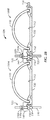
- Fig. 2A-2B are perspective and end views of lateral screens having a leveling hold-down mechanism according to certain teachings of the present disclosure.
- Figs. 3A-3B show top and side views of an outer leveling plate of the disclosed mechanism.
- Figs. 4A-4B show top and side views of an inner leveling plate of the disclosed mechanism.
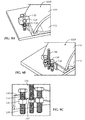
- Figs. 5A-5D are perspective, top, end, and side views of an outer hold-down bar.
- Figs. 6A-6D are perspective, top, end, and side views of an inner hold-down bar.
- Figs. 7A-7B show side views of alternate hold-down bars.
- Figs. 8A-8B shows a plan view of a basin having drop pipes and arrangements of lateral screens during assembly procedures.
- Figs. 9A-9C show steps for assembling the outer hold-down plate and bar on a lateral screen.
- Figs. 10A-10B show side and plan views of the outer hold-down plate and bar installed on a lateral screen.
- Fig. 11 shows a plan view of the basin having a subsequent arrangement of lateral screens during assembly procedures.
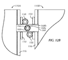
- Figs. 12A-12B show side and plan views of the inner hold-down plate and bar installed on lateral screens.
- Figures 2A-2B show perspective and end views of lateral screens 100A-B having a leveling hold-down mechanism 120 according to certain teachings of the present disclosure.
- the mechanism 120 helps maintain the lateral screens 100A-B in a level state and holds them in place during normal operation (downflow) and backwash (upflow) in an underdrain system.
- the lateral screens 100A-B can be similar to the lateral screens of Johnson Screen's Triton ® Underdrain System.
- each lateral screen 100 has a screen element 110 that slides into channels 114 along the longitudinal edges 116 of a base plate 112.
- the screen element 110 is composed of PVC Vee-Wire ® wound around and welded to "U" shaped channel rods as described previously.
- the base plate 112 is composed of extruded PVC and has a central opening (not shown) for affixing on a drop pipe with a seal or the like.
- the screen element 110 can also be made of other materials, such as stainless steel or as required by the process in which the screen will be used.
- the mechanism 120 uses two different hold-down assemblies 123/125 for an installation depending on the location of the lateral screens 100A-B in a basin.
- An outer hold-down assembly 123 has an outer leveling plate 130 with leveling bolts 138 and has an outer hold-down bar 140 with an anchor bolt 146. Because the screens 100A-B are normally installed side-by-side on the basin floor, the outer hold-down assembly 123 is used for the end or last screen 100A on either end of the basin as described in more detail below.
- An inner hold-down assembly 125 has an inner leveling plate 150 with leveling bolts 158 and has an outer hold-down bar 160 with an anchor bolt 166. This inner hold-down assembly 125 is used between lateral screens 100A-B on the basin floor as described in more detail below.
- the plates 130/150, bars 140/160, bolts 138/158, and the like are separate components from the lateral screens 100A-B, rather than being welded/attached to them. This allows for easier adjustment and placement of the screens 100A-B during installation. It also allows for more accurate leveling of the plastic lateral screens 100A-B, which are typically leveled using shims in the less reliable manner of the prior art.
- the leveling plates 130/150 support the bottom of the lateral screens 100A-B at appropriate intervals along their length.
- the spacing between plates 130/150 along the length of a screen 100 is dependent on the weight of the water and media in the basin and the expected hydraulic forces encountered during backwash.
- Leveling bolts 138/158 on the sides of the plates 130/150 can be used to raise the plates 130/150 and the supported section of the screens 100A-B to effectively level the screens 100A-B.
- the threaded anchor bolts 146/166 are placed next to or between the screens 100A-B depending on their location in the basin, and hold-down bars 140/160 are placed on the threaded anchor bolts 146/166.
- a nut/washer arrangement then clamps the bars 140/160 to the screens 100A-B and the plates 130/150.
- the bars 140/160 are sized and positioned in such a way as to restrict any turning motion of the adjacent leveling bolts 138/158.
- the components of the mechanism 120 can be made of a variety of materials so that any special alloys can be used when required in desalination plants or other corrosive environments.
- the components of the mechanism 120 can also be standardized and can be used in many installations without modification.
- the mechanism 120 enables the plastic lateral screens 100A-B to be used in applications where they could not be used previously because the plastic lateral screens 100AB could not be adequately held down and leveled with prior art systems.
- the outer leveling plate 130 has upward extending sides or edges 132o-i defining notches 134 on top.
- a number of nuts 136 weld to the sides132o-i, although other ways of including threading openings in the sides 132o-i could be used.
- the outer side 132o has two nuts 136 on either side of the notch 134, while the inner side 132i has one nut 136 on one side of the notch 134.
- adjustment bolts 138 install in these side nuts 136 for adjusting the level of the plate 130 when disposed on a basin floor as described below.
- the inner leveling plate 150 also has upward extending sides or edges 152o-i defining notches 154 on top.
- a number of nuts 156 weld to the sides 152o-i, although other ways of including threading openings in the sides 152o-i could be used.
- the outer side 152o has one nut 156 on one side of the notch 154, while the inner side 152i has one nut 156 on the opposite side of the notch 154.
- adjustment bolts 158 install in the side nuts 156 for adjusting the level of the plate 150 when disposed on a basin floor as described below.
- the outer hold-down bar 140 has a through-hole 142 that is off center and toward an outer edge.
- An extended end 144 of the bar 140 can be used for holding down an edge 116 of a lateral screen 100 as shown previously in Figures 2A-2B , for example.
- the inner edge of the bar 140 can have a chamfer 146 so as not to damage the screen element 110.
- the inner hold-down bar 160 has a through-hole 162 defined in the center. Extended ends 164 on either side of the hole 162 can be used for holding down edges 116 of adjacent lateral screens 100A-B as shown previously in Figures 2A-2B , for example. Both edges of the bar 160 can have a chamfer 166 so as not to damage the screen elements 110.
- the inner hold-down bar 160 can have a central rim to center it when installed in the assembly between the adjacent support plates. Also, the outside edges of the bar 160 can be tapered as in Figure 7B to avoid or enhance contact with the screen (not shown).
- leveling hold-down mechanism 120 With an understanding of the components of the leveling hold-down mechanism 120, discussion now turns to steps for installing lateral screens 100A-B with the mechanism 120 in a basin. Initially, operators install the leveling bolts 138/158 into the hold-down plates 130/150 so that distal ends of the bolts 138/158 are flush with the bottom surfaces of the plates 130/150.
- outer hold-down bar 140 As shown in Figure 9A , operators use the outer hold-down bar 140 as a guide to mark the locations of the holes to be drilled for the anchor bolts (146). For proper placement, the outer hold-down bar 140 is preferably placed at least past the halfway point on the edge 116 of the screen's base plate 112, but not in contact with the screen element 110. As expected, the chamfered edge of the hold-down bar 140 fits at the base plate's edge 116.
- each set of anchor holes can be drilled and bolts 146 set separately for each screen element 110 as operators continue installing along the basin floor for other types of anchors.
- the lateral screen 100A is leveled within a tolerance of ⁇ 0.25" down the entire length of the screen 100A. Therefore, operators preferably use a surveyor's level. The intent is to level each lateral screen 100 to within a specified tolerance rather than level one screen 100 to another. However, the leveling system can be used to achieve this goal as well.
- the nuts 148a can be tightened to a specified torque. If an adhesive style anchor system is used, the adhesive for the anchor bolt 146 should be cured before tightening the nuts 148a.
- the outer hold-down assembly 123 holds the outside longitudinal edge 116 of the first lateral screen 100A as shown in Figures 10A-10B . Locking nuts or other methods can be used to prevent these nuts 148a-b from loosening during service.
Landscapes
- Chemical & Material Sciences (AREA)
- Chemical Kinetics & Catalysis (AREA)
- Filtration Of Liquid (AREA)
Applications Claiming Priority (1)
| Application Number | Priority Date | Filing Date | Title |
|---|---|---|---|
| US13/157,043 US8491787B2 (en) | 2011-06-09 | 2011-06-09 | Leveling hold-down mechanism for lateral screens |
Publications (1)
| Publication Number | Publication Date |
|---|---|
| EP2532404A1 true EP2532404A1 (fr) | 2012-12-12 |
Family
ID=46298260
Family Applications (1)
| Application Number | Title | Priority Date | Filing Date |
|---|---|---|---|
| EP12171359A Withdrawn EP2532404A1 (fr) | 2011-06-09 | 2012-06-08 | Mécanisme de maintien à niveau pour écrans latéraux |
Country Status (5)
| Country | Link |
|---|---|
| US (1) | US8491787B2 (fr) |
| EP (1) | EP2532404A1 (fr) |
| JP (1) | JP5344652B2 (fr) |
| AU (1) | AU2012203324B2 (fr) |
| CA (1) | CA2779138C (fr) |
Cited By (1)
| Publication number | Priority date | Publication date | Assignee | Title |
|---|---|---|---|---|
| JP2023537040A (ja) * | 2020-08-05 | 2023-08-30 | アクセプタンス グループ インコーポレイテッド | 形状決定された暗渠アセンブリを有するバイオフィルタ |
Families Citing this family (5)
| Publication number | Priority date | Publication date | Assignee | Title |
|---|---|---|---|---|
| JP6153365B2 (ja) * | 2013-03-29 | 2017-06-28 | 株式会社クボタ | 集水装置の施工方法 |
| CN104947635A (zh) * | 2015-07-27 | 2015-09-30 | 苏州汇诚智造工业设计有限公司 | 一种泵站弧形阻水拦污栅栅片及其制造、施工和使用方法 |
| CN106702975B (zh) * | 2015-09-06 | 2018-09-21 | 苏州汇诚智造工业设计有限公司 | 一体式泵站闸门拦污栅的使用方法 |
| WO2018213563A1 (fr) | 2017-05-17 | 2018-11-22 | Xylem Water Solutions Zelienople Llc | Dispositif de retenue de milieux filtrants et système de drain de sortie comportant un dispositif de retenue de milieux filtrants |
| US12246271B2 (en) * | 2023-04-04 | 2025-03-11 | De Nora Water Technologies, LLC | Media retention plate for a block underdrain system |
Citations (5)
| Publication number | Priority date | Publication date | Assignee | Title |
|---|---|---|---|---|
| US2528065A (en) * | 1948-01-22 | 1950-10-31 | Dorr Co | Liquid-permeable tank bottom for beds of granular material |
| US4096911A (en) | 1977-07-05 | 1978-06-27 | Uop Inc. | Channel base well screen |
| US5156738A (en) | 1991-06-21 | 1992-10-20 | Johnson Filtration Systems Inc. | Apparatus for uniformly distributing gas and/or liquid in an underdrain lateral system |
| US5618426A (en) | 1995-06-15 | 1997-04-08 | Wheelabrator Water Technologies Inc. | Lateral member assembly for underdrain lateral system |
| US6797166B1 (en) * | 1999-04-30 | 2004-09-28 | Newtech Filter Systems, Inc. | Underdrain apparatus |
Family Cites Families (9)
| Publication number | Priority date | Publication date | Assignee | Title |
|---|---|---|---|---|
| US980442A (en) * | 1910-01-04 | 1911-01-03 | Canton Culvert Company | Draining-culvert. |
| US1071185A (en) * | 1913-03-06 | 1913-08-26 | William T Shannon | Sheet-metal culvert. |
| US2873857A (en) * | 1955-05-16 | 1959-02-17 | Union Tank Car Co | Filter underdrain system |
| US4331542A (en) * | 1980-08-01 | 1982-05-25 | Enviroquip, Inc. | Underdrain unit with air/water backwash for granular filtration system |
| JPS58176173U (ja) * | 1982-05-18 | 1983-11-25 | 村橋 義雄 | 集水埋渠による取水装置 |
| JPH0686904A (ja) * | 1992-08-17 | 1994-03-29 | Johnson Filtration Syst Inc | 地下排水管分配装置 |
| JP3247547B2 (ja) * | 1994-06-10 | 2002-01-15 | 株式会社郷設計研究所 | 冷却用ろ過循環貯水池構造 |
| US6569328B1 (en) * | 2000-11-02 | 2003-05-27 | Gary D. Haggard | Underdrain filtration system with stamped perforations |
| US7820043B2 (en) * | 2006-04-10 | 2010-10-26 | Rg Delaware Inc. | Underdrain system |
-
2011
- 2011-06-09 US US13/157,043 patent/US8491787B2/en not_active Expired - Fee Related
-
2012
- 2012-06-06 AU AU2012203324A patent/AU2012203324B2/en not_active Ceased
- 2012-06-07 CA CA2779138A patent/CA2779138C/fr not_active Expired - Fee Related
- 2012-06-07 JP JP2012129595A patent/JP5344652B2/ja not_active Expired - Fee Related
- 2012-06-08 EP EP12171359A patent/EP2532404A1/fr not_active Withdrawn
Patent Citations (5)
| Publication number | Priority date | Publication date | Assignee | Title |
|---|---|---|---|---|
| US2528065A (en) * | 1948-01-22 | 1950-10-31 | Dorr Co | Liquid-permeable tank bottom for beds of granular material |
| US4096911A (en) | 1977-07-05 | 1978-06-27 | Uop Inc. | Channel base well screen |
| US5156738A (en) | 1991-06-21 | 1992-10-20 | Johnson Filtration Systems Inc. | Apparatus for uniformly distributing gas and/or liquid in an underdrain lateral system |
| US5618426A (en) | 1995-06-15 | 1997-04-08 | Wheelabrator Water Technologies Inc. | Lateral member assembly for underdrain lateral system |
| US6797166B1 (en) * | 1999-04-30 | 2004-09-28 | Newtech Filter Systems, Inc. | Underdrain apparatus |
Cited By (2)
| Publication number | Priority date | Publication date | Assignee | Title |
|---|---|---|---|---|
| JP2023537040A (ja) * | 2020-08-05 | 2023-08-30 | アクセプタンス グループ インコーポレイテッド | 形状決定された暗渠アセンブリを有するバイオフィルタ |
| EP4192790A4 (fr) * | 2020-08-05 | 2024-01-17 | Aqseptence Group, Inc. | Biofiltre ayant un ensemble drain souterrain façonné |
Also Published As
| Publication number | Publication date |
|---|---|
| US20120312728A1 (en) | 2012-12-13 |
| CA2779138C (fr) | 2014-12-02 |
| CA2779138A1 (fr) | 2012-12-09 |
| US8491787B2 (en) | 2013-07-23 |
| AU2012203324B2 (en) | 2013-12-05 |
| AU2012203324A1 (en) | 2013-01-10 |
| JP5344652B2 (ja) | 2013-11-20 |
| JP2012255331A (ja) | 2012-12-27 |
Similar Documents
| Publication | Publication Date | Title |
|---|---|---|
| AU2012203324B2 (en) | Leveling hold-down mechanism for lateral screens | |
| US7138056B2 (en) | Filter underdrain system for backwash flow and method for measuring same | |
| JPS5825484B2 (ja) | 多セル式粒状材濾過装置 | |
| US20100314305A1 (en) | Underdrain Apparatus | |
| US9932730B2 (en) | Trench drain | |
| US20190218764A1 (en) | Underdrain assembly | |
| JP6042717B2 (ja) | 汚泥掻き寄せ装置 | |
| CN204626348U (zh) | 用于调节流量分配的可调节堰板 | |
| JP6042716B2 (ja) | 汚泥掻き寄せ装置 | |
| EP2388374A2 (fr) | Fixation de rails | |
| JP6710148B2 (ja) | バースクリーン式除塵機 | |
| AT400734B (de) | Tauchwandanordnung in einer regenwasseranlage | |
| DE102006039250A1 (de) | Wärmetauscher aus Wellrohr für Abwasser u. Oberflächenwasser | |
| KR102199601B1 (ko) | 막 조절이 가능한 도류벽 시스템 및 그 설치공법 | |
| CN116536998B (zh) | 一种预制装配式道路结构 | |
| KR102455364B1 (ko) | 밴드를 이용한 패널형 도류벽 설치수단 | |
| JP2001300216A (ja) | ディスク型ストレーナ | |
| CN113914209B (zh) | 桥梁伸缩缝装置以及施工方法 | |
| KR101950600B1 (ko) | 이물질 제거 및 유량조절이 가능한 배수장치 | |
| CA2543681C (fr) | Systeme drainant souterrain filtrant pour flux de retour et methode pour mesurer celui-ci | |
| CN117379846A (zh) | 可调节式滤池配水系统及其施工方法 | |
| JPS5813206B2 (ja) | 傾斜板沈殿分離装置 | |
| CA1313504C (fr) | Systeme filtrant de drainage souterrain | |
| JPH08135006A (ja) | 下水道暗渠の補修構造 | |
| KR20080038949A (ko) | 도로설치용 높낮이 조절형 집수구 |
Legal Events
| Date | Code | Title | Description |
|---|---|---|---|
| PUAI | Public reference made under article 153(3) epc to a published international application that has entered the european phase |
Free format text: ORIGINAL CODE: 0009012 |
|
| 17P | Request for examination filed |
Effective date: 20120608 |
|
| AK | Designated contracting states |
Kind code of ref document: A1 Designated state(s): AL AT BE BG CH CY CZ DE DK EE ES FI FR GB GR HR HU IE IS IT LI LT LU LV MC MK MT NL NO PL PT RO RS SE SI SK SM TR |
|
| AX | Request for extension of the european patent |
Extension state: BA ME |
|
| RAP1 | Party data changed (applicant data changed or rights of an application transferred) |
Owner name: BILFINGER WATER TECHNOLOGIES, INC. |
|
| GRAP | Despatch of communication of intention to grant a patent |
Free format text: ORIGINAL CODE: EPIDOSNIGR1 |
|
| INTG | Intention to grant announced |
Effective date: 20150924 |
|
| STAA | Information on the status of an ep patent application or granted ep patent |
Free format text: STATUS: THE APPLICATION IS DEEMED TO BE WITHDRAWN |
|
| 18D | Application deemed to be withdrawn |
Effective date: 20160205 |