EP2532794A2 - Dispositif de fixation mobile d'une pomme de douche - Google Patents
Dispositif de fixation mobile d'une pomme de douche Download PDFInfo
- Publication number
- EP2532794A2 EP2532794A2 EP20120168842 EP12168842A EP2532794A2 EP 2532794 A2 EP2532794 A2 EP 2532794A2 EP 20120168842 EP20120168842 EP 20120168842 EP 12168842 A EP12168842 A EP 12168842A EP 2532794 A2 EP2532794 A2 EP 2532794A2
- Authority
- EP
- European Patent Office
- Prior art keywords
- pressure piece
- actuating element
- base body
- nut
- opening
- Prior art date
- Legal status (The legal status is an assumption and is not a legal conclusion. Google has not performed a legal analysis and makes no representation as to the accuracy of the status listed.)
- Withdrawn
Links
- 238000003780 insertion Methods 0.000 description 9
- 230000037431 insertion Effects 0.000 description 9
- 238000006073 displacement reaction Methods 0.000 description 4
- 230000000694 effects Effects 0.000 description 2
- 239000011295 pitch Substances 0.000 description 2
- 230000015572 biosynthetic process Effects 0.000 description 1
- 238000004140 cleaning Methods 0.000 description 1
- 238000005553 drilling Methods 0.000 description 1
- 238000009434 installation Methods 0.000 description 1
- 238000004519 manufacturing process Methods 0.000 description 1
- 239000000463 material Substances 0.000 description 1
- 239000002184 metal Substances 0.000 description 1
Images

Classifications
-
- E—FIXED CONSTRUCTIONS
- E03—WATER SUPPLY; SEWERAGE
- E03C—DOMESTIC PLUMBING INSTALLATIONS FOR FRESH WATER OR WASTE WATER; SINKS
- E03C1/00—Domestic plumbing installations for fresh water or waste water; Sinks
- E03C1/02—Plumbing installations for fresh water
- E03C1/06—Devices for suspending or supporting the supply pipe or supply hose of a shower-bath
- E03C1/066—Devices for suspending or supporting the supply pipe or supply hose of a shower-bath allowing height adjustment of shower head
Definitions
- the invention relates to a device for movably mounting a shower to a pole.
- Such devices are known from the prior art and often have a base body in which a pressure piece is movably mounted. This pressure piece can be moved by means of an actuating element to the rod out or away from the rod, so as to fix the base body at a respectively desired height on the rod.
- the devices known from the prior art have a number of disadvantages.
- the vertical displacement of the main body often creates annoying scratch marks on the rod, since there is a direct contact between the pressure piece and rod during the displacement. Often this contact is made on the well visible front of the bar, so that scratch marks are particularly disturbing in this case.
- the actuator is often formed in known devices as standing with the pressure piece operatively connected knob, which must be rotated to release the pressure piece or to fix the pressure piece on the rod to a relatively large angular range, which makes handling difficult.
- the assembly of the known devices often designed relatively complicated, resulting in a disadvantageous increased economic effort.
- the object of the invention is to design a device of the type mentioned in such a way that disturbing scratches on the rod are at least largely avoided, in particular, a simple handling and installation of the device should be given.
- the structure according to the invention makes it possible for both the pressure piece and the actuating element to be arranged laterally on the rod, so that the pressure piece has no contact with the front of the rod. In this way, disturbing scratch marks on the front of the bar can be completely avoided. Furthermore, if sufficiently large thread pitches are selected in the case of the two threaded elements provided according to the invention, it is also possible to release or produce a clamping effect between the pressure piece and the rod even with a comparatively small angle of rotation of the actuating element. This allows a convenient and advantageous operation of the device according to the invention.
- the threaded element of the actuating element can be designed as a threaded bolt and the threaded element of the pressure piece can be designed as a nut or vice versa.
- at least partially commercial components can be used as threaded elements, which can reduce the manufacturing cost. It when the threaded bolt is provided on the side of the actuating element and screwed into this is particularly advantageous.
- Such a threaded bolt then has a first thread for screwing into the actuating element and a second thread which is screwed into the nut of the pressure piece.
- For screwing into the actuating element of the threaded bolt has a trained in particular as an Allen attack surface for a commercial tool.
- threaded bolt is understood to mean not only the region which is in communication with the nut, but rather the complete component including the section which is screwed into the actuating element.
- this may have a recess for non-rotatably receiving the nut.
- a recess preferably has, in addition to a base surface on which the nut rests with one end face, two contact surfaces extending parallel to the pivot axis for rotationally fixed fixing of the nut.
- the mother is rotationally fixed by these two contact surfaces according to the principle of a wrench on the pressure piece. In this arrangement, it is advantageous that it is sufficient to position the nut during assembly only between these contact surfaces, without the need for further fixation of the nut on the pressing piece.
- the mother can therefore between the contact surfaces in principle perpendicular to its threaded axis be moved, but such a shift is no longer possible after the threaded bolt has been screwed into the nut, since this then causes a fixation of the nut perpendicular to its threaded axis.
- the threaded bolt facing away from the front side of the nut acts on the above-mentioned base of the recess of the pressure piece.
- the side facing away from the base of the pressure piece is designed as a pressure surface, which in turn is then suitable to transmit pressure forces directly to the rod.
- a plate attached to the base plate may be provided, which has a central opening for the passage of the threaded bolt. If, in this case, the nut is received in a recess of the pressure piece and the threaded bolt is screwed into the nut, is effected by the base body in particular by means of screws fixed plate that pressure piece, nut, threaded bolt, plate and actuator represent a unit whose items are captive connected to each other.
- a particularly advantageous operation of the device according to the invention can then be achieved if the thread pitches of threaded bolt and nut are chosen so that a pivoting movement of the actuating element by a pivot angle of 90 ° is sufficient to create or release a clamping action between the pressure piece and rod.
- the pivoting angle of the actuating element is then limited to 90 ° preferably by suitable mechanical measures. This can be achieved, for example, in that the plate mentioned above has a 90 ° guide slot and the actuating element has an extension engaging in this guide slot.
- the guide slot describes the shape of a quarter circle.
- the pressure piece has a particularly flat pressure surface for direct contact with the rod, wherein the pressure surface is preferably made of plastic.
- This pressure surface then forms a first, the rod-facing side of a pressure section of the pressure piece, while the other side of this pressure section forms the already mentioned base area for that end face of the mother, which faces away from the threaded bolt.
- the use of a flat pressure surface is particularly suitable when a rod with a square or rectangular cross-section is used, since in this case a relatively large, flat contact between the pressure piece and rod is generated, which additionally prevents the formation of disturbing scratch marks on the rod , In addition, the pressure surface prevents the nut from coming into direct contact with the rod.
- the pressure piece may have a through opening for receiving the rod, which is substantially aligned at a certain position of the actuating element with the through hole of the main body for receiving the rod.
- the pressure piece surrounds the rod completely and can at the same time close all the openings of the base body facing the rod, which facilitates the handling and in particular the cleaning of the device according to the invention.
- the opening for receiving the rod in the base body and / or in the pressure piece has a corresponding, also rectangular or square shape.
- the actuating element of the main body can be mounted in particular with respect to the main body pivotable effervescent receptacle, wherein the pivot axes of the actuating element and the Effervescent Receive parallel to each other or are identical.
- the device according to the invention can be given an attractive and balanced shape, since it can then extend approximately equidistant from the rod on both sides of the rod.
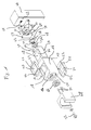
- two insertion pieces 20 are inserted into the base body via the open front side 14 of the main body 10 and then inserted from the inside into an opening 18.
- Both insert pieces 20 each have two extensions 22 extending in opposite directions, which prevent the insert pieces 20 from falling out of the openings 18 in the inserted state to the outside.
- Both insertion pieces 20 each have an opening 24 whose size is adapted to the circumference of the shower bar, not shown, so that the insertion pieces 20 ultimately frame the through opening 18 of the body 10 inside and prevent the shower bar in direct contact with the base body 10th arrives.
- the insertion pieces 20 are made of plastic, is achieved in this way that a displacement of the shower bar within the insertion pieces 20 and thus within the through hole 18 of the body leads to any scratch marks, which is particularly advantageous if the body 10 made a harder material, such as metal, is made.
- a pressure piece 26 is also substantially cuboid-shaped and dimensioned so that it can be inserted into insertion pieces 20 inserted from the end face 14 of the base body 10 forth in this. Also, the pressure piece 26 has a through opening 28 which is adapted to the cross section of the shower bar and whose opening area substantially corresponds to those of the openings 24 of the insertion pieces 20.
- a recess 30 is provided, which is bounded by a base 32 and two opposing abutment surfaces 34.
- the cuboid recess 30 serves to receive a nut 36, wherein the distance between the two contact surfaces 34 is dimensioned from each other so that the nut 36 is received against rotation in the recess 30.
- a threaded bolt 38 has a first thread 40 which can be screwed into the nut 36 and a second thread 42, which in a threaded hole 44 (see Fig. 1 ) of a trained as a lever actuator 46 can be screwed.
- the threaded bolt 38 has a circumferential collar 50 whose diameter corresponds approximately to the diameter of the nut 36.
- a substantially square plate 52 is provided whose size is adapted to the end face 14 of the base body 10. This plate 52 can be screwed by means of screws 54 with the end face 14 of the base body 10, so that the plate 52 at least largely closes this end face 14.
- a central opening 56 is provided, which is dimensioned so that the second thread 42 of the threaded bolt 38 can be inserted through this central opening 56.
- the plate 52 has a quarter-circle-shaped guide slot 58 into which an extension 60 can engage, which in a bore 62 (FIG. Fig. 1 ) of the actuating element 46 is anchored.
- the end face 12 of the main body 10 has a substantially circular, knurled recess 64, into which a latching element 66 can engage, wherein the latching element 66 is non-rotatably coupled to a shower receptacle 68 via pins 70.
- the effervescent receptacle 68 When assembling the device according to the invention, first the effervescent receptacle 68 can be fixed together with the latching element 66 fastened to it by means of a screw 72 on the end face 12 of the main body 10. The effervescent receptacle 68 is then pivotable about the axis of the screw 72 with correspondingly flexible design of locking element 66 or recess 64.
- the insertion pieces 20 are inserted into the base body 10, whereupon the pressure piece 26 is likewise pushed into the base body 10.
- the threaded bolt 50 is then inserted with the second thread 42 through the central opening 56 of the plate 52 and a washer 74, whereupon the second thread 42 is screwed into the threaded hole 44 of the actuating element 46.
- this screwing plate 52 and washer 74 are rotatably mounted by the collar 50 on the actuator 46.
- the nut 36 is screwed with a suitable number of revolutions on the first thread 40 of the threaded bolt 38, so that subsequently the nut 36 can be inserted into the recess 30 of the pressure piece 26.
- the actuating element 46 is then rotated relative to the position shown in the figures by approximately 45 ° relative to the plate 52, so that the holes provided in the corner regions of the plate 52 become accessible to the screws 54. In this position, the plate 52 can be secured by means of screws 54 on the base body 10. Subsequently, it is possible to pivot the actuating element 46 back into its position shown in the figures back.
- the device according to the invention which has been mounted completely in this way can be actuated, in which the actuating element 46 is pivoted back and forth by 90 ° relative to the main body 10, this maximum pivoting angle being defined by the guide slot 58 and the extension 60.
- the first thread 40 is either further screwed into the nut 36 or unscrewed from it depending on the pivoting direction.
- This relative movement between the first thread 40 and the nut 36 respectively causes a displacement of the pressure piece 26 in the respective desired direction along the longitudinal axis of the threaded bolt 38.
- a shower bar between the insides of the insert 20 and the pressure surface 76 of the pressure member 26 are clamped or It can be canceled such a clamping effect in the opposite direction of pivoting.
Landscapes
- Health & Medical Sciences (AREA)
- Life Sciences & Earth Sciences (AREA)
- Engineering & Computer Science (AREA)
- Hydrology & Water Resources (AREA)
- Public Health (AREA)
- Water Supply & Treatment (AREA)
- Pivots And Pivotal Connections (AREA)
- Connection Of Plates (AREA)
Applications Claiming Priority (1)
| Application Number | Priority Date | Filing Date | Title |
|---|---|---|---|
| DE201110103782 DE102011103782A1 (de) | 2011-06-09 | 2011-06-09 | Vorrichtung zur beweglichen Halterung einer Brause |
Publications (1)
| Publication Number | Publication Date |
|---|---|
| EP2532794A2 true EP2532794A2 (fr) | 2012-12-12 |
Family
ID=46168179
Family Applications (1)
| Application Number | Title | Priority Date | Filing Date |
|---|---|---|---|
| EP20120168842 Withdrawn EP2532794A2 (fr) | 2011-06-09 | 2012-05-22 | Dispositif de fixation mobile d'une pomme de douche |
Country Status (2)
| Country | Link |
|---|---|
| EP (1) | EP2532794A2 (fr) |
| DE (1) | DE102011103782A1 (fr) |
Family Cites Families (3)
| Publication number | Priority date | Publication date | Assignee | Title |
|---|---|---|---|---|
| SE394706B (sv) * | 1976-09-17 | 1977-07-04 | N Larsson | Duschhallare |
| DE19827350A1 (de) * | 1998-06-19 | 1999-12-30 | Wilke Heinrich Hewi Gmbh | Vorrichtung zur verschiebbaren Montage eines Gegenstands, insbesondere einer Handbrause, an einer Tragstange |
| GB2443704A (en) * | 2006-11-13 | 2008-05-14 | Kuldip Singh Kanth | Mounting a shower head on a shower rail |
-
2011
- 2011-06-09 DE DE201110103782 patent/DE102011103782A1/de not_active Withdrawn
-
2012
- 2012-05-22 EP EP20120168842 patent/EP2532794A2/fr not_active Withdrawn
Also Published As
| Publication number | Publication date |
|---|---|
| DE102011103782A1 (de) | 2012-12-13 |
Similar Documents
| Publication | Publication Date | Title |
|---|---|---|
| EP2851497B1 (fr) | Dispositif de montage réglable pour un élément coulissant et dispositif coulissant | |
| DE202010008393U1 (de) | Verbindungsvorrichtung | |
| DE102010062565B4 (de) | Winkelverstellbarer Handgriff für ein Handwerkzeug | |
| EP2742199B1 (fr) | Système de fixation pour fixer une pièce sur une rainure d'une fenêtre, d'une porte ou analogue | |
| DE20209159U1 (de) | Schnellsicherung für Verlängerungen von Steckwerkzeugen | |
| EP2875199B1 (fr) | Guide pour tringle de crémone | |
| DE212020000339U1 (de) | Tragvorrichtung für Möbelfachböden | |
| DE202004001161U1 (de) | Klipsbefestigung für die Schnellmontage von Beschlageinrichtungen, wie Schwenkhebelverschlüsse, Scharnierteile in einer dünnen Wand | |
| EP1817983A1 (fr) | Dispositif pour influencer le mouvement des parties de meuble l'une par rapport à l'autre et une glissière pour tiroirs, ainsi qu'un procédé de fabrication d'un tel dispositif | |
| EP3386678A1 (fr) | Dispositif d'accouplement et de désaccouplement automatisé d'une fixation d'outil et procédé de raccordement automatisé d'au moins deux pièces | |
| EP3098357A1 (fr) | Dispositif d'actionnement de soupape de vidange d'un réservoir de chasse | |
| EP2949842A1 (fr) | Système de poignée de porte pour un véhicule | |
| EP3243008B1 (fr) | Raccord de liaison | |
| DE29505752U1 (de) | Vorrichtung zum Verbinden von Platten mittels Verschraubung | |
| DE102013113915A1 (de) | Federklemmung mit Öffnungsbegrenzer | |
| DE3720790C2 (de) | Handbetätigbare Verriegelungsanordnung zum Befestigen eines beweglichen Teiles an einem festen Teil | |
| DE2619340C3 (de) | Vorrichtung zur abnehmbaren Halterung von elektrischen Baueinheiten an einem Lagergestell | |
| EP2532794A2 (fr) | Dispositif de fixation mobile d'une pomme de douche | |
| DE102009007328B4 (de) | Verbindungsvorrichtung zum Verbinden zweier unter einem Winkel < 180° zueinander stehender plattenförmiger Elemente | |
| DE69002342T2 (de) | Befestigungsvorrichtung durch Zusammenschrauben auf einem Profil, insbesondere auf einem Elektrizitätsschrank. | |
| DE102015205623B4 (de) | Manuelles Schraubwerkzeug | |
| DE9104766U1 (de) | Antipaniktürschloß | |
| EP2578891A1 (fr) | Adapteur | |
| DE9304388U1 (de) | Fallenschloß mit umstellbarer Schloßfalle | |
| EP1084660B1 (fr) | Dispositif pour l'ajustage vertical de tiroirs de meuble |
Legal Events
| Date | Code | Title | Description |
|---|---|---|---|
| PUAI | Public reference made under article 153(3) epc to a published international application that has entered the european phase |
Free format text: ORIGINAL CODE: 0009012 |
|
| AK | Designated contracting states |
Kind code of ref document: A2 Designated state(s): AL AT BE BG CH CY CZ DE DK EE ES FI FR GB GR HR HU IE IS IT LI LT LU LV MC MK MT NL NO PL PT RO RS SE SI SK SM TR |
|
| AX | Request for extension of the european patent |
Extension state: BA ME |
|
| STAA | Information on the status of an ep patent application or granted ep patent |
Free format text: STATUS: THE APPLICATION IS DEEMED TO BE WITHDRAWN |
|
| 18D | Application deemed to be withdrawn |
Effective date: 20151201 |