EP2532799B1 - Metallträger und dessen Verwendung - Google Patents
Metallträger und dessen Verwendung Download PDFInfo
- Publication number
- EP2532799B1 EP2532799B1 EP20110004788 EP11004788A EP2532799B1 EP 2532799 B1 EP2532799 B1 EP 2532799B1 EP 20110004788 EP20110004788 EP 20110004788 EP 11004788 A EP11004788 A EP 11004788A EP 2532799 B1 EP2532799 B1 EP 2532799B1
- Authority
- EP
- European Patent Office
- Prior art keywords
- metal
- pressed
- reinforcing ribs
- web
- girder according
- Prior art date
- Legal status (The legal status is an assumption and is not a legal conclusion. Google has not performed a legal analysis and makes no representation as to the accuracy of the status listed.)
- Active
Links
Images




Classifications
-
- E—FIXED CONSTRUCTIONS
- E04—BUILDING
- E04B—GENERAL BUILDING CONSTRUCTIONS; WALLS, e.g. PARTITIONS; ROOFS; FLOORS; CEILINGS; INSULATION OR OTHER PROTECTION OF BUILDINGS
- E04B9/00—Ceilings; Construction of ceilings, e.g. false ceilings; Ceiling construction with regard to insulation
- E04B9/06—Ceilings; Construction of ceilings, e.g. false ceilings; Ceiling construction with regard to insulation characterised by constructional features of the supporting construction, e.g. cross section or material of framework members
- E04B9/065—Ceilings; Construction of ceilings, e.g. false ceilings; Ceiling construction with regard to insulation characterised by constructional features of the supporting construction, e.g. cross section or material of framework members comprising supporting beams having a folded cross-section
- E04B9/067—Ceilings; Construction of ceilings, e.g. false ceilings; Ceiling construction with regard to insulation characterised by constructional features of the supporting construction, e.g. cross section or material of framework members comprising supporting beams having a folded cross-section with inverted T-shaped cross-section
- E04B9/068—Ceilings; Construction of ceilings, e.g. false ceilings; Ceiling construction with regard to insulation characterised by constructional features of the supporting construction, e.g. cross section or material of framework members comprising supporting beams having a folded cross-section with inverted T-shaped cross-section with double web
-
- B—PERFORMING OPERATIONS; TRANSPORTING
- B21—MECHANICAL METAL-WORKING WITHOUT ESSENTIALLY REMOVING MATERIAL; PUNCHING METAL
- B21D—WORKING OR PROCESSING OF SHEET METAL OR METAL TUBES, RODS OR PROFILES WITHOUT ESSENTIALLY REMOVING MATERIAL; PUNCHING METAL
- B21D39/00—Application of procedures in order to connect objects or parts, e.g. coating with sheet metal otherwise than by plating; Tube expanders
- B21D39/03—Application of procedures in order to connect objects or parts, e.g. coating with sheet metal otherwise than by plating; Tube expanders of sheet metal otherwise than by folding
- B21D39/035—Joining superposed plates by slitting
-
- B—PERFORMING OPERATIONS; TRANSPORTING
- B21—MECHANICAL METAL-WORKING WITHOUT ESSENTIALLY REMOVING MATERIAL; PUNCHING METAL
- B21D—WORKING OR PROCESSING OF SHEET METAL OR METAL TUBES, RODS OR PROFILES WITHOUT ESSENTIALLY REMOVING MATERIAL; PUNCHING METAL
- B21D47/00—Making rigid structural elements or units, e.g. honeycomb structures
- B21D47/01—Making rigid structural elements or units, e.g. honeycomb structures beams or pillars
Definitions
- the invention relates to a metal support for a ceiling substructure with a T-profile of a double sheet, wherein the metal support is characterized by the features of the characterizing part of claim 1.
- the invention further relates to the use of such a metal support for metallic ceiling substructures as the main and / or cross member, wherein the flange points in the direction of the interior of the room.
- Metal supports of the generic type for ceiling substructures are known in the art. That's how it describes GB 2 456 328 A a corresponding metal carrier, which is designed in the form of a T-profile is.
- the metal support according to the British application is also formed from a double sheet and has at the web-side end of a hollow profile.
- the linear hollow profiles are formed by the double plate and are present substantially over the entire length of the metal carrier.
- GB 2 274 080 A shows a metal carrier according to the preamble of claim 1.
- the metal carrier in the web area with reinforcing ribs ("stitching"), wherein the reinforcing ribs have been pressed both from the outside of the first sheet in the direction of the second sheet as well as from the outside of the second sheet in the direction of the first sheet ,
- the core of the invention is thus a "double-sided stitching".
- the metal carrier is designed so that the pressed-in reinforcing ribs ("stitching") parallel to the flange in line shape, preferably over the entire length of the metal carrier, are pressed.
- the invention in this case comprises embodiments in which the press-ins are alternately, i. from one side and the other side, as well as embodiments in which there are several pressings successively from one side and then again several pressings in succession from the other side.
- the reinforcing ribs alternate in a line shape in each case, i. an injection from the outside of the first sheet in the direction of the second sheet, and then the next press-in from the other side of the sheet are introduced.
- the distances between the pressings can also be variable.
- a further preferred embodiment then provides that the reinforcing ribs are pressed into two or three lines arranged parallel to the flange. Within the respective parallel lines with the "stitching", the number of impressions that are pressed in from the first side in the direction of the second side and vice versa may vary.
- the invention also includes embodiments in such a way that the reinforcing ribs are pressed in line form starting from the outside of one of the sheets and are pressed in parallel in a second line arranged therefrom, starting from the outside of the other sheet.
- the reinforcing ribs of the two lines are arranged on a gap are, that is, a press-fitting, which is pressed from one side in the direction of the other sheet, is offset from the other press-in, which has been introduced from the other side, arranged.
- the pressed-in reinforcing ribs are arranged parallel to the flange in line form in the vicinity of the flange.
- a further preferred embodiment then provides that reinforcing ribs are provided in a second line parallel thereto, wherein these reinforcing ribs are then provided at the web-side end.
- the impressions are preferably provided in the last third of the web area.
- the two-sided "stitching" can not be distributed in line form, but distributed over the surfaces of the web area. Also for this embodiment, the number of press-in is variable.
- the reinforcing ribs are introduced into the web by a two-step process.
- a tab is cut free from the material.
- the second process step is then carried out by a stamp pressing, so that a flow of the material of the tab takes place. By this pressing is then ensured that the tab can not be pushed back into the recess.
- the invention also includes embodiments in which the compression is produced by a one-step process, i. In one operation, the tab is cut free and pressed.
- the compression is made by a single punch or by a double punch in a rectangular shape.
- the long sides of the rectangle are in the range of 2 to 8 mm and the short sides are 0.1 to 1.5 mm long.
- This linear reinforcing profile can be formed as a hollow profile by the two double sheets and is preferably arranged parallel to the line-shaped "stitching". In this case, a preferred embodiment provides that the linear reinforcing profile is arranged between two line-shaped pressings.
- the metal carriers according to the invention may additionally, as is known per se from the prior art, still have openings which are provided for latching the metal carriers to one another.
- the metal carriers according to the invention may then also have connectors, which are arranged on the front side at the respective ends of the metal carrier, which are provided to lock the metal carrier with each other through the opening.
- the metal carriers according to the invention may be metal carriers of a length of 50 to 400 cm, depending on the application. Such metal beams can be used for ceiling substructures, which then act either as a main or as a cross member.
- the selection of the length of the metal support depends of course on the application, i. depending on whether it is a main or a cross member.
- the T-profile of the metal carrier preferably has a web height in the web region between 1 and 8 cm.
- the material of the metallic supports is preferably a steel sheet of a cold-rolled strip.
- the steel grades include integrated carbon steels with carbon mass fractions up to 1%, a preferred steel sheet is DX 51 Z 100.
- the metal support according to the invention is as described above particularly suitable for metallic ceiling substructures as the main and / or cross member, wherein the flange points in the direction of the interior of the room.
- FIG. 1 is shown in cross section a metal carrier 1 in the form of an inverse T-profile.
- the metal carrier after FIG. 1 is formed of a double sheet 3, 4 and has at its web-end a hollow profile 5, which has been formed by the two double sheets.
- FIG. 1 is now seen in cross-section that the pressings (stitching) 6, 6 'have been introduced from both sides in the web portion 2 of the metal carrier 1.
- a first line shape has been formed at the flange end, in which case the press-in 6 from one side, ie from the outside of the sheet 3, have been introduced, whereas the press-in 6 'have been pressed from the outside of the sheet 4.
- the embodiment according to FIG. 1 thus has a double-sided stitching, each with two lines are provided with alternating pressings.
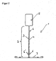
- FIG. 2 now corresponds to the one after FIG. 1
- the indentations 6 have been introduced at the web-side end only from one side, ie only from the outside of the sheet 3.
- the indentations 6, 6 ' which are arranged at the flange end, always from the outer side. 3 (Press 6) and from the outside 4 (press 6 ') have been made.
- FIG. 3 Now, a metal carrier according to the invention is shown, which by the example FIG. 2 emanating and differs in that between the flange-side line-shaped press-in and the web-side linear press-in nor a hollow section 8, which is formed by the two sheets 3, 4, is arranged. This achieves a further improvement in rigidity and distortion.
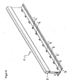
- FIG. 4 is now a perspective view of a metal support 1, which illustrates that the press-in 6, 6 'in line form and thereby alternately formed at the flange-side end of the web portion 2.
- the press-6 has been made from the non-visible page in the page shown.
- the invention of course includes all embodiments in which, for example, then two or three pressings have been made in the same direction and then two or three pressings have been carried out from the other side.
- the invention also includes embodiments in which, for example, in one line only 20% or 30% of the impressions have been made in one direction and correspondingly 80% or 70% of the impressions from the other direction.
- FIG. 5 is now in turn a perspective view of a metal support 1 shown, in which the press-in 6, 6 'are executed in two lines, on the one hand in a first line, which is formed on the flange side, and in a second line, which is provided at the web-side end ,
- the perspective view of the metal carrier after FIG. 5 corresponds to the representation of the metal carrier in cross section FIG. 1 , From the illustration to FIG. 5 It is also clear that the distances of the respective impressions can be chosen arbitrarily. In the example after the FIG. 5 are provided between the press-in, which are provided at the web-side end below the hollow section 5, much greater distances than for the press-in, the flange-side end are arranged. Also, the distances of such impressions may vary within a line.
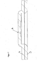
- FIGS. 6 and 7 is shown in fragmentary form in the form of an enlarged view in a longitudinal section, as the pressing 6 or 6 'by a single punch ( FIG. 7 ) and by a double stamp ( FIG. 6 ) has been realized.
Landscapes
- Engineering & Computer Science (AREA)
- Mechanical Engineering (AREA)
- Architecture (AREA)
- Physics & Mathematics (AREA)
- Electromagnetism (AREA)
- Civil Engineering (AREA)
- Structural Engineering (AREA)
- Rod-Shaped Construction Members (AREA)
Description
- Die Erfindung betrifft einen Metallträger für eine Deckenunterkonstruktion mit einem T-Profil aus einem Doppelblech, wobei sich der Metallträger durch die Merkmale des kennzeichnenden Teils des Anspruchs 1 auszeichnet. Die Erfindung betrifft weiterhin die Verwendung eines derartigen Metallträgers für metallische Deckenunterkonstruktionen als Haupt- und/oder Querträger, wobei der Flansch in Richtung des Rauminneren zeigt.
- Metallträger der gattungsgemäßen Art für Deckenunterkonstruktionen sind im Stand der Technik bekannt. So beschreibt die
GB 2 456 328 A 2 456 328 A - Weiterhin ist aus der
US 6,199,343 B1 ein Metallträger für eine Deckenunterkonstruktion bekannt, der ebenfalls in Form eines T-Profils ausgebildet ist. Bei den dort gezeigten Ausführungsformen des Metallträgers ist vorgesehen, dass im Stegbereich Einpressungen 55, sog. "Stitchings", angeordnet sind. Das "Stitching" wird durch Einpressen eines Stempels von einer Seite in Richtung der anderen Seite erreicht, so dass ein einseitiges "Stitching" resultiert. -
GB 2 274 080 A - Es hat sich nun gezeigt, dass sowohl das einseitige "Stitching", wie es in der
US 6,199,343 B1 vorgeschlagen wird, als auch das Vorsehen von Hohlprofilen nach derGB 2 456 328 A - Ausgehend hiervon ist es daher die Aufgabe der vorliegenden Erfindung, einen Metallträger vorzuschlagen, der derart ausgebildet ist, dass er auch einem Feuerwiderstand bis maximal 1200 °C (nach DIN-EN 1363 Teil 1) ohne wesentlichen Verzug standhält.
- Diese Aufgabe wird durch die kennzeichnenden Merkmale des Patentanspruches 1 gelöst. Die Unteransprüche zeigen vorteilhafte Weiterbildungen auf.
- Erfindungsgemäß wird somit vorgeschlagen, den Metallträger im Stegbereich mit Verstärkungsrippen ("Stitching") zu versehen, wobei die Verstärkungsrippensowohl ausgehend von der Außenseite des ersten Bleches in Richtung des zweiten Bleches als auch von der Außenseite des zweiten Bleches in Richtung des ersten Bleches eingepresst worden sind. Kern der Erfindung ist somit ein "doppelseitiges Stitching".
- Dadurch, dass nun die Verstärkungsrippen nicht nur von einer Seite in den Stegbereich eingepresst worden sind, sondern von zwei Seiten, kommt es dazu, dass der Metallträger auch unter extremen Bedingungen, wie bei einem Feuerwiderstand von bis zu 1200 °C, keinen Verzug zeigen. Durch das "doppelseitige Stitching" wird offensichtlich das Gefüge des Metallträgers im Stegbereich so positiv beeinflusst, dass sich nicht die aus dem Stand der Technik bekannten Nachteile in Bezug auf den Verzug und die Versteifungsfestigkeit einstellen.
- Bevorzugt ist der Metallträger dabei so ausgebildet, dass die eingepressten Verstärkungsrippen ("Stitching") parallel zum Flansch in Linienform, bevorzugt über die gesamte Länge des Metallträgers, eingepresst sind. Die Erfindung umfasst hierbei Ausführungsformen, bei denen die Einpressungen jeweils abwechselnd, d.h. von einer Seite und der anderen Seite, eingepresst sind, wie auch Ausführungsformen, bei denen mehrere Einpressungen nacheinander von einer Seite und dann wiederum mehrere Einpressungen nacheinander von der anderen Seite vorliegen. Besonders bevorzugt ist es dabei, wenn die Verstärkungsrippen in Linienform jeweils abwechselnd, d.h. eine Einpressung von der Außenseite des ersten Bleches in Richtung des zweiten Bleches, und dann die nächste Einpressung von der anderen Seite des Bleches eingebracht sind. Die Abstände zwischen den Verpressungen können auch variabel sein.
- Eine weitere bevorzugte Ausführungsform sieht dann vor, dass die Verstärkungsrippen in zwei oder drei parallel zum Flansch angeordneten Linien eingepresst sind. Innerhalb der jeweiligen parallel angeordneten Linien mit den Einpressungen ("Stitching") kann die Anzahl der Einpressungen, die von der ersten Seite in Richtung der zweiten Seite und umgekehrt eingepresst sind, variieren.
- Die Erfindung umfasst selbstverständlich auch Ausführungsformen, in der Weise, dass die Verstärkungsrippen in Linienform von der Außenseite eines der Bleche ausgehend eingepresst und parallel in einer hierzu angeordneten zweiten Linie von der Außenseite des anderen Bleches ausgehend eingepresst sind. Für diese Ausführungsform kann auch vorgesehen sein, dass die Verstärkungsrippen der beiden Linien auf Lücke angeordnet sind, d.h. die eine Einpressung, die von der einen Seite in Richtung des anderen Bleches eingepresst ist, ist versetzt zur anderen Einpressung, die von der anderen Seite aus eingebracht worden ist, angeordnet.
- Bei dem Metallträger der Erfindung ist es dabei bevorzugt, wenn die eingepressten Verstärkungsrippen parallel zum Flansch in Linienform im flanschnahen Bereich angeordnet sind.
- Eine weitere bevorzugte Ausführungsform sieht dann vor, dass parallel hierzu Verstärkungsrippen in einer zweiten Linie vorgesehen sind, wobei diese Verstärkungsrippen dann am stegseitigen Ende vorgesehen sind.
- Die Einpressungen sind dabei bevorzugt im letzten Drittel des Stegbereiches vorgesehen. Das beidseitige "Stitching" kann auch nicht in Linienform, sondern über die Flächen des Stegbereichs verteilt vorliegen. Auch für diese Ausführungsform ist die Anzahl der Einpressungen variabel.
- Die Verstärkungsrippen werden durch einen zweistufigen Prozess in den Steg eingebracht. Im ersten Prozessschritt wird dabei eine Lasche aus dem Material freigeschnitten. Im zweiten Prozessschritt erfolgt dann durch einen Stempel ein Verpressen, so dass ein Fließen des Materials der Lasche erfolgt. Durch dieses Verpressen wird dann sichergestellt, dass die Lasche nicht wieder zurück in die Aussparung gedrückt werden kann.
- Die Erfindung umfasst selbstverständlich auch Ausführungsformen, bei denen die Verpressung durch einen einstufigen Prozess hergestellt wird, d.h. in einem Arbeitsgang wird die Lasche freigeschnitten und verpresst.
- Die Verpressung wird dabei durch einen Einfachstempel oder auch durch einen Doppelstempel in Rechteckform hergestellt. Die langen Seiten des Rechtecks liegen im Bereich von 2 bis 8 mm und die kurzen Seiten sind 0,1 bis 1,5 mm lang.
- Zur weiteren Verbesserung der Versteifungsfähigkeit und zur Verbesserung des Verzugs ist in dem erfindungsgemäßen Metallträger noch vorgesehen, dass zusätzlich zum beidseitigen "Stitching" noch ein linienförmiges Verstärkungsprofil vorgesehen ist. Dieses linienförmige Verstärkungsprofil kann dabei als Hohlprofil durch die beiden Doppelbleche gebildet werden und ist bevorzugt parallel zum linienförmigen "Stitching" angeordnet. Eine bevorzugte Aüsführungsform sieht dabei vor, dass das linienförmige Verstärkungsprofil zwischen zwei linienförmigen Verpressungen angeordnet ist.
- Die Metallträger nach der Erfindung können zusätzlich, wie an und für sich aus dem Stand der Technik bekannt, noch Öffnungen aufweisen, die zum Verrasten der Metallträger untereinander vorgesehen sind. Die Metallträger nach der Erfindung können dann auch noch Konnektoren, die stirnseitig an den jeweiligen Enden der Metallträger angeordnet sind, aufweisen, die dazu vorgesehen sind, die Metallträger untereinander durch die Öffnung zu verrasten.
- Bei den erfindungsgemäßen Metallträgern kann es sich dabei um Metallträger einer Länge von 50 bis 400 cm handeln, und zwar je nach Anwendungsfall. Derartige Metallträger können für Deckenunterkonstruktionen angewendet werden, wobei diese dann entweder als Haupt- oder als Querträger fungieren. Die Auswahl der Länge der Metallträger richtet sich dabei selbstverständlich nach dem Anwendungsfall, d.h. danach, ob es sich um einen Haupt- oder um einen Querträger handelt. Das T-Profil der Metallträger weist dabei bevorzugt eine Steghöhe im Stegbereich zwischen 1 und 8 cm auf.
- Das Material der metallischen Träger ist bevorzugt ein Stahlfeinblech aus einem kaltgewalzten Band. Die Stahlsorten umfassen integrierte C-Stähle mit Kohlenstoffmasseanteilen bis zu 1 %, ein bevorzugtes Stahlfeinblech ist DX 51 Z 100.
- Der erfindungsgemäße Metallträger ist wie vorstehend erläutert besonders geeignet für metallische Deckenunterkonstruktionen als Haupt- und/oder Querträger, wobei der Flansch in Richtung des Rauminneren zeigt.
- Die Erfindung wird nachfolgend anhand von sieben Figuren näher erläutert, ohne den Gegenstand auf diese Ausführungsformen zu begrenzen.
-
Figur 1 zeigt im Querschnitt einen Metallträger mit einem zweiseitigen Stitching in zwei Linien. -
Figur 2 zeigt ein weiteres Beispiel, bei der die Einpressungen in der zweiten Linie nur von einer Seite aus durchgeführt worden sind. -
Figur 3 zeigt einen erfindungsgemäßen Metallträgen, mit einem Hohlprofil. -
Figur 4 zeigt in perspektivischer Ansicht einen Metallträger mit einem beidseitigen Stitching in einer Linie. -
Figur 5 zeigt ebenfalls in perspektivischer Darstellung einen Metallträger mit einem Stitching in zwei Linien. -
Figur 6 zeigt im Längsschnitt in vergrößerter Darstellung eine Verpressung, die mit einem Doppelstempel hergestellt worden ist. -
Figur 7 zeigt ebenfalls in vergrößerter Darstellung ausschnittsweise im Längsschnitt eine Verpressung die mit einem Einfachstempel realisiert worden ist. - In
Figur 1 ist im Querschnitt ein Metallträger 1 in Form eines inversen T-Profils dargestellt. Der Metallträger nachFigur 1 ist aus einem Doppelblech 3, 4 gebildet und weist an seinem stegseitigen Ende ein Hohlprofil 5 auf, das durch die beiden Doppelbleche geformt worden ist. InFigur 1 ist nun im Querschnitt zu erkennen, dass die Einpressungen (Stitching) 6, 6' von beiden Seiten in den Stegbereich 2 des Metallträgers 1 eingebracht worden sind. Im Beispielsfall nach derFigur 1 ist am flanschseitigen Ende eine erste Linienform gebildet worden, wobei hier die Einpressungen 6 von der einen Seite, d.h. von der Außenseite des Bleches 3, eingebracht worden sind, wohingegen die Einpressungen 6' von der Außenseite des Bleches 4 eingepresst worden sind. Gleiches gilt für die Einpressungen, die am stegseitigen Ende unterhalb des Hohlprofils 5 vorgesehen sind. Die Ausführungsform nachFigur 1 weist somit ein beidseitiges Stitching auf, wobei jeweils zwei Linien mit abwechselnden Einpressungen vorgesehen sind. - Das Beispiel nach
Figur 2 entspricht nun derjenigen nachFigur 1 , jedoch sind hier die Einpressungen 6 am stegseitigen Ende nur von einer Seite eingebracht worden, d.h. nur von der Außenseite des Bleches 3. Im Unterschied dazu sind die Einpressungen 6, 6', die am flanschseitigen Ende angeordnet sind, jeweils immer von der Außenseite 3 (Einpressung 6) und von der Außenseite 4 (Einpressung 6') vorgenommen worden. - In
Figur 3 ist nun ein erfindungsgemäßer Metallträger gezeigt, der von dem Beispiel nachFigur 2 ausgeht und sich dadurch unterscheidet, dass zwischen den flanschseitigen linienförmigen Einpressungen und den stegseitigen linienförmigen Einpressungen noch ein Hohlprofil 8, das durch die beiden Bleche 3, 4 gebildet ist, angeordnet ist. Dadurch wird eine weitere Verbesserung der Steifigkeit und des Verzugs erreicht. - In
Figur 4 ist nun in perspektivischer Darstellung ein Metallträger 1 dargestellt, der verdeutlicht, dass die Einpressungen 6, 6' in Linienform und dabei abwechselnd am flanschseitigen Ende des Stegbereiches 2 ausgebildet sind. Die Einpressungen 6 und die Einpressungen 6' sind in der Figur dadurch deutlich gemacht, dass die Einpressungen 6` dunkel dargestellt sind, wobei es sich hier um eine Einpressung handelt, die von der dargestellten Seite in Richtung der anderen Seite geführt worden ist. Die Einpressung 6 ist hingegen von der nicht sichtbaren Seite in die dargestellte Seite vorgenommen worden. An dieser Stelle ist auch noch zu betonen, dass die Erfindung selbstverständlich alle Ausführungsformen umfasst, bei denen z.B. dann zwei oder auch drei Einpressungen in die gleiche Richtung vorgenommen worden sind und dann zwei oder drei Einpressungen von der anderen Seite ausgeführt worden sind. Auch ist es nicht erforderlich, dass jeweils immer die gleiche Anzahl von Einpressungen (Stitchings) von jeder Seite vorhanden ist, sondern die Erfindung umfasst auch Ausführungsformen, bei denen z.B. in einer Linie nur 20 % oder 30 % der Einpressungen in eine Richtung vorgenommen worden sind und entsprechend 80 % oder 70 % der Einpressungen von der anderen Richtung. - In
Figur 5 ist nun wiederum in perspektivischer Darstellung ein Metallträger 1 dargestellt, bei dem die Einpressungen 6, 6` in zwei Linien ausgeführt sind, und zwar einerseits in einer ersten Linie, die flanschseitig ausgebildet ist, und in einer zweiten Linie, die am stegseitigen Ende vorgesehen ist. Die perspektivische Darstellung des Metallträgers nachFigur 5 entspricht der Darstellung des Metallträgers im Querschnitt nachFigur 1 . Aus der Darstellung nachFigur 5 wird auch deutlich, dass die Abstände der jeweiligen Einpressungen beliebig gewählt werden können. Im Beispiel nach derFigur 5 sind zwischen den Einpressungen, die am stegseitigen Ende unterhalb des Hohlprofils 5 vorgesehen sind, wesentlich größere Abstände vorgesehen als für die Einpressungen, die am flanschseitigen Ende angeordnet sind. Auch können die Abstände derartiger Einpressungen innerhalb einer Linie variieren. - In den
Figuren 6 und7 ist in Form einer vergrößerten Darstellung in einem Längsschnitt ausschnittsweise gezeigt, wie die Verpressung 6 bzw. 6' durch einen Einfachstempel (Figur 7 ) und durch einen Zweifachstempel (Figur 6 ) realisiert worden ist.
Claims (14)
- Metallträger (1) für eine Deckenunterkonstruktion mit einem T-Profil aus einem Doppelblech, wobei im Stegbereich (2) ein erstes Blech (3) flächig aneinanderliegend zu einem zweiten Blech (4) angeordnet ist, und am stegseitigen Ende aus dem Doppelblech ein Hohlprofil (5) gebildet ist, wobei
im Stegbereich (2) eingepresste Verstärkungsrippen (6, 6') angeordnet sind, wobei die Verstärkungsrippen (6, 6') durch freigeschnittene, verpresste Laschen gebildet sind und eine Rechteckform aufweisen dadurch gekennzeichnet, dass die Verstärkungsrippen (6, 6') ausgehend von der Außenseite des ersten Blechs (3) in Richtung des zweiten Blechs (4) und von der Außenseite des zweiten Blechs (4) in Richtung des ersten Blechs (3) eingepresst sind, wobei die lange Seite des Rechtecks 2 bis 8 mm und die kurze Seite 0,1 bis 1,5 mm beträgt, und dass zusätzlich im Stegbereich (2) bevorzugt über die gesamte Länge des Steges (2) mindestens ein linienförmiges Verstärkungsprofil (8) vorhanden ist. - Metallträger nach Anspruch 1, dadurch gekennzeichnet, dass die eingepressten Verstärkungsrippen (6, 6') parallel zum Flansch (7) in Linienform, bevorzugt über die gesamte Länge des Metallträgers (1), eingepresst sind.
- Metallträger nach Anspruch 2, dadurch gekennzeichnet, dass die Verstärkungsrippen (6, 6') in Linienform abwechselnd von der Außenseite des ersten Bleches (3) und der Außenseite des zweiten Blechs (4) eingepresst sind.
- Metallträger nach Anspruch 2 oder 3, dadurch gekennzeichnet, dass die Verstärkungsrippen (6, 6`) in zwei oder drei parallel zum Flansch (7) angeordneten Linien eingepresst sind.
- Metallträger nach einem der Ansprüche 1 oder 2, dadurch gekennzeichnet, dass die Verstärkungsrippen (6, 6') in Linienform von der Außenseite eines der Bleche (3, 4) ausgehend eingepresst sind und parallel mindestens in einer hierzu angeordneten zweiten Linie die Verstärkungsrippen (6, 6') von der Außenseite des anderen Blechs (3, 4) ausgehend eingepresst sind.
- Metallträger nach Anspruch 5, dadurch gekennzeichnet, dass die Verstärkungsrippen (6, 6`) der beiden Linien auf Lücke angeordnet sind.
- Metallträger nach mindestens einem der Ansprüche 1 bis 6, dadurch gekennzeichnet, dass die Verpressungen (6, 6') durch einen Einfachstempel und/oder durch einen Doppelstempel bevorzugt in Rechteckform hergestellt sind.
- Metallträger nach einem der vorhergehenden Ansprüche, dadurch gekennzeichnet, dass das Verstärkungsprofil (8) als Hohlprofil durch die beiden Doppelbleche (3, 4) gebildet ist.
- Metallträger nach mindestens einem der Ansprüche 1 bis 8, dadurch gekennzeichnet, dass der Flansch (7) aus den Einzelblechen besteht und über ein zusätzliches metallisches Abschlussblech verstärkt ist.
- Metallträger nach mindestens einem der Ansprüche 1 bis 9, dadurch gekennzeichnet dass das stegseitige Ende der T-Träger ein Hohlprofil in Rechteckform ist.
- Metallträger nach mindestens einem der Ansprüche 1 bis 10, dadurch gekennzeichnet, dass der Metallträger (1) eine Länge von 50 bis 400 cm und das T-Profil der Metallträger (1) eine Steghöhe des Stegbereichs (2) von 1 bis 8 cm aufweist.
- Metallträger nach mindestens einem der Ansprüche 1 bis 11, dadurch gekennzeichnet, dass das metallische Material des Trägers (1) ein Stahlfeinblech ist.
- Metallträger nach mindestens einem der Ansprüche 1 bis 12, dadurch gekennzeichnet, dass im Stegbereich (2) des Metallträgers (1) Öffnungen vorgesehen sind, durch die an den stirnseitigen Enden der Metallträger (1) angeordnete Konnektoren führbar sind, die zur Verrastung mit Konnektoren der anderen Metallträger (1) dienen.
- Verwendung der Metallträger nach mindestens einem der Ansprüche 1 bis 13 für metallische Deckenunterkonstruktionen als Haupt-und/oder Querträger, wobei der Flansch in Richtung des Rauminneren zeigt.
Priority Applications (3)
| Application Number | Priority Date | Filing Date | Title |
|---|---|---|---|
| PL11004788T PL2532799T3 (pl) | 2011-06-10 | 2011-06-10 | Dźwigar metalowy i jego wykorzystanie |
| ES11004788.3T ES2539916T3 (es) | 2011-06-10 | 2011-06-10 | Viga metálica y su utilización |
| EP20110004788 EP2532799B1 (de) | 2011-06-10 | 2011-06-10 | Metallträger und dessen Verwendung |
Applications Claiming Priority (1)
| Application Number | Priority Date | Filing Date | Title |
|---|---|---|---|
| EP20110004788 EP2532799B1 (de) | 2011-06-10 | 2011-06-10 | Metallträger und dessen Verwendung |
Publications (2)
| Publication Number | Publication Date |
|---|---|
| EP2532799A1 EP2532799A1 (de) | 2012-12-12 |
| EP2532799B1 true EP2532799B1 (de) | 2015-05-20 |
Family
ID=44652095
Family Applications (1)
| Application Number | Title | Priority Date | Filing Date |
|---|---|---|---|
| EP20110004788 Active EP2532799B1 (de) | 2011-06-10 | 2011-06-10 | Metallträger und dessen Verwendung |
Country Status (3)
| Country | Link |
|---|---|
| EP (1) | EP2532799B1 (de) |
| ES (1) | ES2539916T3 (de) |
| PL (1) | PL2532799T3 (de) |
Families Citing this family (3)
| Publication number | Priority date | Publication date | Assignee | Title |
|---|---|---|---|---|
| DK2877643T3 (en) * | 2012-07-27 | 2016-08-22 | Giuseppe Cipriani | Beam for a supporting structure for a suspended ceiling as well as a manufacturing process for the manufacture of the beam |
| ITVR20130040A1 (it) | 2013-02-14 | 2014-08-15 | Giuseppe Cipriani | Struttura metallica di supporto di un controsoffitto. |
| ITVR20130058A1 (it) | 2013-03-08 | 2014-09-09 | Giuseppe Cipriani | Profilato di una struttura di supporto di un controsoffitto e procedimento di lavorazione per lavorare il profilato. |
Citations (1)
| Publication number | Priority date | Publication date | Assignee | Title |
|---|---|---|---|---|
| GB2274080A (en) * | 1993-01-08 | 1994-07-13 | Armstrong World Ind Inc | Improved rollformed sections and process for producing same |
Family Cites Families (8)
| Publication number | Priority date | Publication date | Assignee | Title |
|---|---|---|---|---|
| GB1050146A (de) * | ||||
| US5044138A (en) * | 1989-10-13 | 1991-09-03 | Usg Interiors, Inc. | Ceiling suspension structure adapted for unopposed intersections |
| DE4431849A1 (de) * | 1994-09-07 | 1996-03-14 | Nagel Hans Joachim | Durchsetz-Fügeverfahren und Durchsetz-Fügewerkzeug |
| US6199343B1 (en) | 1999-04-19 | 2001-03-13 | Worthington Armstrong Venture | Connector assembly for ceiling grid |
| US6523314B1 (en) * | 2000-12-29 | 2003-02-25 | Usg Interiors, Inc. | Ceiling grid with resilient centering tabs |
| ITVE20050046A1 (it) * | 2005-10-03 | 2007-04-04 | Dallan Spa | Procedimento di aggraffiatura di profilati a t, apparecchiatura per attuare il procedimento e profilato ottenuto con il procedimento.- |
| US7669374B2 (en) * | 2007-04-03 | 2010-03-02 | Worthington Armstrong Venture | Beam for a drywall ceiling soffit |
| GB2456328A (en) | 2008-01-11 | 2009-07-15 | Usg Interiors Inc | Grid members for a suspended ceiling and methods of making same |
-
2011
- 2011-06-10 EP EP20110004788 patent/EP2532799B1/de active Active
- 2011-06-10 ES ES11004788.3T patent/ES2539916T3/es active Active
- 2011-06-10 PL PL11004788T patent/PL2532799T3/pl unknown
Patent Citations (1)
| Publication number | Priority date | Publication date | Assignee | Title |
|---|---|---|---|---|
| GB2274080A (en) * | 1993-01-08 | 1994-07-13 | Armstrong World Ind Inc | Improved rollformed sections and process for producing same |
Also Published As
| Publication number | Publication date |
|---|---|
| PL2532799T3 (pl) | 2015-11-30 |
| ES2539916T3 (es) | 2015-07-07 |
| EP2532799A1 (de) | 2012-12-12 |
Similar Documents
| Publication | Publication Date | Title |
|---|---|---|
| EP0531869B1 (de) | Montageklemme | |
| EP2813783A1 (de) | Ständer zum Abstützen von Solarpaneelen auf einem Flachdach | |
| CH704363A1 (de) | Verbundprofil für Fenster, Türen und Fassaden sowie Verfahren zu dessen Herstellung. | |
| DE202012104033U1 (de) | Haltevorrichtung für eine Brüstungs- oder Geländerplatte sowie Geländer oder Brüstung mit Scheibe | |
| DE202005006528U1 (de) | Befestigungsprofil | |
| EP2532799A1 (de) | Metallträger und dessen Verwendung | |
| EP2625346B1 (de) | Metallische deckenunterkonstruktion | |
| DE3705356A1 (de) | Schalungsplatten-traeger fuer betonierungsschalungen | |
| EP1780345A2 (de) | Verbinder für rinnenförmige Profilstäbe und Verbindungsanordnung | |
| AT518435B1 (de) | Beschlagverbund für das Verbinden von länglichen Deckelementen | |
| DE3446091C2 (de) | Profil zum Einfassen der Kanten einer Öffnung | |
| DE202010015534U1 (de) | Dichtung | |
| AT329838B (de) | Gitterrost | |
| DE19609480B4 (de) | Kabelkanaldeckel | |
| DE2843457A1 (de) | Fassadenverkleidung | |
| WO2025016612A1 (de) | Halteelement | |
| AT413878B (de) | Eckverbindung für die abgekanteten wandflansche eines im querschnitt rechtwinkeligen blechkanalschusses | |
| AT16346U1 (de) | Vergrößerbare Platte | |
| EP4459202A1 (de) | Ballastierungssystem | |
| EP4517024A2 (de) | Fassadenunterkonstruktionskonsole | |
| DE202024105398U1 (de) | Kreuzverbinder | |
| WO2004016874A1 (de) | Verbundbetonplatte und halteanker zum verbinden zweier beton-platten | |
| DE102022200760A1 (de) | Flachformfeder | |
| DE202006015548U1 (de) | Gitterrost-Trittstufe | |
| CH716765B1 (de) | Trägerelement mit in Ausnehmungen eines Holzträgers aufgenommenen Spannprofilen zur Erzeugung einer Überhöhung. |
Legal Events
| Date | Code | Title | Description |
|---|---|---|---|
| PUAI | Public reference made under article 153(3) epc to a published international application that has entered the european phase |
Free format text: ORIGINAL CODE: 0009012 |
|
| AK | Designated contracting states |
Kind code of ref document: A1 Designated state(s): AL AT BE BG CH CY CZ DE DK EE ES FI FR GB GR HR HU IE IS IT LI LT LU LV MC MK MT NL NO PL PT RO RS SE SI SK SM TR |
|
| AX | Request for extension of the european patent |
Extension state: BA ME |
|
| 17P | Request for examination filed |
Effective date: 20130611 |
|
| RBV | Designated contracting states (corrected) |
Designated state(s): AL AT BE BG CH CY CZ DE DK EE ES FI FR GB GR HR HU IE IS IT LI LT LU LV MC MK MT NL NO PL PT RO RS SE SI SK SM TR |
|
| 17Q | First examination report despatched |
Effective date: 20130703 |
|
| REG | Reference to a national code |
Ref country code: DE Ref legal event code: R079 Ref document number: 502011006853 Country of ref document: DE Free format text: PREVIOUS MAIN CLASS: E04B0009060000 Ipc: B21D0039030000 |
|
| GRAP | Despatch of communication of intention to grant a patent |
Free format text: ORIGINAL CODE: EPIDOSNIGR1 |
|
| RIC1 | Information provided on ipc code assigned before grant |
Ipc: B21D 47/01 20060101ALI20141117BHEP Ipc: B21D 39/03 20060101AFI20141117BHEP |
|
| INTG | Intention to grant announced |
Effective date: 20141202 |
|
| GRAS | Grant fee paid |
Free format text: ORIGINAL CODE: EPIDOSNIGR3 |
|
| GRAA | (expected) grant |
Free format text: ORIGINAL CODE: 0009210 |
|
| AK | Designated contracting states |
Kind code of ref document: B1 Designated state(s): AL AT BE BG CH CY CZ DE DK EE ES FI FR GB GR HR HU IE IS IT LI LT LU LV MC MK MT NL NO PL PT RO RS SE SI SK SM TR |
|
| REG | Reference to a national code |
Ref country code: GB Ref legal event code: FG4D Free format text: NOT ENGLISH |
|
| REG | Reference to a national code |
Ref country code: CH Ref legal event code: EP |
|
| REG | Reference to a national code |
Ref country code: AT Ref legal event code: REF Ref document number: 727466 Country of ref document: AT Kind code of ref document: T Effective date: 20150615 |
|
| REG | Reference to a national code |
Ref country code: IE Ref legal event code: FG4D Free format text: LANGUAGE OF EP DOCUMENT: GERMAN |
|
| REG | Reference to a national code |
Ref country code: DE Ref legal event code: R096 Ref document number: 502011006853 Country of ref document: DE Effective date: 20150702 |
|
| REG | Reference to a national code |
Ref country code: ES Ref legal event code: FG2A Ref document number: 2539916 Country of ref document: ES Kind code of ref document: T3 Effective date: 20150707 |
|
| REG | Reference to a national code |
Ref country code: FR Ref legal event code: PLFP Year of fee payment: 5 |
|
| REG | Reference to a national code |
Ref country code: LT Ref legal event code: MG4D |
|
| REG | Reference to a national code |
Ref country code: NL Ref legal event code: MP Effective date: 20150520 |
|
| PG25 | Lapsed in a contracting state [announced via postgrant information from national office to epo] |
Ref country code: FI Free format text: LAPSE BECAUSE OF FAILURE TO SUBMIT A TRANSLATION OF THE DESCRIPTION OR TO PAY THE FEE WITHIN THE PRESCRIBED TIME-LIMIT Effective date: 20150520 Ref country code: LT Free format text: LAPSE BECAUSE OF FAILURE TO SUBMIT A TRANSLATION OF THE DESCRIPTION OR TO PAY THE FEE WITHIN THE PRESCRIBED TIME-LIMIT Effective date: 20150520 Ref country code: PT Free format text: LAPSE BECAUSE OF FAILURE TO SUBMIT A TRANSLATION OF THE DESCRIPTION OR TO PAY THE FEE WITHIN THE PRESCRIBED TIME-LIMIT Effective date: 20150921 Ref country code: HR Free format text: LAPSE BECAUSE OF FAILURE TO SUBMIT A TRANSLATION OF THE DESCRIPTION OR TO PAY THE FEE WITHIN THE PRESCRIBED TIME-LIMIT Effective date: 20150520 Ref country code: NO Free format text: LAPSE BECAUSE OF FAILURE TO SUBMIT A TRANSLATION OF THE DESCRIPTION OR TO PAY THE FEE WITHIN THE PRESCRIBED TIME-LIMIT Effective date: 20150820 |
|
| PG25 | Lapsed in a contracting state [announced via postgrant information from national office to epo] |
Ref country code: IS Free format text: LAPSE BECAUSE OF FAILURE TO SUBMIT A TRANSLATION OF THE DESCRIPTION OR TO PAY THE FEE WITHIN THE PRESCRIBED TIME-LIMIT Effective date: 20150920 Ref country code: BG Free format text: LAPSE BECAUSE OF FAILURE TO SUBMIT A TRANSLATION OF THE DESCRIPTION OR TO PAY THE FEE WITHIN THE PRESCRIBED TIME-LIMIT Effective date: 20150820 Ref country code: RS Free format text: LAPSE BECAUSE OF FAILURE TO SUBMIT A TRANSLATION OF THE DESCRIPTION OR TO PAY THE FEE WITHIN THE PRESCRIBED TIME-LIMIT Effective date: 20150520 Ref country code: GR Free format text: LAPSE BECAUSE OF FAILURE TO SUBMIT A TRANSLATION OF THE DESCRIPTION OR TO PAY THE FEE WITHIN THE PRESCRIBED TIME-LIMIT Effective date: 20150821 Ref country code: LV Free format text: LAPSE BECAUSE OF FAILURE TO SUBMIT A TRANSLATION OF THE DESCRIPTION OR TO PAY THE FEE WITHIN THE PRESCRIBED TIME-LIMIT Effective date: 20150520 |
|
| REG | Reference to a national code |
Ref country code: PL Ref legal event code: T3 |
|
| PG25 | Lapsed in a contracting state [announced via postgrant information from national office to epo] |
Ref country code: EE Free format text: LAPSE BECAUSE OF FAILURE TO SUBMIT A TRANSLATION OF THE DESCRIPTION OR TO PAY THE FEE WITHIN THE PRESCRIBED TIME-LIMIT Effective date: 20150520 Ref country code: DK Free format text: LAPSE BECAUSE OF FAILURE TO SUBMIT A TRANSLATION OF THE DESCRIPTION OR TO PAY THE FEE WITHIN THE PRESCRIBED TIME-LIMIT Effective date: 20150520 |
|
| REG | Reference to a national code |
Ref country code: CH Ref legal event code: PL |
|
| REG | Reference to a national code |
Ref country code: DE Ref legal event code: R097 Ref document number: 502011006853 Country of ref document: DE |
|
| PG25 | Lapsed in a contracting state [announced via postgrant information from national office to epo] |
Ref country code: SK Free format text: LAPSE BECAUSE OF FAILURE TO SUBMIT A TRANSLATION OF THE DESCRIPTION OR TO PAY THE FEE WITHIN THE PRESCRIBED TIME-LIMIT Effective date: 20150520 Ref country code: CZ Free format text: LAPSE BECAUSE OF FAILURE TO SUBMIT A TRANSLATION OF THE DESCRIPTION OR TO PAY THE FEE WITHIN THE PRESCRIBED TIME-LIMIT Effective date: 20150520 Ref country code: MC Free format text: LAPSE BECAUSE OF FAILURE TO SUBMIT A TRANSLATION OF THE DESCRIPTION OR TO PAY THE FEE WITHIN THE PRESCRIBED TIME-LIMIT Effective date: 20150520 Ref country code: RO Free format text: LAPSE BECAUSE OF NON-PAYMENT OF DUE FEES Effective date: 20150520 |
|
| REG | Reference to a national code |
Ref country code: IE Ref legal event code: MM4A |
|
| PLBE | No opposition filed within time limit |
Free format text: ORIGINAL CODE: 0009261 |
|
| STAA | Information on the status of an ep patent application or granted ep patent |
Free format text: STATUS: NO OPPOSITION FILED WITHIN TIME LIMIT |
|
| 26N | No opposition filed |
Effective date: 20160223 |
|
| PG25 | Lapsed in a contracting state [announced via postgrant information from national office to epo] |
Ref country code: LI Free format text: LAPSE BECAUSE OF NON-PAYMENT OF DUE FEES Effective date: 20150630 Ref country code: CH Free format text: LAPSE BECAUSE OF NON-PAYMENT OF DUE FEES Effective date: 20150630 Ref country code: IE Free format text: LAPSE BECAUSE OF NON-PAYMENT OF DUE FEES Effective date: 20150610 |
|
| PG25 | Lapsed in a contracting state [announced via postgrant information from national office to epo] |
Ref country code: SI Free format text: LAPSE BECAUSE OF FAILURE TO SUBMIT A TRANSLATION OF THE DESCRIPTION OR TO PAY THE FEE WITHIN THE PRESCRIBED TIME-LIMIT Effective date: 20150520 |
|
| REG | Reference to a national code |
Ref country code: FR Ref legal event code: PLFP Year of fee payment: 6 |
|
| PG25 | Lapsed in a contracting state [announced via postgrant information from national office to epo] |
Ref country code: MT Free format text: LAPSE BECAUSE OF FAILURE TO SUBMIT A TRANSLATION OF THE DESCRIPTION OR TO PAY THE FEE WITHIN THE PRESCRIBED TIME-LIMIT Effective date: 20150520 |
|
| PG25 | Lapsed in a contracting state [announced via postgrant information from national office to epo] |
Ref country code: HU Free format text: LAPSE BECAUSE OF FAILURE TO SUBMIT A TRANSLATION OF THE DESCRIPTION OR TO PAY THE FEE WITHIN THE PRESCRIBED TIME-LIMIT; INVALID AB INITIO Effective date: 20110610 Ref country code: SM Free format text: LAPSE BECAUSE OF FAILURE TO SUBMIT A TRANSLATION OF THE DESCRIPTION OR TO PAY THE FEE WITHIN THE PRESCRIBED TIME-LIMIT Effective date: 20150520 |
|
| REG | Reference to a national code |
Ref country code: FR Ref legal event code: PLFP Year of fee payment: 7 |
|
| PG25 | Lapsed in a contracting state [announced via postgrant information from national office to epo] |
Ref country code: NL Free format text: LAPSE BECAUSE OF FAILURE TO SUBMIT A TRANSLATION OF THE DESCRIPTION OR TO PAY THE FEE WITHIN THE PRESCRIBED TIME-LIMIT Effective date: 20150520 Ref country code: SE Free format text: LAPSE BECAUSE OF FAILURE TO SUBMIT A TRANSLATION OF THE DESCRIPTION OR TO PAY THE FEE WITHIN THE PRESCRIBED TIME-LIMIT Effective date: 20150520 Ref country code: CY Free format text: LAPSE BECAUSE OF FAILURE TO SUBMIT A TRANSLATION OF THE DESCRIPTION OR TO PAY THE FEE WITHIN THE PRESCRIBED TIME-LIMIT Effective date: 20150520 |
|
| REG | Reference to a national code |
Ref country code: AT Ref legal event code: MM01 Ref document number: 727466 Country of ref document: AT Kind code of ref document: T Effective date: 20160610 |
|
| PG25 | Lapsed in a contracting state [announced via postgrant information from national office to epo] |
Ref country code: AT Free format text: LAPSE BECAUSE OF NON-PAYMENT OF DUE FEES Effective date: 20160610 |
|
| PG25 | Lapsed in a contracting state [announced via postgrant information from national office to epo] |
Ref country code: LU Free format text: LAPSE BECAUSE OF NON-PAYMENT OF DUE FEES Effective date: 20150610 |
|
| REG | Reference to a national code |
Ref country code: FR Ref legal event code: PLFP Year of fee payment: 8 |
|
| PG25 | Lapsed in a contracting state [announced via postgrant information from national office to epo] |
Ref country code: MK Free format text: LAPSE BECAUSE OF FAILURE TO SUBMIT A TRANSLATION OF THE DESCRIPTION OR TO PAY THE FEE WITHIN THE PRESCRIBED TIME-LIMIT Effective date: 20150520 |
|
| PG25 | Lapsed in a contracting state [announced via postgrant information from national office to epo] |
Ref country code: AL Free format text: LAPSE BECAUSE OF FAILURE TO SUBMIT A TRANSLATION OF THE DESCRIPTION OR TO PAY THE FEE WITHIN THE PRESCRIBED TIME-LIMIT Effective date: 20150520 |
|
| P01 | Opt-out of the competence of the unified patent court (upc) registered |
Effective date: 20230822 |
|
| PGFP | Annual fee paid to national office [announced via postgrant information from national office to epo] |
Ref country code: PL Payment date: 20250521 Year of fee payment: 15 Ref country code: DE Payment date: 20250627 Year of fee payment: 15 |
|
| PGFP | Annual fee paid to national office [announced via postgrant information from national office to epo] |
Ref country code: GB Payment date: 20250627 Year of fee payment: 15 |
|
| PGFP | Annual fee paid to national office [announced via postgrant information from national office to epo] |
Ref country code: BE Payment date: 20250627 Year of fee payment: 15 |
|
| PGFP | Annual fee paid to national office [announced via postgrant information from national office to epo] |
Ref country code: FR Payment date: 20250625 Year of fee payment: 15 |
|
| PGFP | Annual fee paid to national office [announced via postgrant information from national office to epo] |
Ref country code: TR Payment date: 20250526 Year of fee payment: 15 |
|
| PGFP | Annual fee paid to national office [announced via postgrant information from national office to epo] |
Ref country code: ES Payment date: 20250701 Year of fee payment: 15 |
|
| PGFP | Annual fee paid to national office [announced via postgrant information from national office to epo] |
Ref country code: IT Payment date: 20250619 Year of fee payment: 15 |