EP2532799B1 - Support métallique et son utilisation - Google Patents
Support métallique et son utilisation Download PDFInfo
- Publication number
- EP2532799B1 EP2532799B1 EP20110004788 EP11004788A EP2532799B1 EP 2532799 B1 EP2532799 B1 EP 2532799B1 EP 20110004788 EP20110004788 EP 20110004788 EP 11004788 A EP11004788 A EP 11004788A EP 2532799 B1 EP2532799 B1 EP 2532799B1
- Authority
- EP
- European Patent Office
- Prior art keywords
- metal
- pressed
- reinforcing ribs
- web
- girder according
- Prior art date
- Legal status (The legal status is an assumption and is not a legal conclusion. Google has not performed a legal analysis and makes no representation as to the accuracy of the status listed.)
- Active
Links
Images




Classifications
-
- E—FIXED CONSTRUCTIONS
- E04—BUILDING
- E04B—GENERAL BUILDING CONSTRUCTIONS; WALLS, e.g. PARTITIONS; ROOFS; FLOORS; CEILINGS; INSULATION OR OTHER PROTECTION OF BUILDINGS
- E04B9/00—Ceilings; Construction of ceilings, e.g. false ceilings; Ceiling construction with regard to insulation
- E04B9/06—Ceilings; Construction of ceilings, e.g. false ceilings; Ceiling construction with regard to insulation characterised by constructional features of the supporting construction, e.g. cross section or material of framework members
- E04B9/065—Ceilings; Construction of ceilings, e.g. false ceilings; Ceiling construction with regard to insulation characterised by constructional features of the supporting construction, e.g. cross section or material of framework members comprising supporting beams having a folded cross-section
- E04B9/067—Ceilings; Construction of ceilings, e.g. false ceilings; Ceiling construction with regard to insulation characterised by constructional features of the supporting construction, e.g. cross section or material of framework members comprising supporting beams having a folded cross-section with inverted T-shaped cross-section
- E04B9/068—Ceilings; Construction of ceilings, e.g. false ceilings; Ceiling construction with regard to insulation characterised by constructional features of the supporting construction, e.g. cross section or material of framework members comprising supporting beams having a folded cross-section with inverted T-shaped cross-section with double web
-
- B—PERFORMING OPERATIONS; TRANSPORTING
- B21—MECHANICAL METAL-WORKING WITHOUT ESSENTIALLY REMOVING MATERIAL; PUNCHING METAL
- B21D—WORKING OR PROCESSING OF SHEET METAL OR METAL TUBES, RODS OR PROFILES WITHOUT ESSENTIALLY REMOVING MATERIAL; PUNCHING METAL
- B21D39/00—Application of procedures in order to connect objects or parts, e.g. coating with sheet metal otherwise than by plating; Tube expanders
- B21D39/03—Application of procedures in order to connect objects or parts, e.g. coating with sheet metal otherwise than by plating; Tube expanders of sheet metal otherwise than by folding
- B21D39/035—Joining superposed plates by slitting
-
- B—PERFORMING OPERATIONS; TRANSPORTING
- B21—MECHANICAL METAL-WORKING WITHOUT ESSENTIALLY REMOVING MATERIAL; PUNCHING METAL
- B21D—WORKING OR PROCESSING OF SHEET METAL OR METAL TUBES, RODS OR PROFILES WITHOUT ESSENTIALLY REMOVING MATERIAL; PUNCHING METAL
- B21D47/00—Making rigid structural elements or units, e.g. honeycomb structures
- B21D47/01—Making rigid structural elements or units, e.g. honeycomb structures beams or pillars
Definitions
- the invention relates to a metal support for a ceiling substructure with a T-profile of a double sheet, wherein the metal support is characterized by the features of the characterizing part of claim 1.
- the invention further relates to the use of such a metal support for metallic ceiling substructures as the main and / or cross member, wherein the flange points in the direction of the interior of the room.
- Metal supports of the generic type for ceiling substructures are known in the art. That's how it describes GB 2 456 328 A a corresponding metal carrier, which is designed in the form of a T-profile is.
- the metal support according to the British application is also formed from a double sheet and has at the web-side end of a hollow profile.
- the linear hollow profiles are formed by the double plate and are present substantially over the entire length of the metal carrier.
- GB 2 274 080 A shows a metal carrier according to the preamble of claim 1.
- the metal carrier in the web area with reinforcing ribs ("stitching"), wherein the reinforcing ribs have been pressed both from the outside of the first sheet in the direction of the second sheet as well as from the outside of the second sheet in the direction of the first sheet ,
- the core of the invention is thus a "double-sided stitching".
- the metal carrier is designed so that the pressed-in reinforcing ribs ("stitching") parallel to the flange in line shape, preferably over the entire length of the metal carrier, are pressed.
- the invention in this case comprises embodiments in which the press-ins are alternately, i. from one side and the other side, as well as embodiments in which there are several pressings successively from one side and then again several pressings in succession from the other side.
- the reinforcing ribs alternate in a line shape in each case, i. an injection from the outside of the first sheet in the direction of the second sheet, and then the next press-in from the other side of the sheet are introduced.
- the distances between the pressings can also be variable.
- a further preferred embodiment then provides that the reinforcing ribs are pressed into two or three lines arranged parallel to the flange. Within the respective parallel lines with the "stitching", the number of impressions that are pressed in from the first side in the direction of the second side and vice versa may vary.
- the invention also includes embodiments in such a way that the reinforcing ribs are pressed in line form starting from the outside of one of the sheets and are pressed in parallel in a second line arranged therefrom, starting from the outside of the other sheet.
- the reinforcing ribs of the two lines are arranged on a gap are, that is, a press-fitting, which is pressed from one side in the direction of the other sheet, is offset from the other press-in, which has been introduced from the other side, arranged.
- the pressed-in reinforcing ribs are arranged parallel to the flange in line form in the vicinity of the flange.
- a further preferred embodiment then provides that reinforcing ribs are provided in a second line parallel thereto, wherein these reinforcing ribs are then provided at the web-side end.
- the impressions are preferably provided in the last third of the web area.
- the two-sided "stitching" can not be distributed in line form, but distributed over the surfaces of the web area. Also for this embodiment, the number of press-in is variable.
- the reinforcing ribs are introduced into the web by a two-step process.
- a tab is cut free from the material.
- the second process step is then carried out by a stamp pressing, so that a flow of the material of the tab takes place. By this pressing is then ensured that the tab can not be pushed back into the recess.
- the invention also includes embodiments in which the compression is produced by a one-step process, i. In one operation, the tab is cut free and pressed.
- the compression is made by a single punch or by a double punch in a rectangular shape.
- the long sides of the rectangle are in the range of 2 to 8 mm and the short sides are 0.1 to 1.5 mm long.
- This linear reinforcing profile can be formed as a hollow profile by the two double sheets and is preferably arranged parallel to the line-shaped "stitching". In this case, a preferred embodiment provides that the linear reinforcing profile is arranged between two line-shaped pressings.
- the metal carriers according to the invention may additionally, as is known per se from the prior art, still have openings which are provided for latching the metal carriers to one another.
- the metal carriers according to the invention may then also have connectors, which are arranged on the front side at the respective ends of the metal carrier, which are provided to lock the metal carrier with each other through the opening.
- the metal carriers according to the invention may be metal carriers of a length of 50 to 400 cm, depending on the application. Such metal beams can be used for ceiling substructures, which then act either as a main or as a cross member.
- the selection of the length of the metal support depends of course on the application, i. depending on whether it is a main or a cross member.
- the T-profile of the metal carrier preferably has a web height in the web region between 1 and 8 cm.
- the material of the metallic supports is preferably a steel sheet of a cold-rolled strip.
- the steel grades include integrated carbon steels with carbon mass fractions up to 1%, a preferred steel sheet is DX 51 Z 100.
- the metal support according to the invention is as described above particularly suitable for metallic ceiling substructures as the main and / or cross member, wherein the flange points in the direction of the interior of the room.
- FIG. 1 is shown in cross section a metal carrier 1 in the form of an inverse T-profile.
- the metal carrier after FIG. 1 is formed of a double sheet 3, 4 and has at its web-end a hollow profile 5, which has been formed by the two double sheets.
- FIG. 1 is now seen in cross-section that the pressings (stitching) 6, 6 'have been introduced from both sides in the web portion 2 of the metal carrier 1.
- a first line shape has been formed at the flange end, in which case the press-in 6 from one side, ie from the outside of the sheet 3, have been introduced, whereas the press-in 6 'have been pressed from the outside of the sheet 4.
- the embodiment according to FIG. 1 thus has a double-sided stitching, each with two lines are provided with alternating pressings.
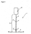
- FIG. 2 now corresponds to the one after FIG. 1
- the indentations 6 have been introduced at the web-side end only from one side, ie only from the outside of the sheet 3.
- the indentations 6, 6 ' which are arranged at the flange end, always from the outer side. 3 (Press 6) and from the outside 4 (press 6 ') have been made.
- FIG. 3 Now, a metal carrier according to the invention is shown, which by the example FIG. 2 emanating and differs in that between the flange-side line-shaped press-in and the web-side linear press-in nor a hollow section 8, which is formed by the two sheets 3, 4, is arranged. This achieves a further improvement in rigidity and distortion.
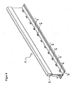
- FIG. 4 is now a perspective view of a metal support 1, which illustrates that the press-in 6, 6 'in line form and thereby alternately formed at the flange-side end of the web portion 2.
- the press-6 has been made from the non-visible page in the page shown.
- the invention of course includes all embodiments in which, for example, then two or three pressings have been made in the same direction and then two or three pressings have been carried out from the other side.
- the invention also includes embodiments in which, for example, in one line only 20% or 30% of the impressions have been made in one direction and correspondingly 80% or 70% of the impressions from the other direction.
- FIG. 5 is now in turn a perspective view of a metal support 1 shown, in which the press-in 6, 6 'are executed in two lines, on the one hand in a first line, which is formed on the flange side, and in a second line, which is provided at the web-side end ,
- the perspective view of the metal carrier after FIG. 5 corresponds to the representation of the metal carrier in cross section FIG. 1 , From the illustration to FIG. 5 It is also clear that the distances of the respective impressions can be chosen arbitrarily. In the example after the FIG. 5 are provided between the press-in, which are provided at the web-side end below the hollow section 5, much greater distances than for the press-in, the flange-side end are arranged. Also, the distances of such impressions may vary within a line.
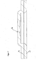
- FIGS. 6 and 7 is shown in fragmentary form in the form of an enlarged view in a longitudinal section, as the pressing 6 or 6 'by a single punch ( FIG. 7 ) and by a double stamp ( FIG. 6 ) has been realized.
Landscapes
- Engineering & Computer Science (AREA)
- Mechanical Engineering (AREA)
- Architecture (AREA)
- Physics & Mathematics (AREA)
- Electromagnetism (AREA)
- Civil Engineering (AREA)
- Structural Engineering (AREA)
- Rod-Shaped Construction Members (AREA)
Claims (14)
- Poutre métallique (1) pour une ossature de plafond, ayant un profil en T réalisé dans une double tôle, dans la zone de l'âme (2) une première tôle (3) étant disposée à plat contre une deuxième tôle (4), et un profil creux (5) étant formé à partir de la double tôle au niveau de l'extrémité de l'âme, des raidisseurs (6, 6') enfoncés étant disposés dans la zone de l'âme (2), lesdits raidisseurs (6, 6') étant formés par des pattes dégagées, serties et ayant une forme rectangulaire,
caractérisée en ce que les raidisseurs (6, 6') sont enfoncés à partir de la face extérieure de la première tôle (3) vers la deuxième tôle (4) et à partir de la face extérieure de la deuxième tôle (4) vers la première tôle (3), le grand côté du rectangle mesurant 2 à 8 mm et le petit côté mesurant 0,1 à 1,5 mm, et en ce que, en plus, au moins un profil de raidissement (8) rectiligne est disposé dans la zone de l'âme (2) de préférence sur toute la longueur de la zone de l'âme (2). - Poutre métallique selon la revendication 1, caractérisée en ce que les raidisseurs (6, 6') sont enfoncés en ligne parallèlement à la semelle (7), de préférence sur toute la longueur de la poutre métallique (1).
- Poutre métallique selon la revendication 2, caractérisée en ce que les raidisseurs (6, 6') sont enfoncés en ligne alternativement à partir de la face extérieure de la première tôle (3) et à partir de la face extérieure de la deuxième tôle (4).
- Poutre métallique selon la revendication 2 ou 3, caractérisée en ce que les raidisseurs (6, 6') sont enfoncés en deux ou trois lignes disposées parallèlement à la semelle (7).
- Poutre métallique selon la revendication 1 ou 2, caractérisée en ce que les raidisseurs (6, 6') sont enfoncés en ligne à partir de la face extérieure d'une des tôles (3, 4) et les raidisseurs (6, 6') sont enfoncés parallèlement en formant au moins une deuxième ligne, à partir de la face extérieure de l'autre tôle (3, 4).
- Poutre métallique selon la revendication 5, caractérisée en ce que les raidisseurs (6, 6') dans les deux lignes sont disposés à distance les uns des autres.
- Poutre métallique selon au moins l'une quelconque des revendications 1 à 6, caractérisée en ce que les sertissages (6, 6') sont réalisés par un poinçon simple et/ou par un poinçon double, de préférence sous forme de rectangle.
- Poutre métallique selon l'une quelconque des revendications précédentes, caractérisée en ce que le profil de raidissement (8) est un profil creux formé par les deux doubles tôles (3, 4).
- Poutre métallique selon au moins l'une quelconque des revendications 1 à 8, caractérisée en ce que la semelle (7) est réalisé en tôles individuelles et est renforcée par une tôle de terminaison métallique supplémentaire.
- Poutre métallique selon au moins l'une quelconque des revendications 1 à 9, caractérisée en ce que l'extrémité du côté âme de la poutre en T comporte un profil creux en forme de rectangle.
- Poutre métallique selon au moins l'une quelconque des revendications 1 à 10, caractérisée en ce que la poutre métallique (1) a une longueur de 50 à 400 cm et le profil en T de la poutre métallique (1) a une hauteur d'âme dans la zone de l'âme (2) de 1 à 8 cm.
- Poutre métallique selon au moins l'une quelconque des revendications 1 à 11, caractérisée en ce que le matériau métallique de la poutre (1) est une tôle fine en acier.
- Poutre métallique selon au moins l'une quelconque des revendications 1 à 12, caractérisée en ce que dans la zone de l'âme (2) de la poutre métallique (1) sont prévues des ouvertures, à travers lesquelles peuvent passer des connecteurs, disposés aux extrémités frontales de la poutre métallique (1), lesquels sont utilisés pour être connectés à des connecteurs des autres poutres métalliques (1).
- Utilisation des poutres métalliques selon au moins l'une des revendications 1 à 13 pour des ossatures métalliques de plafond en tant que poutres maîtresses et/ou poutres transversales, la semelle étant orientée en direction de l'intérieur de la pièce.
Priority Applications (3)
| Application Number | Priority Date | Filing Date | Title |
|---|---|---|---|
| PL11004788T PL2532799T3 (pl) | 2011-06-10 | 2011-06-10 | Dźwigar metalowy i jego wykorzystanie |
| ES11004788.3T ES2539916T3 (es) | 2011-06-10 | 2011-06-10 | Viga metálica y su utilización |
| EP20110004788 EP2532799B1 (fr) | 2011-06-10 | 2011-06-10 | Support métallique et son utilisation |
Applications Claiming Priority (1)
| Application Number | Priority Date | Filing Date | Title |
|---|---|---|---|
| EP20110004788 EP2532799B1 (fr) | 2011-06-10 | 2011-06-10 | Support métallique et son utilisation |
Publications (2)
| Publication Number | Publication Date |
|---|---|
| EP2532799A1 EP2532799A1 (fr) | 2012-12-12 |
| EP2532799B1 true EP2532799B1 (fr) | 2015-05-20 |
Family
ID=44652095
Family Applications (1)
| Application Number | Title | Priority Date | Filing Date |
|---|---|---|---|
| EP20110004788 Active EP2532799B1 (fr) | 2011-06-10 | 2011-06-10 | Support métallique et son utilisation |
Country Status (3)
| Country | Link |
|---|---|
| EP (1) | EP2532799B1 (fr) |
| ES (1) | ES2539916T3 (fr) |
| PL (1) | PL2532799T3 (fr) |
Families Citing this family (3)
| Publication number | Priority date | Publication date | Assignee | Title |
|---|---|---|---|---|
| DK2877643T3 (en) * | 2012-07-27 | 2016-08-22 | Giuseppe Cipriani | Beam for a supporting structure for a suspended ceiling as well as a manufacturing process for the manufacture of the beam |
| ITVR20130040A1 (it) | 2013-02-14 | 2014-08-15 | Giuseppe Cipriani | Struttura metallica di supporto di un controsoffitto. |
| ITVR20130058A1 (it) | 2013-03-08 | 2014-09-09 | Giuseppe Cipriani | Profilato di una struttura di supporto di un controsoffitto e procedimento di lavorazione per lavorare il profilato. |
Citations (1)
| Publication number | Priority date | Publication date | Assignee | Title |
|---|---|---|---|---|
| GB2274080A (en) * | 1993-01-08 | 1994-07-13 | Armstrong World Ind Inc | Improved rollformed sections and process for producing same |
Family Cites Families (8)
| Publication number | Priority date | Publication date | Assignee | Title |
|---|---|---|---|---|
| GB1050146A (fr) * | ||||
| US5044138A (en) * | 1989-10-13 | 1991-09-03 | Usg Interiors, Inc. | Ceiling suspension structure adapted for unopposed intersections |
| DE4431849A1 (de) * | 1994-09-07 | 1996-03-14 | Nagel Hans Joachim | Durchsetz-Fügeverfahren und Durchsetz-Fügewerkzeug |
| US6199343B1 (en) | 1999-04-19 | 2001-03-13 | Worthington Armstrong Venture | Connector assembly for ceiling grid |
| US6523314B1 (en) * | 2000-12-29 | 2003-02-25 | Usg Interiors, Inc. | Ceiling grid with resilient centering tabs |
| ITVE20050046A1 (it) * | 2005-10-03 | 2007-04-04 | Dallan Spa | Procedimento di aggraffiatura di profilati a t, apparecchiatura per attuare il procedimento e profilato ottenuto con il procedimento.- |
| US7669374B2 (en) * | 2007-04-03 | 2010-03-02 | Worthington Armstrong Venture | Beam for a drywall ceiling soffit |
| GB2456328A (en) | 2008-01-11 | 2009-07-15 | Usg Interiors Inc | Grid members for a suspended ceiling and methods of making same |
-
2011
- 2011-06-10 EP EP20110004788 patent/EP2532799B1/fr active Active
- 2011-06-10 ES ES11004788.3T patent/ES2539916T3/es active Active
- 2011-06-10 PL PL11004788T patent/PL2532799T3/pl unknown
Patent Citations (1)
| Publication number | Priority date | Publication date | Assignee | Title |
|---|---|---|---|---|
| GB2274080A (en) * | 1993-01-08 | 1994-07-13 | Armstrong World Ind Inc | Improved rollformed sections and process for producing same |
Also Published As
| Publication number | Publication date |
|---|---|
| PL2532799T3 (pl) | 2015-11-30 |
| ES2539916T3 (es) | 2015-07-07 |
| EP2532799A1 (fr) | 2012-12-12 |
Similar Documents
| Publication | Publication Date | Title |
|---|---|---|
| EP0531869B1 (fr) | Pince de montage | |
| EP2813783A1 (fr) | Support pour soutenir des panneaux solaires sur un toit plat | |
| CH704363A1 (de) | Verbundprofil für Fenster, Türen und Fassaden sowie Verfahren zu dessen Herstellung. | |
| DE202012104033U1 (de) | Haltevorrichtung für eine Brüstungs- oder Geländerplatte sowie Geländer oder Brüstung mit Scheibe | |
| DE202005006528U1 (de) | Befestigungsprofil | |
| EP2532799A1 (fr) | Support métallique et son utilisation | |
| EP2625346B1 (fr) | Sous-structure métallique de plafond | |
| DE3705356A1 (de) | Schalungsplatten-traeger fuer betonierungsschalungen | |
| EP1780345A2 (fr) | Raccord pour profilés de forme d'un U et ensemble de connexion | |
| AT518435B1 (de) | Beschlagverbund für das Verbinden von länglichen Deckelementen | |
| DE3446091C2 (de) | Profil zum Einfassen der Kanten einer Öffnung | |
| DE202010015534U1 (de) | Dichtung | |
| AT329838B (de) | Gitterrost | |
| DE19609480B4 (de) | Kabelkanaldeckel | |
| DE2843457A1 (de) | Fassadenverkleidung | |
| WO2025016612A1 (fr) | Élément de retenue | |
| AT413878B (de) | Eckverbindung für die abgekanteten wandflansche eines im querschnitt rechtwinkeligen blechkanalschusses | |
| AT16346U1 (de) | Vergrößerbare Platte | |
| EP4459202A1 (fr) | Systeme de lestage | |
| EP4517024A2 (fr) | Console de sous-construction de façade | |
| DE202024105398U1 (de) | Kreuzverbinder | |
| WO2004016874A1 (fr) | Dalle en beton composite et ancre de maintien servant a assembler deux dalles en beton | |
| DE102022200760A1 (de) | Flachformfeder | |
| DE202006015548U1 (de) | Gitterrost-Trittstufe | |
| CH716765B1 (de) | Trägerelement mit in Ausnehmungen eines Holzträgers aufgenommenen Spannprofilen zur Erzeugung einer Überhöhung. |
Legal Events
| Date | Code | Title | Description |
|---|---|---|---|
| PUAI | Public reference made under article 153(3) epc to a published international application that has entered the european phase |
Free format text: ORIGINAL CODE: 0009012 |
|
| AK | Designated contracting states |
Kind code of ref document: A1 Designated state(s): AL AT BE BG CH CY CZ DE DK EE ES FI FR GB GR HR HU IE IS IT LI LT LU LV MC MK MT NL NO PL PT RO RS SE SI SK SM TR |
|
| AX | Request for extension of the european patent |
Extension state: BA ME |
|
| 17P | Request for examination filed |
Effective date: 20130611 |
|
| RBV | Designated contracting states (corrected) |
Designated state(s): AL AT BE BG CH CY CZ DE DK EE ES FI FR GB GR HR HU IE IS IT LI LT LU LV MC MK MT NL NO PL PT RO RS SE SI SK SM TR |
|
| 17Q | First examination report despatched |
Effective date: 20130703 |
|
| REG | Reference to a national code |
Ref country code: DE Ref legal event code: R079 Ref document number: 502011006853 Country of ref document: DE Free format text: PREVIOUS MAIN CLASS: E04B0009060000 Ipc: B21D0039030000 |
|
| GRAP | Despatch of communication of intention to grant a patent |
Free format text: ORIGINAL CODE: EPIDOSNIGR1 |
|
| RIC1 | Information provided on ipc code assigned before grant |
Ipc: B21D 47/01 20060101ALI20141117BHEP Ipc: B21D 39/03 20060101AFI20141117BHEP |
|
| INTG | Intention to grant announced |
Effective date: 20141202 |
|
| GRAS | Grant fee paid |
Free format text: ORIGINAL CODE: EPIDOSNIGR3 |
|
| GRAA | (expected) grant |
Free format text: ORIGINAL CODE: 0009210 |
|
| AK | Designated contracting states |
Kind code of ref document: B1 Designated state(s): AL AT BE BG CH CY CZ DE DK EE ES FI FR GB GR HR HU IE IS IT LI LT LU LV MC MK MT NL NO PL PT RO RS SE SI SK SM TR |
|
| REG | Reference to a national code |
Ref country code: GB Ref legal event code: FG4D Free format text: NOT ENGLISH |
|
| REG | Reference to a national code |
Ref country code: CH Ref legal event code: EP |
|
| REG | Reference to a national code |
Ref country code: AT Ref legal event code: REF Ref document number: 727466 Country of ref document: AT Kind code of ref document: T Effective date: 20150615 |
|
| REG | Reference to a national code |
Ref country code: IE Ref legal event code: FG4D Free format text: LANGUAGE OF EP DOCUMENT: GERMAN |
|
| REG | Reference to a national code |
Ref country code: DE Ref legal event code: R096 Ref document number: 502011006853 Country of ref document: DE Effective date: 20150702 |
|
| REG | Reference to a national code |
Ref country code: ES Ref legal event code: FG2A Ref document number: 2539916 Country of ref document: ES Kind code of ref document: T3 Effective date: 20150707 |
|
| REG | Reference to a national code |
Ref country code: FR Ref legal event code: PLFP Year of fee payment: 5 |
|
| REG | Reference to a national code |
Ref country code: LT Ref legal event code: MG4D |
|
| REG | Reference to a national code |
Ref country code: NL Ref legal event code: MP Effective date: 20150520 |
|
| PG25 | Lapsed in a contracting state [announced via postgrant information from national office to epo] |
Ref country code: FI Free format text: LAPSE BECAUSE OF FAILURE TO SUBMIT A TRANSLATION OF THE DESCRIPTION OR TO PAY THE FEE WITHIN THE PRESCRIBED TIME-LIMIT Effective date: 20150520 Ref country code: LT Free format text: LAPSE BECAUSE OF FAILURE TO SUBMIT A TRANSLATION OF THE DESCRIPTION OR TO PAY THE FEE WITHIN THE PRESCRIBED TIME-LIMIT Effective date: 20150520 Ref country code: PT Free format text: LAPSE BECAUSE OF FAILURE TO SUBMIT A TRANSLATION OF THE DESCRIPTION OR TO PAY THE FEE WITHIN THE PRESCRIBED TIME-LIMIT Effective date: 20150921 Ref country code: HR Free format text: LAPSE BECAUSE OF FAILURE TO SUBMIT A TRANSLATION OF THE DESCRIPTION OR TO PAY THE FEE WITHIN THE PRESCRIBED TIME-LIMIT Effective date: 20150520 Ref country code: NO Free format text: LAPSE BECAUSE OF FAILURE TO SUBMIT A TRANSLATION OF THE DESCRIPTION OR TO PAY THE FEE WITHIN THE PRESCRIBED TIME-LIMIT Effective date: 20150820 |
|
| PG25 | Lapsed in a contracting state [announced via postgrant information from national office to epo] |
Ref country code: IS Free format text: LAPSE BECAUSE OF FAILURE TO SUBMIT A TRANSLATION OF THE DESCRIPTION OR TO PAY THE FEE WITHIN THE PRESCRIBED TIME-LIMIT Effective date: 20150920 Ref country code: BG Free format text: LAPSE BECAUSE OF FAILURE TO SUBMIT A TRANSLATION OF THE DESCRIPTION OR TO PAY THE FEE WITHIN THE PRESCRIBED TIME-LIMIT Effective date: 20150820 Ref country code: RS Free format text: LAPSE BECAUSE OF FAILURE TO SUBMIT A TRANSLATION OF THE DESCRIPTION OR TO PAY THE FEE WITHIN THE PRESCRIBED TIME-LIMIT Effective date: 20150520 Ref country code: GR Free format text: LAPSE BECAUSE OF FAILURE TO SUBMIT A TRANSLATION OF THE DESCRIPTION OR TO PAY THE FEE WITHIN THE PRESCRIBED TIME-LIMIT Effective date: 20150821 Ref country code: LV Free format text: LAPSE BECAUSE OF FAILURE TO SUBMIT A TRANSLATION OF THE DESCRIPTION OR TO PAY THE FEE WITHIN THE PRESCRIBED TIME-LIMIT Effective date: 20150520 |
|
| REG | Reference to a national code |
Ref country code: PL Ref legal event code: T3 |
|
| PG25 | Lapsed in a contracting state [announced via postgrant information from national office to epo] |
Ref country code: EE Free format text: LAPSE BECAUSE OF FAILURE TO SUBMIT A TRANSLATION OF THE DESCRIPTION OR TO PAY THE FEE WITHIN THE PRESCRIBED TIME-LIMIT Effective date: 20150520 Ref country code: DK Free format text: LAPSE BECAUSE OF FAILURE TO SUBMIT A TRANSLATION OF THE DESCRIPTION OR TO PAY THE FEE WITHIN THE PRESCRIBED TIME-LIMIT Effective date: 20150520 |
|
| REG | Reference to a national code |
Ref country code: CH Ref legal event code: PL |
|
| REG | Reference to a national code |
Ref country code: DE Ref legal event code: R097 Ref document number: 502011006853 Country of ref document: DE |
|
| PG25 | Lapsed in a contracting state [announced via postgrant information from national office to epo] |
Ref country code: SK Free format text: LAPSE BECAUSE OF FAILURE TO SUBMIT A TRANSLATION OF THE DESCRIPTION OR TO PAY THE FEE WITHIN THE PRESCRIBED TIME-LIMIT Effective date: 20150520 Ref country code: CZ Free format text: LAPSE BECAUSE OF FAILURE TO SUBMIT A TRANSLATION OF THE DESCRIPTION OR TO PAY THE FEE WITHIN THE PRESCRIBED TIME-LIMIT Effective date: 20150520 Ref country code: MC Free format text: LAPSE BECAUSE OF FAILURE TO SUBMIT A TRANSLATION OF THE DESCRIPTION OR TO PAY THE FEE WITHIN THE PRESCRIBED TIME-LIMIT Effective date: 20150520 Ref country code: RO Free format text: LAPSE BECAUSE OF NON-PAYMENT OF DUE FEES Effective date: 20150520 |
|
| REG | Reference to a national code |
Ref country code: IE Ref legal event code: MM4A |
|
| PLBE | No opposition filed within time limit |
Free format text: ORIGINAL CODE: 0009261 |
|
| STAA | Information on the status of an ep patent application or granted ep patent |
Free format text: STATUS: NO OPPOSITION FILED WITHIN TIME LIMIT |
|
| 26N | No opposition filed |
Effective date: 20160223 |
|
| PG25 | Lapsed in a contracting state [announced via postgrant information from national office to epo] |
Ref country code: LI Free format text: LAPSE BECAUSE OF NON-PAYMENT OF DUE FEES Effective date: 20150630 Ref country code: CH Free format text: LAPSE BECAUSE OF NON-PAYMENT OF DUE FEES Effective date: 20150630 Ref country code: IE Free format text: LAPSE BECAUSE OF NON-PAYMENT OF DUE FEES Effective date: 20150610 |
|
| PG25 | Lapsed in a contracting state [announced via postgrant information from national office to epo] |
Ref country code: SI Free format text: LAPSE BECAUSE OF FAILURE TO SUBMIT A TRANSLATION OF THE DESCRIPTION OR TO PAY THE FEE WITHIN THE PRESCRIBED TIME-LIMIT Effective date: 20150520 |
|
| REG | Reference to a national code |
Ref country code: FR Ref legal event code: PLFP Year of fee payment: 6 |
|
| PG25 | Lapsed in a contracting state [announced via postgrant information from national office to epo] |
Ref country code: MT Free format text: LAPSE BECAUSE OF FAILURE TO SUBMIT A TRANSLATION OF THE DESCRIPTION OR TO PAY THE FEE WITHIN THE PRESCRIBED TIME-LIMIT Effective date: 20150520 |
|
| PG25 | Lapsed in a contracting state [announced via postgrant information from national office to epo] |
Ref country code: HU Free format text: LAPSE BECAUSE OF FAILURE TO SUBMIT A TRANSLATION OF THE DESCRIPTION OR TO PAY THE FEE WITHIN THE PRESCRIBED TIME-LIMIT; INVALID AB INITIO Effective date: 20110610 Ref country code: SM Free format text: LAPSE BECAUSE OF FAILURE TO SUBMIT A TRANSLATION OF THE DESCRIPTION OR TO PAY THE FEE WITHIN THE PRESCRIBED TIME-LIMIT Effective date: 20150520 |
|
| REG | Reference to a national code |
Ref country code: FR Ref legal event code: PLFP Year of fee payment: 7 |
|
| PG25 | Lapsed in a contracting state [announced via postgrant information from national office to epo] |
Ref country code: NL Free format text: LAPSE BECAUSE OF FAILURE TO SUBMIT A TRANSLATION OF THE DESCRIPTION OR TO PAY THE FEE WITHIN THE PRESCRIBED TIME-LIMIT Effective date: 20150520 Ref country code: SE Free format text: LAPSE BECAUSE OF FAILURE TO SUBMIT A TRANSLATION OF THE DESCRIPTION OR TO PAY THE FEE WITHIN THE PRESCRIBED TIME-LIMIT Effective date: 20150520 Ref country code: CY Free format text: LAPSE BECAUSE OF FAILURE TO SUBMIT A TRANSLATION OF THE DESCRIPTION OR TO PAY THE FEE WITHIN THE PRESCRIBED TIME-LIMIT Effective date: 20150520 |
|
| REG | Reference to a national code |
Ref country code: AT Ref legal event code: MM01 Ref document number: 727466 Country of ref document: AT Kind code of ref document: T Effective date: 20160610 |
|
| PG25 | Lapsed in a contracting state [announced via postgrant information from national office to epo] |
Ref country code: AT Free format text: LAPSE BECAUSE OF NON-PAYMENT OF DUE FEES Effective date: 20160610 |
|
| PG25 | Lapsed in a contracting state [announced via postgrant information from national office to epo] |
Ref country code: LU Free format text: LAPSE BECAUSE OF NON-PAYMENT OF DUE FEES Effective date: 20150610 |
|
| REG | Reference to a national code |
Ref country code: FR Ref legal event code: PLFP Year of fee payment: 8 |
|
| PG25 | Lapsed in a contracting state [announced via postgrant information from national office to epo] |
Ref country code: MK Free format text: LAPSE BECAUSE OF FAILURE TO SUBMIT A TRANSLATION OF THE DESCRIPTION OR TO PAY THE FEE WITHIN THE PRESCRIBED TIME-LIMIT Effective date: 20150520 |
|
| PG25 | Lapsed in a contracting state [announced via postgrant information from national office to epo] |
Ref country code: AL Free format text: LAPSE BECAUSE OF FAILURE TO SUBMIT A TRANSLATION OF THE DESCRIPTION OR TO PAY THE FEE WITHIN THE PRESCRIBED TIME-LIMIT Effective date: 20150520 |
|
| P01 | Opt-out of the competence of the unified patent court (upc) registered |
Effective date: 20230822 |
|
| PGFP | Annual fee paid to national office [announced via postgrant information from national office to epo] |
Ref country code: PL Payment date: 20250521 Year of fee payment: 15 Ref country code: DE Payment date: 20250627 Year of fee payment: 15 |
|
| PGFP | Annual fee paid to national office [announced via postgrant information from national office to epo] |
Ref country code: GB Payment date: 20250627 Year of fee payment: 15 |
|
| PGFP | Annual fee paid to national office [announced via postgrant information from national office to epo] |
Ref country code: BE Payment date: 20250627 Year of fee payment: 15 |
|
| PGFP | Annual fee paid to national office [announced via postgrant information from national office to epo] |
Ref country code: FR Payment date: 20250625 Year of fee payment: 15 |
|
| PGFP | Annual fee paid to national office [announced via postgrant information from national office to epo] |
Ref country code: TR Payment date: 20250526 Year of fee payment: 15 |
|
| PGFP | Annual fee paid to national office [announced via postgrant information from national office to epo] |
Ref country code: ES Payment date: 20250701 Year of fee payment: 15 |
|
| PGFP | Annual fee paid to national office [announced via postgrant information from national office to epo] |
Ref country code: IT Payment date: 20250619 Year of fee payment: 15 |