EP2532821B1 - Aktuator mit Sperranordnung - Google Patents
Aktuator mit Sperranordnung Download PDFInfo
- Publication number
- EP2532821B1 EP2532821B1 EP12250120.8A EP12250120A EP2532821B1 EP 2532821 B1 EP2532821 B1 EP 2532821B1 EP 12250120 A EP12250120 A EP 12250120A EP 2532821 B1 EP2532821 B1 EP 2532821B1
- Authority
- EP
- European Patent Office
- Prior art keywords
- actuator
- pin
- actuator according
- finger
- lock formation
- Prior art date
- Legal status (The legal status is an assumption and is not a legal conclusion. Google has not performed a legal analysis and makes no representation as to the accuracy of the status listed.)
- Active
Links
Images
Classifications
-
- E—FIXED CONSTRUCTIONS
- E05—LOCKS; KEYS; WINDOW OR DOOR FITTINGS; SAFES
- E05F—DEVICES FOR MOVING WINGS INTO OPEN OR CLOSED POSITION; CHECKS FOR WINGS; WING FITTINGS NOT OTHERWISE PROVIDED FOR, CONCERNED WITH THE FUNCTIONING OF THE WING
- E05F15/00—Power-operated mechanisms for wings
- E05F15/60—Power-operated mechanisms for wings using electrical actuators
- E05F15/603—Power-operated mechanisms for wings using electrical actuators using rotary electromotors
- E05F15/611—Power-operated mechanisms for wings using electrical actuators using rotary electromotors for swinging wings
-
- E—FIXED CONSTRUCTIONS
- E05—LOCKS; KEYS; WINDOW OR DOOR FITTINGS; SAFES
- E05F—DEVICES FOR MOVING WINGS INTO OPEN OR CLOSED POSITION; CHECKS FOR WINGS; WING FITTINGS NOT OTHERWISE PROVIDED FOR, CONCERNED WITH THE FUNCTIONING OF THE WING
- E05F15/00—Power-operated mechanisms for wings
- E05F15/50—Power-operated mechanisms for wings using fluid-pressure actuators
- E05F15/53—Power-operated mechanisms for wings using fluid-pressure actuators for swinging wings
-
- F—MECHANICAL ENGINEERING; LIGHTING; HEATING; WEAPONS; BLASTING
- F15—FLUID-PRESSURE ACTUATORS; HYDRAULICS OR PNEUMATICS IN GENERAL
- F15B—SYSTEMS ACTING BY MEANS OF FLUIDS IN GENERAL; FLUID-PRESSURE ACTUATORS, e.g. SERVOMOTORS; DETAILS OF FLUID-PRESSURE SYSTEMS, NOT OTHERWISE PROVIDED FOR
- F15B15/00—Fluid-actuated devices for displacing a member from one position to another; Gearing associated therewith
- F15B15/20—Other details, e.g. assembly with regulating devices
- F15B15/26—Locking mechanisms
- F15B15/261—Locking mechanisms using positive interengagement, e.g. balls and grooves, for locking in the end positions
-
- E—FIXED CONSTRUCTIONS
- E05—LOCKS; KEYS; WINDOW OR DOOR FITTINGS; SAFES
- E05Y—INDEXING SCHEME ASSOCIATED WITH SUBCLASSES E05D AND E05F, RELATING TO CONSTRUCTION ELEMENTS, ELECTRIC CONTROL, POWER SUPPLY, POWER SIGNAL OR TRANSMISSION, USER INTERFACES, MOUNTING OR COUPLING, DETAILS, ACCESSORIES, AUXILIARY OPERATIONS NOT OTHERWISE PROVIDED FOR, APPLICATION THEREOF
- E05Y2201/00—Constructional elements; Accessories therefor
- E05Y2201/40—Motors; Magnets; Springs; Weights; Accessories therefor
- E05Y2201/404—Function thereof
- E05Y2201/42—Function thereof for locking
-
- E—FIXED CONSTRUCTIONS
- E05—LOCKS; KEYS; WINDOW OR DOOR FITTINGS; SAFES
- E05Y—INDEXING SCHEME ASSOCIATED WITH SUBCLASSES E05D AND E05F, RELATING TO CONSTRUCTION ELEMENTS, ELECTRIC CONTROL, POWER SUPPLY, POWER SIGNAL OR TRANSMISSION, USER INTERFACES, MOUNTING OR COUPLING, DETAILS, ACCESSORIES, AUXILIARY OPERATIONS NOT OTHERWISE PROVIDED FOR, APPLICATION THEREOF
- E05Y2201/00—Constructional elements; Accessories therefor
- E05Y2201/60—Suspension or transmission members; Accessories therefor
- E05Y2201/622—Suspension or transmission members elements
- E05Y2201/638—Cams; Ramps
-
- E—FIXED CONSTRUCTIONS
- E05—LOCKS; KEYS; WINDOW OR DOOR FITTINGS; SAFES
- E05Y—INDEXING SCHEME ASSOCIATED WITH SUBCLASSES E05D AND E05F, RELATING TO CONSTRUCTION ELEMENTS, ELECTRIC CONTROL, POWER SUPPLY, POWER SIGNAL OR TRANSMISSION, USER INTERFACES, MOUNTING OR COUPLING, DETAILS, ACCESSORIES, AUXILIARY OPERATIONS NOT OTHERWISE PROVIDED FOR, APPLICATION THEREOF
- E05Y2800/00—Details, accessories and auxiliary operations not otherwise provided for
- E05Y2800/74—Specific positions
- E05Y2800/742—Specific positions abnormal
- E05Y2800/744—Specific positions abnormal cleaning or service
-
- E—FIXED CONSTRUCTIONS
- E05—LOCKS; KEYS; WINDOW OR DOOR FITTINGS; SAFES
- E05Y—INDEXING SCHEME ASSOCIATED WITH SUBCLASSES E05D AND E05F, RELATING TO CONSTRUCTION ELEMENTS, ELECTRIC CONTROL, POWER SUPPLY, POWER SIGNAL OR TRANSMISSION, USER INTERFACES, MOUNTING OR COUPLING, DETAILS, ACCESSORIES, AUXILIARY OPERATIONS NOT OTHERWISE PROVIDED FOR, APPLICATION THEREOF
- E05Y2900/00—Application of doors, windows, wings or fittings thereof
- E05Y2900/50—Application of doors, windows, wings or fittings thereof for vehicles
- E05Y2900/502—Application of doors, windows, wings or fittings thereof for vehicles for aircraft or spacecraft
-
- Y—GENERAL TAGGING OF NEW TECHNOLOGICAL DEVELOPMENTS; GENERAL TAGGING OF CROSS-SECTIONAL TECHNOLOGIES SPANNING OVER SEVERAL SECTIONS OF THE IPC; TECHNICAL SUBJECTS COVERED BY FORMER USPC CROSS-REFERENCE ART COLLECTIONS [XRACs] AND DIGESTS
- Y10—TECHNICAL SUBJECTS COVERED BY FORMER USPC
- Y10T—TECHNICAL SUBJECTS COVERED BY FORMER US CLASSIFICATION
- Y10T403/00—Joints and connections
- Y10T403/70—Interfitted members
- Y10T403/7009—Rotary binding cam or wedge
Definitions
- This invention relates to an actuator, for example a hydraulically or pneumatically operated actuator, incorporating a locking arrangement whereby the actuator can be locked in its extended position against movement back towards its retracted position.
- actuator for example a hydraulically or pneumatically operated actuator
- locking arrangement whereby the actuator can be locked in its extended position against movement back towards its retracted position.
- the engine cowl doors of an aircraft gas turbine engine are typically arranged to be driven between closed, in use positions and open positions permitting access to parts of the engine for maintenance and service purposes.
- the doors are driven between these positions by an actuator in the form of a simple hydraulic piston or ram.
- Each individual door is of significant weight, and there is a need to provide means whereby the doors can be supported when open as movement of the doors whilst maintenance and servicing operations are being undertaken could result in injury to maintenance personnel or could cause damage to the engine.
- a simple hydraulic actuator is sufficient to drive a door between its closed and open positions
- using the actuator to hold the door against movement in its open position would require the hydraulic pump associated therewith to continue to operate throughout the time that the door is to be held open or pressure be otherwise maintained in the actuator. Should the pump be stopped, the associated door or doors may start to move towards the closed position. Similarly, the occurrence of a leak or other failure resulting in a loss of pressure could cause uncontrolled movement of the door.
- an actuator comprising an actuator output shaft, a rotatable lock formation associated with the output shaft so as to be axially fixed relative thereto, the lock formation defining an entry passage, a lock pocket and an exit passage, a pin positioned for movement relative to the lock formation such that, as the actuator approaches a fully extended position, a part of the pin is received within and passes along the entry passage, and resilient detent means operable such that, once the pin has moved beyond a predetermined position within the entry passage, the resilient detent means prevents return movement of the pin along the entry passage.
- the resilient detent means conveniently comprises a resilient finger which deflects as the pin passes over the finger, movement of the pin past the finger permitting the finger to return to a rest position in which it prevents return movement of the pin along the entry passage.
- the finger conveniently includes a sloped end surface cooperable with the pin to cause rotation of the lock formation to direct return movement of the pin towards the lock pocket.
- the lock formation conveniently includes a ramped release surface positioned such that movement of the actuator from its locked position to its fully extended position brings the pin and ramped release surface into engagement with one another, causing rotation of the lock formation to a position in which upon subsequent retraction of the actuator the pin enters and passes through the exit passage.
- the lock formation conveniently comprises a sleeve encircling part of the output shaft, the sleeve being rotatable relative to the shaft but axially fixed relative to the shaft.
- the lock formation is rigidly secured to, or integral with, the output shaft, the output shaft being rotatable in such arrangements.
- the actuator conveniently includes at least two pins.
- Each exit passage is conveniently designed in such a manner that it can also serve as an entry passage, depending upon the angular position of the lock formation as the actuator is moved from its retracted position and approaches its fully extended position.
- each finger is conveniently provided upon a collar, each finger extending along a respective one of the entry passages.
- the free end part of each finger is conveniently of increased radial thickness, the end part being deflected by the cooperation thereof with the pin as the pin passes over the end part.
- the actuator is conveniently an hydraulically driven actuator, the output shaft being connected to a piston slidable within a cylinder of the actuator.
- the actuator could comprise a motor driven, for example electric motor driven, actuator.
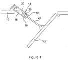
- FIG. 1 there is illustrated, diagrammatically, a part of an engine housing 10 including a door 12 movable between a closed, in use position and an open position.
- the door 12 is shown in its open position in Figure 1 .
- the door 12 is arranged to be driven between these positions by an actuator 14 in the form of a hydraulic piston or ram.
- the actuator 14 comprises a housing 16 defining a cylinder 18 within which a piston 20 is slidable, an output shaft 22 being connected to the piston 20.
- the housing 16 is mounted to the engine housing 10 whilst the door 12 is connected to an end of the output shaft 22.
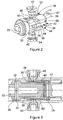
- a sleeve 26 encircles part of the output shaft 22.
- the sleeve 26 is secured to the output shaft 22 in such a manner that axial movement of the sleeve 26 relative to the shaft 22 is prevented or restricted, whilst the sleeve 26 is capable of rotation relative to the output shaft 22.
- the sleeve 26 Whilst such mounting of the sleeve 26 to the shaft 22 may be achieved in a number of ways, in the arrangement illustrated the sleeve 26 is held captive to the shaft 22 by virtue of a step 28 provided on the shaft 22 restricting or preventing movement of the sleeve 26 in one axial direction, and a collar 30 secured to the shaft 22 by pins 32 which extend through openings formed in the shaft 22 which prevents or restricts movement of the sleeve 26 in the opposite axial direction.
- the sleeve 26 is shaped to define a lock formation 34 including entry and exit passages 36 and lock pockets 38.
- the actuator housing 16 carries a pair of radially extending pins 40, the pins 40 being arranged and positioned such that as the actuator approaches its fully extended position, the sleeve 26 approaches and is positioned adjacent the pins 40, and the inner ends of the pins 40 enter respective ones of the passages 36.
- the passages 36 are formed with enlarged mouths 42 to assist in entry of the end parts of the pins 40 into the passages 36, and so reduce the risk of the pins 40 butting against the end of the sleeve 26.
- the actuator further comprises resilient detent means 44 in the form of a series of resilient fingers 46 extending within and along respective ones of the passages 36.
- the fingers 46 are interconnected by a collar 47 which is engaged between the sleeve 26 and the step 28, thereby securing the fingers 46 in position.
- Each finger 46 is shaped, at its free end, to be of increased radial dimension, a ramp 48 being provided on the outer surface thereof. In use, as the actuator approaches its fully extended position, the pins 40 bear against the ramps 48, causing the end parts of the fingers 46 to deflect radially inwards until the fully extended actuator position is reached.
- each finger 46 includes a sloped end surface 50, the slope being orientated such that the cooperation between the pins 40 and sloped surfaces 50 that occurs upon retracting movement of the actuator causes rotation of the sleeve 26 relative to the pins 40 and the housing 16.
- the pins 40 prevent further retracting movement of the actuator, thus the actuator is locked in an extended position just short of its fully extended position, holding the door 12 in its open position.
- the actuator 14 From the locked position, in order to retract the actuator and close the door 12, the actuator 14 must first be returned to its fully extended position. Such movement brings the pins 40 into contact with ramped release surfaces 54, driving the sleeve 26 for rotation with the result that, upon subsequent retraction of the actuator, the pins 40 move into engagement with ramped surfaces 56 causing further rotation of the sleeve 26 until the pins 40 are able to enter the adjacent passages 36. It will be appreciated that, during such movement, the pins 40 ride onto parts of the fingers 46 spaced from the increased diameter end parts thereof, and so no deflection of the fingers 46 is required during such movement.
- each passage 36 is able to serve as both an entry passage along which the pins 40 pass during extending movement and as an exit passage along which the pins 40 move during retraction.
- the passage which are, initially, angularly aligned with the pins 40 as the actuator extends serve as entry passages, and the adjacent passages serve, subsequently, as exit passages.
- the passages which had last served as the exit passages will be aligned with the pins and so will serve as entry passages, no rotation of the sleeve 26 having occurred.
- a spring biased retainer 60 may be provided to interact with formations provided internally of the sleeve 26 to resist undesired angular movement.
- the actuator of the present invention is of simple and convenient form. It is envisaged that existing actuators may be modified to incorporate the invention by removal of certain ramped surfaces thereof and by the addition of the detent means. The modifications necessary to incorporate the invention are sufficiently small that it is thought that the invention may be retrofitted to existing actuators in a convenient manner.
- the detent means could be modified to include pins which are resiliently biased and arranged to ride over fixed ramps, rather than providing fixed pins which cause deflection of ramped fingers, to provide the detent means.
- the description hereinbefore relates primarily to an hydraulically operated actuator, it will be appreciated that the invention is not restricted in this regard and could be applied to, for example, electric motor driven actuators or the like. Other arrangements are also possible.
Landscapes
- Engineering & Computer Science (AREA)
- Physics & Mathematics (AREA)
- Fluid Mechanics (AREA)
- Mechanical Engineering (AREA)
- General Engineering & Computer Science (AREA)
- Lock And Its Accessories (AREA)
- Preventing Unauthorised Actuation Of Valves (AREA)
- Actuator (AREA)
Claims (12)
- Aktuator, umfassend eine Akutatorausgangswelle (22) und eine drehbare Sperrstruktur (26), dadurch gekennzeichnet, dass die drehbare Sperrstruktur (26) der Ausgangswelle (22) zugeordnet ist, um bezogen darauf axial fixiert zu sein, wobei die Sperrstruktur (26) einen Eintrittsdurchlass (36), eine Sperraussparung (38) und einen Austrittsdurchlass (36) definiert, wobei ein Stift (40) zur Bewegung bezogen auf die Sperrstruktur (26) angeordnet ist, sodass ein Teil des Stifts (40) in den Eintrittsdurchlass (36) aufgenommen und entlang diesem geführt wird, wenn sich der Aktuator einer vollständig ausgefahrenen Position nähert, und ein elastisches Rastmittel (44) derart betätigt werden kann, dass das elastische Rastmittel (44) eine Rückbewegung des Stifts (40) entlang des Eintrittsdurchlasses (36) verhindert, sobald sich der Stift (40) über eine vorbestimmte Position in dem Eintrittsdurchlass (36) hinaus bewegt hat.
- Aktuator nach Anspruch 1, wobei das elastische Rastmittel (44) einen elastischen Finger (46) umfasst, der ablenkt, wenn der Stift (40) über den Finger (46) geführt wird, wobei es eine Bewegung des Stifts (40) an dem Finger (46) vorbei dem Finger (46) ermöglicht, in eine Ruheposition zurückzukehren, in der er eine Rückbewegung des Stifts entlang des Eintrittsdurchlasses (36) verhindert.
- Aktuator nach Anspruch 2, wobei der Finger (46) eine schräge Endfläche (50) beinhaltet, die mit dem Stift (40) zusammenwirken kann, um zu einer Drehung der Sperrstruktur (26) zu führen, um den Stift (40) in einer Rückbewegung in Richtung der Sperraussparung (38) zu lenken.
- Aktuator nach einem der vorhergehenden Ansprüche, wobei die Sperrstruktur (26) eine geneigte Trennfläche (54) beinhaltet, die derart angeordnet ist, dass durch eine Bewegung des Aktuators aus der gesperrten Position in die vollständig ausgefahrene Position der Stift (40) mit der geneigten Trennfläche (54) in Eingriff gebracht wird, was zu einer Drehung der Sperrstruktur (26) in eine Position führt, in welcher der Stift (40) bei nachfolgendem Zurückziehen des Aktuators in den Austrittsdurchlass (36) eintritt und durch diesen geführt wird.
- Aktuator nach einem der vorhergehenden Ansprüche, wobei die Sperrstruktur (26) einen Mantel umfasst, der einen Teil der Ausgangswelle (22) umgibt, wobei der Mantel bezogen auf die Welle (22) drehbar, jedoch axial fixiert bezogen auf die Welle (22) ist.
- Aktuator nach einem der Ansprüche 1 bis 4, wobei die Sperrstruktur starr an der Ausgangswelle befestigt oder damit einstückig ist, wobei die Ausgangswelle drehbar ist.
- Aktuator nach einem der vorhergehenden Ansprüche, wobei der Aktuator zumindest zwei Stifte (40) beinhaltet.
- Aktuator nach einem der vorhergehenden Ansprüche, wobei jeder Austrittsdurchlass (36) auf eine solche Weise ausgebildet ist, dass er abhängig von der Winkelposition der Sperrstruktur (26), wenn der Aktuator aus der zurückgezogenen Position bewegt wird und sich der vollständig ausgefahrenen Position nähert, außerdem als ein Eintrittsdurchlass (36) dienen kann.
- Aktuator nach einem der vorhergehenden Ansprüche, wobei die Finger (46) auf einem Bund (47) bereitgestellt sind, wobei sich jeder Finger (46) entlang eines entsprechenden einen der Eingangsdurchlässe (36) erstreckt.
- Aktuator nach Anspruch 9, wobei der freie Endabschnitt von jedem Finger (46) von erhöhter radialer Dicke ist, wobei der Endabschnitt durch das Zusammenwirken davon mit dem Stift (40) abgelenkt wird, wenn der Stift (40) über den Endabschnitt geführt wird.
- Aktuator nach einem der vorhergehenden Ansprüche, ferner umfassend ein Aktuatorgehäuse, auf dem der Stift (40) angebracht ist.
- Aktuator nach einem der vorhergehenden Ansprüche, wobei der Aktuator ein hydraulisch angetriebener Aktuator ist, wobei die Ausgangswelle (22) mit einem Kolben verbunden ist, der mit einem Zylinder des Aktuators verschoben werden kann.
Applications Claiming Priority (1)
| Application Number | Priority Date | Filing Date | Title |
|---|---|---|---|
| GB201109487A GB201109487D0 (en) | 2011-06-07 | 2011-06-07 | Actuator with locking arrangement |
Publications (3)
| Publication Number | Publication Date |
|---|---|
| EP2532821A2 EP2532821A2 (de) | 2012-12-12 |
| EP2532821A3 EP2532821A3 (de) | 2015-09-23 |
| EP2532821B1 true EP2532821B1 (de) | 2017-10-04 |
Family
ID=44343497
Family Applications (1)
| Application Number | Title | Priority Date | Filing Date |
|---|---|---|---|
| EP12250120.8A Active EP2532821B1 (de) | 2011-06-07 | 2012-06-01 | Aktuator mit Sperranordnung |
Country Status (3)
| Country | Link |
|---|---|
| US (1) | US9140048B2 (de) |
| EP (1) | EP2532821B1 (de) |
| GB (1) | GB201109487D0 (de) |
Families Citing this family (6)
| Publication number | Priority date | Publication date | Assignee | Title |
|---|---|---|---|---|
| EP3059369B1 (de) | 2015-02-19 | 2021-09-01 | Goodrich Actuation Systems Ltd. | Stellantrieb |
| EP3244071B1 (de) | 2016-05-06 | 2019-04-17 | Goodrich Aerospace Services Pvt Ltd | Betätigungsmechanismus |
| CN107558853A (zh) * | 2017-09-04 | 2018-01-09 | 江西洪都航空工业集团有限责任公司 | 一种座舱盖开启机构 |
| GB2566556B (en) | 2017-09-19 | 2020-01-15 | Edo Mbm Tech Limited | Actuator rotational alignment device |
| FR3081237B1 (fr) * | 2018-05-18 | 2020-12-18 | Safran Landing Systems | Actionneur telescopique a verrouillage automatique |
| CN115522815B (zh) * | 2022-10-25 | 2024-08-13 | 中国商用飞机有限责任公司 | 货舱门作动器应力释放方法和货舱门操作装置 |
Family Cites Families (2)
| Publication number | Priority date | Publication date | Assignee | Title |
|---|---|---|---|---|
| US3799036A (en) * | 1972-07-17 | 1974-03-26 | R Slaughter | Self-locking fluid operated cylinder |
| GB0813906D0 (en) * | 2008-07-30 | 2008-09-03 | Goodrich Actuation Systems Ltd | Actuator |
-
2011
- 2011-06-07 GB GB201109487A patent/GB201109487D0/en not_active Ceased
-
2012
- 2012-05-31 US US13/484,555 patent/US9140048B2/en active Active
- 2012-06-01 EP EP12250120.8A patent/EP2532821B1/de active Active
Non-Patent Citations (1)
| Title |
|---|
| None * |
Also Published As
| Publication number | Publication date |
|---|---|
| US20120312154A1 (en) | 2012-12-13 |
| EP2532821A2 (de) | 2012-12-12 |
| US9140048B2 (en) | 2015-09-22 |
| EP2532821A3 (de) | 2015-09-23 |
| GB201109487D0 (en) | 2011-07-20 |
Similar Documents
| Publication | Publication Date | Title |
|---|---|---|
| US9140048B2 (en) | Actuator with locking arrangement | |
| EP2604514B1 (de) | Linearer Aktuator mit automatischer Sperre | |
| CA2865114C (en) | Drive assembly with selective disconnect | |
| EP2149496B1 (de) | Stellantrieb | |
| EP3406888B1 (de) | Aktuator | |
| EP3757054B1 (de) | Elektrische betätigungsanordnung für verbolzten kranausleger | |
| RU2635748C2 (ru) | Приводное устройство для перемещения подвижного капота реверса тяги | |
| EP3931434B1 (de) | Verfahrbares fingerschloss für einen aktuator | |
| EP3284677B1 (de) | Ver- und entriegelungsmechanismus | |
| EP3084221B1 (de) | Kfz-vakuumpumpe mit schaltbarer kupplung | |
| EP3473550B1 (de) | Elektrische teleskopstrebenkonstruktion | |
| EP3059369B1 (de) | Stellantrieb | |
| US10012246B2 (en) | Failsafe deployment feature for actuator | |
| US10344710B2 (en) | Engine with a thrust reverser lockout mechanism | |
| EP3244071B1 (de) | Betätigungsmechanismus | |
| EP3529511B1 (de) | Kupplungsanordnung für ein hybridfahrzeug | |
| EP3882454B1 (de) | Verriegelnder linearer aktuator | |
| US20070084690A1 (en) | Low inertia ball brake/clutch | |
| CN120968352A (zh) | 一种带解锁保持功能的自动上锁结构 | |
| EP2169151A1 (de) | Sicherheitsschloss | |
| JP2017536509A (ja) | 向上した配置システムを備えた宇宙船ノズル | |
| NL2013682B1 (en) | Assemblies of a cylinder and a coupling part and/or of a line and a complementary coupling part, a coupling part, a complementary coupling part and a coupling defined by a coupling part and a complementary coupling part. | |
| WO2014174262A1 (en) | Failsafe mechanism | |
| DE102008029524A1 (de) | Schaltbarer Klemmkörper-Freilauf |
Legal Events
| Date | Code | Title | Description |
|---|---|---|---|
| PUAI | Public reference made under article 153(3) epc to a published international application that has entered the european phase |
Free format text: ORIGINAL CODE: 0009012 |
|
| AK | Designated contracting states |
Kind code of ref document: A2 Designated state(s): AL AT BE BG CH CY CZ DE DK EE ES FI FR GB GR HR HU IE IS IT LI LT LU LV MC MK MT NL NO PL PT RO RS SE SI SK SM TR |
|
| AX | Request for extension of the european patent |
Extension state: BA ME |
|
| PUAL | Search report despatched |
Free format text: ORIGINAL CODE: 0009013 |
|
| AK | Designated contracting states |
Kind code of ref document: A3 Designated state(s): AL AT BE BG CH CY CZ DE DK EE ES FI FR GB GR HR HU IE IS IT LI LT LU LV MC MK MT NL NO PL PT RO RS SE SI SK SM TR |
|
| AX | Request for extension of the european patent |
Extension state: BA ME |
|
| RIC1 | Information provided on ipc code assigned before grant |
Ipc: F15B 15/26 20060101ALI20150820BHEP Ipc: E05F 15/12 00000000ALI20150820BHEP Ipc: E05F 15/04 00000000AFI20150820BHEP |
|
| 17P | Request for examination filed |
Effective date: 20160323 |
|
| RBV | Designated contracting states (corrected) |
Designated state(s): AL AT BE BG CH CY CZ DE DK EE ES FI FR GB GR HR HU IE IS IT LI LT LU LV MC MK MT NL NO PL PT RO RS SE SI SK SM TR |
|
| REG | Reference to a national code |
Ref country code: DE Ref legal event code: R079 Ref document number: 602012038075 Country of ref document: DE Free format text: PREVIOUS MAIN CLASS: E05F0015040000 Ipc: E05F0015530000 |
|
| GRAP | Despatch of communication of intention to grant a patent |
Free format text: ORIGINAL CODE: EPIDOSNIGR1 |
|
| STAA | Information on the status of an ep patent application or granted ep patent |
Free format text: STATUS: GRANT OF PATENT IS INTENDED |
|
| RIC1 | Information provided on ipc code assigned before grant |
Ipc: E05F 15/53 20150101AFI20170316BHEP Ipc: E05F 15/611 20150101ALI20170316BHEP |
|
| INTG | Intention to grant announced |
Effective date: 20170419 |
|
| GRAA | (expected) grant |
Free format text: ORIGINAL CODE: 0009210 |
|
| GRAS | Grant fee paid |
Free format text: ORIGINAL CODE: EPIDOSNIGR3 |
|
| STAA | Information on the status of an ep patent application or granted ep patent |
Free format text: STATUS: THE PATENT HAS BEEN GRANTED |
|
| AK | Designated contracting states |
Kind code of ref document: B1 Designated state(s): AL AT BE BG CH CY CZ DE DK EE ES FI FR GB GR HR HU IE IS IT LI LT LU LV MC MK MT NL NO PL PT RO RS SE SI SK SM TR |
|
| REG | Reference to a national code |
Ref country code: GB Ref legal event code: FG4D |
|
| REG | Reference to a national code |
Ref country code: CH Ref legal event code: EP |
|
| REG | Reference to a national code |
Ref country code: AT Ref legal event code: REF Ref document number: 934221 Country of ref document: AT Kind code of ref document: T Effective date: 20171015 |
|
| REG | Reference to a national code |
Ref country code: IE Ref legal event code: FG4D |
|
| REG | Reference to a national code |
Ref country code: DE Ref legal event code: R096 Ref document number: 602012038075 Country of ref document: DE |
|
| REG | Reference to a national code |
Ref country code: NL Ref legal event code: MP Effective date: 20171004 |
|
| REG | Reference to a national code |
Ref country code: LT Ref legal event code: MG4D |
|
| REG | Reference to a national code |
Ref country code: AT Ref legal event code: MK05 Ref document number: 934221 Country of ref document: AT Kind code of ref document: T Effective date: 20171004 |
|
| PG25 | Lapsed in a contracting state [announced via postgrant information from national office to epo] |
Ref country code: NL Free format text: LAPSE BECAUSE OF FAILURE TO SUBMIT A TRANSLATION OF THE DESCRIPTION OR TO PAY THE FEE WITHIN THE PRESCRIBED TIME-LIMIT Effective date: 20171004 |
|
| PG25 | Lapsed in a contracting state [announced via postgrant information from national office to epo] |
Ref country code: NO Free format text: LAPSE BECAUSE OF FAILURE TO SUBMIT A TRANSLATION OF THE DESCRIPTION OR TO PAY THE FEE WITHIN THE PRESCRIBED TIME-LIMIT Effective date: 20180104 Ref country code: LT Free format text: LAPSE BECAUSE OF FAILURE TO SUBMIT A TRANSLATION OF THE DESCRIPTION OR TO PAY THE FEE WITHIN THE PRESCRIBED TIME-LIMIT Effective date: 20171004 Ref country code: SE Free format text: LAPSE BECAUSE OF FAILURE TO SUBMIT A TRANSLATION OF THE DESCRIPTION OR TO PAY THE FEE WITHIN THE PRESCRIBED TIME-LIMIT Effective date: 20171004 Ref country code: ES Free format text: LAPSE BECAUSE OF FAILURE TO SUBMIT A TRANSLATION OF THE DESCRIPTION OR TO PAY THE FEE WITHIN THE PRESCRIBED TIME-LIMIT Effective date: 20171004 Ref country code: FI Free format text: LAPSE BECAUSE OF FAILURE TO SUBMIT A TRANSLATION OF THE DESCRIPTION OR TO PAY THE FEE WITHIN THE PRESCRIBED TIME-LIMIT Effective date: 20171004 |
|
| PG25 | Lapsed in a contracting state [announced via postgrant information from national office to epo] |
Ref country code: AT Free format text: LAPSE BECAUSE OF FAILURE TO SUBMIT A TRANSLATION OF THE DESCRIPTION OR TO PAY THE FEE WITHIN THE PRESCRIBED TIME-LIMIT Effective date: 20171004 Ref country code: BG Free format text: LAPSE BECAUSE OF FAILURE TO SUBMIT A TRANSLATION OF THE DESCRIPTION OR TO PAY THE FEE WITHIN THE PRESCRIBED TIME-LIMIT Effective date: 20180104 Ref country code: LV Free format text: LAPSE BECAUSE OF FAILURE TO SUBMIT A TRANSLATION OF THE DESCRIPTION OR TO PAY THE FEE WITHIN THE PRESCRIBED TIME-LIMIT Effective date: 20171004 Ref country code: GR Free format text: LAPSE BECAUSE OF FAILURE TO SUBMIT A TRANSLATION OF THE DESCRIPTION OR TO PAY THE FEE WITHIN THE PRESCRIBED TIME-LIMIT Effective date: 20180105 Ref country code: RS Free format text: LAPSE BECAUSE OF FAILURE TO SUBMIT A TRANSLATION OF THE DESCRIPTION OR TO PAY THE FEE WITHIN THE PRESCRIBED TIME-LIMIT Effective date: 20171004 Ref country code: IS Free format text: LAPSE BECAUSE OF FAILURE TO SUBMIT A TRANSLATION OF THE DESCRIPTION OR TO PAY THE FEE WITHIN THE PRESCRIBED TIME-LIMIT Effective date: 20180204 Ref country code: HR Free format text: LAPSE BECAUSE OF FAILURE TO SUBMIT A TRANSLATION OF THE DESCRIPTION OR TO PAY THE FEE WITHIN THE PRESCRIBED TIME-LIMIT Effective date: 20171004 |
|
| REG | Reference to a national code |
Ref country code: FR Ref legal event code: PLFP Year of fee payment: 7 |
|
| REG | Reference to a national code |
Ref country code: DE Ref legal event code: R097 Ref document number: 602012038075 Country of ref document: DE |
|
| PG25 | Lapsed in a contracting state [announced via postgrant information from national office to epo] |
Ref country code: CZ Free format text: LAPSE BECAUSE OF FAILURE TO SUBMIT A TRANSLATION OF THE DESCRIPTION OR TO PAY THE FEE WITHIN THE PRESCRIBED TIME-LIMIT Effective date: 20171004 Ref country code: SK Free format text: LAPSE BECAUSE OF FAILURE TO SUBMIT A TRANSLATION OF THE DESCRIPTION OR TO PAY THE FEE WITHIN THE PRESCRIBED TIME-LIMIT Effective date: 20171004 Ref country code: DK Free format text: LAPSE BECAUSE OF FAILURE TO SUBMIT A TRANSLATION OF THE DESCRIPTION OR TO PAY THE FEE WITHIN THE PRESCRIBED TIME-LIMIT Effective date: 20171004 Ref country code: EE Free format text: LAPSE BECAUSE OF FAILURE TO SUBMIT A TRANSLATION OF THE DESCRIPTION OR TO PAY THE FEE WITHIN THE PRESCRIBED TIME-LIMIT Effective date: 20171004 |
|
| PLBE | No opposition filed within time limit |
Free format text: ORIGINAL CODE: 0009261 |
|
| STAA | Information on the status of an ep patent application or granted ep patent |
Free format text: STATUS: NO OPPOSITION FILED WITHIN TIME LIMIT |
|
| PG25 | Lapsed in a contracting state [announced via postgrant information from national office to epo] |
Ref country code: PL Free format text: LAPSE BECAUSE OF FAILURE TO SUBMIT A TRANSLATION OF THE DESCRIPTION OR TO PAY THE FEE WITHIN THE PRESCRIBED TIME-LIMIT Effective date: 20171004 Ref country code: RO Free format text: LAPSE BECAUSE OF FAILURE TO SUBMIT A TRANSLATION OF THE DESCRIPTION OR TO PAY THE FEE WITHIN THE PRESCRIBED TIME-LIMIT Effective date: 20171004 Ref country code: SM Free format text: LAPSE BECAUSE OF FAILURE TO SUBMIT A TRANSLATION OF THE DESCRIPTION OR TO PAY THE FEE WITHIN THE PRESCRIBED TIME-LIMIT Effective date: 20171004 |
|
| 26N | No opposition filed |
Effective date: 20180705 |
|
| PG25 | Lapsed in a contracting state [announced via postgrant information from national office to epo] |
Ref country code: SI Free format text: LAPSE BECAUSE OF FAILURE TO SUBMIT A TRANSLATION OF THE DESCRIPTION OR TO PAY THE FEE WITHIN THE PRESCRIBED TIME-LIMIT Effective date: 20171004 |
|
| REG | Reference to a national code |
Ref country code: CH Ref legal event code: PL |
|
| REG | Reference to a national code |
Ref country code: BE Ref legal event code: MM Effective date: 20180630 |
|
| REG | Reference to a national code |
Ref country code: IE Ref legal event code: MM4A |
|
| PG25 | Lapsed in a contracting state [announced via postgrant information from national office to epo] |
Ref country code: LU Free format text: LAPSE BECAUSE OF NON-PAYMENT OF DUE FEES Effective date: 20180601 Ref country code: MC Free format text: LAPSE BECAUSE OF FAILURE TO SUBMIT A TRANSLATION OF THE DESCRIPTION OR TO PAY THE FEE WITHIN THE PRESCRIBED TIME-LIMIT Effective date: 20171004 |
|
| PG25 | Lapsed in a contracting state [announced via postgrant information from national office to epo] |
Ref country code: CH Free format text: LAPSE BECAUSE OF NON-PAYMENT OF DUE FEES Effective date: 20180630 Ref country code: LI Free format text: LAPSE BECAUSE OF NON-PAYMENT OF DUE FEES Effective date: 20180630 Ref country code: IE Free format text: LAPSE BECAUSE OF NON-PAYMENT OF DUE FEES Effective date: 20180601 |
|
| PG25 | Lapsed in a contracting state [announced via postgrant information from national office to epo] |
Ref country code: BE Free format text: LAPSE BECAUSE OF NON-PAYMENT OF DUE FEES Effective date: 20180630 |
|
| PG25 | Lapsed in a contracting state [announced via postgrant information from national office to epo] |
Ref country code: MT Free format text: LAPSE BECAUSE OF NON-PAYMENT OF DUE FEES Effective date: 20180601 |
|
| PG25 | Lapsed in a contracting state [announced via postgrant information from national office to epo] |
Ref country code: TR Free format text: LAPSE BECAUSE OF FAILURE TO SUBMIT A TRANSLATION OF THE DESCRIPTION OR TO PAY THE FEE WITHIN THE PRESCRIBED TIME-LIMIT Effective date: 20171004 |
|
| PG25 | Lapsed in a contracting state [announced via postgrant information from national office to epo] |
Ref country code: PT Free format text: LAPSE BECAUSE OF FAILURE TO SUBMIT A TRANSLATION OF THE DESCRIPTION OR TO PAY THE FEE WITHIN THE PRESCRIBED TIME-LIMIT Effective date: 20171004 Ref country code: HU Free format text: LAPSE BECAUSE OF FAILURE TO SUBMIT A TRANSLATION OF THE DESCRIPTION OR TO PAY THE FEE WITHIN THE PRESCRIBED TIME-LIMIT; INVALID AB INITIO Effective date: 20120601 |
|
| PG25 | Lapsed in a contracting state [announced via postgrant information from national office to epo] |
Ref country code: CY Free format text: LAPSE BECAUSE OF FAILURE TO SUBMIT A TRANSLATION OF THE DESCRIPTION OR TO PAY THE FEE WITHIN THE PRESCRIBED TIME-LIMIT Effective date: 20171004 Ref country code: MK Free format text: LAPSE BECAUSE OF NON-PAYMENT OF DUE FEES Effective date: 20171004 |
|
| PG25 | Lapsed in a contracting state [announced via postgrant information from national office to epo] |
Ref country code: AL Free format text: LAPSE BECAUSE OF FAILURE TO SUBMIT A TRANSLATION OF THE DESCRIPTION OR TO PAY THE FEE WITHIN THE PRESCRIBED TIME-LIMIT Effective date: 20171004 |
|
| P01 | Opt-out of the competence of the unified patent court (upc) registered |
Effective date: 20230706 |
|
| PGFP | Annual fee paid to national office [announced via postgrant information from national office to epo] |
Ref country code: DE Payment date: 20250520 Year of fee payment: 14 |
|
| PGFP | Annual fee paid to national office [announced via postgrant information from national office to epo] |
Ref country code: GB Payment date: 20250520 Year of fee payment: 14 |
|
| PGFP | Annual fee paid to national office [announced via postgrant information from national office to epo] |
Ref country code: IT Payment date: 20250520 Year of fee payment: 14 |
|
| PGFP | Annual fee paid to national office [announced via postgrant information from national office to epo] |
Ref country code: FR Payment date: 20250520 Year of fee payment: 14 |