EP3244071B1 - Betätigungsmechanismus - Google Patents
Betätigungsmechanismus Download PDFInfo
- Publication number
- EP3244071B1 EP3244071B1 EP16178233.9A EP16178233A EP3244071B1 EP 3244071 B1 EP3244071 B1 EP 3244071B1 EP 16178233 A EP16178233 A EP 16178233A EP 3244071 B1 EP3244071 B1 EP 3244071B1
- Authority
- EP
- European Patent Office
- Prior art keywords
- actuator
- pin
- detent
- lock
- collar
- Prior art date
- Legal status (The legal status is an assumption and is not a legal conclusion. Google has not performed a legal analysis and makes no representation as to the accuracy of the status listed.)
- Active
Links
Images







Classifications
-
- F—MECHANICAL ENGINEERING; LIGHTING; HEATING; WEAPONS; BLASTING
- F15—FLUID-PRESSURE ACTUATORS; HYDRAULICS OR PNEUMATICS IN GENERAL
- F15B—SYSTEMS ACTING BY MEANS OF FLUIDS IN GENERAL; FLUID-PRESSURE ACTUATORS, e.g. SERVOMOTORS; DETAILS OF FLUID-PRESSURE SYSTEMS, NOT OTHERWISE PROVIDED FOR
- F15B15/00—Fluid-actuated devices for displacing a member from one position to another; Gearing associated therewith
- F15B15/20—Other details, e.g. assembly with regulating devices
- F15B15/26—Locking mechanisms
- F15B15/261—Locking mechanisms using positive interengagement, e.g. balls and grooves, for locking in the end positions
-
- B—PERFORMING OPERATIONS; TRANSPORTING
- B64—AIRCRAFT; AVIATION; COSMONAUTICS
- B64D—EQUIPMENT FOR FITTING IN OR TO AIRCRAFT; FLIGHT SUITS; PARACHUTES; ARRANGEMENT OR MOUNTING OF POWER PLANTS OR PROPULSION TRANSMISSIONS IN AIRCRAFT
- B64D29/00—Power-plant nacelles, fairings or cowlings
- B64D29/06—Attaching of nacelles, fairings or cowlings
Definitions
- the present disclosure relates to an actuator mechanism moveable between a locked and an unlocked position.
- the mechanism is particularly, but not exclusively, for use in aircraft engines, and finds particular application in opening and closing aircraft engine cowls.
- Aircraft engine cowls such as those covering the C-duct and fans need to be opened occasionally to allow access to the engine for e.g. repair and maintenance, and then closed again.
- Actuators are provided to open and close the cowls. Preferably no pressure or driving force should be required to keep the actuator in the open position, despite the weight of the cowl door.
- the actuators generally comprise an extendible rod or arm that is attached to open the cowl as it extends and close the cowl as it retracts under the weight of the cowl door.
- a typical hydraulic actuator comprises a piston rod, a cylinder and a rotatable lock mechanism to facilitate mechanical operation of the cowl door or flap. Pressure is applied to fully extend the actuator; when fully extended, pressure is removed allowing the actuator to retract by a small amount which causes the actuator to lock, as the lock mechanism rotates and engages the actuator. To close, or stow, the cowl door, the actuator is then extended by application of pressure out of the locked position to its fully extended position from which, as pressure is removed, the actuator is able to return to a retracted, stowed, position.
- a rotatable lock mechanism in cooperation with a locking pin, provides the paths for the actuator to take up its locked position or return to its stowed position, as will be described further below.
- EP 2532821 describes an improved actuator mechanism that avoids the actuator stopping in such an intermediate position.
- EP 2532821 provides a resilient detent in the paths for a locking pin provided by the lock mechanism such that once the locking pin has moved beyond a predetermined position in the extending direction the resilient detent prevents return movement of the pin along the entry path.
- a further problem has been identified with the known actuator mechanism when the actuator is used to return the cowl to the stowed state.
- the actuator is extended (out of the locked state) and then, due to the paths defined by the lock mechanism, returns to the retracted state, via an exit path.
- the pin can again become stuck in position at an intermediate point, rather than automatically feed into and follow the exit path under the weight of the cowl. This intermediate position can be falsely interpreted as a locked state. If the actuator is jolted or slightly disturbed, the locking pin can slip from the intermediate point, back into the locked position, which can damage the door as well as damage other parts or cause injury.
- a spring biased detent ball retainer ensures that before the actuator locks onto such an intermediate point, the detent ball which is timed to run over a cam-like profile, rotates the lock collar so that the locking pin either moves into the locked state or the unlocked state.
- Torque generated by the spring biased detent ball shall always be greater than the varying resistive torque.
- the torque generated is highly sensitive to the cam-like profile that the detent ball traces.
- the resistive torque depends upon factors such as thickness of the thin fluid film between the piston and lock collar (clearance), viscous drag on surfaces of rotating components, viscosity of working fluid which is, in turn, a function of ambient temperature.
- the present disclosure therefore aims to provide an actuator locking mechanism that can prevent the actuator becoming stuck in an intermediate position when intended to be moved from the locked position to the stowed position, without reliance on a spring biased detent ball.
- the present disclosure provides an actuator system comprising a rotatable lock mechanism defining a path for an actuator pin as the actuator is expanded and retracted, wherein the lock mechanism defines an entry passage through which the pin enters as the actuator extends, a guide surface along which the pin travels from the entry passage as the actuator retracts, a locking recess into which the pin is guided by the guide surface, and an exit passage into which the pin is guided as it is caused to leave the locking recess by extension of the actuator and subsequent retraction; whereby a detent surface is provided to prevent the pin returning back into the locking recess when the actuator is extended to cause the pin to leave the locking recess, wherein the lock mechanism comprises a collar defining the path and a tine gate fitted within the collar and comprising a detent finger defining the detent.
- the guide surface and/or the detent surface provide a slope.
- a detent surface may also be provided in the entry passage.
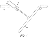
- Fig. 1 shows an actuator according to an embodiment of the invention, in use.
- Fig. 1 shows part of an engine housing 10 including a door 12 moveable between a closed, in use position, and an open position.
- the door 12 is shown in its open position.
- An actuator 14 is arranged to drive the door between the two positions.
- the actuator is in the form of a hydraulic piston or ram comprising a housing cylinder within which a piston is slidable.
- the cylinder is mounted to the engine housing 10, by means of an eye end (shown in Fig. 2 ), while the door is connected to an end of the piston rod, again via an eye end.
- By controlling the pressure of fluid applied to a chamber within the actuator extension and retraction of the actuator can be controlled so as to drive the door between its closed and opened positions.
- Other types of actuators may be used, including electrically or mechanically driven actuators.
- the actuator comprises an eye 50a, 50b at each end for attachment, respectively, to the engine and to the door to be opened and closed.
- a cylinder 51 runs between the ends within which an piston rod is axially slidably mounted.
- a port 53 is provided through the cylinder close to one end, through which fluid can be provided to hydraulically move the piston rod within/along the cylinder.
- a rotating lock mechanism 54 is provided at an end of the piston (the end closest to the port when the piston is retracted within the cylinder). The lock mechanism is fixed to move axially with the piston rod and is rotatable within the cylinder.
- One or more locking pins 10 are mounted on and extend through the cylinder wall at a location between the fluid port and the opposite end of the cylinder. As pressure is applied to the piston rod via the fluid port, the rod, together with the lock mechanism, moves axially away from the port, extending the actuator rod and moving the lock mechanism towards the pin(s).
- the lock mechanism defines a path for the locking pin(s) including an entry passage, a locking recess, and an exit passage.
- the lock mechanism comprises a lock collar comprising a collar having the path defined in its outer surface and, preferably, grooves in e.g. a helical formation on its inner surface.
- a spring biased detent ball arrangement 8 is biased across the inner bore of the collar such that a spring biases balls to run in and out of the grooves in the inner surface.
- the lock mechanism also comprises guide surfaces to direct the pins along appropriate paths, and detent means, as described above. These are provided on one or more gates or rings, known as a tine gate, that cooperate with and are nested within the collar.
- the nested arrangement of the tine gate within the lock collar reinforces or strengthens the detent finger part of the tine gate to protect it against breakage. The pins ride over the detent finger several times causing it to deflect and this repeated deflection could cause the detent finger to break. The nested arrangement prevents or minimises this.
- the preferred lock mechanism is mounted about a piston rod 1.
- a tine gate 2 comprising detent fingers 3 defining detent surfaces 4 is held or nested between a sleeve 5 and a lock collar 6.
- the sleeve 5, tine gate 2 and lock collar 6 can be held together by e.g. dowel pins 7.
- the internal diameter of the sleeve has an indexed surface which supports spring biased detent balls 8.
- the spring biased detent balls orient the lock mechanism with respect to the locking pins 10.
- the tine gate 2 provides a resilient detent at the exit of the passage leading to the locking recess.
- the detent deflects down as the pin rides over it as the actuator extends to release the lock and, due to its resilience, springs up to form a detent once the pin has passed over it. Thus, even if the actuator is not fully extended, the pin is prevented from returning to the locking recess.
- the detent is preferably also formed with a sloping surface or ramp such that as the pin passes over the detent, and pressure is removed, the pin rides along this ramp to cause rotation of the lock collar and guide the pin into the exit passageway from which it exits the lock collar to retract the actuator.
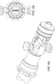
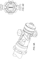
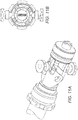
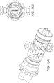
- the lock mechanism engages the pin(s) in the cylinder, such that a pin enters an entry passage of the lock collar ( Figs. 5A, 5B ).
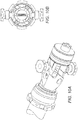
- the pin moves into the entry passage ( Figs. 6A, 6B ) riding over a resilient detent finger and pressing it down. After a certain degree of extension, the pin has reached the end of the entry passage and passes over the detent finger which springs back to its raised position so that the pin cannot return along the entry passage ( Figs. 7A, 7B ).
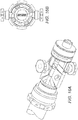
- the actuator is extended further, to its fully extended position. Pressure is then removed from the piston rod ( Figs. 8A, 8B ).
- Resilient detent means are provided in the passages. As the pin runs over these, it presses them down. Once the pin has passed over the detent means, in some embodiments, the detent means springs pack up preventing return of the pin and also preferably providing a sloped guide surface.
- the spring biased detent ball also helps to drive the actuator into an end state (locked or stowed) rather than hanging at an intermediate point.
- the reliability and extent of support from the detent ball is, however, very limited, as mentioned above.
- the present disclosure provides an improved mechanism for preventing the pin falling back into the locked position.
- the locking pins come into engagement with the lock collar.
- the surface of the lock collar with which the pins first come into contact is sloped or helical, for reasons described more below, as opposed to having long flat lands.
- the pins enter the entry passage as the actuator is extended. As the actuator continues to extend, the pin passes over the resilient detent at the end of the entry passage. As the pin passes over the detent, it presses it down. The detent returns to its raised position after the pin has cleared it, preventing the pin returning back down the entry passage.
- the actuator Once the actuator is fully extended, pressure is removed and the actuator will retract a small distance. It will abut a sloped surface, which may be formed by, or partially formed by the raised detent. The pressure of the pin on the slope will cause rotation of the collar relative to the pin, guiding the pin down towards the locking recess. The pin then rides into the locking recess and comes to rest in the locked position. As the pin rides into the locked passage, it passes over another resilient detent which rises again after the pin has cleared it to enter the locking recess.
- the actuator is then fully extended after which pressure is removed.
- the actuator then begins to retract under the weight of the attached door.
- the pin abuts another sloping surface which may be formed, or partially formed, by the detent, causing the collar to rotate.
- the pin is guided around the collar and into an exit passage below the raised part of a detent.
- the exit passage is preferably the same passage as the initial entry passage.
- the pin then exits the collar through the exit passage to fully retract the actuator and stow the door.
- the spring biased detent ball mechanism in existing systems helps, to some extent, to prevent the locking pin(s) hanging at a null point and appearing to be in a locked position when the actuator is not, in fact, locked.
- the spring biased detent ball mechanism can be seen in Figs. 15B to 17B and comprises a spring which biases two balls at its ends against the inner wall of the lock collar.
- This inner wall is provided with a profile within which the balls travel as the collar is caused to rotate by the locking pins engaging with the lock collar outer path and passageways.
- the spring biased detent ball mechanism provides an alignment mechanism in the event that the two eye ends (see Fig. 2 ) have been displaced, angularly, with respect to each other. If this happens, the locking pin will not directly meet the entry passage of the lock collar as the actuator is extended, but will engage with the lock collar slightly to the side of the entrance passage. Provided the angular displacement between the two eye ends is fairly small (not more than around 5 or 6 degrees), the spring biased detent ball will operate to rotate the collar such that the pin is aligned with the entry passage. This works because, as can be seen in Fig. 15B , the torque generated by the detent ball in the groove provided inside the lock collar will quickly index the collar lock back to its locked state.
- Another feature of an aspect of the present invention provides a solution to this problem and ensures, to a much greater degree, that even with larger angular deviations between the eye ends, up to around 45 degrees, the locking mechanism never hangs at a null point.
- the solution to this problem is to provide a helical or sloping profile on the surface of the lock collar that comes into engagement with the locking pin(s).
- the pin and sloping surface interact to cause rotation of the lock collar relative to the pin until the pin reaches the entry passage and the actuator locking mechanism then operates in a way similar to that described above.
- This aspect of the disclosure provides a greatly increased tolerance to angular misalignment between the eye ends, without relying on the spring biased detent ball mechanism.
- the spring biased detent ball will still be provided to orient the helix profile on the mechanism of the lock collar with respect to the locking pin and retains the lock collar from rotating beyond a certain angle due to vibration, when the actuator is at the stowed state.
- this outer sloped or helical profile is provided in combination with the spring-biased detent mechanism provided at the end of the locking passage, to avoid false locking or positioning. It is envisaged, however, that advantages could be provided by the sloped profile per se.
Landscapes
- Engineering & Computer Science (AREA)
- Physics & Mathematics (AREA)
- Fluid Mechanics (AREA)
- Mechanical Engineering (AREA)
- General Engineering & Computer Science (AREA)
- Aviation & Aerospace Engineering (AREA)
- Lock And Its Accessories (AREA)
Claims (4)
- Betätigungssystem, umfassend eine Betätigung (14) mit einem drehbaren Verriegelungsmechanismus (54), umfassend einen Betätigungsstift (10) und einen Verriegelungskragen (6), der einen Weg für den Betätigungsstift (10) definiert, während die Betätigung erweitert und eingezogen wird, wobei der Verriegelungskragen eine Eintrittsöffnung, durch die der Stift (10) eintritt, während sich die Betätigung erweitert, eine Führungsfläche, entlang derer sich der Stift von der Eintrittsöffnung bewegt, während sich die Betätigung einzieht, eine Verriegelungsaussparung, in die der Stift (10) durch die Führungsfläche geführt wird und eine Austrittsöffnung, in die der Stift (10) geführt wird, während durch Erweiterung der Betätigung und anschließendes Einziehen bewirkt wird, dass er die Verriegelungsaussparung verlässt, definiert; dadurch gekennzeichnet, dass der Verriegelungsmechanismus ferner ein Zinkengatter (2) umfasst, das innerhalb des Verriegelungskragens (6) angebracht ist und einen Arretierungsfinger (3) umfasst, der eine Arretierungsfläche (4) definiert, wobei, wenn die Betätigung erweitert wird, um zu bewirken, dass der Stift die Verriegelungsaussparung verlässt, die Arretierungsfläche (4) verhindert, dass der Betätigungsstift (10) zurück in die Verriegelungsaussparung kehrt.
- System nach Anspruch 1, wobei die Führungsfläche und/oder die Arretierungsfläche eine Neigung bereitstellen.
- System nach einem vorhergehenden Anspruch, ferner umfassend eine Arretierung in der Eintrittsöffnung.
- System nach einem vorhergehenden Anspruch, ferner umfassend eine federvorgespannte Arretierungskugelanordnung, die quer über den Innenumfang des Kragens vorgespannt ist.
Applications Claiming Priority (1)
| Application Number | Priority Date | Filing Date | Title |
|---|---|---|---|
| IN201641015939 | 2016-05-06 |
Publications (2)
| Publication Number | Publication Date |
|---|---|
| EP3244071A1 EP3244071A1 (de) | 2017-11-15 |
| EP3244071B1 true EP3244071B1 (de) | 2019-04-17 |
Family
ID=56550020
Family Applications (1)
| Application Number | Title | Priority Date | Filing Date |
|---|---|---|---|
| EP16178233.9A Active EP3244071B1 (de) | 2016-05-06 | 2016-07-06 | Betätigungsmechanismus |
Country Status (2)
| Country | Link |
|---|---|
| US (1) | US10393153B2 (de) |
| EP (1) | EP3244071B1 (de) |
Families Citing this family (2)
| Publication number | Priority date | Publication date | Assignee | Title |
|---|---|---|---|---|
| EP3059369B1 (de) * | 2015-02-19 | 2021-09-01 | Goodrich Actuation Systems Ltd. | Stellantrieb |
| CN110374957B (zh) * | 2019-08-19 | 2024-06-14 | 山西航天清华装备有限责任公司 | 钢球锁紧式液压止动器 |
Family Cites Families (5)
| Publication number | Priority date | Publication date | Assignee | Title |
|---|---|---|---|---|
| US3799036A (en) * | 1972-07-17 | 1974-03-26 | R Slaughter | Self-locking fluid operated cylinder |
| GB0813906D0 (en) * | 2008-07-30 | 2008-09-03 | Goodrich Actuation Systems Ltd | Actuator |
| GB201109487D0 (en) | 2011-06-07 | 2011-07-20 | Goodrich Actuation Systems Ltd | Actuator with locking arrangement |
| DE102011055977A1 (de) * | 2011-12-02 | 2013-06-06 | Dorma Gmbh + Co. Kg | Türbetätiger |
| EP3059369B1 (de) * | 2015-02-19 | 2021-09-01 | Goodrich Actuation Systems Ltd. | Stellantrieb |
-
2016
- 2016-07-06 EP EP16178233.9A patent/EP3244071B1/de active Active
-
2017
- 2017-02-28 US US15/444,834 patent/US10393153B2/en active Active
Non-Patent Citations (1)
| Title |
|---|
| None * |
Also Published As
| Publication number | Publication date |
|---|---|
| US20170321731A1 (en) | 2017-11-09 |
| US10393153B2 (en) | 2019-08-27 |
| EP3244071A1 (de) | 2017-11-15 |
Similar Documents
| Publication | Publication Date | Title |
|---|---|---|
| EP2604514B1 (de) | Linearer Aktuator mit automatischer Sperre | |
| EP3150863B1 (de) | Hydraulischer zylinder für flugzeugfahrwerk | |
| US10648261B2 (en) | Circulation subassembly | |
| US6494269B2 (en) | Downhole apparatus for controlling fluid pressure | |
| EP3059369B1 (de) | Stellantrieb | |
| US11584623B2 (en) | Electric actuation assembly for crane pinned boom | |
| JP2020105897A (ja) | 安全扉のための、保護ロック付きロック装置 | |
| US10435927B2 (en) | Adjust dead-latching bolt mechanisms | |
| US9982515B2 (en) | Fusible, resettable lock open device | |
| US10393153B2 (en) | Actuator mechanism | |
| EP2532821B1 (de) | Aktuator mit Sperranordnung | |
| US5040747A (en) | Gripping and locking arrangement for aircraft flap doors or undercarriages | |
| EP3752707B1 (de) | Anordnung und verfahren zum durchführen eines ausgerichteten betriebs mit einem im bohrlochrohr orientierten werkzeug | |
| US10214994B2 (en) | Downhole arrangement | |
| GB1579520A (en) | Well tool with a pawl | |
| WO2018229690A1 (en) | Head assembly | |
| CN110345130B (zh) | 一种自锁液压缸 | |
| AT514538B1 (de) | Sicherheitseinrichtung für Schließzylinder | |
| EP1895194A2 (de) | Abtriebsschnittstelle | |
| JPS6136503A (ja) | 流体圧アクチユエ−タ | |
| CN113236391A (zh) | 一种可变气门升程系统轴套调节装置 |
Legal Events
| Date | Code | Title | Description |
|---|---|---|---|
| PUAI | Public reference made under article 153(3) epc to a published international application that has entered the european phase |
Free format text: ORIGINAL CODE: 0009012 |
|
| STAA | Information on the status of an ep patent application or granted ep patent |
Free format text: STATUS: THE APPLICATION HAS BEEN PUBLISHED |
|
| AK | Designated contracting states |
Kind code of ref document: A1 Designated state(s): AL AT BE BG CH CY CZ DE DK EE ES FI FR GB GR HR HU IE IS IT LI LT LU LV MC MK MT NL NO PL PT RO RS SE SI SK SM TR |
|
| AX | Request for extension of the european patent |
Extension state: BA ME |
|
| STAA | Information on the status of an ep patent application or granted ep patent |
Free format text: STATUS: REQUEST FOR EXAMINATION WAS MADE |
|
| 17P | Request for examination filed |
Effective date: 20180515 |
|
| RBV | Designated contracting states (corrected) |
Designated state(s): AL AT BE BG CH CY CZ DE DK EE ES FI FR GB GR HR HU IE IS IT LI LT LU LV MC MK MT NL NO PL PT RO RS SE SI SK SM TR |
|
| RIC1 | Information provided on ipc code assigned before grant |
Ipc: F15B 15/26 20060101AFI20180928BHEP |
|
| GRAP | Despatch of communication of intention to grant a patent |
Free format text: ORIGINAL CODE: EPIDOSNIGR1 |
|
| STAA | Information on the status of an ep patent application or granted ep patent |
Free format text: STATUS: GRANT OF PATENT IS INTENDED |
|
| INTG | Intention to grant announced |
Effective date: 20181109 |
|
| GRAS | Grant fee paid |
Free format text: ORIGINAL CODE: EPIDOSNIGR3 |
|
| GRAA | (expected) grant |
Free format text: ORIGINAL CODE: 0009210 |
|
| STAA | Information on the status of an ep patent application or granted ep patent |
Free format text: STATUS: THE PATENT HAS BEEN GRANTED |
|
| AK | Designated contracting states |
Kind code of ref document: B1 Designated state(s): AL AT BE BG CH CY CZ DE DK EE ES FI FR GB GR HR HU IE IS IT LI LT LU LV MC MK MT NL NO PL PT RO RS SE SI SK SM TR |
|
| REG | Reference to a national code |
Ref country code: GB Ref legal event code: FG4D |
|
| REG | Reference to a national code |
Ref country code: CH Ref legal event code: EP |
|
| REG | Reference to a national code |
Ref country code: DE Ref legal event code: R096 Ref document number: 602016012456 Country of ref document: DE |
|
| REG | Reference to a national code |
Ref country code: AT Ref legal event code: REF Ref document number: 1121855 Country of ref document: AT Kind code of ref document: T Effective date: 20190515 Ref country code: IE Ref legal event code: FG4D |
|
| REG | Reference to a national code |
Ref country code: NL Ref legal event code: MP Effective date: 20190417 |
|
| REG | Reference to a national code |
Ref country code: LT Ref legal event code: MG4D |
|
| PG25 | Lapsed in a contracting state [announced via postgrant information from national office to epo] |
Ref country code: NL Free format text: LAPSE BECAUSE OF FAILURE TO SUBMIT A TRANSLATION OF THE DESCRIPTION OR TO PAY THE FEE WITHIN THE PRESCRIBED TIME-LIMIT Effective date: 20190417 |
|
| PG25 | Lapsed in a contracting state [announced via postgrant information from national office to epo] |
Ref country code: AL Free format text: LAPSE BECAUSE OF FAILURE TO SUBMIT A TRANSLATION OF THE DESCRIPTION OR TO PAY THE FEE WITHIN THE PRESCRIBED TIME-LIMIT Effective date: 20190417 Ref country code: ES Free format text: LAPSE BECAUSE OF FAILURE TO SUBMIT A TRANSLATION OF THE DESCRIPTION OR TO PAY THE FEE WITHIN THE PRESCRIBED TIME-LIMIT Effective date: 20190417 Ref country code: PT Free format text: LAPSE BECAUSE OF FAILURE TO SUBMIT A TRANSLATION OF THE DESCRIPTION OR TO PAY THE FEE WITHIN THE PRESCRIBED TIME-LIMIT Effective date: 20190817 Ref country code: NO Free format text: LAPSE BECAUSE OF FAILURE TO SUBMIT A TRANSLATION OF THE DESCRIPTION OR TO PAY THE FEE WITHIN THE PRESCRIBED TIME-LIMIT Effective date: 20190717 Ref country code: HR Free format text: LAPSE BECAUSE OF FAILURE TO SUBMIT A TRANSLATION OF THE DESCRIPTION OR TO PAY THE FEE WITHIN THE PRESCRIBED TIME-LIMIT Effective date: 20190417 Ref country code: LT Free format text: LAPSE BECAUSE OF FAILURE TO SUBMIT A TRANSLATION OF THE DESCRIPTION OR TO PAY THE FEE WITHIN THE PRESCRIBED TIME-LIMIT Effective date: 20190417 Ref country code: SE Free format text: LAPSE BECAUSE OF FAILURE TO SUBMIT A TRANSLATION OF THE DESCRIPTION OR TO PAY THE FEE WITHIN THE PRESCRIBED TIME-LIMIT Effective date: 20190417 Ref country code: FI Free format text: LAPSE BECAUSE OF FAILURE TO SUBMIT A TRANSLATION OF THE DESCRIPTION OR TO PAY THE FEE WITHIN THE PRESCRIBED TIME-LIMIT Effective date: 20190417 |
|
| PG25 | Lapsed in a contracting state [announced via postgrant information from national office to epo] |
Ref country code: LV Free format text: LAPSE BECAUSE OF FAILURE TO SUBMIT A TRANSLATION OF THE DESCRIPTION OR TO PAY THE FEE WITHIN THE PRESCRIBED TIME-LIMIT Effective date: 20190417 Ref country code: RS Free format text: LAPSE BECAUSE OF FAILURE TO SUBMIT A TRANSLATION OF THE DESCRIPTION OR TO PAY THE FEE WITHIN THE PRESCRIBED TIME-LIMIT Effective date: 20190417 Ref country code: BG Free format text: LAPSE BECAUSE OF FAILURE TO SUBMIT A TRANSLATION OF THE DESCRIPTION OR TO PAY THE FEE WITHIN THE PRESCRIBED TIME-LIMIT Effective date: 20190717 Ref country code: GR Free format text: LAPSE BECAUSE OF FAILURE TO SUBMIT A TRANSLATION OF THE DESCRIPTION OR TO PAY THE FEE WITHIN THE PRESCRIBED TIME-LIMIT Effective date: 20190718 Ref country code: PL Free format text: LAPSE BECAUSE OF FAILURE TO SUBMIT A TRANSLATION OF THE DESCRIPTION OR TO PAY THE FEE WITHIN THE PRESCRIBED TIME-LIMIT Effective date: 20190417 |
|
| REG | Reference to a national code |
Ref country code: AT Ref legal event code: MK05 Ref document number: 1121855 Country of ref document: AT Kind code of ref document: T Effective date: 20190417 |
|
| PG25 | Lapsed in a contracting state [announced via postgrant information from national office to epo] |
Ref country code: IS Free format text: LAPSE BECAUSE OF FAILURE TO SUBMIT A TRANSLATION OF THE DESCRIPTION OR TO PAY THE FEE WITHIN THE PRESCRIBED TIME-LIMIT Effective date: 20190817 |
|
| REG | Reference to a national code |
Ref country code: DE Ref legal event code: R097 Ref document number: 602016012456 Country of ref document: DE |
|
| PG25 | Lapsed in a contracting state [announced via postgrant information from national office to epo] |
Ref country code: SK Free format text: LAPSE BECAUSE OF FAILURE TO SUBMIT A TRANSLATION OF THE DESCRIPTION OR TO PAY THE FEE WITHIN THE PRESCRIBED TIME-LIMIT Effective date: 20190417 Ref country code: EE Free format text: LAPSE BECAUSE OF FAILURE TO SUBMIT A TRANSLATION OF THE DESCRIPTION OR TO PAY THE FEE WITHIN THE PRESCRIBED TIME-LIMIT Effective date: 20190417 Ref country code: DK Free format text: LAPSE BECAUSE OF FAILURE TO SUBMIT A TRANSLATION OF THE DESCRIPTION OR TO PAY THE FEE WITHIN THE PRESCRIBED TIME-LIMIT Effective date: 20190417 Ref country code: AT Free format text: LAPSE BECAUSE OF FAILURE TO SUBMIT A TRANSLATION OF THE DESCRIPTION OR TO PAY THE FEE WITHIN THE PRESCRIBED TIME-LIMIT Effective date: 20190417 Ref country code: CZ Free format text: LAPSE BECAUSE OF FAILURE TO SUBMIT A TRANSLATION OF THE DESCRIPTION OR TO PAY THE FEE WITHIN THE PRESCRIBED TIME-LIMIT Effective date: 20190417 Ref country code: RO Free format text: LAPSE BECAUSE OF FAILURE TO SUBMIT A TRANSLATION OF THE DESCRIPTION OR TO PAY THE FEE WITHIN THE PRESCRIBED TIME-LIMIT Effective date: 20190417 |
|
| PLBE | No opposition filed within time limit |
Free format text: ORIGINAL CODE: 0009261 |
|
| STAA | Information on the status of an ep patent application or granted ep patent |
Free format text: STATUS: NO OPPOSITION FILED WITHIN TIME LIMIT |
|
| PG25 | Lapsed in a contracting state [announced via postgrant information from national office to epo] |
Ref country code: MC Free format text: LAPSE BECAUSE OF FAILURE TO SUBMIT A TRANSLATION OF THE DESCRIPTION OR TO PAY THE FEE WITHIN THE PRESCRIBED TIME-LIMIT Effective date: 20190417 Ref country code: SM Free format text: LAPSE BECAUSE OF FAILURE TO SUBMIT A TRANSLATION OF THE DESCRIPTION OR TO PAY THE FEE WITHIN THE PRESCRIBED TIME-LIMIT Effective date: 20190417 |
|
| REG | Reference to a national code |
Ref country code: CH Ref legal event code: PL |
|
| 26N | No opposition filed |
Effective date: 20200120 |
|
| PG25 | Lapsed in a contracting state [announced via postgrant information from national office to epo] |
Ref country code: TR Free format text: LAPSE BECAUSE OF FAILURE TO SUBMIT A TRANSLATION OF THE DESCRIPTION OR TO PAY THE FEE WITHIN THE PRESCRIBED TIME-LIMIT Effective date: 20190417 |
|
| REG | Reference to a national code |
Ref country code: BE Ref legal event code: MM Effective date: 20190731 |
|
| PG25 | Lapsed in a contracting state [announced via postgrant information from national office to epo] |
Ref country code: CH Free format text: LAPSE BECAUSE OF NON-PAYMENT OF DUE FEES Effective date: 20190731 Ref country code: BE Free format text: LAPSE BECAUSE OF NON-PAYMENT OF DUE FEES Effective date: 20190731 Ref country code: SI Free format text: LAPSE BECAUSE OF FAILURE TO SUBMIT A TRANSLATION OF THE DESCRIPTION OR TO PAY THE FEE WITHIN THE PRESCRIBED TIME-LIMIT Effective date: 20190417 Ref country code: LI Free format text: LAPSE BECAUSE OF NON-PAYMENT OF DUE FEES Effective date: 20190731 Ref country code: LU Free format text: LAPSE BECAUSE OF NON-PAYMENT OF DUE FEES Effective date: 20190706 |
|
| PG25 | Lapsed in a contracting state [announced via postgrant information from national office to epo] |
Ref country code: IE Free format text: LAPSE BECAUSE OF NON-PAYMENT OF DUE FEES Effective date: 20190706 |
|
| PG25 | Lapsed in a contracting state [announced via postgrant information from national office to epo] |
Ref country code: CY Free format text: LAPSE BECAUSE OF FAILURE TO SUBMIT A TRANSLATION OF THE DESCRIPTION OR TO PAY THE FEE WITHIN THE PRESCRIBED TIME-LIMIT Effective date: 20190417 |
|
| PG25 | Lapsed in a contracting state [announced via postgrant information from national office to epo] |
Ref country code: MT Free format text: LAPSE BECAUSE OF FAILURE TO SUBMIT A TRANSLATION OF THE DESCRIPTION OR TO PAY THE FEE WITHIN THE PRESCRIBED TIME-LIMIT Effective date: 20190417 Ref country code: HU Free format text: LAPSE BECAUSE OF FAILURE TO SUBMIT A TRANSLATION OF THE DESCRIPTION OR TO PAY THE FEE WITHIN THE PRESCRIBED TIME-LIMIT; INVALID AB INITIO Effective date: 20160706 |
|
| PG25 | Lapsed in a contracting state [announced via postgrant information from national office to epo] |
Ref country code: MK Free format text: LAPSE BECAUSE OF FAILURE TO SUBMIT A TRANSLATION OF THE DESCRIPTION OR TO PAY THE FEE WITHIN THE PRESCRIBED TIME-LIMIT Effective date: 20190417 |
|
| PGFP | Annual fee paid to national office [announced via postgrant information from national office to epo] |
Ref country code: GB Payment date: 20250619 Year of fee payment: 10 |
|
| PGFP | Annual fee paid to national office [announced via postgrant information from national office to epo] |
Ref country code: FR Payment date: 20250620 Year of fee payment: 10 |
|
| PGFP | Annual fee paid to national office [announced via postgrant information from national office to epo] |
Ref country code: DE Payment date: 20250620 Year of fee payment: 10 |
|
| PGFP | Annual fee paid to national office [announced via postgrant information from national office to epo] |
Ref country code: IT Payment date: 20250619 Year of fee payment: 10 |