EP2532860B1 - Moteur à combustion interne - Google Patents
Moteur à combustion interne Download PDFInfo
- Publication number
- EP2532860B1 EP2532860B1 EP12003592.8A EP12003592A EP2532860B1 EP 2532860 B1 EP2532860 B1 EP 2532860B1 EP 12003592 A EP12003592 A EP 12003592A EP 2532860 B1 EP2532860 B1 EP 2532860B1
- Authority
- EP
- European Patent Office
- Prior art keywords
- combustion engine
- internal combustion
- cam shaft
- camshaft
- approx
- Prior art date
- Legal status (The legal status is an assumption and is not a legal conclusion. Google has not performed a legal analysis and makes no representation as to the accuracy of the status listed.)
- Active
Links
- 238000002485 combustion reaction Methods 0.000 title claims description 38
- 238000000034 method Methods 0.000 claims description 7
- 230000006835 compression Effects 0.000 description 10
- 238000007906 compression Methods 0.000 description 10
- 239000007789 gas Substances 0.000 description 5
- 239000003054 catalyst Substances 0.000 description 2
- 238000010586 diagram Methods 0.000 description 2
- RDYMFSUJUZBWLH-UHFFFAOYSA-N endosulfan Chemical compound C12COS(=O)OCC2C2(Cl)C(Cl)=C(Cl)C1(Cl)C2(Cl)Cl RDYMFSUJUZBWLH-UHFFFAOYSA-N 0.000 description 2
- 238000010438 heat treatment Methods 0.000 description 2
- 230000003197 catalytic effect Effects 0.000 description 1
- 230000007423 decrease Effects 0.000 description 1
- 230000003111 delayed effect Effects 0.000 description 1
- 230000001419 dependent effect Effects 0.000 description 1
- 239000000203 mixture Substances 0.000 description 1
- 230000008092 positive effect Effects 0.000 description 1
- 230000001360 synchronised effect Effects 0.000 description 1
Images



Classifications
-
- F—MECHANICAL ENGINEERING; LIGHTING; HEATING; WEAPONS; BLASTING
- F02—COMBUSTION ENGINES; HOT-GAS OR COMBUSTION-PRODUCT ENGINE PLANTS
- F02D—CONTROLLING COMBUSTION ENGINES
- F02D13/00—Controlling the engine output power by varying inlet or exhaust valve operating characteristics, e.g. timing
- F02D13/02—Controlling the engine output power by varying inlet or exhaust valve operating characteristics, e.g. timing during engine operation
- F02D13/0203—Variable control of intake and exhaust valves
- F02D13/0215—Variable control of intake and exhaust valves changing the valve timing only
-
- F—MECHANICAL ENGINEERING; LIGHTING; HEATING; WEAPONS; BLASTING
- F02—COMBUSTION ENGINES; HOT-GAS OR COMBUSTION-PRODUCT ENGINE PLANTS
- F02D—CONTROLLING COMBUSTION ENGINES
- F02D13/00—Controlling the engine output power by varying inlet or exhaust valve operating characteristics, e.g. timing
- F02D13/02—Controlling the engine output power by varying inlet or exhaust valve operating characteristics, e.g. timing during engine operation
- F02D13/0269—Controlling the valves to perform a Miller-Atkinson cycle
-
- Y—GENERAL TAGGING OF NEW TECHNOLOGICAL DEVELOPMENTS; GENERAL TAGGING OF CROSS-SECTIONAL TECHNOLOGIES SPANNING OVER SEVERAL SECTIONS OF THE IPC; TECHNICAL SUBJECTS COVERED BY FORMER USPC CROSS-REFERENCE ART COLLECTIONS [XRACs] AND DIGESTS
- Y02—TECHNOLOGIES OR APPLICATIONS FOR MITIGATION OR ADAPTATION AGAINST CLIMATE CHANGE
- Y02T—CLIMATE CHANGE MITIGATION TECHNOLOGIES RELATED TO TRANSPORTATION
- Y02T10/00—Road transport of goods or passengers
- Y02T10/10—Internal combustion engine [ICE] based vehicles
- Y02T10/12—Improving ICE efficiencies
Definitions
- the invention relates to an internal combustion engine, in particular a diesel internal combustion engine, in particular of a motor vehicle, and a method for operating such an internal combustion engine, with at least one working cylinder, the at least two inlet and two outlet valves are assigned and in which a reciprocating oscillating between a top dead center (OT ) and a bottom dead center (UT) is moved, wherein the reciprocating piston alternately with a charge cycle, which includes an exhaust stroke and an intake stroke, and a power stroke, which includes a compression stroke and a power stroke, a crankshaft, wherein a function of a crankshaft angle in Ladungs functionalhub the reciprocating piston, the intake and exhaust valves are opened and closed, wherein a compression in the working cylinder is lowered by the fact that after a UT at the end of Ladungs grillhubes a closing time of at least one intake valve far late above is that a portion of the previously sucked in the intake stroke amount of fresh gas is pushed out through this inlet valve in the compression stroke again.
- the time "intake valve closes" (ES) is postponed.
- ES time "intake valve closes”
- the boost pressure in the volume between the output of a turbocharger and the inlet of the internal combustion engine is controlled so that the boost pressure in each Miller operating point, i. each operating point in which the "Miller-cycle” is used, the theoretical compression end pressure in the working cylinders of the internal combustion engine at the time intake valve closes corresponds.
- the control optionally also control, come pressure and / or temperature and / or mass flow sensors or useful combination sensors of the three types of sensor used.
- the DE 10 2007 040 697 A1 describes an internal combustion engine with two mixed camshafts, each associated with a camshaft actuator.
- the present invention seeks to provide an internal combustion engine, which is characterized by a higher efficiency.
- the invention is based on the idea, in an internal combustion engine according to the DE 10 2006 042 912 A1 in which, compared to an internal combustion engine with fixed control times, the opening time of the adjustable exhaust valve had to be forcibly shortened (to avoid a collision with the piston of the internal combustion engine in a late adjustment), in addition to shorten the opening period of the fixed exhaust valve, thereby increasing the possibility results in better exploiting the expansion stroke of the piston, whereby an increase in efficiency can be achieved.
- a generic internal combustion engine having at least one working cylinder with a movable between a top dead center (TDC) and a bottom dead center (UT) and each piston at least two the cylinder associated intake and two exhaust valves and at least two camshafts, designed as a so-called mixed camshaft is, ie these camshafts actuate both at least one exhaust and an intake valve, wherein on one of the camshaft, the variable camshaft, a phaser is arranged, which adjusts the valve timing of the respective intake and exhaust valves, is accordingly further developed according to the invention that the opening of the exhaust cam operated by the fixed camshaft in a range between 0 ° CA before UT (bottom dead center) and 25 ° CA before UT, preferably in a range of 10 ° CA before UT and 20 ° CA before UT and more preferably at about 20 ° KW before UT.
- the phaser of the variable camshaft is designed such that it allows an adjustment range for the valve timing of about 50 °.
- the exhaust valve actuated by this camshaft opens earlier than the fixed cam operated exhaust valve while the variable camshaft actuated intake valve opens substantially simultaneously with the intake cam operated intake valve closes (ie matching opening duration).
- This first adjustment position may be defined by an offset angle of 0 ° at which the variable camshaft may not be considered misaligned (i.e., rotated) with respect to the fixed camshaft.
- the exhaust valve actuated by the variable camshaft may preferably open at approximately 45 ° CA before BDC.
- An operation of the internal combustion engine in this first adjustment position and in a range of the adjustment angle of up to about 5 ° is preferably suitable for a cold run of the internal combustion engine, i. if it has not yet reached its operating temperature.
- the combination of a consistent opening duration of the intake valves of the variable and fixed camshaft with the defined overlap of the opening duration of the exhaust valves operated by the camshaft, the heating of a catalytic converter downstream of the catalyst can be positively influenced and a maximum effective compression can be achieved, resulting in a optimal delivery at low Speeds can result.
- a preferred embodiment of the method according to the invention can also be provided to operate the engine at full load with an adjustment of about 0 ° to about 15 °, whereby a degree of delivery can be achieved over a fuller Hubverlauf.
- the effective compression decreases easily, which is associated with a corresponding peak pressure limit.
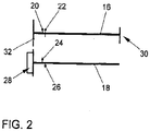
- exemplary embodiment of an internal combustion engine comprises a cylinder head 10, are integrated into the working cylinder, not shown, in each of which a reciprocating piston (not shown) oscillating between a top dead center (TDC) and bottom dead center (UT) moves.
- the cylinder head 10 includes an exhaust side 12, at which exhaust gases are discharged from the working cylinders, and an inlet side 14, at which the working cylinders fresh gas is supplied.
- Each working cylinder is associated with two intake valves (not shown) and two exhaust valves (not shown), with a fixed camshaft 16 and a variable camshaft 18 being provided.
- the fixed camshaft 16 carries intake cams 20, each actuating an intake valve, and exhaust cams 22, each actuating an exhaust valve.
- the variable camshaft 18 carries intake cams 24, each actuating an intake valve, and exhaust cams 26, each actuating an exhaust valve.
- intake cams 20, 24 and exhaust cams 22, 26 alternate as seen in the longitudinal direction. In this way, the two intake valves and exhaust valves of each working cylinder are actuated by different camshafts 16, 18.
- each of the camshafts 16, 18 is a so-called mixed camshaft, ie, each camshaft 16, 18 actuates both intake and exhaust valves via respective intake cams 20, 24 and exhaust cams 22, 26, respectively.
- the timing of the fixed camshaft 16 for the intake and exhaust valves associated therewith are fixed unchangeable.
- an adjuster 28 is arranged, via which the timing of the associated intake and exhaust valves can be changed by the second camshaft 18 is rotated by the adjuster 28.
- the fixed camshaft 16 is driven at 30 by a crankshaft, not shown, of the internal combustion engine.
- the fixed camshaft 16 in turn drives the variable camshaft 18 via gears 32.
- crankshaft angle (in ° CW) is plotted on the horizontal axis and a lifting movement (in mm) on the vertical axis.
- On the horizontal axis is at -180 ° KW, a bottom dead center (UT) of the reciprocating piston before the charge cycle, at 0 ° KW, a top dead center (TDC) of the reciprocating piston during the charge cycle and at 180 ° KW, a bottom dead center (UT) of the reciprocating after the charge change.
- a first graph 34 illustrates lift over crankshaft angle for those exhaust valves controlled by the exhaust cam 22 of the fixed camshaft 16.
- a second graph 36 (dashed) illustrates the lift over crankshaft angle for those exhaust valves controlled by the exhaust cams 26 of the variable camshaft 18.
- a third graph 38 illustrates lift over crankshaft angle for those intake valves controlled by intake cam 20 of fixed camshaft 16
- fourth graph 40 (dashed) illustrates lift over crankshaft angle for those intake valves coming in from intake lobes 24 of variable Camshaft 18 are controlled.
- Fig. 3 is shown a position of the variable camshaft with an adjustment angle of 0 ° KW, ie the camshafts 16, 18 are considered not rotated against each other.
- the exhaust valve actuated by the variable camshaft 18 opens at approximately -225 ° CA, which corresponds to 45 ° CA before the BDC of the piston.
- the corresponding exhaust valve of the fixed camshaft 16 opens at about -200 ° CA, which corresponds to 20 ° CA before UT of the piston.
- Fig. 4 is a position of the variable Nockenwelle18 shown with an adjustment angle of 10 °.
- the exhaust valve actuated by the variable camshaft 18 opens at a crankshaft angle of approximately -215 ° CA, which corresponds to 35 ° CA before UT of the piston.
- the stroke movement and thus the opening and closing shifts of the intake valve operated by the variable camshaft 18 is delayed by 10 ° with respect to the intake valve operated by the fixed camshaft 16.
- Fig. 5 is a position of the variable camshaft with an adjustment angle of about 40 °.
- the exhaust valve actuated by the variable camshaft 18 opens at a crankshaft angle of approximately -185 ° CA, which corresponds to 5 ° CA before UT of the piston.
- the stroke movement and thus the opening and closing of the intake valve operated by the variable camshaft 18 shifts 40 ° with respect to the intake valve operated by the fixed camshaft 16, late.
- the internal combustion engine in a known manner (see. DE 10 2006 042 912 A1 ) operated in a Miller cycle.
- An adjustment of the variable camshaft in an angular range of 0 ° to 5 ° is provided for a cold run of the internal combustion engine according to the invention.
- variable camshaft 18 An adjustment of the variable camshaft 18 in an angular range of 0 ° to 15 ° is provided for the full-load operation of the internal combustion engine according to the invention.
- variable camshaft 18 An adjustment of the variable camshaft 18 in an angular range of 15 ° to 50 ° is provided for operation of the internal combustion engine according to the invention with partial load.
- the expansion losses should be minimized
- the effective compression should be set at about 14 to 15 in order to reduce the emission behavior of the engine To optimize internal combustion engine.
- Fig. 6 is the course of the cylinder pressure (logarithmic, in bar) over the stroke volume (in cm 3 ) of a working cylinder of the internal combustion engine according to the invention for in the Fig. 4 and 5 illustrated adjustment positions of the variable camshaft 18 shown.
- the integral of the cylinder pressure over the stroke volume is a measure of the engine power. It can be seen that by the inventive design of the internal combustion engine with a relatively late opening of the actuated by the fixed camshaft 16 exhaust valve in conjunction with an adjustment of the actuated by the variable camshaft exhaust valve late, the engine power can be increased by 42 marked area. This increased engine power can be exploited in part-load operation for an increase in the efficiency of the internal combustion engine.
Landscapes
- Engineering & Computer Science (AREA)
- Chemical & Material Sciences (AREA)
- Combustion & Propulsion (AREA)
- Mechanical Engineering (AREA)
- General Engineering & Computer Science (AREA)
- Valve Device For Special Equipments (AREA)
- Output Control And Ontrol Of Special Type Engine (AREA)
- Valve-Gear Or Valve Arrangements (AREA)
Claims (8)
- Moteur à combustion interne avec un cylindre de travail dans lequel un piston est déplacé cycliquement entre un point mort haut (PMH) et un point mort bas (PMB), dans lequel deux soupapes d'admission et deux soupapes d'échappement sont affectées au cylindre de travail, et deux arbres à cames (16, 18) qui actionnent respectivement une soupape d'admission et une soupape d'échappement, dans lequel un arbre à cames est constitué en tant qu'arbre à cames (18) variable avec un dispositif d'avance (28) pour la commande d'avance de la distribution, et l'autre est constitué en tant qu'arbre à cames fixe avec une distribution non modifiable, caractérisé en ce que l'ouverture de la soupape d'échappement actionnée par l'arbre à cames fixe s'effectue dans une plage de 0° à 25° de rotation de vilebrequin avant le point mort bas du piston.
- Moteur à combustion interne selon la revendication 1, caractérisé en ce que l'ouverture de la soupape d'échappement actionnée par l'arbre à cames fixe s'effectue dans une plage de 10° à 20° de rotation de vilebrequin avant le PMB, et de préférence à env. 20° de rotation de vilebrequin avant le PMB.
- Moteur à combustion interne selon la revendication 1 ou 2, caractérisé en ce que le dispositif d'avance (28) est constitué de telle sorte qu'il comporte une plage de réglage d'environ 50°.
- Moteur à combustion interne selon l'une des revendications précédentes, caractérisé en ce que, dans une première position de réglage, la soupape d'échappement actionnée par l'arbre à cames (18) variable s'ouvre plus tôt que la soupape d'échappement actionnée par l'arbre à cames (16) fixe, et la soupape d'admission actionnée par l'arbre à cames (18) variable s'ouvre et se ferme en même temps que la soupape d'admission actionnée par l'arbre à cames (16) fixe.
- Moteur à combustion interne selon la revendication 4, caractérisé en ce que la soupape d'échappement affectée à l'arbre à cames variable s'ouvre à env. 45° de rotation de vilebrequin avant le PMB.
- Procédé de fonctionnement d'un moteur à combustion interne selon la revendication 4 ou 5, caractérisé en ce que pendant la marche à froid ce moteur fonctionne avec un angle de réglage de 0° à env. 5°.
- Procédé selon la revendication 6, caractérisé en ce que, en pleine charge, le moteur à combustion interne fonctionne avec un angle de réglage d'env. 0° à env. 15°.
- Procédé selon la revendication 6 ou 7, caractérisé en ce que, en charge partielle, le moteur à combustion interne fonctionne avec un angle de réglage d'env. 15° à env. 50°.
Applications Claiming Priority (1)
| Application Number | Priority Date | Filing Date | Title |
|---|---|---|---|
| DE102011103870A DE102011103870A1 (de) | 2011-06-10 | 2011-06-10 | Brennkraftmaschine |
Publications (3)
| Publication Number | Publication Date |
|---|---|
| EP2532860A2 EP2532860A2 (fr) | 2012-12-12 |
| EP2532860A3 EP2532860A3 (fr) | 2017-02-01 |
| EP2532860B1 true EP2532860B1 (fr) | 2019-10-02 |
Family
ID=46146561
Family Applications (1)
| Application Number | Title | Priority Date | Filing Date |
|---|---|---|---|
| EP12003592.8A Active EP2532860B1 (fr) | 2011-06-10 | 2012-05-08 | Moteur à combustion interne |
Country Status (2)
| Country | Link |
|---|---|
| EP (1) | EP2532860B1 (fr) |
| DE (1) | DE102011103870A1 (fr) |
Families Citing this family (1)
| Publication number | Priority date | Publication date | Assignee | Title |
|---|---|---|---|---|
| DE102012024318A1 (de) * | 2012-12-13 | 2014-06-18 | Volkswagen Aktiengesellschaft | Verfahren zum Betreiben einer Brennkraftmaschine |
Family Cites Families (6)
| Publication number | Priority date | Publication date | Assignee | Title |
|---|---|---|---|---|
| DE10359058A1 (de) * | 2003-12-17 | 2005-07-21 | Daimlerchrysler Ag | Gaswechselventilvorrichtung und Verfahren zur Betreibung derselben |
| DE102006042912A1 (de) | 2006-09-13 | 2008-03-27 | Volkswagen Ag | Brennkraftmaschine mit gemischten Nockenwellen |
| DE102007040697A1 (de) * | 2007-08-29 | 2009-03-05 | Volkswagen Ag | Brennkraftmaschine |
| DE102007046656B4 (de) * | 2007-09-28 | 2018-09-13 | Audi Ag | Verfahren zum Betreiben einer Brennkraftmaschine, Brennkraftmaschine |
| DE102007049109A1 (de) * | 2007-10-12 | 2009-04-16 | Volkswagen Ag | Brennkraftmaschine mit gemischten Nockenwellen |
| DE102009024903A1 (de) * | 2009-06-15 | 2010-12-16 | Volkswagen Ag | Verfahren zum Betreiben einer Hubkolben-Brennkraftmaschine |
-
2011
- 2011-06-10 DE DE102011103870A patent/DE102011103870A1/de not_active Withdrawn
-
2012
- 2012-05-08 EP EP12003592.8A patent/EP2532860B1/fr active Active
Non-Patent Citations (1)
| Title |
|---|
| None * |
Also Published As
| Publication number | Publication date |
|---|---|
| DE102011103870A1 (de) | 2012-12-13 |
| EP2532860A3 (fr) | 2017-02-01 |
| EP2532860A2 (fr) | 2012-12-12 |
Similar Documents
| Publication | Publication Date | Title |
|---|---|---|
| EP2048331B1 (fr) | Moteur à combustion interne doté d'arbres à came mixtes | |
| EP2066874B1 (fr) | Moteur à combustion interne à arbres à cames mixtes | |
| EP3464857B1 (fr) | Procédé de fonctionnement d'un moteur à combustion interne et moteur à combustion interne | |
| DE112014000451T5 (de) | Steuersystem für einen mit gasförmigem Kraftstoff betriebenen Motor mit Nockenphasenverschiebung zur Verbesserung des Motorstarts | |
| EP2726721B1 (fr) | Moteur a combustion interne | |
| DE10359267B4 (de) | Verbrennungsmotor mit Ansaugventilen, variabler Ventilbetätigung und Zeitsteuerung | |
| WO2018188984A1 (fr) | Procédé pour faire fonctionner un moteur à combustion interne et moteur à combustion interne | |
| WO2009030694A2 (fr) | Moteur à piston | |
| WO2013189698A1 (fr) | Procédé pour faire fonctionner un moteur à combustion interne selon le procédé d'autoallumage et moteur à combustion interne | |
| EP1331382B1 (fr) | Procédé, programme informatique et appareil de commande et/ou regulation destinés à l'utilisation d'un moteur à combustion interne, et moteur à combustion interne | |
| EP2264299A2 (fr) | Procédé destiné au fonctionnement d'un moteur à combustion interne doté d'un piston élévateur | |
| EP2500533A2 (fr) | Moteur à combustion interne doté d'un arbre à came mixte | |
| DE102014208950A1 (de) | Verbrennungsmotor und Verfahren zum Betreiben eines solchen Verbrennungsmotors | |
| EP1306527B1 (fr) | Moteur diesel à rapport de compression variable | |
| EP2532860B1 (fr) | Moteur à combustion interne | |
| EP2976512B1 (fr) | Moteur à combustion interne et procédé pour le faire fonctionner | |
| WO2016016228A1 (fr) | Moteur à combustion interne à taux de compression réglable et came d'enclenchement et procédé pour faire fonctionner un moteur à combustion interne de ce type | |
| EP2807360A1 (fr) | Dispositif de distribution à soupapes de moteur à combustion interne | |
| DE102012206683B4 (de) | Ventiltrieb für einen Zylinderkopf einer Brennkraftmaschine | |
| DE102010051832B4 (de) | Verfahren zum Betreiben einer Hubkolben-Brennkraftmaschine mit Drallbrennverfahren | |
| DE102015110558A1 (de) | Brennkraftmaschine und Verfahren zum Betreiben einer solchen Brennkraftmaschine | |
| EP3728818B1 (fr) | Procédé pour faire fonctionner un moteur à combustion interne et moteur à combustion interne | |
| DE102022212010A1 (de) | Schubbetrieb eines Verbrennungsmotors | |
| DE102007041326A1 (de) | Verfahren zum Betreiben einer Brennkraftmaschine | |
| DE102007047566A1 (de) | Verfahren zum Betrieb einer Brennkraftmaschine |
Legal Events
| Date | Code | Title | Description |
|---|---|---|---|
| PUAI | Public reference made under article 153(3) epc to a published international application that has entered the european phase |
Free format text: ORIGINAL CODE: 0009012 |
|
| AK | Designated contracting states |
Kind code of ref document: A2 Designated state(s): AL AT BE BG CH CY CZ DE DK EE ES FI FR GB GR HR HU IE IS IT LI LT LU LV MC MK MT NL NO PL PT RO RS SE SI SK SM TR |
|
| AX | Request for extension of the european patent |
Extension state: BA ME |
|
| PUAL | Search report despatched |
Free format text: ORIGINAL CODE: 0009013 |
|
| AK | Designated contracting states |
Kind code of ref document: A3 Designated state(s): AL AT BE BG CH CY CZ DE DK EE ES FI FR GB GR HR HU IE IS IT LI LT LU LV MC MK MT NL NO PL PT RO RS SE SI SK SM TR |
|
| AX | Request for extension of the european patent |
Extension state: BA ME |
|
| RIC1 | Information provided on ipc code assigned before grant |
Ipc: F02D 13/02 20060101AFI20161223BHEP |
|
| STAA | Information on the status of an ep patent application or granted ep patent |
Free format text: STATUS: REQUEST FOR EXAMINATION WAS MADE |
|
| 17P | Request for examination filed |
Effective date: 20170801 |
|
| RBV | Designated contracting states (corrected) |
Designated state(s): AL AT BE BG CH CY CZ DE DK EE ES FI FR GB GR HR HU IE IS IT LI LT LU LV MC MK MT NL NO PL PT RO RS SE SI SK SM TR |
|
| STAA | Information on the status of an ep patent application or granted ep patent |
Free format text: STATUS: EXAMINATION IS IN PROGRESS |
|
| 17Q | First examination report despatched |
Effective date: 20190104 |
|
| GRAP | Despatch of communication of intention to grant a patent |
Free format text: ORIGINAL CODE: EPIDOSNIGR1 |
|
| STAA | Information on the status of an ep patent application or granted ep patent |
Free format text: STATUS: GRANT OF PATENT IS INTENDED |
|
| INTG | Intention to grant announced |
Effective date: 20190520 |
|
| GRAS | Grant fee paid |
Free format text: ORIGINAL CODE: EPIDOSNIGR3 |
|
| GRAA | (expected) grant |
Free format text: ORIGINAL CODE: 0009210 |
|
| STAA | Information on the status of an ep patent application or granted ep patent |
Free format text: STATUS: THE PATENT HAS BEEN GRANTED |
|
| AK | Designated contracting states |
Kind code of ref document: B1 Designated state(s): AL AT BE BG CH CY CZ DE DK EE ES FI FR GB GR HR HU IE IS IT LI LT LU LV MC MK MT NL NO PL PT RO RS SE SI SK SM TR |
|
| REG | Reference to a national code |
Ref country code: GB Ref legal event code: FG4D Free format text: NOT ENGLISH |
|
| REG | Reference to a national code |
Ref country code: CH Ref legal event code: EP Ref country code: AT Ref legal event code: REF Ref document number: 1186423 Country of ref document: AT Kind code of ref document: T Effective date: 20191015 |
|
| REG | Reference to a national code |
Ref country code: DE Ref legal event code: R096 Ref document number: 502012015334 Country of ref document: DE |
|
| REG | Reference to a national code |
Ref country code: IE Ref legal event code: FG4D Free format text: LANGUAGE OF EP DOCUMENT: GERMAN |
|
| REG | Reference to a national code |
Ref country code: NL Ref legal event code: MP Effective date: 20191002 |
|
| REG | Reference to a national code |
Ref country code: LT Ref legal event code: MG4D |
|
| PG25 | Lapsed in a contracting state [announced via postgrant information from national office to epo] |
Ref country code: GR Free format text: LAPSE BECAUSE OF FAILURE TO SUBMIT A TRANSLATION OF THE DESCRIPTION OR TO PAY THE FEE WITHIN THE PRESCRIBED TIME-LIMIT Effective date: 20200103 Ref country code: PL Free format text: LAPSE BECAUSE OF FAILURE TO SUBMIT A TRANSLATION OF THE DESCRIPTION OR TO PAY THE FEE WITHIN THE PRESCRIBED TIME-LIMIT Effective date: 20191002 Ref country code: NO Free format text: LAPSE BECAUSE OF FAILURE TO SUBMIT A TRANSLATION OF THE DESCRIPTION OR TO PAY THE FEE WITHIN THE PRESCRIBED TIME-LIMIT Effective date: 20200102 Ref country code: SE Free format text: LAPSE BECAUSE OF FAILURE TO SUBMIT A TRANSLATION OF THE DESCRIPTION OR TO PAY THE FEE WITHIN THE PRESCRIBED TIME-LIMIT Effective date: 20191002 Ref country code: LV Free format text: LAPSE BECAUSE OF FAILURE TO SUBMIT A TRANSLATION OF THE DESCRIPTION OR TO PAY THE FEE WITHIN THE PRESCRIBED TIME-LIMIT Effective date: 20191002 Ref country code: PT Free format text: LAPSE BECAUSE OF FAILURE TO SUBMIT A TRANSLATION OF THE DESCRIPTION OR TO PAY THE FEE WITHIN THE PRESCRIBED TIME-LIMIT Effective date: 20200203 Ref country code: FI Free format text: LAPSE BECAUSE OF FAILURE TO SUBMIT A TRANSLATION OF THE DESCRIPTION OR TO PAY THE FEE WITHIN THE PRESCRIBED TIME-LIMIT Effective date: 20191002 Ref country code: BG Free format text: LAPSE BECAUSE OF FAILURE TO SUBMIT A TRANSLATION OF THE DESCRIPTION OR TO PAY THE FEE WITHIN THE PRESCRIBED TIME-LIMIT Effective date: 20200102 Ref country code: NL Free format text: LAPSE BECAUSE OF FAILURE TO SUBMIT A TRANSLATION OF THE DESCRIPTION OR TO PAY THE FEE WITHIN THE PRESCRIBED TIME-LIMIT Effective date: 20191002 Ref country code: LT Free format text: LAPSE BECAUSE OF FAILURE TO SUBMIT A TRANSLATION OF THE DESCRIPTION OR TO PAY THE FEE WITHIN THE PRESCRIBED TIME-LIMIT Effective date: 20191002 Ref country code: ES Free format text: LAPSE BECAUSE OF FAILURE TO SUBMIT A TRANSLATION OF THE DESCRIPTION OR TO PAY THE FEE WITHIN THE PRESCRIBED TIME-LIMIT Effective date: 20191002 |
|
| PG25 | Lapsed in a contracting state [announced via postgrant information from national office to epo] |
Ref country code: IS Free format text: LAPSE BECAUSE OF FAILURE TO SUBMIT A TRANSLATION OF THE DESCRIPTION OR TO PAY THE FEE WITHIN THE PRESCRIBED TIME-LIMIT Effective date: 20200224 Ref country code: CZ Free format text: LAPSE BECAUSE OF FAILURE TO SUBMIT A TRANSLATION OF THE DESCRIPTION OR TO PAY THE FEE WITHIN THE PRESCRIBED TIME-LIMIT Effective date: 20191002 Ref country code: HR Free format text: LAPSE BECAUSE OF FAILURE TO SUBMIT A TRANSLATION OF THE DESCRIPTION OR TO PAY THE FEE WITHIN THE PRESCRIBED TIME-LIMIT Effective date: 20191002 Ref country code: RS Free format text: LAPSE BECAUSE OF FAILURE TO SUBMIT A TRANSLATION OF THE DESCRIPTION OR TO PAY THE FEE WITHIN THE PRESCRIBED TIME-LIMIT Effective date: 20191002 |
|
| PG25 | Lapsed in a contracting state [announced via postgrant information from national office to epo] |
Ref country code: AL Free format text: LAPSE BECAUSE OF FAILURE TO SUBMIT A TRANSLATION OF THE DESCRIPTION OR TO PAY THE FEE WITHIN THE PRESCRIBED TIME-LIMIT Effective date: 20191002 |
|
| REG | Reference to a national code |
Ref country code: DE Ref legal event code: R097 Ref document number: 502012015334 Country of ref document: DE |
|
| PG2D | Information on lapse in contracting state deleted |
Ref country code: IS |
|
| PG25 | Lapsed in a contracting state [announced via postgrant information from national office to epo] |
Ref country code: DK Free format text: LAPSE BECAUSE OF FAILURE TO SUBMIT A TRANSLATION OF THE DESCRIPTION OR TO PAY THE FEE WITHIN THE PRESCRIBED TIME-LIMIT Effective date: 20191002 Ref country code: EE Free format text: LAPSE BECAUSE OF FAILURE TO SUBMIT A TRANSLATION OF THE DESCRIPTION OR TO PAY THE FEE WITHIN THE PRESCRIBED TIME-LIMIT Effective date: 20191002 Ref country code: RO Free format text: LAPSE BECAUSE OF FAILURE TO SUBMIT A TRANSLATION OF THE DESCRIPTION OR TO PAY THE FEE WITHIN THE PRESCRIBED TIME-LIMIT Effective date: 20191002 Ref country code: IS Free format text: LAPSE BECAUSE OF FAILURE TO SUBMIT A TRANSLATION OF THE DESCRIPTION OR TO PAY THE FEE WITHIN THE PRESCRIBED TIME-LIMIT Effective date: 20200202 |
|
| PLBE | No opposition filed within time limit |
Free format text: ORIGINAL CODE: 0009261 |
|
| STAA | Information on the status of an ep patent application or granted ep patent |
Free format text: STATUS: NO OPPOSITION FILED WITHIN TIME LIMIT |
|
| PG25 | Lapsed in a contracting state [announced via postgrant information from national office to epo] |
Ref country code: SM Free format text: LAPSE BECAUSE OF FAILURE TO SUBMIT A TRANSLATION OF THE DESCRIPTION OR TO PAY THE FEE WITHIN THE PRESCRIBED TIME-LIMIT Effective date: 20191002 Ref country code: IT Free format text: LAPSE BECAUSE OF FAILURE TO SUBMIT A TRANSLATION OF THE DESCRIPTION OR TO PAY THE FEE WITHIN THE PRESCRIBED TIME-LIMIT Effective date: 20191002 Ref country code: SK Free format text: LAPSE BECAUSE OF FAILURE TO SUBMIT A TRANSLATION OF THE DESCRIPTION OR TO PAY THE FEE WITHIN THE PRESCRIBED TIME-LIMIT Effective date: 20191002 |
|
| 26N | No opposition filed |
Effective date: 20200703 |
|
| PG25 | Lapsed in a contracting state [announced via postgrant information from national office to epo] |
Ref country code: SI Free format text: LAPSE BECAUSE OF FAILURE TO SUBMIT A TRANSLATION OF THE DESCRIPTION OR TO PAY THE FEE WITHIN THE PRESCRIBED TIME-LIMIT Effective date: 20191002 |
|
| PG25 | Lapsed in a contracting state [announced via postgrant information from national office to epo] |
Ref country code: LI Free format text: LAPSE BECAUSE OF NON-PAYMENT OF DUE FEES Effective date: 20200531 Ref country code: CH Free format text: LAPSE BECAUSE OF NON-PAYMENT OF DUE FEES Effective date: 20200531 Ref country code: MC Free format text: LAPSE BECAUSE OF FAILURE TO SUBMIT A TRANSLATION OF THE DESCRIPTION OR TO PAY THE FEE WITHIN THE PRESCRIBED TIME-LIMIT Effective date: 20191002 |
|
| REG | Reference to a national code |
Ref country code: BE Ref legal event code: MM Effective date: 20200531 |
|
| GBPC | Gb: european patent ceased through non-payment of renewal fee |
Effective date: 20200508 |
|
| PG25 | Lapsed in a contracting state [announced via postgrant information from national office to epo] |
Ref country code: LU Free format text: LAPSE BECAUSE OF NON-PAYMENT OF DUE FEES Effective date: 20200508 |
|
| PG25 | Lapsed in a contracting state [announced via postgrant information from national office to epo] |
Ref country code: IE Free format text: LAPSE BECAUSE OF NON-PAYMENT OF DUE FEES Effective date: 20200508 Ref country code: FR Free format text: LAPSE BECAUSE OF NON-PAYMENT OF DUE FEES Effective date: 20200531 Ref country code: GB Free format text: LAPSE BECAUSE OF NON-PAYMENT OF DUE FEES Effective date: 20200508 |
|
| PG25 | Lapsed in a contracting state [announced via postgrant information from national office to epo] |
Ref country code: BE Free format text: LAPSE BECAUSE OF NON-PAYMENT OF DUE FEES Effective date: 20200531 |
|
| REG | Reference to a national code |
Ref country code: AT Ref legal event code: MM01 Ref document number: 1186423 Country of ref document: AT Kind code of ref document: T Effective date: 20200508 |
|
| PG25 | Lapsed in a contracting state [announced via postgrant information from national office to epo] |
Ref country code: AT Free format text: LAPSE BECAUSE OF NON-PAYMENT OF DUE FEES Effective date: 20200508 |
|
| PG25 | Lapsed in a contracting state [announced via postgrant information from national office to epo] |
Ref country code: TR Free format text: LAPSE BECAUSE OF FAILURE TO SUBMIT A TRANSLATION OF THE DESCRIPTION OR TO PAY THE FEE WITHIN THE PRESCRIBED TIME-LIMIT Effective date: 20191002 Ref country code: MT Free format text: LAPSE BECAUSE OF FAILURE TO SUBMIT A TRANSLATION OF THE DESCRIPTION OR TO PAY THE FEE WITHIN THE PRESCRIBED TIME-LIMIT Effective date: 20191002 Ref country code: CY Free format text: LAPSE BECAUSE OF FAILURE TO SUBMIT A TRANSLATION OF THE DESCRIPTION OR TO PAY THE FEE WITHIN THE PRESCRIBED TIME-LIMIT Effective date: 20191002 |
|
| PG25 | Lapsed in a contracting state [announced via postgrant information from national office to epo] |
Ref country code: MK Free format text: LAPSE BECAUSE OF FAILURE TO SUBMIT A TRANSLATION OF THE DESCRIPTION OR TO PAY THE FEE WITHIN THE PRESCRIBED TIME-LIMIT Effective date: 20191002 |
|
| PGFP | Annual fee paid to national office [announced via postgrant information from national office to epo] |
Ref country code: DE Payment date: 20220531 Year of fee payment: 11 |
|
| REG | Reference to a national code |
Ref country code: DE Ref legal event code: R119 Ref document number: 502012015334 Country of ref document: DE |
|
| PG25 | Lapsed in a contracting state [announced via postgrant information from national office to epo] |
Ref country code: DE Free format text: LAPSE BECAUSE OF NON-PAYMENT OF DUE FEES Effective date: 20231201 |