EP2048331B1 - Moteur à combustion interne doté d'arbres à came mixtes - Google Patents
Moteur à combustion interne doté d'arbres à came mixtes Download PDFInfo
- Publication number
- EP2048331B1 EP2048331B1 EP20080017518 EP08017518A EP2048331B1 EP 2048331 B1 EP2048331 B1 EP 2048331B1 EP 20080017518 EP20080017518 EP 20080017518 EP 08017518 A EP08017518 A EP 08017518A EP 2048331 B1 EP2048331 B1 EP 2048331B1
- Authority
- EP
- European Patent Office
- Prior art keywords
- camshaft
- cam
- stroke
- combustion engine
- internal combustion
- Prior art date
- Legal status (The legal status is an assumption and is not a legal conclusion. Google has not performed a legal analysis and makes no representation as to the accuracy of the status listed.)
- Not-in-force
Links
- 238000002485 combustion reaction Methods 0.000 title claims description 42
- 239000007789 gas Substances 0.000 description 28
- 230000006835 compression Effects 0.000 description 18
- 238000007906 compression Methods 0.000 description 18
- 238000006073 displacement reaction Methods 0.000 description 8
- RDYMFSUJUZBWLH-UHFFFAOYSA-N endosulfan Chemical compound C12COS(=O)OCC2C2(Cl)C(Cl)=C(Cl)C1(Cl)C2(Cl)Cl RDYMFSUJUZBWLH-UHFFFAOYSA-N 0.000 description 7
- 230000009467 reduction Effects 0.000 description 3
- 230000008901 benefit Effects 0.000 description 2
- 230000005540 biological transmission Effects 0.000 description 2
- 230000008859 change Effects 0.000 description 2
- 230000002093 peripheral effect Effects 0.000 description 2
- 230000000979 retarding effect Effects 0.000 description 2
- 230000004913 activation Effects 0.000 description 1
- 239000003054 catalyst Substances 0.000 description 1
- 230000000694 effects Effects 0.000 description 1
- 239000003344 environmental pollutant Substances 0.000 description 1
- 238000010438 heat treatment Methods 0.000 description 1
- 230000014759 maintenance of location Effects 0.000 description 1
- 238000005259 measurement Methods 0.000 description 1
- 230000007246 mechanism Effects 0.000 description 1
- 238000000034 method Methods 0.000 description 1
- 230000010363 phase shift Effects 0.000 description 1
- 231100000719 pollutant Toxicity 0.000 description 1
- 230000002028 premature Effects 0.000 description 1
- 230000008569 process Effects 0.000 description 1
- 239000013589 supplement Substances 0.000 description 1
- 230000001360 synchronised effect Effects 0.000 description 1
Images



Classifications
-
- F—MECHANICAL ENGINEERING; LIGHTING; HEATING; WEAPONS; BLASTING
- F01—MACHINES OR ENGINES IN GENERAL; ENGINE PLANTS IN GENERAL; STEAM ENGINES
- F01L—CYCLICALLY OPERATING VALVES FOR MACHINES OR ENGINES
- F01L1/00—Valve-gear or valve arrangements, e.g. lift-valve gear
- F01L1/34—Valve-gear or valve arrangements, e.g. lift-valve gear characterised by the provision of means for changing the timing of the valves without changing the duration of opening and without affecting the magnitude of the valve lift
-
- F—MECHANICAL ENGINEERING; LIGHTING; HEATING; WEAPONS; BLASTING
- F01—MACHINES OR ENGINES IN GENERAL; ENGINE PLANTS IN GENERAL; STEAM ENGINES
- F01L—CYCLICALLY OPERATING VALVES FOR MACHINES OR ENGINES
- F01L1/00—Valve-gear or valve arrangements, e.g. lift-valve gear
- F01L1/02—Valve drive
-
- F—MECHANICAL ENGINEERING; LIGHTING; HEATING; WEAPONS; BLASTING
- F01—MACHINES OR ENGINES IN GENERAL; ENGINE PLANTS IN GENERAL; STEAM ENGINES
- F01L—CYCLICALLY OPERATING VALVES FOR MACHINES OR ENGINES
- F01L1/00—Valve-gear or valve arrangements, e.g. lift-valve gear
- F01L1/02—Valve drive
- F01L1/04—Valve drive by means of cams, camshafts, cam discs, eccentrics or the like
- F01L1/047—Camshafts
-
- F—MECHANICAL ENGINEERING; LIGHTING; HEATING; WEAPONS; BLASTING
- F01—MACHINES OR ENGINES IN GENERAL; ENGINE PLANTS IN GENERAL; STEAM ENGINES
- F01L—CYCLICALLY OPERATING VALVES FOR MACHINES OR ENGINES
- F01L1/00—Valve-gear or valve arrangements, e.g. lift-valve gear
- F01L1/02—Valve drive
- F01L1/04—Valve drive by means of cams, camshafts, cam discs, eccentrics or the like
- F01L1/047—Camshafts
- F01L1/053—Camshafts overhead type
-
- F—MECHANICAL ENGINEERING; LIGHTING; HEATING; WEAPONS; BLASTING
- F02—COMBUSTION ENGINES; HOT-GAS OR COMBUSTION-PRODUCT ENGINE PLANTS
- F02D—CONTROLLING COMBUSTION ENGINES
- F02D13/00—Controlling the engine output power by varying inlet or exhaust valve operating characteristics, e.g. timing
- F02D13/02—Controlling the engine output power by varying inlet or exhaust valve operating characteristics, e.g. timing during engine operation
- F02D13/0203—Variable control of intake and exhaust valves
- F02D13/0207—Variable control of intake and exhaust valves changing valve lift or valve lift and timing
-
- F—MECHANICAL ENGINEERING; LIGHTING; HEATING; WEAPONS; BLASTING
- F02—COMBUSTION ENGINES; HOT-GAS OR COMBUSTION-PRODUCT ENGINE PLANTS
- F02D—CONTROLLING COMBUSTION ENGINES
- F02D13/00—Controlling the engine output power by varying inlet or exhaust valve operating characteristics, e.g. timing
- F02D13/02—Controlling the engine output power by varying inlet or exhaust valve operating characteristics, e.g. timing during engine operation
- F02D13/0257—Independent control of two or more intake or exhaust valves respectively, i.e. one of two intake valves remains closed or is opened partially while the other is fully opened
-
- F—MECHANICAL ENGINEERING; LIGHTING; HEATING; WEAPONS; BLASTING
- F01—MACHINES OR ENGINES IN GENERAL; ENGINE PLANTS IN GENERAL; STEAM ENGINES
- F01L—CYCLICALLY OPERATING VALVES FOR MACHINES OR ENGINES
- F01L13/00—Modifications of valve-gear to facilitate reversing, braking, starting, changing compression ratio, or other specific operations
- F01L13/0015—Modifications of valve-gear to facilitate reversing, braking, starting, changing compression ratio, or other specific operations for optimising engine performances by modifying valve lift according to various working parameters, e.g. rotational speed, load, torque
- F01L2013/0089—Modifications of valve-gear to facilitate reversing, braking, starting, changing compression ratio, or other specific operations for optimising engine performances by modifying valve lift according to various working parameters, e.g. rotational speed, load, torque with means for delaying valve closing
-
- F—MECHANICAL ENGINEERING; LIGHTING; HEATING; WEAPONS; BLASTING
- F01—MACHINES OR ENGINES IN GENERAL; ENGINE PLANTS IN GENERAL; STEAM ENGINES
- F01L—CYCLICALLY OPERATING VALVES FOR MACHINES OR ENGINES
- F01L2800/00—Methods of operation using a variable valve timing mechanism
- F01L2800/16—Preventing interference
-
- F—MECHANICAL ENGINEERING; LIGHTING; HEATING; WEAPONS; BLASTING
- F02—COMBUSTION ENGINES; HOT-GAS OR COMBUSTION-PRODUCT ENGINE PLANTS
- F02D—CONTROLLING COMBUSTION ENGINES
- F02D13/00—Controlling the engine output power by varying inlet or exhaust valve operating characteristics, e.g. timing
- F02D13/02—Controlling the engine output power by varying inlet or exhaust valve operating characteristics, e.g. timing during engine operation
- F02D13/0261—Controlling the valve overlap
- F02D13/0265—Negative valve overlap for temporarily storing residual gas in the cylinder
-
- F—MECHANICAL ENGINEERING; LIGHTING; HEATING; WEAPONS; BLASTING
- F02—COMBUSTION ENGINES; HOT-GAS OR COMBUSTION-PRODUCT ENGINE PLANTS
- F02D—CONTROLLING COMBUSTION ENGINES
- F02D13/00—Controlling the engine output power by varying inlet or exhaust valve operating characteristics, e.g. timing
- F02D13/02—Controlling the engine output power by varying inlet or exhaust valve operating characteristics, e.g. timing during engine operation
- F02D13/0269—Controlling the valves to perform a Miller-Atkinson cycle
-
- F—MECHANICAL ENGINEERING; LIGHTING; HEATING; WEAPONS; BLASTING
- F02—COMBUSTION ENGINES; HOT-GAS OR COMBUSTION-PRODUCT ENGINE PLANTS
- F02M—SUPPLYING COMBUSTION ENGINES IN GENERAL WITH COMBUSTIBLE MIXTURES OR CONSTITUENTS THEREOF
- F02M26/00—Engine-pertinent apparatus for adding exhaust gases to combustion-air, main fuel or fuel-air mixture, e.g. by exhaust gas recirculation [EGR] systems
- F02M26/01—Internal exhaust gas recirculation, i.e. wherein the residual exhaust gases are trapped in the cylinder or pushed back from the intake or the exhaust manifold into the combustion chamber without the use of additional passages
-
- Y—GENERAL TAGGING OF NEW TECHNOLOGICAL DEVELOPMENTS; GENERAL TAGGING OF CROSS-SECTIONAL TECHNOLOGIES SPANNING OVER SEVERAL SECTIONS OF THE IPC; TECHNICAL SUBJECTS COVERED BY FORMER USPC CROSS-REFERENCE ART COLLECTIONS [XRACs] AND DIGESTS
- Y02—TECHNOLOGIES OR APPLICATIONS FOR MITIGATION OR ADAPTATION AGAINST CLIMATE CHANGE
- Y02T—CLIMATE CHANGE MITIGATION TECHNOLOGIES RELATED TO TRANSPORTATION
- Y02T10/00—Road transport of goods or passengers
- Y02T10/10—Internal combustion engine [ICE] based vehicles
- Y02T10/12—Improving ICE efficiencies
Definitions
- the invention relates to an internal combustion engine, in particular a diesel engine, in particular a motor vehicle, with at least one working cylinder, wherein each working cylinder at least a first inlet valve and at least a second inlet valve and at least a first exhaust valve and at least one second exhaust valve are assigned, wherein a first camshafts is provided which actuates the first intake valves and the first exhaust valves of each working cylinder, wherein a second camshaft is provided, which actuates the second intake valves and the second exhaust valves of each working cylinder, wherein on the second camshaft, a phaser is arranged, which valve timing associated with said second camshaft Inlet and exhaust valves with respect to the valve timing of the first camshaft selectively adjusted to early or late, each cam on its peripheral contour has a main survey such that the d associated with this cam gas exchange valve performs a main lift, according to the preamble of claim 1.
- From the DE 10 2005 031 241 A1 is a piston internal combustion engine of a motor vehicle with a control for cyclically synchronous and cylinder-selective switching from spark ignition to controlled auto-ignition and vice versa known, wherein a valve group of a cylinder has a plurality of inlet and outlet valves and an opening period of the valve group is divided differently on inlet and outlet valves.
- a reciprocating internal combustion engine with switching cam wherein gas inlet valves and gas outlet valves are provided, which are actuated via at least one camshaft.
- the camshaft has at least one cam as a control contour.
- the cam has a base circle contour with a radially outwardly projecting cam contour of the base circle contour.
- a contoured body with an additional cam structure has a rest position, which is simultaneously its active position, wherein the contoured body protrudes in its rest position permanently yielding protrudes over the base circle contour and is pressed radially into its base circle contour when driving over with a power transmission member and blocked in its active position, the permanent compliance is.
- the contoured body is completely pressed radially.
- the power transmission member is, for example, a roller suspended from a valvetrain.
- the contoured body allows in its active position an internal exhaust gas recirculation. Preferably, this is over a Controlled engine, which receives for a corresponding activation measurement and operating data not only from the internal combustion engine, but also from the exhaust system and evaluates.
- the document EP 1 242 720 A1 relates to a four-stroke internal combustion engine with two camshafts, wherein at least one camshaft is adjusted by a phaser with respect to the phase position with respect to a crankshaft. All intake valves are actuated by a camshaft, so that a change in the phase angle of this camshaft relative to the crankshaft transmits to all intake valves in the same way.
- WO 2006/014098 A1 discloses a gas exchange valve mechanism of an internal combustion engine with two camshafts, both of which are adjusted by a centrifugal force regulator in dependence on the rotational speed of the internal combustion engine.
- the document WO 02/29214 A1 relates to a control for gas exchange valves of an internal combustion engine with two camshafts. One of the two camshafts is adjusted by a phaser relative to the other camshaft.
- the invention is based on the object, an internal combustion engine og. Type with regard to the control of gas exchange valves to improve.
- At least one cam of the first or second camshaft is formed such that the course of the main lift over the crank angle of the cam associated gas exchange valve is selectively or permanently changed in its amplitude and / or time length with respect to the crank angle.
- At least one cam of the second camshaft has at least one additional elevation which is arranged and configured in such a way that the gas exchange valve assigned to this cam carries out an additional stroke in addition to the main stroke before the beginning and / or at or after the end of the main stroke , wherein the additional stroke is smaller than the main stroke.
- a simple representation of a Miller cycle and an internal exhaust gas recirculation over a variability of the intake valve is achieved in that at least one cam of the second cam shaft, which actuates a second intake valve, the additional elevation is arranged and designed such that this second intake valve before Beginning of the main stroke executes the additional stroke.
- the additional stroke is for example 0.5 mm to 2 mm.
- a simple representation of a Miller cycle and an internal exhaust gas recirculation over a variability of the exhaust valve is achieved by the fact that in at least one cam of the second cam shaft, which actuates a second exhaust valve, the additional survey is arranged and designed such that this second exhaust valve executes the additional stroke at the end of the main stroke, which extends with respect to the crank angle beyond the end of the main stroke.
- the additional stroke extends beyond the beginning of the main lift of the second intake valve relative to the crank angle.
- the additional stroke is for example 0.5 mm to 2 mm.
- a simple representation of a Miller cycle and an internal exhaust gas recirculation over a variability of the exhaust valve is achieved in that at least one cam of the first camshaft which actuates a first exhaust valve of a working cylinder, is designed such that this cam optionally the first exhaust valve with the main stroke actuated; the main stroke of this first exhaust valve is lowered to zero or the course of the main stroke in relation to the crank angle in amplitude and phase is identical to the main stroke of the second exhaust valve of this working cylinder.
- the at least one cam of the first camshaft which actuates a first exhaust valve of a working cylinder has two cam contours, wherein a cam contour corresponds to that of the cam of the second camshaft for the second exhaust valves.
- an inventive internal combustion engine comprises a cylinder head 10, are arranged in the non-illustrated working cylinder, in which each have a reciprocating piston (not shown) oscillating moves.
- the cylinder head 10 has an outlet side 12, at which exhaust gases are discharged from the working cylinders, and an inlet side 14, at which the working cylinders fresh gas is supplied.
- Each cylinder is associated with two intake valves (not shown) and two exhaust valves (not shown), wherein a first camshaft 16 and a second camshaft 18 are provided.
- the first camshaft 16 carries first intake cams 20, each actuating a first intake valve, and first exhaust cams 22, each actuating a first exhaust valve.
- the second camshaft 18 carries second intake cams 24, each actuating a second intake valve, and second exhaust cams 26 each actuating a second exhaust valve.
- first and second intake cams 20, 24 and first and second exhaust cams 22, 26 alternate as seen in the longitudinal direction. In this way, the two intake valves and exhaust valves of each working cylinder are actuated by different camshafts 16, 18.
- each of the camshafts 12, 14 is a so-called mixed camshaft, ie, each camshaft 12, 14 actuates both intake and exhaust valves via respective intake cams 20, 24 and exhaust cams 22, 26, respectively.
- the timing of the first camshaft 16 for the associated intake and exhaust valves are fixed unchangeable.
- a phaser 28 which changes the timing of the intake and exhaust valves associated therewith with respect to the timing of the first camshaft 16 by rotating the second camshaft 18 by the phaser 28 relative to the first camshaft 16.
- the first camshaft 16 is the camshaft that is driven at 30 by a crankshaft, not shown, of the internal combustion engine.
- the first camshaft 16 in turn drives the second camshaft 18 via gears 32.
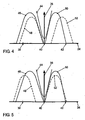
- a lifting movement applied On the horizontal axis 34 is at 38 a bottom dead center (UT) of the reciprocating piston after the power stroke and before the charge cycle, at 40 is an upper dead center (TDC) of the reciprocating piston during the charge cycle and at 42 is a bottom dead center (UT) of the reciprocating piston applied after the charge change and before the compression stroke.
- UT bottom dead center
- TDC upper dead center
- UT bottom dead center
- a first graph 44 illustrates the lift 36 across the crank angle 34 for the piston
- a second graph 46 illustrates the lift 36 over the crank angle 34 for those first exhaust valves controlled by the first exhaust cams 22 of the first cam 16
- a third graph 48 (Dashed) illustrates the lifting movement 36 over the crank angle 34 for those second exhaust valves
- a fourth graph 50 illustrates the lift 36 over the crank angle 34 for those first intake valves controlled by the first intake cams 20 of the first camshaft 16
- a fifth graph 52 (dashed) illustrates the lift 36 over the crank angle 34 for those second intake valves that are controlled by the second intake cam 24 of the second camshaft 18.
- Fig. 3 is a position of the adjuster 28 shown at 0 ° KW, ie, the camshafts 16, 18 are not rotated against each other.
- Fig. 4 is a position of the adjuster 28 at maximum displacement towards late and in Fig. 5 is shown a position of the adjuster 28 at maximum adjustment in the direction early.
- the lifting movement of the first gas exchange valves of the first crankshaft 16 (second graph 46 and fourth graph 50) remains unchanged relative to the crankshaft, whereas the lifting movement of the second gas exchange valves of the second crankshaft 18 (third graph 48 and fifth graph 52 each dashed) in common for the associated second intake valves and second exhaust valves are moved.
- a millereffect can be simulated by the shifted opening times between the first intake valves of the first crankshaft 16 (intake cam 20, fourth graph 50) and the second intake valves of the second crankshaft 18 (intake cam 24, fifth graph 52).
- Fig. 3 On the other hand, a collision between the intake valves and the reciprocating piston is prevented.
- the prerequisite for this simulated Miller is the presence of at least two intake valves per cylinder and two exhaust valves per cylinder, with the intake valves of each cylinder being actuated by different crankshafts.
- the first camshaft 16 serves half of all intake and exhaust valves with conventional timing.
- the second camshaft 18 operates the remaining second inlet and outlet valves and is with respect to the cam contour for "exhaust valve closes” and “inlet valve opens” designed so that an adjustment of this camshaft 18 of about 60 ° CA +/- 20 ° take place without piston collision can.
- the Miller effect is achieved by associating the earliest "intake valve open" of the first camshaft 16 and the latest “intake valve closing" of the second camshaft 18 with different valves for each power cylinder, cf. Fig. 4 ,
- ES approx.
- UT 42 in order to achieve the maximum compression ratio with advance adjustment of the second camshaft 18.
- this can also be considered as 0 ° position for the second camshaft 18, so that then only a retardation occurs.
- the first intake cam of the first camshaft 16 is shortened to about 10 ° -25 ° CA to UT in comparison to ES, for example in diesel engines such that the UT position ES can be achieved by both cams ,
- a so-called "boot phase” This is in 6 and 7 illustrates where Fig. 6 a state with maximum adjustment to late and Fig. 7 shows a state with maximum adjustment to early.
- the course of the stroke 52 of the second inlet valve is supplemented by a "boot ramp" 54.
- the additional increase precedes the main survey.
- FIG. 10 illustrates a load speed map 60 for an internal combustion engine according to the first preferred embodiment.
- On a horizontal axis 56 is a speed in rpm and on a vertical axis 58 is a load in percent of the maximum load of the internal combustion engine.
- the map 60 is divided by a first line 62 into a first map area 64 and a second map area 66, and by a second line 68 into the second map area 66 and a third map area 70.
- the second camshaft increases in the direction of arrow 72 due to retardation 18 realized an increasing compression reduction.
- Late closure of the second inlet valve to UT 42 results in a Miller-Atkinson cycle.
- the effective compression ratio is smaller than the geometric compression ratio. This leads to a corresponding reduction of pollutant emissions.
- the adjuster 28 is in a position in which the phase shift between the first and second camshaft 16, 18 is 0 ° CA.
- the compression ratio increasingly corresponds to the geometric compression ratio of the working cylinder.
- the second camshaft 18 is displaced maximally early, so that both intake valves 16, 18 close at UT 42.
- the compression ratio corresponds to the geometric compression ratio of the working cylinder.
- the second camshaft 18 is maximally advanced and there is a maximum internal exhaust gas recirculation (EGR).
- EGR exhaust gas recirculation
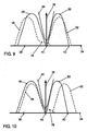
- FIGS. 9 and 10 illustrate a stroke course of the intake and exhaust valves for a second preferred embodiment of the internal combustion engine according to the invention.
- the load range of the engine operation by an appropriate cam shape of an inner EGR has been realized via the second intake valve
- FIGS. 9 and 10 realized an additional internal exhaust gas recirculation (EGR) via the second exhaust valve.
- EGR exhaust gas recirculation
- a trailing ramp or additional elevation with a lifting height of, for example, about 0.5 to 2 mm provided.
- FIGS. 9 and 10 apparent trailing ramp or an additional stroke 76 of the Ventilhubverlaufes 48 of the second exhaust valve.
- Fig. 9 shows the state with maximum advance
- Fig. 10 shows the state with maximum retardation of the second camshaft 18th
- the second exhaust valve actuated via this second exhaust cam 26 remains open in the intake stroke of the engine after TDC 40. This leads to a suction of a portion of the previously ejected exhaust gas parallel to the fresh air in the intake stroke between OT 40 and UT 42 until the second exhaust valve at the end of the additional stroke 76 closes.
- a corresponding valve pocket is provided in the piston at the position of the variable second exhaust valve.
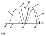
- Fig. 11 illustrate a stroke course of the intake and exhaust valves for a third preferred embodiment of the internal combustion engine according to the invention. This results in an advance of the adjuster 28 and the second camshaft 18, a negative valve overlap (residual gas retention), which also corresponds to a fast internal EGR.
- the first exhaust cam 22 of the first camshaft 16 is supplemented by an additional control per cylinder or summarized on the side of the first camshaft 16 is switched over or switched off.
- the control of the residual gas content then takes place by means of the adjustable second camshaft 18 by displacement of outlet closes in the direction of early or late.
- the first exhaust cam 22 is reduced to at least the geometry and position of the variable second exhaust cam 26 by the switching operation.
- Fig. 11 shows the state with switched off the first exhaust cam 22 (stroke 46 is missing).
- the Ventilhubverlauf 46 of the first exhaust valve is lowered to zero, ie, the first exhaust valve remains closed and the outlet closes in accordance with the stroke 48 before the TDC 40, ie before the complete expulsion of the exhaust gas from the cylinder and before the opening of the first intake valve with the stroke 50 and before opening the second inlet valve with the stroke 52.
- an additional shutdown of the fixed first inlet cam 20 recovers a part of the compression losses of the exhaust gas incurred in the first case. This would be in Fig. 11 Also, the stroke curve 50 of the first intake valve disappear or reduced to zero, so that there is an even greater negative valve overlap.
- the closing of the second exhaust valve takes place by exactly the same amount of the crank angle before TDC 40 as the first opening of one of the intake valves (stroke profile 50 or 52) after TDC 40.
- the Fig. 6, 7 . 9 and 10 generally relate to a variable valve train (VVT) internal combustion engine, whereas the Fig. 11 specifically relates to an internal combustion engine with phaser.
- VVT variable valve train
Landscapes
- Engineering & Computer Science (AREA)
- Mechanical Engineering (AREA)
- General Engineering & Computer Science (AREA)
- Chemical & Material Sciences (AREA)
- Combustion & Propulsion (AREA)
- Valve Device For Special Equipments (AREA)
- Valve-Gear Or Valve Arrangements (AREA)
- Output Control And Ontrol Of Special Type Engine (AREA)
Claims (11)
- Moteur à combustion interne comprenant au moins un cylindre de travail, au moins une première soupape d'admission et au moins une deuxième soupape d'admission ainsi qu'au moins une première soupape d'échappement et au moins une deuxième soupape d'échappement étant associées à chaque cylindre de travail, un premier arbre à cames (16) étant prévu, lequel actionne les premières soupapes d'admission et les premières soupapes d'échappement de chaque cylindre de travail, un deuxième arbre à cames (18) étant prévu, lequel actionne les deuxièmes soupapes d'admission et les deuxièmes soupapes d'échappement de chaque cylindre de travail, un dispositif de réglage (28) étant disposé sur le deuxième arbre à cames (18), lequel dispositif de réglage règle de manière sélective en avance ou en retard les temps de commande de soupape des soupapes d'admission et d'échappement associées à ce deuxième arbre à cames (18) par rapport aux temps de commande de soupape du premier arbre à cames (16), chaque came (20, 22, 24, 26) comprenant sur son contour périphérique un bossage principal de telle sorte que la soupape d'échange de gaz associée à cette came effectue une course principale (46, 48, 50, 52), caractérisé en ce qu'au moins une came (24, 26) du deuxième arbre à cames (18) comprend au moins un bossage supplémentaire qui est disposé et réalisé de telle sorte que la soupape d'échange de gaz associée à cette came (24, 26) effectue, en plus de la course principale (48, 52), une course supplémentaire (54, 76) avant le début et/ou à ou après la fin de la course principale (48, 52), la course supplémentaire (54, 76) étant plus petite que la course principale (48, 52).
- Moteur à combustion interne selon la revendication 1, caractérisé en ce qu'en cas d'au moins une came (24) du deuxième arbre à cames (18) qui actionne une deuxième soupape d'admission, le bossage supplémentaire est disposé et réalisé de telle sorte que cette deuxième soupape d'admission effectue la course supplémentaire (54) avant le début de la course principale (52).
- Moteur à combustion interne selon la revendication 2, caractérisé en ce que la course supplémentaire (54) vaut de 0,5 mm à 2 mm.
- Moteur à combustion interne selon au moins l'une quelconque des revendications 1 à 3, caractérisé en ce, qu'en cas d'au moins une came (26) du deuxième arbre à cames (18) qui actionne une deuxième soupape d'échappement, le bossage supplémentaire est disposé et réalisé de telle sorte que cette deuxième soupape d'échappement effectue la course supplémentaire (76) à la fin de la course principale (48), laquelle course supplémentaire s'étend au-delà de la fin de la course principale (48) par rapport à l'angle de vilebrequin (34).
- Moteur à combustion interne selon la revendication 4, caractérisé en ce que la course supplémentaire (76) s'étend au-delà du commencement de la course principale (52) de la deuxième soupape d'admission par rapport à l'angle de vilebrequin.
- Moteur à combustion interne selon la revendication 4 ou 5, caractérisé en ce que la course supplémentaire (76) vaut de 0,5 mm à 2 mm.
- Moteur à combustion interne selon au moins l'une quelconque des revendications précédentes, caractérisé en ce qu'au moins une came (22) du premier arbre à cames (16) qui actionne une première soupape d'échappement d'un cylindre de travail est réalisée de telle sorte que cette came (22) actionne de manière sélective la première soupape d'échappement avec la course principale (46), la course principale (46) de cette première soupape d'échappement s'abaisse jusqu'à zéro ou la variation de la course principale (46) par rapport à l'angle de vilebrequin (34) est identique en amplitude et en phase à la course principale (48) de la deuxième soupape d'échappement de ce cylindre de travail.
- Moteur à combustion interne selon la revendication 7, caractérisé en ce que l'au moins une came (22) du premier arbre à cames (16) qui actionne une première soupape d'échappement d'un cylindre de travail comprend deux contours de came, un contour de came correspondant à ceux des cames du deuxième arbre à cames (18) pour les deuxièmes soupapes d'échappement.
- Moteur à combustion interne selon la revendication 8, caractérisé en ce qu'un dispositif est prévu pour commuter entre les deux contours de came.
- Moteur à combustion interne selon l'une quelconque des revendications précédentes, caractérisé en ce que le moteur à combustion interne est un moteur Diesel.
- Moteur à combustion interne selon l'une quelconque des revendications précédentes, caractérisé en ce que le moteur à combustion interne est un moteur à combustion interne d'un véhicule automobile.
Applications Claiming Priority (1)
| Application Number | Priority Date | Filing Date | Title |
|---|---|---|---|
| DE200710049109 DE102007049109A1 (de) | 2007-10-12 | 2007-10-12 | Brennkraftmaschine mit gemischten Nockenwellen |
Publications (3)
| Publication Number | Publication Date |
|---|---|
| EP2048331A2 EP2048331A2 (fr) | 2009-04-15 |
| EP2048331A3 EP2048331A3 (fr) | 2011-07-20 |
| EP2048331B1 true EP2048331B1 (fr) | 2013-07-17 |
Family
ID=40307543
Family Applications (1)
| Application Number | Title | Priority Date | Filing Date |
|---|---|---|---|
| EP20080017518 Not-in-force EP2048331B1 (fr) | 2007-10-12 | 2008-10-07 | Moteur à combustion interne doté d'arbres à came mixtes |
Country Status (2)
| Country | Link |
|---|---|
| EP (1) | EP2048331B1 (fr) |
| DE (1) | DE102007049109A1 (fr) |
Cited By (1)
| Publication number | Priority date | Publication date | Assignee | Title |
|---|---|---|---|---|
| DE102020101552A1 (de) | 2020-01-23 | 2021-07-29 | Bayerische Motoren Werke Aktiengesellschaft | Verfahren zum Betreiben einer fremd gezündeten Hubkolben-Brennkraftmaschine |
Families Citing this family (12)
| Publication number | Priority date | Publication date | Assignee | Title |
|---|---|---|---|---|
| JP5447692B2 (ja) * | 2010-12-16 | 2014-03-19 | トヨタ自動車株式会社 | 内燃機関の吸気装置 |
| DE102011014308A1 (de) * | 2011-03-18 | 2012-09-20 | Volkswagen Aktiengesellschaft | Brennkraftmaschine mit gemischter Nockenwelle |
| DE102011103870A1 (de) * | 2011-06-10 | 2012-12-13 | Volkswagen Aktiengesellschaft | Brennkraftmaschine |
| DE102011106394A1 (de) * | 2011-07-02 | 2013-01-03 | Volkswagen Aktiengesellschaft | Brennkraftmaschine |
| DE102012006982A1 (de) | 2012-04-05 | 2013-10-10 | Kolbenschmidt Pierburg Innovations Gmbh | Mechanisch steuerbarer Ventiltrieb mit einem Gasauslassventil sowie mechanisch steuerbare Ventiltriebanordnung und Brennkraftmaschine |
| GB2501311B (en) * | 2012-04-20 | 2014-08-13 | Ford Global Tech Llc | Camshaft for the exhaust side of a multiple-cylinder four-stroke internal combustion engine |
| DE102013004800A1 (de) * | 2013-03-20 | 2014-09-25 | Volkswagen Aktiengesellschaft | Brennkraftmaschine und Verfahren zum Betreiben einer solchen Brennkraftmaschine |
| DE102013007270A1 (de) * | 2013-04-26 | 2014-10-30 | Daimler Ag | Ventiltriebvorrichtung für eine Brennkraftmaschine |
| EP3245394B1 (fr) | 2014-12-08 | 2019-08-07 | Wärtsilä Finland Oy | Procédé de contrôle de fonctionnement d'un système de soupape d'admission et système de contrôle de soupape d'admission |
| CN110719991B (zh) * | 2017-04-28 | 2023-05-09 | 伊顿智能动力有限公司 | 通过靴形气门升程曲线进行后处理温度管理 |
| DE102019124961B4 (de) * | 2019-09-17 | 2023-05-25 | Bayerische Motoren Werke Aktiengesellschaft | Antriebsanordnung mit schaltbaren Auslassventilen |
| DE102019133590A1 (de) | 2019-12-09 | 2021-06-10 | Bayerische Motoren Werke Aktiengesellschaft | Hubsteller für einen hubvariablen Ventiltrieb mit zwei Arbeitslagen |
Family Cites Families (5)
| Publication number | Priority date | Publication date | Assignee | Title |
|---|---|---|---|---|
| SE522080C2 (sv) | 1999-12-13 | 2004-01-13 | Volvo Car Corp | Fyrtakts förbränningsmotor med variabla kamtider |
| US7146949B2 (en) | 2000-09-29 | 2006-12-12 | Edward Charles Mendler | Valve control apparatus |
| DE10337430A1 (de) | 2003-08-13 | 2005-03-17 | Fev Motorentechnik Gmbh | Verbrennungskraftmaschine mit Schaltnocken |
| LV13238B (en) | 2004-08-06 | 2004-12-20 | Arnis Treijs | Mechanical device for distribution of gases that automatically changes phases of intake/exhaust depending of workload and speed of engine |
| DE102005031241A1 (de) | 2005-07-01 | 2007-01-04 | Fev Motorentechnik Gmbh | Variabler Ventiltrieb einer Kolben-Brennkraftmaschine |
-
2007
- 2007-10-12 DE DE200710049109 patent/DE102007049109A1/de not_active Withdrawn
-
2008
- 2008-10-07 EP EP20080017518 patent/EP2048331B1/fr not_active Not-in-force
Cited By (1)
| Publication number | Priority date | Publication date | Assignee | Title |
|---|---|---|---|---|
| DE102020101552A1 (de) | 2020-01-23 | 2021-07-29 | Bayerische Motoren Werke Aktiengesellschaft | Verfahren zum Betreiben einer fremd gezündeten Hubkolben-Brennkraftmaschine |
Also Published As
| Publication number | Publication date |
|---|---|
| EP2048331A2 (fr) | 2009-04-15 |
| EP2048331A3 (fr) | 2011-07-20 |
| DE102007049109A1 (de) | 2009-04-16 |
Similar Documents
| Publication | Publication Date | Title |
|---|---|---|
| EP2048331A2 (fr) | Moteur à combustion interne doté d'arbres à came mixtes | |
| EP3464857B1 (fr) | Procédé de fonctionnement d'un moteur à combustion interne et moteur à combustion interne | |
| DE102005031241A1 (de) | Variabler Ventiltrieb einer Kolben-Brennkraftmaschine | |
| EP3610147B1 (fr) | Procédé pour faire fonctionner un moteur à combustion interne et moteur à combustion interne | |
| EP2183469B1 (fr) | Moteur à piston | |
| EP2726721B1 (fr) | Moteur a combustion interne | |
| EP2500533B1 (fr) | Moteur à combustion interne doté d'un arbre à came mixte | |
| DE102005015853A1 (de) | Verfahren zum Betrieb einer Hubkolbenbrennkraftmaschine mit einer internen und externen Abgasrückführung | |
| DE102005015852A1 (de) | Hubkolbenbrennkraftmaschine | |
| EP3008300B1 (fr) | Moteur a combustion interne et procédé pour changer le mode de fonctionnement du moteur et passer d'un fonctionnement normal à un mode de fonctionnement avec balayage | |
| DE102010033493A1 (de) | Brennkraftmaschine und Verfahren zum Betreiben einer Brennkraftmaschine | |
| DE102006042912A1 (de) | Brennkraftmaschine mit gemischten Nockenwellen | |
| EP3536917B1 (fr) | Mécanisme de soupapes variable pourvu de système de cames coulissantes pour un moteur à combustion interne | |
| EP2976512B1 (fr) | Moteur à combustion interne et procédé pour le faire fonctionner | |
| DE102015205297A1 (de) | Brennkraftmaschine | |
| EP2031196A2 (fr) | Moteur à combustion interne | |
| WO2013110429A1 (fr) | Dispositif de distribution à soupapes de moteur à combustion interne | |
| DE102006002133B4 (de) | Ventiltrieb zur hubvariablen Betätigung eines Gaswechselventils einer Brennkraftmaschine | |
| DE102004005588A1 (de) | Schaltbare Nockenwelle zur Änderung der Nockenerhebungsdauer | |
| EP1342897B1 (fr) | Commande de soupape variable pour moteur à quatre temps à allumage par étincelle | |
| EP2532860B1 (fr) | Moteur à combustion interne | |
| DE202015106072U1 (de) | Brennkraftmaschine mit variablem Ventiltrieb | |
| EP3728818A1 (fr) | Procédé pour faire fonctionner un moteur à combustion interne et moteur à combustion interne | |
| DE102016219079A1 (de) | Fremdgezündete Brennkraftmaschine mit variablem Ventiltrieb und Verfahren zum Betreiben einer derartigen Brennkraftmaschine | |
| WO2014173480A1 (fr) | Dispositif de commande de soupapes pour moteur à combustion interne |
Legal Events
| Date | Code | Title | Description |
|---|---|---|---|
| PUAI | Public reference made under article 153(3) epc to a published international application that has entered the european phase |
Free format text: ORIGINAL CODE: 0009012 |
|
| AK | Designated contracting states |
Kind code of ref document: A2 Designated state(s): AT BE BG CH CY CZ DE DK EE ES FI FR GB GR HR HU IE IS IT LI LT LU LV MC MT NL NO PL PT RO SE SI SK TR |
|
| AX | Request for extension of the european patent |
Extension state: AL BA MK RS |
|
| PUAL | Search report despatched |
Free format text: ORIGINAL CODE: 0009013 |
|
| AK | Designated contracting states |
Kind code of ref document: A3 Designated state(s): AT BE BG CH CY CZ DE DK EE ES FI FR GB GR HR HU IE IS IT LI LT LU LV MC MT NL NO PL PT RO SE SI SK TR |
|
| AX | Request for extension of the european patent |
Extension state: AL BA MK RS |
|
| 17P | Request for examination filed |
Effective date: 20120120 |
|
| 17Q | First examination report despatched |
Effective date: 20120216 |
|
| AKX | Designation fees paid |
Designated state(s): AT BE BG CH CY CZ DE DK EE ES FI FR GB GR HR HU IE IS IT LI LT LU LV MC MT NL NO PL PT RO SE SI SK TR |
|
| RAP1 | Party data changed (applicant data changed or rights of an application transferred) |
Owner name: VOLKSWAGEN AKTIENGESELLSCHAFT |
|
| REG | Reference to a national code |
Ref country code: DE Ref legal event code: R079 Ref document number: 502008010310 Country of ref document: DE Free format text: PREVIOUS MAIN CLASS: F01L0001340000 Ipc: F01L0001020000 |
|
| GRAP | Despatch of communication of intention to grant a patent |
Free format text: ORIGINAL CODE: EPIDOSNIGR1 |
|
| RIC1 | Information provided on ipc code assigned before grant |
Ipc: F01L 1/047 20060101ALI20130121BHEP Ipc: F01L 1/02 20060101AFI20130121BHEP Ipc: F01L 1/053 20060101ALI20130121BHEP Ipc: F02D 13/02 20060101ALI20130121BHEP Ipc: F01L 1/34 20060101ALI20130121BHEP |
|
| GRAS | Grant fee paid |
Free format text: ORIGINAL CODE: EPIDOSNIGR3 |
|
| GRAA | (expected) grant |
Free format text: ORIGINAL CODE: 0009210 |
|
| AK | Designated contracting states |
Kind code of ref document: B1 Designated state(s): AT BE BG CH CY CZ DE DK EE ES FI FR GB GR HR HU IE IS IT LI LT LU LV MC MT NL NO PL PT RO SE SI SK TR |
|
| REG | Reference to a national code |
Ref country code: GB Ref legal event code: FG4D Free format text: NOT ENGLISH |
|
| REG | Reference to a national code |
Ref country code: CH Ref legal event code: EP |
|
| REG | Reference to a national code |
Ref country code: IE Ref legal event code: FG4D Free format text: LANGUAGE OF EP DOCUMENT: GERMAN |
|
| REG | Reference to a national code |
Ref country code: AT Ref legal event code: REF Ref document number: 622373 Country of ref document: AT Kind code of ref document: T Effective date: 20130815 |
|
| REG | Reference to a national code |
Ref country code: DE Ref legal event code: R096 Ref document number: 502008010310 Country of ref document: DE Effective date: 20130912 |
|
| REG | Reference to a national code |
Ref country code: NL Ref legal event code: VDEP Effective date: 20130717 |
|
| REG | Reference to a national code |
Ref country code: LT Ref legal event code: MG4D |
|
| PG25 | Lapsed in a contracting state [announced via postgrant information from national office to epo] |
Ref country code: SE Free format text: LAPSE BECAUSE OF FAILURE TO SUBMIT A TRANSLATION OF THE DESCRIPTION OR TO PAY THE FEE WITHIN THE PRESCRIBED TIME-LIMIT Effective date: 20130717 Ref country code: LT Free format text: LAPSE BECAUSE OF FAILURE TO SUBMIT A TRANSLATION OF THE DESCRIPTION OR TO PAY THE FEE WITHIN THE PRESCRIBED TIME-LIMIT Effective date: 20130717 Ref country code: IS Free format text: LAPSE BECAUSE OF FAILURE TO SUBMIT A TRANSLATION OF THE DESCRIPTION OR TO PAY THE FEE WITHIN THE PRESCRIBED TIME-LIMIT Effective date: 20131117 Ref country code: CY Free format text: LAPSE BECAUSE OF FAILURE TO SUBMIT A TRANSLATION OF THE DESCRIPTION OR TO PAY THE FEE WITHIN THE PRESCRIBED TIME-LIMIT Effective date: 20130731 Ref country code: PT Free format text: LAPSE BECAUSE OF FAILURE TO SUBMIT A TRANSLATION OF THE DESCRIPTION OR TO PAY THE FEE WITHIN THE PRESCRIBED TIME-LIMIT Effective date: 20131118 Ref country code: NO Free format text: LAPSE BECAUSE OF FAILURE TO SUBMIT A TRANSLATION OF THE DESCRIPTION OR TO PAY THE FEE WITHIN THE PRESCRIBED TIME-LIMIT Effective date: 20131017 Ref country code: HR Free format text: LAPSE BECAUSE OF FAILURE TO SUBMIT A TRANSLATION OF THE DESCRIPTION OR TO PAY THE FEE WITHIN THE PRESCRIBED TIME-LIMIT Effective date: 20130717 |
|
| PG25 | Lapsed in a contracting state [announced via postgrant information from national office to epo] |
Ref country code: SI Free format text: LAPSE BECAUSE OF FAILURE TO SUBMIT A TRANSLATION OF THE DESCRIPTION OR TO PAY THE FEE WITHIN THE PRESCRIBED TIME-LIMIT Effective date: 20130717 Ref country code: PL Free format text: LAPSE BECAUSE OF FAILURE TO SUBMIT A TRANSLATION OF THE DESCRIPTION OR TO PAY THE FEE WITHIN THE PRESCRIBED TIME-LIMIT Effective date: 20130717 Ref country code: FI Free format text: LAPSE BECAUSE OF FAILURE TO SUBMIT A TRANSLATION OF THE DESCRIPTION OR TO PAY THE FEE WITHIN THE PRESCRIBED TIME-LIMIT Effective date: 20130717 Ref country code: GR Free format text: LAPSE BECAUSE OF FAILURE TO SUBMIT A TRANSLATION OF THE DESCRIPTION OR TO PAY THE FEE WITHIN THE PRESCRIBED TIME-LIMIT Effective date: 20131018 Ref country code: LV Free format text: LAPSE BECAUSE OF FAILURE TO SUBMIT A TRANSLATION OF THE DESCRIPTION OR TO PAY THE FEE WITHIN THE PRESCRIBED TIME-LIMIT Effective date: 20130717 Ref country code: NL Free format text: LAPSE BECAUSE OF FAILURE TO SUBMIT A TRANSLATION OF THE DESCRIPTION OR TO PAY THE FEE WITHIN THE PRESCRIBED TIME-LIMIT Effective date: 20130717 Ref country code: ES Free format text: LAPSE BECAUSE OF FAILURE TO SUBMIT A TRANSLATION OF THE DESCRIPTION OR TO PAY THE FEE WITHIN THE PRESCRIBED TIME-LIMIT Effective date: 20131028 |
|
| PG25 | Lapsed in a contracting state [announced via postgrant information from national office to epo] |
Ref country code: CY Free format text: LAPSE BECAUSE OF FAILURE TO SUBMIT A TRANSLATION OF THE DESCRIPTION OR TO PAY THE FEE WITHIN THE PRESCRIBED TIME-LIMIT Effective date: 20130717 |
|
| BERE | Be: lapsed |
Owner name: VOLKSWAGEN A.G. Effective date: 20131031 |
|
| PG25 | Lapsed in a contracting state [announced via postgrant information from national office to epo] |
Ref country code: SK Free format text: LAPSE BECAUSE OF FAILURE TO SUBMIT A TRANSLATION OF THE DESCRIPTION OR TO PAY THE FEE WITHIN THE PRESCRIBED TIME-LIMIT Effective date: 20130717 Ref country code: EE Free format text: LAPSE BECAUSE OF FAILURE TO SUBMIT A TRANSLATION OF THE DESCRIPTION OR TO PAY THE FEE WITHIN THE PRESCRIBED TIME-LIMIT Effective date: 20130717 Ref country code: CZ Free format text: LAPSE BECAUSE OF FAILURE TO SUBMIT A TRANSLATION OF THE DESCRIPTION OR TO PAY THE FEE WITHIN THE PRESCRIBED TIME-LIMIT Effective date: 20130717 Ref country code: RO Free format text: LAPSE BECAUSE OF FAILURE TO SUBMIT A TRANSLATION OF THE DESCRIPTION OR TO PAY THE FEE WITHIN THE PRESCRIBED TIME-LIMIT Effective date: 20130717 Ref country code: DK Free format text: LAPSE BECAUSE OF FAILURE TO SUBMIT A TRANSLATION OF THE DESCRIPTION OR TO PAY THE FEE WITHIN THE PRESCRIBED TIME-LIMIT Effective date: 20130717 |
|
| PLBE | No opposition filed within time limit |
Free format text: ORIGINAL CODE: 0009261 |
|
| STAA | Information on the status of an ep patent application or granted ep patent |
Free format text: STATUS: NO OPPOSITION FILED WITHIN TIME LIMIT |
|
| PG25 | Lapsed in a contracting state [announced via postgrant information from national office to epo] |
Ref country code: MC Free format text: LAPSE BECAUSE OF FAILURE TO SUBMIT A TRANSLATION OF THE DESCRIPTION OR TO PAY THE FEE WITHIN THE PRESCRIBED TIME-LIMIT Effective date: 20130717 Ref country code: IT Free format text: LAPSE BECAUSE OF FAILURE TO SUBMIT A TRANSLATION OF THE DESCRIPTION OR TO PAY THE FEE WITHIN THE PRESCRIBED TIME-LIMIT Effective date: 20130717 |
|
| REG | Reference to a national code |
Ref country code: CH Ref legal event code: PL |
|
| 26N | No opposition filed |
Effective date: 20140422 |
|
| GBPC | Gb: european patent ceased through non-payment of renewal fee |
Effective date: 20131017 |
|
| REG | Reference to a national code |
Ref country code: IE Ref legal event code: MM4A |
|
| PG25 | Lapsed in a contracting state [announced via postgrant information from national office to epo] |
Ref country code: LI Free format text: LAPSE BECAUSE OF NON-PAYMENT OF DUE FEES Effective date: 20131031 Ref country code: CH Free format text: LAPSE BECAUSE OF NON-PAYMENT OF DUE FEES Effective date: 20131031 Ref country code: GB Free format text: LAPSE BECAUSE OF NON-PAYMENT OF DUE FEES Effective date: 20131017 |
|
| REG | Reference to a national code |
Ref country code: DE Ref legal event code: R097 Ref document number: 502008010310 Country of ref document: DE Effective date: 20140422 |
|
| PG25 | Lapsed in a contracting state [announced via postgrant information from national office to epo] |
Ref country code: BE Free format text: LAPSE BECAUSE OF NON-PAYMENT OF DUE FEES Effective date: 20131031 |
|
| PG25 | Lapsed in a contracting state [announced via postgrant information from national office to epo] |
Ref country code: IE Free format text: LAPSE BECAUSE OF NON-PAYMENT OF DUE FEES Effective date: 20131007 |
|
| REG | Reference to a national code |
Ref country code: AT Ref legal event code: MM01 Ref document number: 622373 Country of ref document: AT Kind code of ref document: T Effective date: 20131007 |
|
| PG25 | Lapsed in a contracting state [announced via postgrant information from national office to epo] |
Ref country code: AT Free format text: LAPSE BECAUSE OF NON-PAYMENT OF DUE FEES Effective date: 20131007 |
|
| PG25 | Lapsed in a contracting state [announced via postgrant information from national office to epo] |
Ref country code: TR Free format text: LAPSE BECAUSE OF FAILURE TO SUBMIT A TRANSLATION OF THE DESCRIPTION OR TO PAY THE FEE WITHIN THE PRESCRIBED TIME-LIMIT Effective date: 20130717 |
|
| PG25 | Lapsed in a contracting state [announced via postgrant information from national office to epo] |
Ref country code: LU Free format text: LAPSE BECAUSE OF NON-PAYMENT OF DUE FEES Effective date: 20131007 Ref country code: HU Free format text: LAPSE BECAUSE OF FAILURE TO SUBMIT A TRANSLATION OF THE DESCRIPTION OR TO PAY THE FEE WITHIN THE PRESCRIBED TIME-LIMIT; INVALID AB INITIO Effective date: 20081007 Ref country code: BG Free format text: LAPSE BECAUSE OF FAILURE TO SUBMIT A TRANSLATION OF THE DESCRIPTION OR TO PAY THE FEE WITHIN THE PRESCRIBED TIME-LIMIT Effective date: 20130717 |
|
| PG25 | Lapsed in a contracting state [announced via postgrant information from national office to epo] |
Ref country code: MT Free format text: LAPSE BECAUSE OF FAILURE TO SUBMIT A TRANSLATION OF THE DESCRIPTION OR TO PAY THE FEE WITHIN THE PRESCRIBED TIME-LIMIT Effective date: 20130717 |
|
| REG | Reference to a national code |
Ref country code: FR Ref legal event code: PLFP Year of fee payment: 8 |
|
| REG | Reference to a national code |
Ref country code: FR Ref legal event code: PLFP Year of fee payment: 9 |
|
| REG | Reference to a national code |
Ref country code: FR Ref legal event code: PLFP Year of fee payment: 10 |
|
| REG | Reference to a national code |
Ref country code: FR Ref legal event code: PLFP Year of fee payment: 11 |
|
| PGFP | Annual fee paid to national office [announced via postgrant information from national office to epo] |
Ref country code: DE Payment date: 20191031 Year of fee payment: 12 |
|
| PGFP | Annual fee paid to national office [announced via postgrant information from national office to epo] |
Ref country code: FR Payment date: 20191025 Year of fee payment: 12 |
|
| REG | Reference to a national code |
Ref country code: DE Ref legal event code: R119 Ref document number: 502008010310 Country of ref document: DE |
|
| PG25 | Lapsed in a contracting state [announced via postgrant information from national office to epo] |
Ref country code: FR Free format text: LAPSE BECAUSE OF NON-PAYMENT OF DUE FEES Effective date: 20201031 Ref country code: DE Free format text: LAPSE BECAUSE OF NON-PAYMENT OF DUE FEES Effective date: 20210501 |