EP2532872A2 - Klemmsystem und Verfahren für Schubumkehrerbefestigung - Google Patents
Klemmsystem und Verfahren für Schubumkehrerbefestigung Download PDFInfo
- Publication number
- EP2532872A2 EP2532872A2 EP12171077A EP12171077A EP2532872A2 EP 2532872 A2 EP2532872 A2 EP 2532872A2 EP 12171077 A EP12171077 A EP 12171077A EP 12171077 A EP12171077 A EP 12171077A EP 2532872 A2 EP2532872 A2 EP 2532872A2
- Authority
- EP
- European Patent Office
- Prior art keywords
- fan case
- fixed structure
- over
- flanges
- thrust reverser
- Prior art date
- Legal status (The legal status is an assumption and is not a legal conclusion. Google has not performed a legal analysis and makes no representation as to the accuracy of the status listed.)
- Withdrawn
Links
- 238000000034 method Methods 0.000 title claims abstract description 16
- 230000007246 mechanism Effects 0.000 claims abstract description 62
- 230000000295 complement effect Effects 0.000 claims abstract description 12
- 230000008878 coupling Effects 0.000 claims description 9
- 238000010168 coupling process Methods 0.000 claims description 9
- 238000005859 coupling reaction Methods 0.000 claims description 9
- 230000013011 mating Effects 0.000 claims description 3
- 238000010276 construction Methods 0.000 description 3
- 230000003068 static effect Effects 0.000 description 2
- 230000000694 effects Effects 0.000 description 1
- 238000009434 installation Methods 0.000 description 1
- 230000007704 transition Effects 0.000 description 1
Images


Classifications
-
- F—MECHANICAL ENGINEERING; LIGHTING; HEATING; WEAPONS; BLASTING
- F01—MACHINES OR ENGINES IN GENERAL; ENGINE PLANTS IN GENERAL; STEAM ENGINES
- F01D—NON-POSITIVE DISPLACEMENT MACHINES OR ENGINES, e.g. STEAM TURBINES
- F01D25/00—Component parts, details, or accessories, not provided for in, or of interest apart from, other groups
- F01D25/24—Casings; Casing parts, e.g. diaphragms, casing fastenings
- F01D25/243—Flange connections; Bolting arrangements
-
- F—MECHANICAL ENGINEERING; LIGHTING; HEATING; WEAPONS; BLASTING
- F02—COMBUSTION ENGINES; HOT-GAS OR COMBUSTION-PRODUCT ENGINE PLANTS
- F02K—JET-PROPULSION PLANTS
- F02K1/00—Plants characterised by the form or arrangement of the jet pipe or nozzle; Jet pipes or nozzles peculiar thereto
- F02K1/54—Nozzles having means for reversing jet thrust
- F02K1/64—Reversing fan flow
-
- F—MECHANICAL ENGINEERING; LIGHTING; HEATING; WEAPONS; BLASTING
- F02—COMBUSTION ENGINES; HOT-GAS OR COMBUSTION-PRODUCT ENGINE PLANTS
- F02K—JET-PROPULSION PLANTS
- F02K1/00—Plants characterised by the form or arrangement of the jet pipe or nozzle; Jet pipes or nozzles peculiar thereto
- F02K1/54—Nozzles having means for reversing jet thrust
- F02K1/64—Reversing fan flow
- F02K1/70—Reversing fan flow using thrust reverser flaps or doors mounted on the fan housing
- F02K1/72—Reversing fan flow using thrust reverser flaps or doors mounted on the fan housing the aft end of the fan housing being movable to uncover openings in the fan housing for the reversed flow
-
- F—MECHANICAL ENGINEERING; LIGHTING; HEATING; WEAPONS; BLASTING
- F05—INDEXING SCHEMES RELATING TO ENGINES OR PUMPS IN VARIOUS SUBCLASSES OF CLASSES F01-F04
- F05D—INDEXING SCHEME FOR ASPECTS RELATING TO NON-POSITIVE-DISPLACEMENT MACHINES OR ENGINES, GAS-TURBINES OR JET-PROPULSION PLANTS
- F05D2230/00—Manufacture
- F05D2230/60—Assembly methods
-
- F—MECHANICAL ENGINEERING; LIGHTING; HEATING; WEAPONS; BLASTING
- F05—INDEXING SCHEMES RELATING TO ENGINES OR PUMPS IN VARIOUS SUBCLASSES OF CLASSES F01-F04
- F05D—INDEXING SCHEME FOR ASPECTS RELATING TO NON-POSITIVE-DISPLACEMENT MACHINES OR ENGINES, GAS-TURBINES OR JET-PROPULSION PLANTS
- F05D2260/00—Function
- F05D2260/30—Retaining components in desired mutual position
-
- Y—GENERAL TAGGING OF NEW TECHNOLOGICAL DEVELOPMENTS; GENERAL TAGGING OF CROSS-SECTIONAL TECHNOLOGIES SPANNING OVER SEVERAL SECTIONS OF THE IPC; TECHNICAL SUBJECTS COVERED BY FORMER USPC CROSS-REFERENCE ART COLLECTIONS [XRACs] AND DIGESTS
- Y10—TECHNICAL SUBJECTS COVERED BY FORMER USPC
- Y10T—TECHNICAL SUBJECTS COVERED BY FORMER US CLASSIFICATION
- Y10T29/00—Metal working
- Y10T29/49—Method of mechanical manufacture
- Y10T29/49229—Prime mover or fluid pump making
Definitions
- the present invention relates to mechanisms by which nacelle components of a turbofan gas turbine engine can be coupled and decoupled.
- FIG. 1 schematically represents a high-bypass turbofan engine 10 of a type known in the art.
- the engine 10 is schematically represented as including a nacelle 12 and a core engine (module) 14.
- a fan assembly 16 located in front of the core engine 14 includes a spinner nose 20 projecting forwardly from an array of fan blades 18.
- the core engine 14 is schematically represented as including a high-pressure compressor 22, a combustor 24, a high-pressure turbine 26 and a low-pressure turbine 28.
- a large portion of the air that enters the fan assembly 16 is bypassed to the rear of the engine 10 to generate additional engine thrust.
- the bypassed air passes through an annular-shaped bypass duct 30 between the nacelle 12 and an inner core cowl 36 of the core engine 14, and exits the duct 30 through a fan exit nozzle 32.
- the core cowl 36 defines the radially inward boundary of the bypass duct 30, and provides an aft core cowl transition surface to a primary exhaust nozzle 38 that extends aftward from the core engine 14.
- the nacelle 12 is typically composed of three primary elements that define the external boundaries of the nacelle 12: an inlet assembly 12A, a fan cowl 12B including a fan case that surrounds the fan blades 18, and a thrust reverser assembly 12C located aft of the fan cowl 12B.
- the thrust reverser assembly 12C comprises four primary components: a translating cowl 34A mounted to the nacelle 12, the inner core cowl 36 of the core engine 14, a cascade 34B schematically represented within the nacelle 12, and a blocker door 34C schematically represented as being pivotally deployed from a position radially inward from the cascade 34B.
- the bypassed fan air flows between fan duct flow surfaces defined by the translating cowl 34 and the core cowl 36 before being exhausted through the fan exit nozzle 32.
- the translating cowl 34 translates to expose the cascade 34B and cause the blocker door 34C to deploy and divert bypassed air through the exposed cascade 34B.
- the thrust reverser assembly 12C has been configured to separate from the fan cowl 12B and translate aft to allow access to the core cowl 36 and the core compartment of the core engine 14.
- Such a configuration requires the ability to connect and disconnect a fixed structure of the thrust reverser assembly 12C (which includes the cascade 34B) at a fixed structure (generally, the fan case) surrounded by the fan cowl 12B.
- the present invention provides a method and system suitable facilitating the connection and disconnection of a thrust reverser assembly to a fan case of a nacelle of a gas turbine engine.
- the invention is particularly well suited for use with a thrust reverser assembly comprising a fixed structure configured to be translated to couple and decouple the fixed structure from the fan case.
- the clamping system comprises flanges associated with the fan case, flanges associated with the fixed structure of the thrust reverser assembly and adapted for simultaneous mating with the flanges of the fan case, and a plurality of over-center clamping mechanisms.
- a first of the over-center clamping mechanisms is mounted to the thrust reverser assembly and adapted to clamp a first of the flanges of the thrust reverser assembly with a first of the flanges of the fan case.
- a second of the over-center clamping mechanisms is mounted to the fan case and adapted to clamp a second of the flanges of the thrust reverser assembly with a second of the flanges of the fan case.
- a method of coupling and decoupling a fan case and thrust reverser assembly entails operating a clamping system to simultaneously engage and disengage flanges associated with a fixed structure of the thrust reverser assembly and flanges associated with the fan case.
- the operating step comprises movement of a plurality of over-center clamping mechanisms to clamp together the flanges of the thrust reverser assembly and the fan case.
- a beneficial effect of the invention is the ability of the clamping system to quickly and reliably connect and disconnect a thrust reverser assembly to a fan case of a gas turbine engine using multiple/redundant connections.
- the clamping system also offers the advantages of low weight, compactness, no conflicts with service line routing, ease of operation, and reduced risk for jams or improper seating due to friction.
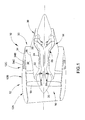
- FIGS. 2 through 6 represent various views of an assembly 40 through which a fan case and thrust reverser assembly of a gas turbine engine can be quickly coupled and decoupled to allow the thrust reverser assembly to translate aft and away from the fan case, for example, on one or more slider tracks (not shown).
- the assembly 40 represented in FIGS. 2 through 6 can be installed in a high-bypass gas turbine engine 10 of the type represented in FIG. 1 . While the assembly 40 can be adapted for installation at various locations of the engine 10, the assembly 40 is particularly intended to be installed between the fan cowl 12B and thrust reverser assembly 12C, for example, at a location of the nacelle 12 located axially between the high and low pressure compressor sections 22 and 24 of the engine 10.
- the assembly 40 is represented as including two ring-type components, a first of which will be referred to as the fan case 42 and the second will be referred to as a fixed structure 44 of a thrust reverser assembly.
- the fan case 42 is a static structure within the fan cowl 12B that surrounds the fan blades 18 of the engine 10
- the fixed structure 44 may include the cascade 34B and other static parts of the thrust reverser assembly 12C of the engine 10. Accordingly, it should be understood that the ring-type components shown in the figures and identified as the fan case 42 and fixed structure 44 are only portions of, respectively, a fan case and thrust reverser assembly typically found in a high-bypass gas turbine engine of the type represented in FIG. 1 .
- the component identified as the fan case 42 may be a portion of the entire structure that forms a fan case within the nacelle 12 of the engine 10, or a ring that is bolted or otherwise attached to a structure that together form a fan case of the engine 10.
- the component identified as the fixed structure 44 may be a portion of the entire structure that forms the fixed structure (including the cascade 34B) of the thrust reverser assembly 12C of the engine 10, or a ring that is bolted or otherwise attached to a structure that together form the fixed structure of the thrust reverser assembly 12C.
- the components will simply be referred to as the fan case 42 and fixed structure 44.
- the assembly 40 is represented in FIGS. 2 through 6 as comprising a clamping system adapted to couple and decouple the fan case 42 and the fixed structure 44 to allow the thrust reverser assembly 12C to translate aft and away from the fan case 42.
- the clamping system is configured to provide a method for coupling and decoupling the fan case 42 and thrust reverser assembly 12C by simultaneously engaging and disengaging flanges 48 and 50 associated with, respectively, the fan case 42 and the fixed structure 44 of the thrust reverser assembly 12C.
- the clamping system comprises a plurality of over-center clamping mechanisms 52, some of which are mounted to the fan case 42 and others to the fixed structure 44.
- the coupling and decoupling method provided by the clamping system entails the movement of each clamping mechanism 52 to simultaneously clamp portions of the flanges 48 and 50 together, as well as simultaneously release the flanges 48 and 50.
- the flange portions 48A and 50A preferably project in radially outward directions of the engine 10, so that the flange portions 48A and 50A lie in planes that are parallel to each other.
- the flanges 48 associated with the fan case 42 comprise multiple axially-offset flange portions 48A that extend around different circumferential portions of the nacelle 12.
- the flanges 50 associated with the fixed structure 44 comprise multiple axially-offset flange portions 50A that extend around different circumferential portions of the nacelle 12.
- the flange portions 48A of the fan case 42 and the flange portions 50A of the fixed structure 44 are complementarily axially offset and circumferentially located so that each flange portion 48A of the fan case 42 will mate with one of the flange portions 50A of the fixed structure 44.
- Each of the over-center clamping mechanisms 52 of the clamping system is also circumferentially and axially offset from each other, and dedicated to clamp one complementary pair of the flange portions 48A and 50A.
- each over-center clamping mechanism 52 is mounted to either the fixed structure 44 to clamp one of the flange portions 50A of the fixed structure 44 with one of the flange portions 48A of the fan case 42, or to the fan case 42 to clamp one of the flange portions 50A of the fixed structure 44 with one of the flange portions 48A of the fan case 42.
- Each of the over-center clamping mechanisms 52 of the clamping system comprises a clamping segment 54 that extends over a circumferential portion of the nacelle 12, a pivot link 56 at one circumferential end of the clamping segment 54, and an over-center link 58 at an oppositely-disposed circumferential end of the clamping segment 54. Because each clamping mechanism 52 is mounted to either the fan case 42 or the fixed structure 44, each pair of pivot and over-center links 56 and 58 for each mechanism 52 is pivotably mounted to either the fan case 42 or the fixed structure 44. As evident from FIGS. 2 , 3 and 4 , in the circumferential direction of the assembly 40, the mechanisms 52 alternate between being mounted to the fan case 42 or to the fixed structure 44.
- the circumferential ends of the mechanisms 52 overlap each other as a result of their pivot and over-center links 56 and 58 being axially aligned with one of the pivot or over-center links 56 and 58 of an adjacent mechanism 52.
- the over-center link 58 cooperates with the pivot link 56 to induce an over-center toggle operation in the clamping segment 54. Due to the pivoting movement of the pivot and over-center links 56 and 58, the movement of the clamping segment 54 comprises both a radially outward travel and then a radially inward travel combined with a circumferential travel between a position of the mechanism 52 that clamps a pair of flange portions 48A and 50A together and a position of the mechanism 52 that releases the pair of flange portions 48A and 50A. As should be evident from FIGS. 2 through 6 , an operator can readily cause each mechanism 52 to move between these two extremes by grasping a handle 60 that protrudes in a circumferential direction from the segment 54 adjacent the over-center link 58.
- the configurations of the over-center clamping mechanisms 52 are based on the design of a Marman clamp, which is a well-know device for connecting pipe joints.
- the present invention uses a plurality of axially and circumferentially offset mechanisms 52 to achieve a large-diameter connection between the fan case 42 and the fixed structure 44 of the thrust reverser assembly 12C.
- the multiple mechanisms 52 are not only convenient to operate, but also provide a level of redundancy, retaining a secure connection even in the event of a failure of one or more of the mechanisms 52.
- An optimal number of mechanisms 52 will vary depending on the given application, though the use of two to eight mechanisms 52 is believed to be practical for many applications.
- the invention may further comprise means (not shown) for locking the handles 60 to secure the mechanisms 52 in the clamping position, as well as additional tensioning devices similar to latches.
- the assembly 40 can further comprise a cutout 62 through which conduits 64 of any type can be routed through the assembly 40.
- a gas-tight seal (not shown) can be provided to minimize or prevent air flow losses through the assembly 40.
- FIG. 6 further shows a pair of shear pins 66 located on either side of the cutout 62 to reinforce the structural strength of the assembly 40 in the vicinity of the cutout 62.
Landscapes
- Engineering & Computer Science (AREA)
- Mechanical Engineering (AREA)
- General Engineering & Computer Science (AREA)
- Chemical & Material Sciences (AREA)
- Combustion & Propulsion (AREA)
- Structures Of Non-Positive Displacement Pumps (AREA)
Applications Claiming Priority (2)
| Application Number | Priority Date | Filing Date | Title |
|---|---|---|---|
| US201161493671P | 2011-06-06 | 2011-06-06 | |
| US13/325,203 US8479491B2 (en) | 2011-06-06 | 2011-12-14 | Clamping system and method for thrust reverser attachment |
Publications (2)
| Publication Number | Publication Date |
|---|---|
| EP2532872A2 true EP2532872A2 (de) | 2012-12-12 |
| EP2532872A3 EP2532872A3 (de) | 2018-04-25 |
Family
ID=46197167
Family Applications (1)
| Application Number | Title | Priority Date | Filing Date |
|---|---|---|---|
| EP12171077.6A Withdrawn EP2532872A3 (de) | 2011-06-06 | 2012-06-06 | Klemmsystem und Verfahren für Schubumkehrerbefestigung |
Country Status (4)
| Country | Link |
|---|---|
| US (1) | US8479491B2 (de) |
| EP (1) | EP2532872A3 (de) |
| JP (1) | JP5997508B2 (de) |
| CA (1) | CA2778592A1 (de) |
Families Citing this family (6)
| Publication number | Priority date | Publication date | Assignee | Title |
|---|---|---|---|---|
| US8727269B2 (en) * | 2011-06-06 | 2014-05-20 | General Electric Company | System and method for mounting an aircraft engine |
| EP3017170B1 (de) * | 2013-07-02 | 2021-06-23 | MRA Systems, LLC | Motor und bandklammer |
| US10309343B2 (en) * | 2014-11-06 | 2019-06-04 | Rohr, Inc. | Split sleeve hidden door thrust reverser |
| US9784214B2 (en) | 2014-11-06 | 2017-10-10 | Rohr, Inc. | Thrust reverser with hidden linkage blocker doors |
| US10655564B2 (en) | 2016-05-13 | 2020-05-19 | Rohr, Inc. | Thrust reverser system with hidden blocker doors |
| US9976696B2 (en) | 2016-06-21 | 2018-05-22 | Rohr, Inc. | Linear actuator with multi-degree of freedom mounting structure |
Family Cites Families (17)
| Publication number | Priority date | Publication date | Assignee | Title |
|---|---|---|---|---|
| JPS58126195U (ja) * | 1982-02-18 | 1983-08-27 | 東京精密測器株式会社 | フランジクランプ装置 |
| JPS61294206A (ja) * | 1985-06-19 | 1986-12-25 | 株式会社井上ジャパックス研究所 | パイプ等の接合方法 |
| JPH0734799Y2 (ja) * | 1988-08-16 | 1995-08-09 | 日産自動車株式会社 | フランジ締結用バンドの分離装置 |
| GB9407632D0 (en) * | 1994-04-18 | 1994-06-08 | Short Brothers Plc | An aircraft propulsive power unit |
| US5470114A (en) * | 1994-11-14 | 1995-11-28 | General Electric Company | Coupling assembly |
| US5875995A (en) * | 1997-05-20 | 1999-03-02 | Rohr, Inc. | Pivoting door type thrust reverser with deployable members for efflux control and flow separation |
| US6725542B1 (en) | 1999-09-17 | 2004-04-27 | Alan R Maguire | Method of assembling a gas turbine engine and nacelle |
| US7000952B2 (en) * | 2003-05-27 | 2006-02-21 | The Boeing Company | Duct separation restraint apparatus and method |
| US20050264010A1 (en) * | 2004-05-27 | 2005-12-01 | Wagner Wayne M | V-band clamp |
| DE102004050300B4 (de) * | 2004-10-15 | 2009-02-12 | Norma Germany Gmbh | Profilschelle |
| US7484356B1 (en) * | 2005-07-26 | 2009-02-03 | Aeronautical Concepts Of Exhaust, Llc | Cascade reverser without blocker doors |
| DK2160336T3 (da) * | 2007-06-13 | 2013-07-22 | Joinlock Pty Ltd | Forbindelsesmekanisme og fremgangsmåde |
| US20090102275A1 (en) * | 2007-10-22 | 2009-04-23 | General Electric Company | Wheel mounting assembly |
| FR2925120B1 (fr) * | 2007-12-18 | 2010-02-19 | Snecma | Extension de carter intermediaire pour turboreacteur d'aeronef, comprenant une rainure annulaire sectorisee de reception des capots de nacelle |
| US8181905B2 (en) | 2008-12-17 | 2012-05-22 | Rohr, Inc. | Aircraft engine nacelle with translating inlet cowl |
| US8398017B2 (en) * | 2009-02-04 | 2013-03-19 | Spirit Aerosystems, Inc. | Continuous composite fan duct and thrust reverser |
| FR2952615B1 (fr) * | 2009-11-18 | 2011-12-09 | Aircelle Sa | Ensemble de maintien de l'interface d'une structure externe fixe d'une nacelle et d'un carter de turboreacteur |
-
2011
- 2011-12-14 US US13/325,203 patent/US8479491B2/en active Active
-
2012
- 2012-06-01 CA CA2778592A patent/CA2778592A1/en not_active Abandoned
- 2012-06-04 JP JP2012126721A patent/JP5997508B2/ja not_active Expired - Fee Related
- 2012-06-06 EP EP12171077.6A patent/EP2532872A3/de not_active Withdrawn
Non-Patent Citations (1)
| Title |
|---|
| None |
Also Published As
| Publication number | Publication date |
|---|---|
| JP5997508B2 (ja) | 2016-09-28 |
| US8479491B2 (en) | 2013-07-09 |
| EP2532872A3 (de) | 2018-04-25 |
| JP2012251556A (ja) | 2012-12-20 |
| CA2778592A1 (en) | 2012-12-06 |
| US20120304621A1 (en) | 2012-12-06 |
Similar Documents
| Publication | Publication Date | Title |
|---|---|---|
| US8479491B2 (en) | Clamping system and method for thrust reverser attachment | |
| US8444084B2 (en) | Aeroengine mounting | |
| US8528857B2 (en) | Translatable jet engine thrust reverser configuration providing improved maintenance access | |
| US10655564B2 (en) | Thrust reverser system with hidden blocker doors | |
| US20080073460A1 (en) | Aeroengine mount | |
| US20070007388A1 (en) | Thrust reversers including locking assemblies for inhibiting deflection | |
| US10570853B2 (en) | Thrust reverser assembly | |
| US10851734B2 (en) | Thrust reverser assembly | |
| US9328735B2 (en) | Split ring valve | |
| EP3517766A1 (de) | Translationssperre für schwenktürschubumkehrvorrichtung | |
| CN111868369B (zh) | 旁路推进单元,包括具有可移动叶栅的推力反向器 | |
| US10759541B2 (en) | Nacelle bifurcation with leading edge structure | |
| CN115803258B (zh) | 包括可移除的和结构性的前部内部结构的用于具有很高涵道比的推进组件的机舱 | |
| EP4206456B1 (de) | Düse mit veränderlichem querschnitt und verfahren zum betrieb davon | |
| EP2969763B1 (de) | An einer gondel montiertes verriegelungssystem | |
| GB2384827A (en) | A Fastening Between The C-Duct and Core of a Ducted Fan Gas Turbine Engine. | |
| CN117642338A (zh) | 包括摆式分叉板的推进组件 | |
| US10670178B2 (en) | Slip joint assembly | |
| US11933247B2 (en) | Thrust reverser system latch assembly and method of operating same | |
| JP5782463B2 (ja) | 連接型スライダトラック | |
| CN117242253A (zh) | 包括连接到诸如出口导向轮叶的结构臂的致动器的飞行器推进组件 | |
| CN117222804A (zh) | 包括多功能固定结构的可移动叶栅推力反向器 | |
| US20190162134A1 (en) | Retention of a nozzle assembly for an engine |
Legal Events
| Date | Code | Title | Description |
|---|---|---|---|
| PUAI | Public reference made under article 153(3) epc to a published international application that has entered the european phase |
Free format text: ORIGINAL CODE: 0009012 |
|
| AK | Designated contracting states |
Kind code of ref document: A2 Designated state(s): AL AT BE BG CH CY CZ DE DK EE ES FI FR GB GR HR HU IE IS IT LI LT LU LV MC MK MT NL NO PL PT RO RS SE SI SK SM TR |
|
| AX | Request for extension of the european patent |
Extension state: BA ME |
|
| PUAL | Search report despatched |
Free format text: ORIGINAL CODE: 0009013 |
|
| AK | Designated contracting states |
Kind code of ref document: A3 Designated state(s): AL AT BE BG CH CY CZ DE DK EE ES FI FR GB GR HR HU IE IS IT LI LT LU LV MC MK MT NL NO PL PT RO RS SE SI SK SM TR |
|
| AX | Request for extension of the european patent |
Extension state: BA ME |
|
| RIC1 | Information provided on ipc code assigned before grant |
Ipc: F01D 25/24 20060101ALI20180322BHEP Ipc: F02K 1/64 20060101ALI20180322BHEP Ipc: F02K 1/56 20060101AFI20180322BHEP |
|
| STAA | Information on the status of an ep patent application or granted ep patent |
Free format text: STATUS: THE APPLICATION IS DEEMED TO BE WITHDRAWN |
|
| 18D | Application deemed to be withdrawn |
Effective date: 20181026 |