EP2532953B1 - Plaque prismatique - Google Patents
Plaque prismatique Download PDFInfo
- Publication number
- EP2532953B1 EP2532953B1 EP12169731.2A EP12169731A EP2532953B1 EP 2532953 B1 EP2532953 B1 EP 2532953B1 EP 12169731 A EP12169731 A EP 12169731A EP 2532953 B1 EP2532953 B1 EP 2532953B1
- Authority
- EP
- European Patent Office
- Prior art keywords
- cover
- light
- flank surfaces
- surface structure
- structure elements
- Prior art date
- Legal status (The legal status is an assumption and is not a legal conclusion. Google has not performed a legal analysis and makes no representation as to the accuracy of the status listed.)
- Active
Links
Images



Classifications
-
- F—MECHANICAL ENGINEERING; LIGHTING; HEATING; WEAPONS; BLASTING
- F21—LIGHTING
- F21V—FUNCTIONAL FEATURES OR DETAILS OF LIGHTING DEVICES OR SYSTEMS THEREOF; STRUCTURAL COMBINATIONS OF LIGHTING DEVICES WITH OTHER ARTICLES, NOT OTHERWISE PROVIDED FOR
- F21V5/00—Refractors for light sources
- F21V5/02—Refractors for light sources of prismatic shape
-
- F—MECHANICAL ENGINEERING; LIGHTING; HEATING; WEAPONS; BLASTING
- F21—LIGHTING
- F21Y—INDEXING SCHEME ASSOCIATED WITH SUBCLASSES F21K, F21L, F21S and F21V, RELATING TO THE FORM OR THE KIND OF THE LIGHT SOURCES OR OF THE COLOUR OF THE LIGHT EMITTED
- F21Y2103/00—Elongate light sources, e.g. fluorescent tubes
-
- F—MECHANICAL ENGINEERING; LIGHTING; HEATING; WEAPONS; BLASTING
- F21—LIGHTING
- F21Y—INDEXING SCHEME ASSOCIATED WITH SUBCLASSES F21K, F21L, F21S and F21V, RELATING TO THE FORM OR THE KIND OF THE LIGHT SOURCES OR OF THE COLOUR OF THE LIGHT EMITTED
- F21Y2105/00—Planar light sources
-
- F—MECHANICAL ENGINEERING; LIGHTING; HEATING; WEAPONS; BLASTING
- F21—LIGHTING
- F21Y—INDEXING SCHEME ASSOCIATED WITH SUBCLASSES F21K, F21L, F21S and F21V, RELATING TO THE FORM OR THE KIND OF THE LIGHT SOURCES OR OF THE COLOUR OF THE LIGHT EMITTED
- F21Y2105/00—Planar light sources
- F21Y2105/10—Planar light sources comprising a two-dimensional [2D] array of point-like light-generating elements
-
- F—MECHANICAL ENGINEERING; LIGHTING; HEATING; WEAPONS; BLASTING
- F21—LIGHTING
- F21Y—INDEXING SCHEME ASSOCIATED WITH SUBCLASSES F21K, F21L, F21S and F21V, RELATING TO THE FORM OR THE KIND OF THE LIGHT SOURCES OR OF THE COLOUR OF THE LIGHT EMITTED
- F21Y2115/00—Light-generating elements of semiconductor light sources
- F21Y2115/10—Light-emitting diodes [LED]
-
- F—MECHANICAL ENGINEERING; LIGHTING; HEATING; WEAPONS; BLASTING
- F21—LIGHTING
- F21Y—INDEXING SCHEME ASSOCIATED WITH SUBCLASSES F21K, F21L, F21S and F21V, RELATING TO THE FORM OR THE KIND OF THE LIGHT SOURCES OR OF THE COLOUR OF THE LIGHT EMITTED
- F21Y2115/00—Light-generating elements of semiconductor light sources
- F21Y2115/10—Light-emitting diodes [LED]
- F21Y2115/15—Organic light-emitting diodes [OLED]
-
- F—MECHANICAL ENGINEERING; LIGHTING; HEATING; WEAPONS; BLASTING
- F21—LIGHTING
- F21Y—INDEXING SCHEME ASSOCIATED WITH SUBCLASSES F21K, F21L, F21S and F21V, RELATING TO THE FORM OR THE KIND OF THE LIGHT SOURCES OR OF THE COLOUR OF THE LIGHT EMITTED
- F21Y2115/00—Light-generating elements of semiconductor light sources
- F21Y2115/20—Electroluminescent [EL] light sources
Definitions
- the present invention relates to a transparent cover.
- a transparent plate for coupling out light is known.
- the plate has on a surface three or four each offset by 60 ° or 45 ° sets of straight, parallel V-shaped grooves.
- This construction has the disadvantage that the light emerging from the plate has a small number of preferred directions, which are determined by the course and the cross section of the grooves.
- a refractive transparent plate which has conical recesses.
- the recesses each have the same size and their base circles touch each other, so that remain between the recesses flat surface areas.
- a translucent panel for a luminaire is known that is placed in front of a light source in the luminaire.
- the plate has a profiled surface, one side of the plate being provided with protrusions having a substantially conical surface.
- a base portion of each projection has a square shape and the surface of the base portion is tapered, but does not reach a vertex because it terminates at a circular edge. On the other side of the circular edge of the projection is concave.
- the DE 2 320 247 A1 further discloses a light-scattering plate for fluorescent tubes with conical refractive elements. Adjacent conical refractive elements may intersect in a section line, so that the flat surface of the Scattering plate between the base surfaces of the conical refractive elements are reduced.
- the DE 20 2010 002 744 U1 discloses a device for glare-reduced coupling out of light from a lamp having at least one structured surface on which at least one group of pyramid-shaped structural elements is arranged.
- the group comprises a structural element, the base surface of which is in the form of a hexagon, and two structural elements whose bases are in the form of triangles.
- a glass plate is known which has serpentine ribs which extend over an entire surface of the plate. The ribs are eccentric to each other and have apex lines which extend to substantially the same plane.
- a refractive lens element wherein a grid comprises a plurality of lenses which are connected to each other by a rib-shaped structure.
- the CN 101 886 763 A further discloses an LED area light source having a plurality of point light sources, first transparent prismatic lenses, and second transparent prismatic lenses and a substrate, wherein the point light sources are disposed on the substrate.
- a plurality of long, strip-shaped arc protrusions are formed on the light exit side of the first prismatic lenses and a plurality of long, striped V-shaped rib structures extend in at least two different directions on the light exit surface of the second prismatic lenses.
- an optical disc having a first surface, an opposite second surface, a plurality of depressions in the form of triangular prisms in the first surface and a plurality of elongated arcuate depressions in the second surface is known.
- the disclosed DE 10 2006 054 379 A1 a transparent plate having a surface structure, wherein the plate for forming the surface structure on at least one side more than two each offset by certain angles Flocks of straight, parallel, substantially V-shaped grooves.
- the invention provides a transparent cover, wherein the cover defines on at least a portion of a surface having a surface structure.
- the surface structure is formed from a plurality of regular, preferably identical, structural elements, wherein the structural elements each follow a baseline and have two, an angle enclosing flank surfaces.
- the baselines of the structural elements are parallel to the surface.
- the baselines of the structural elements also extend at least partially curved in a tangential plane to the surface and / or the surface structure has at least five base lines oriented in different directions.
- the cover can be designed in particular as a cover for a luminaire or for a luminous element.
- the cover according to the invention can be used, in particular, for one or more fluorescent lamps, LED (light emitting diode) or one or more planar light sources, e.g. OLED (organic light emitting diode) or electroluminescent light sources may be formed.
- the cover is used in particular to glare the lamp or the lamp.
- a line runs parallel to the surface if all points of the line are the same distance to the surface.
- the baselines can run in particular in the area.
- the surface can be particularly flat.
- the flank surfaces may be ascending or descending with respect to the surface.
- the structural element may in this case in particular comprise one or more projections and / or recesses.
- the present invention is based on the finding that light refraction takes place at the surface of the cover facing the light exit surface of the cover, the orientation of the surface regions determining a direction in which the light is refracted. Surface subareas whose surface normals deviate from the surface normal of the light exit surface reduce the glare effect of the exiting light.
- the present invention advantageously utilizes curved baselines or baselines oriented in at least five different spatial directions, thereby forming a plurality of surface subregions oriented in different spatial directions.
- a curved surface has an infinitely high number of surface normals pointing in different spatial directions.
- a curved baseline is oriented along its course in an infinite number of directions.
- the angle enclosed by the flank surfaces is understood to mean that angle which is enclosed in a cross section perpendicular to the base line by the chords of the flank surfaces passing through the sole and the apex of the flank surfaces at the apex.
- the refractive index of the cover can be in particular between 1 and 2, preferably between 1.1 and 1.8 and particularly preferably between 1.3 and 1.65. This results in an advantageous distribution of the exiting light, in which a glare effect is reduced.
- the surface structure is formed in at least one direction, preferably in two directions, by regularly repeating an always identical structural element, also referred to below as the basic structural element.
- the surface structure may be formed by repeating the basic structural element at regular intervals.
- the spacings may in each case be the same or different in the several directions.
- the periodic repetition may also include repetition at increasing or decreasing distances in one or more directions. This is particularly advantageous for non-planar light sources and / or curved covers.
- the structural elements in each case perpendicular to the base line on a constant along the baseline cross-section.
- This embodiment allows a simple production of the cover by milling the surface or a negative of the surface. Furthermore, this improves the homogeneity of the glare reduction.
- flank surfaces form an angle of between 45 ° and 150 °, in particular between 60 ° and 140 °, and preferably between 80 ° and 130 °. These angle values enable the surface structure to be produced by means of milling a tool with which the cover is produced by molding. Furthermore, such inclined flank surfaces contribute particularly to the glare of the lamp, since they break the exiting light to a main surface normal of the cover out.
- flank surfaces may include an angle of between 15 ° and 70 °, in particular between 20 ° and 60 °, and preferably between 25 ° and 50 ° with the surface of the cover.
- flank surfaces of the structural element may include an equal or different angle to the surface.
- a preferential direction is formed, for example, for a lamp with asymmetrical light distribution (for example for a light band device of a street lamp).
- the structural elements overlap one another.
- This construction makes it possible to have a multiplicity of differently oriented surface partial areas on a small surface area. This contributes in a particularly advantageous manner to glare. Furthermore, this makes it possible to fill the area with a small number of simply structured structural elements.
- the baselines of adjacent structural elements intersect.
- the stability of the plate becomes elevated.
- the tool with which the cover is made by molding can be made easier by milling, grinding and polishing.
- the combination of the baselines provides advantages for the molding process because the crosslinked baselines result in consistent air displacement paths, thereby reducing the risk of air entrapment during the molding process.
- the baseline is a closed line. This allows easy production of the cover. In addition, this allows a derivative of the static forces along the baseline.
- a structural element with a closed base line has a particularly high number of orientations of the surface subregions. In this case, it is particularly preferred that the base line is an ellipse line or a circular line. An ellipse line or a circular line covers in its course an orientation angle of 0 ° to 360 °. This contributes to improved glare reduction.
- adjacent structural elements with a circular baseline may have a distance from one another that is greater than or equal to the radius of the circular line and / or less than or equal to ⁇ 3 times the radius of the circular line.
- flank surfaces adjoin one another at the baseline.
- the formation of flat surface areas, which are oriented parallel to the light exit surface avoided. In this way, the dazzling effect is further increased.
- the base line forms a highest or lowest part of the surface structure with respect to the surface. This allows for easy production of the cover and allows optimal dissipation of static weight forces.
- flank surfaces of the structural elements in a cross-section perpendicular to the base line either convex or concave curved or straight.
- a curvature of the flank surfaces increases the number of orientations of the surface normal of the flank surfaces, whereby the light distribution can be influenced to a certain extent.
- the surface with the surface structure is curved or flat.
- the cover can extend as a whole flat or curved, in particular trough-shaped or dome-shaped curved. Curvature of the surface increases the number of orientations of the surface normal, thereby improving the glare, and allows side light emission (e.g., in a trough lamp).
- the cover may be formed in particular as a pan or as a plate. It can be provided in particular that the surface structure is formed on a surface of a film.
- the film can be applied to a transparent carrier element.
- the support member may be formed as a plate or tub.
- the film may have substantially the same refractive index as the carrier element.
- the film may be bonded to the support member, e.g. be glued.
- the adhesive may have substantially the same refractive index as the film and / or the carrier element. As a result, unwanted reflections are avoided.
- the carrier element is designed as a trough and the film is placed with the surface structure in the tub.
- the cover may further include a diffusion layer, e.g. have a diffusion film, which ensures a light scattering.
- the diffusion layer can be arranged in the light path in front of or behind the surface structure.
- the cover further comprises two or more elements, each provided with such a surface structure.
- the elements may in particular be films.
- the elements are in particular arranged one above the other. In this way, the anti-glare effect of the cover can be further increased.
- the elements can in particular be connected to one another.
- the surface structure is formed as a film. This allows the attachment of the surface structure on existing covers, which can be retrofitted in this way. Furthermore, it is avoided in this embodiment that the surface structure is heavily loaded statically.
- the surface structure has no areas parallel to the surface. This prevents light from escaping from the cover, which is not broken and deflected. In this embodiment, a larger portion of the cover surface contributes to glare.
- the baseline may also be partially straight in some embodiments.
- a straight course of a line here means a course which is not curved at any point in the tangential plane of the surface of the cover.
- a regular pattern of protrusions or depressions may be defined.
- This pattern may in particular have symmetries.
- the pattern may have one or more translational symmetries and / or rotational symmetries.
- the pattern may be described by a regular grid of grid points as well as an identical basic cell of pits and / or projections assigned to each grid point.
- the grating can have both a translation symmetry in at least two directions and an n-fold rotational symmetry.
- the basic cell can also have a number n of depressions or projections, wherein a basic cell here means a unit having a smallest number of depressions whose periodic repeating along the symmetry directions completely describe the pattern.
- the number of depressions or protrusions n in the base cell may be greater than the count n of the rotational symmetry of the grating. In this way, the formation of individual, accentuated preferred directions of the exiting light is avoided and achieved a homogeneous glare.
- the present invention provides a luminaire, in particular an interior or exterior luminaire, a tunnel luminaire, a street lamp, a surface-mounted luminaire, a recessed luminaire, a pendant luminaire, a wall lamp and / or a floor lamp with a cover of the type mentioned.
- the cover can be arranged between a light source of the luminaire and a light exit opening of the luminaire.
- the surface structure can be arranged in particular on one of the light exit surface of the lamp facing side of the cover.
- the luminaire can be designed such that light which leaves the luminaire through the light exit opening runs completely through the cover.
- the light exiting through the light exit opening can run completely through the surface structure of the cover.
- the luminaire has a regular arrangement of light sources, in particular LED, wherein the arrangement of the light sources is formed by a regular repetition of a cell from one or more light sources in the at least one direction.
- the pattern defined by the structural elements is repeated on the cover by the light sources.
- the arrangement of the light sources is optimized in such a way to the cover, that the glare effect of the cover is used optimally.
- the invention further provides a luminaire or only a luminous means with a cover as described above.
- the surface structure of the cover can provide a light control, for example, to de-fade the lamp.
- the surface structure may be arranged on the side facing the light source or on the side of the cover facing away from the light source.
- the surface structure e.g. as a foil, arranged on the side facing the bulb.
- Behind the light path behind a transparent support member of the cover may be arranged on the example, the film is applied flat.
- the surface of the structure opposite side of the cover can form the light exit surface of the luminaire and / or the bulb.
- the present invention provides a light source with a luminous element and a light path behind it arranged cover of the type described above.
- the cover can be arranged directly on or at a distance from the luminous element.
- the luminous body and the cover may be parallel to each other and spaced from each other. In particular, air can be between the luminous element and the cover.
- the luminous body and the cover may be connected to one another, in particular glued together.
- the refractive index of the adhesive may in particular be between 1.1 and 1.8 and preferably between 1.3 and 1.65.
- the adhesive may alternatively or additionally have substantially the same refractive index as the cover. In this way, unwanted reflections are avoided.
- a light guide such as a hollow light guide.
- the luminous element may in particular be of a planar design, e.g. as a planar OLED.
- a luminous surface of the luminous element can in particular run parallel to the cover.
- the cover may in particular extend over an entire luminous surface of the luminous element.
- FIG. 1 For example, a structural element 1 of the present invention is shown from above.
- the structural elements and their arrangement in the FIGS. 1 . 2 and 3 refer to the same embodiment.
- the structural element 1 consists of a base line 2 and two along these adjacent flank surfaces 4, 5.
- the base line 2 is circular.
- In the interior of the structural element 1 is a planar portion 6.
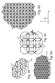
- FIG. 1b a surface structure of nine such structural elements 1 is shown.
- the structural elements 1 are arranged side by side in a row, with adjacent structural elements 1 overlap. Adjacent structural elements 1 are each offset by a distance which corresponds to the radius of the base line 2 of the structural elements 1.
- a multiplicity of depressions are formed between the base lines 2, which are designated generally by the reference numeral 3.
- Figure 1c is a surface texture with two of the in FIG. 1b illustrated rows of structural elements 1 shown. The two rows are arranged offset parallel to each other about the radius of the base line 2.
- Figure 1d shows a surface structure consisting of a plurality of structural elements 1.
- the structural elements 1 correspond to the in FIG. 1a This serves as a basic structural element, which is repeated along two directions a, b in each case at a uniform distance. there overlap adjacent structural elements 1 each other, so that overlap their baselines 2. In this way, a plurality of recesses 3 of the surface structure is formed.
- the directions a, b include an angle of 60 °.
- FIG. 2 shows a perspective view of a surface structure consisting of structural elements 1.
- the structural element 1 corresponds to that of Figure 1a-d and comprises a circular base line 2 and two flank surfaces 4, 5.
- the structural elements 1 overlap one another so that their base lines 2 overlap.
- the structural element 1 is formed as a circle following projection. In this way, a plurality of depressions 3 are formed between the base lines 2 of the structural elements 1.
- the baselines 2 are connected to each other. They form a network on the surface.
- FIGS. 3a to 3d show in various sections a cover 10, which has a plurality of structural elements 1.
- the structural elements 1 each comprise a circular baseline 2.
- FIG. 3a and b show a perspective view of different sections of the cover 10th
- Figure 3c and 3d show sections of the surface structure of the cover 10 from above.
- Figure 3c In particular, the construction of the surface structure by means of the baseline 2 is shown. In this case, six base lines touch each other at a point 400.
- Two different types of depressions are formed in the surface structure: a depression 31, which is delimited by two arc-shaped sections of the base line 2 and depressions 32, which are delimited by three arc-shaped sections of the base line 2 becomes.
- a depression 31 adjoins two depressions 32, while a depression 32 adjoins three depressions 31.
- FIGS. 4a to d show a further cover 20 according to another embodiment of the present invention.
- the cover has a surface structure which is constructed from a structural element 1.
- the structural element 1 corresponds to the in FIG. 1a shown structural element, which is designed as a circular projection.
- the surface structure is formed by a regular repetition of the structural element 1 in two directions c, d, which also enclose an angle of 60 °.
- the structural elements 1 are arranged at a greater distance. In the process, neighboring ones overlap Structural elements 1, so that overlap their baselines 2. In this way, depressions 3 are defined in the surface structure.
- FIGS. 5a to 5d shows a cover 30 according to another embodiment of the present invention.
- This has a surface structure which is formed by circular-shaped structural elements 1, as in FIG. 1a shown.
- the structural element 1 is a circular projection on the surface of the cover.
- the structural element 1 is repeated in two directions e, f at equal intervals.
- the distances in which the structural element 1 is repeated along the directions e, f is the same for both directions e, f. Compared to the in FIG. 4 shown embodiment, the distance is greater.
- FIGS. 6a to 6d show a cover 40 according to another embodiment of the present invention.
- This has a surface structure which has the same structural element 1 as the embodiments described above.
- the structural element 1, which comprises a circular baseline 2 is thereby repeated along two directions g, h at uniform intervals.
- the directions g, h enclose an angle of 90 °.
- the structural element 1 is thereby repeated along the directions g, h at equal intervals.
- the spacing of adjacent structural elements 1 in this case amounts to ⁇ 2 times the radius of the circular baseline 2 in both directions g, h.
- Figure 7a shows a surface structure of a cover.
- the surface structure is formed from a structural element with a straight base line 9, which is followed by flank surfaces 6 on both sides.
- surface structure has six different structural elements, which are each repeated at a distance.
- various structural elements are understood to mean that a basic structural element is oriented in different directions in order to define a structural element for each orientation angle.
- the individual structural elements differ in the orientation of the baseline 9.
- the baselines 9 of the structural elements form an angle to one another, which is an integer multiple of 30 °. In this way, a plurality of recesses 3 of the surface structure is formed.
- FIG. 7b shows a surface structure of a cover.
- the surface structure is formed by eight different structural elements.
- Each structural element comprises a straight base line 9.
- the base lines 9 of the various structural elements enclose an angle which is an integer multiple of 22.5 °.
- FIGS. 8a to 8c For example, cross-sections of various structural elements of the present invention are shown.
- the cross sections are perpendicular to the baseline 2.
- the flank surfaces 4, 5 of the structural element run straight in the cross section and adjoin one another at a point of the base line 2.
- the flank surfaces include an angle ⁇ .
- FIG. 8b shows a cross section in which the flank surfaces each extend convex.
- the flank surfaces include an angle ⁇ .
- FIG. 8c shows a cross section with convex flank surfaces. For non-flat flank surfaces, the angle ⁇ as the intersection angle of the two chords of the flank surfaces (in the Figures 8b and 8c defined as dashed lines).
- FIG. 8d shows a cross section through a structural element, which in addition to the lateral flank surfaces 41, 42 has a plateau section 43.
- the flank surfaces 41, 42 close to each other an angle ⁇ . Between the flank surfaces 41, 42 is the plateau section 43.
- FIG. 8e shows a cross section through another structural element according to the present invention.
- the structural element has two flank surfaces 41 ', 42', which enclose an angle ⁇ . In this case, however, the flank surfaces 41 ', 42' have different angles to a surface normal 44 of the surface of the cover.
- the structural elements may be formed as recesses.
- in particular circular recesses are possible, which may be arranged as in the embodiments described above.
- the in FIG. 8 shown cross sections may be inverted in some embodiments.
Landscapes
- Engineering & Computer Science (AREA)
- General Engineering & Computer Science (AREA)
- Non-Portable Lighting Devices Or Systems Thereof (AREA)
Claims (13)
- Couvercle (10 ; 20 ; 30 ; 40) transparent, le couvercle (10 ; 20 ; 30 ; 40) définissant sur au moins une zone partielle une surface avec une structure superficielle, ladite structure superficielle étant constituée de plusieurs éléments structurels (1), lesdits éléments structurels (1) suivant chacune une ligne de base (2) et comportant deux surfaces de flanc (4, 5) formant un angle (α) entre elles,
les lignes de base (2) des éléments structurels (1) étant parallèles à la surface, les surfaces de flanc (4, 5) s'étendant en pente ascendante ou descendante par rapport à la surface, et les lignes de base (2) des éléments structurels (1) étant courbées au moins partiellement dans un plan tangentiel à la surface,
caractérisé en ce que des éléments structurels (1) adjacents se chevauchent de telle sorte que leurs lignes de base (2) se recoupent. - Couvercle (10 ; 20 ; 30 ; 40) selon la revendication 1, dans lequel la structure superficielle est formée par une répétition régulière d'un élément structurel (1) toujours identique dans au moins une direction, de préférence dans deux directions.
- Couvercle (10 ; 20 ; 30 ; 40) selon l'une quelconque des revendications précédentes, dans lequel les éléments structurels (1) présentent une section transversale constante dans les plans de coupe perpendiculairement à leur ligne de base (2), dans la mesure où les éléments structurels ne se superposent pas aux éléments structurels (1) adjacents.
- Couvercle (10 ; 20 ; 30 ; 40) selon l'une quelconque des revendications précédentes, dans lequel les surfaces de flanc (4, 5) forment entre elles un angle (α) entre 45° et 150°, en particulier entre 60° et 140°, et de préférence entre 80° et 130°.
- Couvercle (10 ; 20 ; 30 ; 40) selon l'une quelconque des revendications précédentes, dans lequel les surfaces de flanc (4, 5) se jouxtent au niveau de la ligne de base (2).
- Couvercle (10 ; 20 ; 30 ; 40) selon l'une quelconque des revendications précédentes, dans lequel la ligne de base (2) forme une partie de la structure superficielle, laquelle est située plus haut ou plus bas que la surface.
- Couvercle (10 ; 20 ; 30 ; 40) selon l'une quelconque des revendications précédentes, dans lequel les surfaces de flanc (4, 5) des éléments structurels (1) s'étendent avec une courbure convexe ou concave ou de manière rectiligne sur une coupe transversale perpendiculaire à la ligne de base (2).
- Couvercle (10 ; 20 ; 30 ; 40) selon l'une quelconque des revendications précédentes, dans lequel la surface avec la structure superficielle est bombée ou plane.
- Couvercle (10 ; 20 ; 30 ; 40) selon l'une quelconque des revendications précédentes, dans lequel la structure superficielle est réalisée dans une surface d'un film.
- Couvercle (10 ; 20 ; 30 ; 40) selon l'une quelconque des revendications précédentes, dans lequel la structure superficielle ne comporte pas de zones parallèles à la surface.
- Luminaire comportant un couvercle (10 ; 20 ; 30 ; 40) selon l'une des revendications précédentes.
- Luminaire selon la revendication 11, avec référence à la revendication 2, le luminaire comportant, en outre, un système régulier de sources lumineuses, en particulier des diodes électroluminescentes, ledit système de sources lumineuses étant formé par une répétition régulière d'une cellule, constituée d'une ou de plusieurs sources lumineuses, le long d'au moins une direction.
- Moyen d'éclairage, qui comporte un corps d'éclairage et un couvercle selon l'une des revendications 1 à 10, disposé en aval dudit corps d'éclairage dans la trajectoire de la lumière.
Applications Claiming Priority (1)
| Application Number | Priority Date | Filing Date | Title |
|---|---|---|---|
| DE102011103981A DE102011103981A1 (de) | 2011-06-10 | 2011-06-10 | Prismenplatte |
Publications (2)
| Publication Number | Publication Date |
|---|---|
| EP2532953A1 EP2532953A1 (fr) | 2012-12-12 |
| EP2532953B1 true EP2532953B1 (fr) | 2015-07-08 |
Family
ID=46172707
Family Applications (1)
| Application Number | Title | Priority Date | Filing Date |
|---|---|---|---|
| EP12169731.2A Active EP2532953B1 (fr) | 2011-06-10 | 2012-05-29 | Plaque prismatique |
Country Status (2)
| Country | Link |
|---|---|
| EP (1) | EP2532953B1 (fr) |
| DE (1) | DE102011103981A1 (fr) |
Families Citing this family (1)
| Publication number | Priority date | Publication date | Assignee | Title |
|---|---|---|---|---|
| DE102016215605A1 (de) | 2016-08-19 | 2018-02-22 | Osram Gmbh | Entblendungsplatte und Verfahren zum Herstellen einer Entblendungsplatte |
Family Cites Families (9)
| Publication number | Priority date | Publication date | Assignee | Title |
|---|---|---|---|---|
| US720138A (en) * | 1900-10-18 | 1903-02-10 | Edward Walsh Jr | Curvilinear prismatic glass. |
| GB878215A (en) | 1956-12-10 | 1961-09-27 | Holophane Ltd | Light refracting and transmitting plates and equipment using the same |
| US3794829A (en) * | 1972-04-20 | 1974-02-26 | I Taltavull | Non-luminance lighting panel |
| US4703405A (en) * | 1986-07-17 | 1987-10-27 | Ian Lewin | Glare reducing lens |
| WO2005083317A1 (fr) * | 2004-02-20 | 2005-09-09 | Koninklijke Philips Electronics N.V. | Panneau lumineux translucide, luminaire et procede de fabrication d'un panneau |
| DE102006054379A1 (de) * | 2006-11-17 | 2008-05-21 | Zumtobel Lighting Gmbh | Transparente Platte mit einer Oberflächenstruktur zum weitgehend blendfreiem Auskoppeln des von einer Leuchte erzeugten Lichts |
| US8016446B2 (en) * | 2008-07-04 | 2011-09-13 | Hon Hai Precision Industry Co., Ltd. | Optical plate and backlight module using the same |
| DE202010002744U1 (de) * | 2010-02-24 | 2010-07-08 | Bwf Kunststoffe Gmbh & Co. Kg | Vorrichtung zum blendreduzierten Auskoppeln von Licht |
| CN101886763B (zh) * | 2010-07-26 | 2012-07-18 | 鸿富锦精密工业(深圳)有限公司 | Led面光源装置 |
-
2011
- 2011-06-10 DE DE102011103981A patent/DE102011103981A1/de not_active Ceased
-
2012
- 2012-05-29 EP EP12169731.2A patent/EP2532953B1/fr active Active
Also Published As
| Publication number | Publication date |
|---|---|
| EP2532953A1 (fr) | 2012-12-12 |
| DE102011103981A1 (de) | 2012-12-13 |
Similar Documents
| Publication | Publication Date | Title |
|---|---|---|
| EP2556292B1 (fr) | Système d'éclairage à plaque optique | |
| EP2058581B1 (fr) | Lampe DEL destinée à la conception de la distribution de la puissance d'éclairage | |
| DE102015220323B4 (de) | Lichtleiterplatte und flächige Lichtquellenvorrichtung | |
| DE102004026530B3 (de) | Optikkörper | |
| DE102006053537A1 (de) | Lichtverteiler für Fahrzeugbeleuchtungsmodule | |
| EP3655289B1 (fr) | Composant pour véhicule | |
| EP3408584B1 (fr) | Appareil d'éclairage muni d'un élément de recouvrement pyramidal ou conique | |
| DE202013012202U1 (de) | Optisches Element mit einem TIR-Flächenabschnitt für verbesserte räumliche Lichtverteilung | |
| EP2647904B1 (fr) | Plaque prismatique dotée d'angles de flanc variables | |
| EP2532953B1 (fr) | Plaque prismatique | |
| EP3527880A1 (fr) | Luminaire | |
| EP3023689A1 (fr) | Dispositif d'éclairage | |
| DE19957584A1 (de) | Leuchte | |
| DE102013211311A1 (de) | Flächenlichtquelle | |
| WO2011124294A1 (fr) | Dispositif pour le découplage réduit au niveau de l'éblouissement de la lumière | |
| DE202013103401U1 (de) | Freiformoptik für LED-Straßenleuchten | |
| EP2924343B1 (fr) | Lampe à del dotée d'une optique réfractive destinée au mélange de la lumière | |
| EP1156268B1 (fr) | Lampe à guide de lumière avec structure réfractive non uniforme | |
| EP1209409B1 (fr) | Dispositif d'éclairage extérieur à caratéristiques d' émission de lumière ameliorées | |
| AT528405B1 (de) | Verfahren zur Herstellung eines Lichtlenkobjektes, insbesondere einer Lichtlenkfolie, und damit hergestelltes Lichtlenkobjekt | |
| DE10011516A1 (de) | Leuchtensystem | |
| EP2647905B1 (fr) | Plaque prismatique dotée d'angles de flanc variables | |
| DE102014104339B4 (de) | Zentrales Aufhellungselement für LED-Leuchten | |
| EP1900998B1 (fr) | Réflecteur doté d'une structure émettant de la lumière | |
| DE102006030646A1 (de) | Innenraumleuchte zur Ausleuchtung einer Wand oder Decke |
Legal Events
| Date | Code | Title | Description |
|---|---|---|---|
| PUAI | Public reference made under article 153(3) epc to a published international application that has entered the european phase |
Free format text: ORIGINAL CODE: 0009012 |
|
| AK | Designated contracting states |
Kind code of ref document: A1 Designated state(s): AL AT BE BG CH CY CZ DE DK EE ES FI FR GB GR HR HU IE IS IT LI LT LU LV MC MK MT NL NO PL PT RO RS SE SI SK SM TR |
|
| AX | Request for extension of the european patent |
Extension state: BA ME |
|
| 17P | Request for examination filed |
Effective date: 20130606 |
|
| RBV | Designated contracting states (corrected) |
Designated state(s): AL AT BE BG CH CY CZ DE DK EE ES FI FR GB GR HR HU IE IS IT LI LT LU LV MC MK MT NL NO PL PT RO RS SE SI SK SM TR |
|
| 17Q | First examination report despatched |
Effective date: 20131209 |
|
| GRAP | Despatch of communication of intention to grant a patent |
Free format text: ORIGINAL CODE: EPIDOSNIGR1 |
|
| INTG | Intention to grant announced |
Effective date: 20150225 |
|
| RIC1 | Information provided on ipc code assigned before grant |
Ipc: F21Y 101/02 20060101ALN20150213BHEP Ipc: F21V 5/00 20150101AFI20150213BHEP Ipc: F21V 5/02 20060101ALI20150213BHEP |
|
| GRAS | Grant fee paid |
Free format text: ORIGINAL CODE: EPIDOSNIGR3 |
|
| GRAA | (expected) grant |
Free format text: ORIGINAL CODE: 0009210 |
|
| AK | Designated contracting states |
Kind code of ref document: B1 Designated state(s): AL AT BE BG CH CY CZ DE DK EE ES FI FR GB GR HR HU IE IS IT LI LT LU LV MC MK MT NL NO PL PT RO RS SE SI SK SM TR |
|
| REG | Reference to a national code |
Ref country code: GB Ref legal event code: FG4D Free format text: NOT ENGLISH |
|
| REG | Reference to a national code |
Ref country code: AT Ref legal event code: REF Ref document number: 735695 Country of ref document: AT Kind code of ref document: T Effective date: 20150715 Ref country code: CH Ref legal event code: NV Representative=s name: ISLER AND PEDRAZZINI AG, CH Ref country code: CH Ref legal event code: EP |
|
| REG | Reference to a national code |
Ref country code: IE Ref legal event code: FG4D Free format text: LANGUAGE OF EP DOCUMENT: GERMAN |
|
| REG | Reference to a national code |
Ref country code: DE Ref legal event code: R096 Ref document number: 502012003672 Country of ref document: DE |
|
| REG | Reference to a national code |
Ref country code: NL Ref legal event code: MP Effective date: 20150708 |
|
| REG | Reference to a national code |
Ref country code: LT Ref legal event code: MG4D |
|
| PG25 | Lapsed in a contracting state [announced via postgrant information from national office to epo] |
Ref country code: GR Free format text: LAPSE BECAUSE OF FAILURE TO SUBMIT A TRANSLATION OF THE DESCRIPTION OR TO PAY THE FEE WITHIN THE PRESCRIBED TIME-LIMIT Effective date: 20151009 Ref country code: FI Free format text: LAPSE BECAUSE OF FAILURE TO SUBMIT A TRANSLATION OF THE DESCRIPTION OR TO PAY THE FEE WITHIN THE PRESCRIBED TIME-LIMIT Effective date: 20150708 Ref country code: NO Free format text: LAPSE BECAUSE OF FAILURE TO SUBMIT A TRANSLATION OF THE DESCRIPTION OR TO PAY THE FEE WITHIN THE PRESCRIBED TIME-LIMIT Effective date: 20151008 Ref country code: LV Free format text: LAPSE BECAUSE OF FAILURE TO SUBMIT A TRANSLATION OF THE DESCRIPTION OR TO PAY THE FEE WITHIN THE PRESCRIBED TIME-LIMIT Effective date: 20150708 Ref country code: LT Free format text: LAPSE BECAUSE OF FAILURE TO SUBMIT A TRANSLATION OF THE DESCRIPTION OR TO PAY THE FEE WITHIN THE PRESCRIBED TIME-LIMIT Effective date: 20150708 |
|
| PG25 | Lapsed in a contracting state [announced via postgrant information from national office to epo] |
Ref country code: SE Free format text: LAPSE BECAUSE OF FAILURE TO SUBMIT A TRANSLATION OF THE DESCRIPTION OR TO PAY THE FEE WITHIN THE PRESCRIBED TIME-LIMIT Effective date: 20150708 Ref country code: RS Free format text: LAPSE BECAUSE OF FAILURE TO SUBMIT A TRANSLATION OF THE DESCRIPTION OR TO PAY THE FEE WITHIN THE PRESCRIBED TIME-LIMIT Effective date: 20150708 Ref country code: PL Free format text: LAPSE BECAUSE OF FAILURE TO SUBMIT A TRANSLATION OF THE DESCRIPTION OR TO PAY THE FEE WITHIN THE PRESCRIBED TIME-LIMIT Effective date: 20150708 Ref country code: HR Free format text: LAPSE BECAUSE OF FAILURE TO SUBMIT A TRANSLATION OF THE DESCRIPTION OR TO PAY THE FEE WITHIN THE PRESCRIBED TIME-LIMIT Effective date: 20150708 Ref country code: IS Free format text: LAPSE BECAUSE OF FAILURE TO SUBMIT A TRANSLATION OF THE DESCRIPTION OR TO PAY THE FEE WITHIN THE PRESCRIBED TIME-LIMIT Effective date: 20151108 Ref country code: PT Free format text: LAPSE BECAUSE OF FAILURE TO SUBMIT A TRANSLATION OF THE DESCRIPTION OR TO PAY THE FEE WITHIN THE PRESCRIBED TIME-LIMIT Effective date: 20151109 Ref country code: ES Free format text: LAPSE BECAUSE OF FAILURE TO SUBMIT A TRANSLATION OF THE DESCRIPTION OR TO PAY THE FEE WITHIN THE PRESCRIBED TIME-LIMIT Effective date: 20150708 |
|
| REG | Reference to a national code |
Ref country code: DE Ref legal event code: R097 Ref document number: 502012003672 Country of ref document: DE |
|
| PG25 | Lapsed in a contracting state [announced via postgrant information from national office to epo] |
Ref country code: EE Free format text: LAPSE BECAUSE OF FAILURE TO SUBMIT A TRANSLATION OF THE DESCRIPTION OR TO PAY THE FEE WITHIN THE PRESCRIBED TIME-LIMIT Effective date: 20150708 Ref country code: DK Free format text: LAPSE BECAUSE OF FAILURE TO SUBMIT A TRANSLATION OF THE DESCRIPTION OR TO PAY THE FEE WITHIN THE PRESCRIBED TIME-LIMIT Effective date: 20150708 Ref country code: SK Free format text: LAPSE BECAUSE OF FAILURE TO SUBMIT A TRANSLATION OF THE DESCRIPTION OR TO PAY THE FEE WITHIN THE PRESCRIBED TIME-LIMIT Effective date: 20150708 Ref country code: CZ Free format text: LAPSE BECAUSE OF FAILURE TO SUBMIT A TRANSLATION OF THE DESCRIPTION OR TO PAY THE FEE WITHIN THE PRESCRIBED TIME-LIMIT Effective date: 20150708 |
|
| PLBE | No opposition filed within time limit |
Free format text: ORIGINAL CODE: 0009261 |
|
| STAA | Information on the status of an ep patent application or granted ep patent |
Free format text: STATUS: NO OPPOSITION FILED WITHIN TIME LIMIT |
|
| REG | Reference to a national code |
Ref country code: FR Ref legal event code: PLFP Year of fee payment: 5 |
|
| PG25 | Lapsed in a contracting state [announced via postgrant information from national office to epo] |
Ref country code: RO Free format text: LAPSE BECAUSE OF FAILURE TO SUBMIT A TRANSLATION OF THE DESCRIPTION OR TO PAY THE FEE WITHIN THE PRESCRIBED TIME-LIMIT Effective date: 20150708 |
|
| 26N | No opposition filed |
Effective date: 20160411 |
|
| PG25 | Lapsed in a contracting state [announced via postgrant information from national office to epo] |
Ref country code: BE Free format text: LAPSE BECAUSE OF NON-PAYMENT OF DUE FEES Effective date: 20160531 Ref country code: SI Free format text: LAPSE BECAUSE OF FAILURE TO SUBMIT A TRANSLATION OF THE DESCRIPTION OR TO PAY THE FEE WITHIN THE PRESCRIBED TIME-LIMIT Effective date: 20150708 |
|
| PG25 | Lapsed in a contracting state [announced via postgrant information from national office to epo] |
Ref country code: LU Free format text: LAPSE BECAUSE OF FAILURE TO SUBMIT A TRANSLATION OF THE DESCRIPTION OR TO PAY THE FEE WITHIN THE PRESCRIBED TIME-LIMIT Effective date: 20160529 |
|
| REG | Reference to a national code |
Ref country code: IE Ref legal event code: MM4A |
|
| REG | Reference to a national code |
Ref country code: FR Ref legal event code: PLFP Year of fee payment: 6 |
|
| PG25 | Lapsed in a contracting state [announced via postgrant information from national office to epo] |
Ref country code: IE Free format text: LAPSE BECAUSE OF NON-PAYMENT OF DUE FEES Effective date: 20160529 |
|
| PG25 | Lapsed in a contracting state [announced via postgrant information from national office to epo] |
Ref country code: NL Free format text: LAPSE BECAUSE OF FAILURE TO SUBMIT A TRANSLATION OF THE DESCRIPTION OR TO PAY THE FEE WITHIN THE PRESCRIBED TIME-LIMIT Effective date: 20150708 |
|
| PGFP | Annual fee paid to national office [announced via postgrant information from national office to epo] |
Ref country code: GB Payment date: 20170519 Year of fee payment: 6 |
|
| PGFP | Annual fee paid to national office [announced via postgrant information from national office to epo] |
Ref country code: IT Payment date: 20170526 Year of fee payment: 6 |
|
| REG | Reference to a national code |
Ref country code: FR Ref legal event code: PLFP Year of fee payment: 7 |
|
| PG25 | Lapsed in a contracting state [announced via postgrant information from national office to epo] |
Ref country code: SM Free format text: LAPSE BECAUSE OF FAILURE TO SUBMIT A TRANSLATION OF THE DESCRIPTION OR TO PAY THE FEE WITHIN THE PRESCRIBED TIME-LIMIT Effective date: 20150708 Ref country code: HU Free format text: LAPSE BECAUSE OF FAILURE TO SUBMIT A TRANSLATION OF THE DESCRIPTION OR TO PAY THE FEE WITHIN THE PRESCRIBED TIME-LIMIT; INVALID AB INITIO Effective date: 20120529 Ref country code: CY Free format text: LAPSE BECAUSE OF FAILURE TO SUBMIT A TRANSLATION OF THE DESCRIPTION OR TO PAY THE FEE WITHIN THE PRESCRIBED TIME-LIMIT Effective date: 20150708 |
|
| PG25 | Lapsed in a contracting state [announced via postgrant information from national office to epo] |
Ref country code: TR Free format text: LAPSE BECAUSE OF FAILURE TO SUBMIT A TRANSLATION OF THE DESCRIPTION OR TO PAY THE FEE WITHIN THE PRESCRIBED TIME-LIMIT Effective date: 20150708 Ref country code: MC Free format text: LAPSE BECAUSE OF FAILURE TO SUBMIT A TRANSLATION OF THE DESCRIPTION OR TO PAY THE FEE WITHIN THE PRESCRIBED TIME-LIMIT Effective date: 20150708 Ref country code: MT Free format text: LAPSE BECAUSE OF FAILURE TO SUBMIT A TRANSLATION OF THE DESCRIPTION OR TO PAY THE FEE WITHIN THE PRESCRIBED TIME-LIMIT Effective date: 20150708 Ref country code: MK Free format text: LAPSE BECAUSE OF FAILURE TO SUBMIT A TRANSLATION OF THE DESCRIPTION OR TO PAY THE FEE WITHIN THE PRESCRIBED TIME-LIMIT Effective date: 20150708 |
|
| PG25 | Lapsed in a contracting state [announced via postgrant information from national office to epo] |
Ref country code: BG Free format text: LAPSE BECAUSE OF FAILURE TO SUBMIT A TRANSLATION OF THE DESCRIPTION OR TO PAY THE FEE WITHIN THE PRESCRIBED TIME-LIMIT Effective date: 20150708 |
|
| PGFP | Annual fee paid to national office [announced via postgrant information from national office to epo] |
Ref country code: CH Payment date: 20180523 Year of fee payment: 7 |
|
| PG25 | Lapsed in a contracting state [announced via postgrant information from national office to epo] |
Ref country code: AL Free format text: LAPSE BECAUSE OF FAILURE TO SUBMIT A TRANSLATION OF THE DESCRIPTION OR TO PAY THE FEE WITHIN THE PRESCRIBED TIME-LIMIT Effective date: 20150708 |
|
| GBPC | Gb: european patent ceased through non-payment of renewal fee |
Effective date: 20180529 |
|
| REG | Reference to a national code |
Ref country code: CH Ref legal event code: PK Free format text: BERICHTIGUNGEN |
|
| RIC2 | Information provided on ipc code assigned after grant |
Ipc: F21V 5/00 20180101AFI20150213BHEP Ipc: F21Y 101/02 20000101ALN20150213BHEP Ipc: F21V 5/02 20060101ALI20150213BHEP |
|
| PG25 | Lapsed in a contracting state [announced via postgrant information from national office to epo] |
Ref country code: IT Free format text: LAPSE BECAUSE OF NON-PAYMENT OF DUE FEES Effective date: 20180529 Ref country code: GB Free format text: LAPSE BECAUSE OF NON-PAYMENT OF DUE FEES Effective date: 20180529 |
|
| REG | Reference to a national code |
Ref country code: CH Ref legal event code: PL |
|
| PG25 | Lapsed in a contracting state [announced via postgrant information from national office to epo] |
Ref country code: CH Free format text: LAPSE BECAUSE OF NON-PAYMENT OF DUE FEES Effective date: 20190531 Ref country code: LI Free format text: LAPSE BECAUSE OF NON-PAYMENT OF DUE FEES Effective date: 20190531 |
|
| REG | Reference to a national code |
Ref country code: DE Ref legal event code: R082 Ref document number: 502012003672 Country of ref document: DE Representative=s name: BOEHMERT & BOEHMERT ANWALTSPARTNERSCHAFT MBB -, DE Ref country code: DE Ref legal event code: R081 Ref document number: 502012003672 Country of ref document: DE Owner name: SITECO GMBH, DE Free format text: FORMER OWNER: SITECO BELEUCHTUNGSTECHNIK GMBH, 83301 TRAUNREUT, DE |
|
| REG | Reference to a national code |
Ref country code: AT Ref legal event code: PC Ref document number: 735695 Country of ref document: AT Kind code of ref document: T Owner name: SITECO GMBH, DE Effective date: 20210629 |
|
| PGFP | Annual fee paid to national office [announced via postgrant information from national office to epo] |
Ref country code: DE Payment date: 20250519 Year of fee payment: 14 |
|
| PGFP | Annual fee paid to national office [announced via postgrant information from national office to epo] |
Ref country code: FR Payment date: 20250526 Year of fee payment: 14 |
|
| PGFP | Annual fee paid to national office [announced via postgrant information from national office to epo] |
Ref country code: AT Payment date: 20250519 Year of fee payment: 14 |