EP3527880A1 - Luminaire - Google Patents
Luminaire Download PDFInfo
- Publication number
- EP3527880A1 EP3527880A1 EP19156893.0A EP19156893A EP3527880A1 EP 3527880 A1 EP3527880 A1 EP 3527880A1 EP 19156893 A EP19156893 A EP 19156893A EP 3527880 A1 EP3527880 A1 EP 3527880A1
- Authority
- EP
- European Patent Office
- Prior art keywords
- lens
- luminaire according
- support surface
- channel
- steering
- Prior art date
- Legal status (The legal status is an assumption and is not a legal conclusion. Google has not performed a legal analysis and makes no representation as to the accuracy of the status listed.)
- Withdrawn
Links
Images








Classifications
-
- F—MECHANICAL ENGINEERING; LIGHTING; HEATING; WEAPONS; BLASTING
- F21—LIGHTING
- F21V—FUNCTIONAL FEATURES OR DETAILS OF LIGHTING DEVICES OR SYSTEMS THEREOF; STRUCTURAL COMBINATIONS OF LIGHTING DEVICES WITH OTHER ARTICLES, NOT OTHERWISE PROVIDED FOR
- F21V5/00—Refractors for light sources
- F21V5/04—Refractors for light sources of lens shape
- F21V5/045—Refractors for light sources of lens shape the lens having discontinuous faces, e.g. Fresnel lenses
-
- F—MECHANICAL ENGINEERING; LIGHTING; HEATING; WEAPONS; BLASTING
- F21—LIGHTING
- F21S—NON-PORTABLE LIGHTING DEVICES; SYSTEMS THEREOF; VEHICLE LIGHTING DEVICES SPECIALLY ADAPTED FOR VEHICLE EXTERIORS
- F21S8/00—Lighting devices intended for fixed installation
-
- F—MECHANICAL ENGINEERING; LIGHTING; HEATING; WEAPONS; BLASTING
- F21—LIGHTING
- F21V—FUNCTIONAL FEATURES OR DETAILS OF LIGHTING DEVICES OR SYSTEMS THEREOF; STRUCTURAL COMBINATIONS OF LIGHTING DEVICES WITH OTHER ARTICLES, NOT OTHERWISE PROVIDED FOR
- F21V5/00—Refractors for light sources
- F21V5/08—Refractors for light sources producing an asymmetric light distribution
-
- F—MECHANICAL ENGINEERING; LIGHTING; HEATING; WEAPONS; BLASTING
- F21—LIGHTING
- F21Y—INDEXING SCHEME ASSOCIATED WITH SUBCLASSES F21K, F21L, F21S and F21V, RELATING TO THE FORM OR THE KIND OF THE LIGHT SOURCES OR OF THE COLOUR OF THE LIGHT EMITTED
- F21Y2103/00—Elongate light sources, e.g. fluorescent tubes
- F21Y2103/10—Elongate light sources, e.g. fluorescent tubes comprising a linear array of point-like light-generating elements
-
- F—MECHANICAL ENGINEERING; LIGHTING; HEATING; WEAPONS; BLASTING
- F21—LIGHTING
- F21Y—INDEXING SCHEME ASSOCIATED WITH SUBCLASSES F21K, F21L, F21S and F21V, RELATING TO THE FORM OR THE KIND OF THE LIGHT SOURCES OR OF THE COLOUR OF THE LIGHT EMITTED
- F21Y2115/00—Light-generating elements of semiconductor light sources
- F21Y2115/10—Light-emitting diodes [LED]
Definitions
- the present invention relates to a luminaire having at least one LED operable to emit visible light and at least one lens operable to direct the emitted light.
- Luminaires designed for lighting can be realized in the form of outdoor lights, such as headlamps, street lights, decorative outdoor lights, tunnel lights or in the form of interior lights, such as hall lights or office lighting.
- Inventive lights are also used for aisle lighting, shelf lighting and wall washer. They have at least one LED as the light source and at least one lens for directing the light.
- non-photoconductive side surfaces are also formed on the clear lens bodies which serve to direct the light.
- the lamps may also be pre-set with light-directing or light-influencing elements, such as additional lenses, apertures, lenses or the like.
- linear lenses designates those lenses which are essentially mirror-symmetrical with respect to a plane of symmetry, without being rotationally symmetrical.
- the LED designed for emitting the visible light can be arranged symmetrically or asymmetrically with respect to symmetry axes of the lenses, provided that corresponding axes of symmetry can be seen. If a plurality of LEDs are provided, these may be arranged along a straight line or also along a plurality of rows aligned parallel or else with any desired orientation.
- the lenses may also have a teardrop shape. They can be connected to each other via arms or a plate, with which they may be made in one piece. They can be arranged on an LED array. With the measures described and known from the prior art, the light emitted by the LED or the LEDs can be directed with regard to the intended illumination purpose. However, this is in many cases associated with a lot of effort.
- the object of the invention is to provide a luminaire with which a lighting corresponding to the desired lighting purpose can be realized by simple means.
- these objects are achieved by a refinement of the known luminaires, which is essentially characterized in that at least one steering transition between a region of higher optical density and a region of lower optical density is formed in the lens used to direct the emitted light.
- this arrangement therefore, no additional optical elements, such as superior lenses, diaphragms or the like needed to obtain the desired illumination. It suffices if the lens itself is provided with suitable transitions between areas of low optical density and areas of higher optical density so as to provide adequate and to realize the lighting purpose corresponding light control.
- the steering transitions can be used within the scope of the invention to produce a shield, z. B. longitudinal and / or transverse to a linear lens or asymmetrically in one or more specific directions, for example in outdoor lighting, the reduction of light in a side facing away from the road area, the generation of a highly asymmetric light distribution and the light control on a more compact space with a Lens effect.
- a shield, z. B. longitudinal and / or transverse to a linear lens or asymmetrically in one or more specific directions for example in outdoor lighting, the reduction of light in a side facing away from the road area, the generation of a highly asymmetric light distribution and the light control on a more compact space with a Lens effect.
- a wallwasher for lighting shelves and the like.
- At least one LED and at least one lens can also be arranged on a common carrier surface, such as a boundary surface of a circuit board, in luminaires according to the invention.
- the LED for the complete utilization of the entire lens volume in the sense of the desired light control can be partially covered, but preferably completely covered by the lens, in particular in a cavity formed between the lens and the support surface or circuit board.
- the lens may have a convex surface area preferably arranged on its side facing away from the support surface.
- a steering transition manufacturing technology can be made particularly simple when at least one is provided starting from the convex surface area in the direction of the support surface extending slot or notch-like indentation to form a steering transition.
- the region of higher optical density is formed by the lens material, while the region of lower optical density is formed by the air in the recess.
- the steering transition may also be formed by one or more channels passing through the lens. Also in this case, the region of higher optical density is formed by the lens material, while the region of lower optical density is formed by air in the channel.
- the desired light guidance can be optimized by profiling at least one boundary surface of the indentation and / or the channel and / or by aligning the surfaces bounding the indentation and / or the channel to one another.
- At least one boundary surface of the indentation and / or the channel can be arched and / or profiled.
- a profiled Design of the boundary surface of the indentation and / or the channel may be formed on the profiled boundary surface a parallel or transverse to the support surface extending prism. It is also envisaged to provide both a prism extending parallel to the boundary surface and a prism extending transversely to the boundary surface of the support surface.
- a scattering device can be realized by roughening a boundary surface of the recess and / or the channel and / or by an admixture of scattering material in the lens material. If a lateral light emission, ie a light emission in a direction parallel to the support surface direction is desired, for. As in the context of a wall brightening, can be provided in the lens between the steering transition and the support surface, ie when the steering transition does not extend over the entire thickness of the lens material, a passage area without steering transition.
- the light passing through the passage region can be directed further in the desired direction by additional optical elements, in particular in the cover.
- the light passing through the passage region can be used, for example, for ceiling lighting. It is also possible to divert the emitted light in a direction away from the carrier surface, ie in the direction away from the light emission direction of the LED side facing away from the board.
- an arrangement can be selected in which a projection of the steering transition, the indentation and / or the channel on the preferably flat support surface in a direction perpendicular to the support surface projection direction outside a projection of the LED is arranged on the support surface.
- the lens is equipped with two, three or more steering transitions, indentations and / or channels.
- a luminaire according to the invention can have two, three or more LEDs arranged on a common carrier surface, which can also be combined as an LED array on a circuit board surface.
- three or more LEDs may be arranged along a straight line and at least one lens may be embodied approximately mirror-symmetrically with respect to a plane containing the straight line and arranged perpendicular to the carrier surface.
- Such a lens may be designed as a so-called linear lens, which has approximately the same cross-sectional area outside the indentations and channels in each plane extending perpendicular to the straight line.
- the region of higher optical density can comprise a plastic and / or an organic solid, and preferably comprise PMMA, PC, PP, silicon and / or plastics mixed with oxides.
- the region of lower optical density can be formed by the air filling the recess and / or the channel.
- the lens may have air inclusions, in particular spherical air inclusions, to form the steering transitions.
- the luminaire shown comprises a diode 15 arranged on a carrier 10, for example a printed circuit board, and a lens 1, the diode 15 being accommodated in a cavity formed between the material of the lens 1 and the material of the carrier 10, which is separated from a refractive surface B is limited.
- a recess 20 is formed, which is bounded by two flat boundary surfaces S1 and S2.
- the recess 20 extends over more than 50% of the thickness of the lens 1 in the region of the indentation in a direction perpendicular to the support surface 12 of the carrier 10 extending direction.
- a passage region 50 is formed between the indentation 20 and the support surface 12, which serves for the lateral radiation of the light emitted by the light-emitting diode 15.
- the flat boundary surfaces S1 and S2 of the recess 20 include an acute angle with each other. These flat boundary surfaces S1 and S2 are partially reflective depending on the angle of the incident light (total reflection at S1, Fresnel reflection at S2). A part of the light emitted from the LED 15 can also be refracted at the boundary surfaces S1, S2 and B.
- the light penetrating through the passage region 50 can be deflected with the aid of additional optical elements. In the case of a cover of the lamp by a housing (not shown), this light can be deflected by an additional deflection in the desired direction.
- the side of the carrier 10 facing away from the lens can also be illuminated.
- the recess 20 has a total of a linear course, wherein a projection of the recess 20 is disposed on the support surface 12 of the carrier 10 in addition to a projection of the light emitting diode 15 on the support surface 12.
- the projection of the indentation 20 is even arranged next to the light emitting diode 15 containing cavity between the lens 1 and the support surface 12.
- the lens 1 is executed as drop-shaped.
- Fig. 2 illustrated embodiment of the invention differs essentially by the basis of the Fig. 1 explained embodiment that on the boundary surface S2 'of the recess 20 prism-like structures are executed, which are approximately parallel to Longitudinal direction of the indentation.
- the light guidance in a direction perpendicular to the boundary surface S1 direction compared to a flat boundary surface, as in S2 in Fig. 1 is shown to be amplified.
- the tips and bottoms of the according to the embodiment Fig. 2 the boundary surface S2 'executed prisms are in the in Fig. 1 shown cutting plane on parallel lines.
- two prisms are arranged from the bottom of the recess 20 in the direction of the convex boundary surface of the lens 1 ', wherein the apex angle of the convex boundary surface adjacent prism is less than the apex angle of the support surface 12 adjacent prism. If three or more superimposed prisms are provided, the arrangement can be chosen such that the point angle decreases, starting from the bottom of the recess 20 in the direction of the convex boundary surface of prism to prism.
- the recess 20 can expand starting from the center taken in the direction of the longitudinal axis in the direction of the boundary surfaces of the lens.
- the Fig. 1 and 2 illustrated embodiments of the invention include the boundary surfaces S1 and S2 a point angle with each other.
- Fig. 3b shows a perspective view of the lamp with a teardrop-shaped lens according to Fig. 3a .
- the tips of the prisms extend approximately parallel to the support surface 12 of the carrier 10th
- Fig. 4 illustrated embodiment of the invention differs essentially from the basis of the Fig. 3 explained embodiment that the prisms provided on the boundary surface S2 '"have approximately perpendicular to the support surface 12 extending top lines
- Fig. 4 illustrated embodiment of the invention is as well as in in Fig. 1 illustrated embodiment, a passage area between the recess 20 and the support surface 12 is formed.
- the gap 20 widens from its edge facing the passage region in the direction of the convex boundary surface of the lens 1 '', thereby facilitating demoulding of the lens in the manufacturing process.
- desired light effects can be supported.
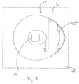
- Fig. 5 illustrated embodiment of the invention differs significantly by the basis of the Fig. 4 illustrated embodiment of the invention that the boundary surface S2 "" of the recess 20 is provided with fresnel-like prisms, which as well as the prisms in the basis of Fig. 4 illustrated embodiment run approximately perpendicular to the longitudinal direction of the gap. Also at the in Fig. 5 illustrated embodiment of the invention, the gap opens to facilitate the removal of the lens from his the passage area facing edge in the direction of the convex surface area.
- a teardrop-shaped lens 1 "'" arranged on a support 10 LED is covered by a teardrop-shaped lens 1 "'", wherein the lens 1 ""' is penetrated by a parallel to the support surface 12 of the carrier 10 extending channel.
- the boundary surfaces S3 and S4 of the channel 40 include a point angle with each other.
- a tangent to the limiting surface B delimiting the LED 15 includes a point angle with the boundary surfaces S3 and S4 of the channel 40.
- the boundary surfaces S3 and S4 of the channel 40 also form an apex angle with an outer boundary surface B ', which is penetrated by the light rays passing through the channel 40.
- the boundary surfaces S3 and S4 are partially reflective depending on the angle of the incident light (total reflection at S3, Fresnel reflection at S4). Part of the light may also be refracted at the surfaces S3 and S4, B and B '.
- the boundary surfaces S3 and S4 of the channel 40 are at the in Fig. 6 illustrated embodiment of the invention executed substantially flat. In this case, however, Entformungsschrägen are provided in the longitudinal direction of the channel 40, such that the channel extends from an opening with respect to the longitudinal direction of the channel 40 central portion to its outer ends.
- a passage region 50 is provided between the channel 40 and the support surface 12, which similarly as in the reference to the Fig. 1 explained embodiment favors a lateral light emission.
- the width of the channel can also taper starting from an edge facing the passage region 50 in the direction of the outer boundary surface of the lens 1 "'". In another embodiment, however, it can also be provided that the width of the channel increases in the direction mentioned.
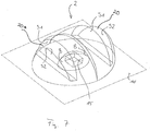
- a teardrop-shaped lens 2 is provided with two indentations 20 and 20a, which are mirror-symmetrical with respect to a LED 15 containing and extending perpendicular to the support surface 12 and parallel to the longitudinal axes of the indentations plane.
- Each of the recesses 20 and 20a is according to the embodiment of Fig. 1 executed.
- a plurality of LEDs along a straight line on the support surface 12 are arranged.
- the distances between the LEDs can be selected consistently.
- Fig. 8 only two of the LEDs arranged on a straight line are shown.
- the LEDs 15 are at the in Fig. 8 illustrated embodiment of a parallel to the straight line along which the LEDs 15 are arranged, extending linear lens covered.
- Linear lens means in the context of this invention that the lens is approximately mirror-symmetrical with respect to a line containing the straight and running perpendicular to the support surface level, wherein the lens in areas outside the indentation in a perpendicular to the Straight line, along which the LEDs 15 are arranged, extending cutting plane has constant cross-sectional shapes.
- the indentations 20 of the linear lens according to Fig. 8 are arranged centrally between the arranged on the support surface 12 LEDs.
- a passage region is provided between the edge of the indentation facing the carrier surface 12 and the carrier surface 12. The indentations widen starting from the base facing the passage area in the direction of the convex boundary surface of the linear lens 3.
- each indentation on two refractive surfaces B1 which, unlike the reference to the Fig. 1 to 7 illustrated embodiments, convex are curved.
- the shape of the refracting surfaces B1 is selected such that the light emitted by an adjacent LED is deflected in the direction of the solder of the carrier surface 12 of the LEDs. In this way, the shielding of the luminaire in a plane along the lens can be improved.
- Fig. 9 illustrated embodiment of the invention differs essentially by the basis of the Fig. 8 explained embodiment that on the boundary surfaces B1 'of the indentations a plurality of slightly convex curved cushions are formed. Through these cushions, the light of the approximately point-shaped LEDs scattered something and thus evened the light distribution curve. A corresponding homogenization can also be achieved by a slight scattering structure on the boundary surfaces B1 'of the indentations. Finally, similar effects can also be due to a low Admixture of scattering particles can be achieved in the material of the lens.
- Fig. 10 is a modification of the basis of the Fig. 8 and 9 illustrated lenses with similar function.
- prisms are executed on the boundary surfaces of the recesses, which extend in the longitudinal direction of the recess.
- Fig. 10a shows a sectional view of the lamp
- Fig. 10b shows a plan view of the lamp
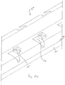
- Fig. 10c shows a perspective view of the lamp with linear lens 3 ".
- Fig. 11 is another variation of the basis of the Fig. 8 and 9 shown lights shown.
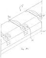
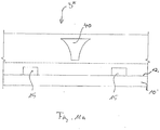
- channels 40 are formed in the lens 3 '''The channels extend along a direction perpendicular to the straight line along which the LEDs 15 are arranged and in the direction parallel to the support surface 12 of the support 10'.
- Fig. 11a shows a side view of the lamp
- Fig. 11b shows a plan view of the lamp
- Fig. 11c shows a perspective view of the lamp.
- the boundary surfaces of the channel 40 are designed as substantially flat surfaces.
- demoulding slopes are also provided in this embodiment in the sense of simplifying the production.
- the channel widens starting from a central area in the direction of the boundary surface of the linear lens 3 "."
- a passage area is provided between the channel 40 and the carrier surface 12. The channel widens starting from its edge facing the passage area in the direction of its edge facing the convex boundary surface of the lens.
- Fig. 12 For example, in the above-described sense, a linear design of a teardrop-shaped lens 2 is shown having two indentations made symmetrical to the line along which the LEDs 15 are arranged. Incidentally, the details correspond to the embodiment according to FIG Fig. 12 the luminaire according to Fig. 1 , Fig. 12a shows a sectional view of the lamp while Fig. 12b a perspective view of the lens 3 "" shows.
- Fig. 13 For example, a cone-shaped curve (elevation angle between 20 ° and 60 °) of an embodiment with two LEDs and symmetrically arranged indentations is shown. This embodiment is intended in particular for illuminating an elongated surface.
- Fig. 14 shows a teardrop-shaped lens 4, which covers an LED 15, which is arranged on a support surface 12 of a carrier 10.
- the teardrop-shaped lens 4 according to Fig. 14 is equipped with spherical air pockets on one side in a given emitting area of the LED. This leads to a targeted scattering of the light in this emission area (eg to lighten a wall area uniformly).
- the invention is not limited to the embodiments explained with reference to the drawing. Rather, it is also intended to equip the lenses of lamps according to the invention both with channels and with indentations. Additionally, in all embodiments of the invention, air pockets may also be formed in the lens.
- the support surface of the carrier 10 may be performed differently curved than in the embodiments of the invention shown in the drawing. You can with even execution of the Carrier surface preferably be designed as a boundary surface of a board.
- the support surface 12 may be wholly or partially reflective and / or be provided with surfaces of different reflectance (eg, combinations of surfaces with white solder mask, untreated board surface, provided with highly reflective plastic film (MCPET) surfaces).
- surfaces of different reflectance eg, combinations of surfaces with white solder mask, untreated board surface, provided with highly reflective plastic film (MCPET) surfaces.
- MCPTT highly reflective plastic film
- the outside of the lens facing away from the carrier surface can also be designed asymmetrically in cross-section (for example, similarly Fig. 1 ).
- the plurality of LEDs may be accommodated in a continuous receiving space whose cross-section perpendicular to the longitudinal axis of the lens has the same cross-section along this longitudinal axis (a plane surface may increase the longitudinal glare due to Fresnel reflection).
- the receiving space may be closed at the ends with a reflector.
Landscapes
- Engineering & Computer Science (AREA)
- General Engineering & Computer Science (AREA)
- Non-Portable Lighting Devices Or Systems Thereof (AREA)
Applications Claiming Priority (1)
| Application Number | Priority Date | Filing Date | Title |
|---|---|---|---|
| DE102018103547.0A DE102018103547A1 (de) | 2018-02-16 | 2018-02-16 | Leuchte |
Publications (1)
| Publication Number | Publication Date |
|---|---|
| EP3527880A1 true EP3527880A1 (fr) | 2019-08-21 |
Family
ID=65433568
Family Applications (1)
| Application Number | Title | Priority Date | Filing Date |
|---|---|---|---|
| EP19156893.0A Withdrawn EP3527880A1 (fr) | 2018-02-16 | 2019-02-13 | Luminaire |
Country Status (2)
| Country | Link |
|---|---|
| EP (1) | EP3527880A1 (fr) |
| DE (1) | DE102018103547A1 (fr) |
Cited By (3)
| Publication number | Priority date | Publication date | Assignee | Title |
|---|---|---|---|---|
| WO2023144204A1 (fr) * | 2022-01-31 | 2023-08-03 | Signify Holding B.V. | Agencement d'éclairage comprenant un corps de lentille |
| US12078340B2 (en) | 2020-11-06 | 2024-09-03 | Signify Holding B.V. | Total internal reflection lens |
| EP4471326A1 (fr) * | 2023-05-31 | 2024-12-04 | Zumtobel Lighting GmbH | Optique primaire pour éclairage homogène d'un couvercle d'un luminaire respectif |
Citations (7)
| Publication number | Priority date | Publication date | Assignee | Title |
|---|---|---|---|---|
| US20100195333A1 (en) * | 2009-01-30 | 2010-08-05 | Gary Eugene Schaefer | Led optical assembly |
| US20110292652A1 (en) * | 2010-05-31 | 2011-12-01 | Lite-On Technology Corporation | Led luminaire |
| DE102011107427A1 (de) * | 2011-07-15 | 2013-01-17 | Siteco Beleuchtungstechnik Gmbh | Deckenaufhellungsnut |
| US20150217840A1 (en) * | 2014-02-04 | 2015-08-06 | Zachary Taylor | Light Altering Rub Rail and Rub Rail Insert |
| EP2924345A1 (fr) * | 2014-03-28 | 2015-09-30 | Swarco Futurit Verkehrssignalsysteme Ges.m.b.H. | Luminaires avec distribution de lumière dissymétrique |
| US20160161084A1 (en) * | 2014-12-09 | 2016-06-09 | Lg Innotek Co., Ltd. | Lens and light emitting device module including the same |
| WO2018031613A1 (fr) * | 2016-08-12 | 2018-02-15 | Innotec, Corp. | Ensemble d'eclairage comprenant une lentille linéaire |
Family Cites Families (2)
| Publication number | Priority date | Publication date | Assignee | Title |
|---|---|---|---|---|
| DE102011111953A1 (de) * | 2011-08-30 | 2013-02-28 | Bartenbach Holding Gmbh | Tunnelleuchte |
| NL2012030C2 (en) * | 2013-12-27 | 2015-06-30 | Orga B V | Beacon light optic, beacon light. |
-
2018
- 2018-02-16 DE DE102018103547.0A patent/DE102018103547A1/de not_active Withdrawn
-
2019
- 2019-02-13 EP EP19156893.0A patent/EP3527880A1/fr not_active Withdrawn
Patent Citations (7)
| Publication number | Priority date | Publication date | Assignee | Title |
|---|---|---|---|---|
| US20100195333A1 (en) * | 2009-01-30 | 2010-08-05 | Gary Eugene Schaefer | Led optical assembly |
| US20110292652A1 (en) * | 2010-05-31 | 2011-12-01 | Lite-On Technology Corporation | Led luminaire |
| DE102011107427A1 (de) * | 2011-07-15 | 2013-01-17 | Siteco Beleuchtungstechnik Gmbh | Deckenaufhellungsnut |
| US20150217840A1 (en) * | 2014-02-04 | 2015-08-06 | Zachary Taylor | Light Altering Rub Rail and Rub Rail Insert |
| EP2924345A1 (fr) * | 2014-03-28 | 2015-09-30 | Swarco Futurit Verkehrssignalsysteme Ges.m.b.H. | Luminaires avec distribution de lumière dissymétrique |
| US20160161084A1 (en) * | 2014-12-09 | 2016-06-09 | Lg Innotek Co., Ltd. | Lens and light emitting device module including the same |
| WO2018031613A1 (fr) * | 2016-08-12 | 2018-02-15 | Innotec, Corp. | Ensemble d'eclairage comprenant une lentille linéaire |
Cited By (4)
| Publication number | Priority date | Publication date | Assignee | Title |
|---|---|---|---|---|
| US12078340B2 (en) | 2020-11-06 | 2024-09-03 | Signify Holding B.V. | Total internal reflection lens |
| WO2023144204A1 (fr) * | 2022-01-31 | 2023-08-03 | Signify Holding B.V. | Agencement d'éclairage comprenant un corps de lentille |
| EP4471326A1 (fr) * | 2023-05-31 | 2024-12-04 | Zumtobel Lighting GmbH | Optique primaire pour éclairage homogène d'un couvercle d'un luminaire respectif |
| WO2024245727A1 (fr) * | 2023-05-31 | 2024-12-05 | Zumtobel Lighting Gmbh | Optique primaire pour éclairage homogène d'un couvercle d'un luminaire respectif |
Also Published As
| Publication number | Publication date |
|---|---|
| DE102018103547A1 (de) | 2019-08-22 |
Similar Documents
| Publication | Publication Date | Title |
|---|---|---|
| EP2729838B1 (fr) | Élément optique | |
| DE102008048765B4 (de) | Beleuchtungsvorrichtung für Kraftfahrzeuge | |
| EP2622260A1 (fr) | Dispositif d'émission de lumière dirigée | |
| DE2238589B2 (de) | Lichtstreuende ebene Abdeckplatte für Deckenleuchten | |
| EP3084496A1 (fr) | Élément optique et système d'émission de lumière | |
| EP2607774A2 (fr) | Dispositif d'éclairage d'un véhicule automobile avec une surface lumineuse longue et plane | |
| DE202016002197U1 (de) | Direktstrahlende LED-Leuchte mit Entblendungsoptik | |
| EP1110031B1 (fr) | Lampe dotee d'un guide de lumiere | |
| EP2546565B1 (fr) | Encoche pour éclairage de plafond | |
| EP3527880A1 (fr) | Luminaire | |
| DE112013005281T5 (de) | Optisches Element mit einem TIR-Flächenabschnitt für verbesserte räumliche Lichtverteilung | |
| EP2796769B1 (fr) | Lampe à DEL dotée d'un système de conducteurs lumineux | |
| EP3408584B1 (fr) | Appareil d'éclairage muni d'un élément de recouvrement pyramidal ou conique | |
| EP3023689B1 (fr) | Dispositif d'éclairage | |
| EP1059484B1 (fr) | Luminaire avec répartition de l'intensité lumineuse à faisceau large | |
| DE102009060565A1 (de) | Leuchte | |
| DE102010039306A1 (de) | Anordnung zur Lichtabgabe mit Lichtlenkelement und Reflektor | |
| DE4312889B4 (de) | Vorwiegend direkt strahlende Leuchte mit einem abgehängten Lichtleitkörper | |
| DE102013211311A1 (de) | Flächenlichtquelle | |
| EP3212997B1 (fr) | Élément optique ainsi qu'ensemble d'émission de lumière comprenant un élément optique | |
| DE102007038205B4 (de) | Leuchte mit Lichtleiterplatte | |
| EP1130312B1 (fr) | Luminaire comprenant une surface d'émission de la lumière avec un centre de symétrie, notamment de forme circulaire | |
| EP2532953B1 (fr) | Plaque prismatique | |
| DE10354462B4 (de) | Leuchte mit asymmetrischer Lichtabstrahlung | |
| EP1843082B1 (fr) | Plafonnier, en particulier pour utilisation dans un couloir |
Legal Events
| Date | Code | Title | Description |
|---|---|---|---|
| PUAI | Public reference made under article 153(3) epc to a published international application that has entered the european phase |
Free format text: ORIGINAL CODE: 0009012 |
|
| STAA | Information on the status of an ep patent application or granted ep patent |
Free format text: STATUS: THE APPLICATION HAS BEEN PUBLISHED |
|
| AK | Designated contracting states |
Kind code of ref document: A1 Designated state(s): AL AT BE BG CH CY CZ DE DK EE ES FI FR GB GR HR HU IE IS IT LI LT LU LV MC MK MT NL NO PL PT RO RS SE SI SK SM TR |
|
| AX | Request for extension of the european patent |
Extension state: BA ME |
|
| STAA | Information on the status of an ep patent application or granted ep patent |
Free format text: STATUS: REQUEST FOR EXAMINATION WAS MADE |
|
| RAP1 | Party data changed (applicant data changed or rights of an application transferred) |
Owner name: SITECO GMBH |
|
| 17P | Request for examination filed |
Effective date: 20200220 |
|
| RBV | Designated contracting states (corrected) |
Designated state(s): AL AT BE BG CH CY CZ DE DK EE ES FI FR GB GR HR HU IE IS IT LI LT LU LV MC MK MT NL NO PL PT RO RS SE SI SK SM TR |
|
| STAA | Information on the status of an ep patent application or granted ep patent |
Free format text: STATUS: EXAMINATION IS IN PROGRESS |
|
| 17Q | First examination report despatched |
Effective date: 20200707 |
|
| STAA | Information on the status of an ep patent application or granted ep patent |
Free format text: STATUS: THE APPLICATION IS DEEMED TO BE WITHDRAWN |
|
| 18D | Application deemed to be withdrawn |
Effective date: 20230815 |