EP2533350B1 - Batteriemodul mit verbessertem Wärmeaustausch - Google Patents
Batteriemodul mit verbessertem Wärmeaustausch Download PDFInfo
- Publication number
- EP2533350B1 EP2533350B1 EP12162301.1A EP12162301A EP2533350B1 EP 2533350 B1 EP2533350 B1 EP 2533350B1 EP 12162301 A EP12162301 A EP 12162301A EP 2533350 B1 EP2533350 B1 EP 2533350B1
- Authority
- EP
- European Patent Office
- Prior art keywords
- battery cell
- battery
- battery module
- flange
- barrier
- Prior art date
- Legal status (The legal status is an assumption and is not a legal conclusion. Google has not performed a legal analysis and makes no representation as to the accuracy of the status listed.)
- Active
Links
Images



Classifications
-
- H—ELECTRICITY
- H01—ELECTRIC ELEMENTS
- H01M—PROCESSES OR MEANS, e.g. BATTERIES, FOR THE DIRECT CONVERSION OF CHEMICAL ENERGY INTO ELECTRICAL ENERGY
- H01M10/00—Secondary cells; Manufacture thereof
- H01M10/60—Heating or cooling; Temperature control
- H01M10/61—Types of temperature control
- H01M10/617—Types of temperature control for achieving uniformity or desired distribution of temperature
-
- H—ELECTRICITY
- H01—ELECTRIC ELEMENTS
- H01M—PROCESSES OR MEANS, e.g. BATTERIES, FOR THE DIRECT CONVERSION OF CHEMICAL ENERGY INTO ELECTRICAL ENERGY
- H01M10/00—Secondary cells; Manufacture thereof
- H01M10/60—Heating or cooling; Temperature control
- H01M10/61—Types of temperature control
- H01M10/613—Cooling or keeping cold
-
- H—ELECTRICITY
- H01—ELECTRIC ELEMENTS
- H01M—PROCESSES OR MEANS, e.g. BATTERIES, FOR THE DIRECT CONVERSION OF CHEMICAL ENERGY INTO ELECTRICAL ENERGY
- H01M10/00—Secondary cells; Manufacture thereof
- H01M10/60—Heating or cooling; Temperature control
- H01M10/62—Heating or cooling; Temperature control specially adapted for specific applications
- H01M10/625—Vehicles
-
- H—ELECTRICITY
- H01—ELECTRIC ELEMENTS
- H01M—PROCESSES OR MEANS, e.g. BATTERIES, FOR THE DIRECT CONVERSION OF CHEMICAL ENERGY INTO ELECTRICAL ENERGY
- H01M10/00—Secondary cells; Manufacture thereof
- H01M10/60—Heating or cooling; Temperature control
- H01M10/65—Means for temperature control structurally associated with the cells
- H01M10/655—Solid structures for heat exchange or heat conduction
- H01M10/6554—Rods or plates
- H01M10/6555—Rods or plates arranged between the cells
-
- H—ELECTRICITY
- H01—ELECTRIC ELEMENTS
- H01M—PROCESSES OR MEANS, e.g. BATTERIES, FOR THE DIRECT CONVERSION OF CHEMICAL ENERGY INTO ELECTRICAL ENERGY
- H01M50/00—Constructional details or processes of manufacture of the non-active parts of electrochemical cells other than fuel cells, e.g. hybrid cells
- H01M50/10—Primary casings; Jackets or wrappings
- H01M50/102—Primary casings; Jackets or wrappings characterised by their shape or physical structure
- H01M50/103—Primary casings; Jackets or wrappings characterised by their shape or physical structure prismatic or rectangular
-
- H—ELECTRICITY
- H01—ELECTRIC ELEMENTS
- H01M—PROCESSES OR MEANS, e.g. BATTERIES, FOR THE DIRECT CONVERSION OF CHEMICAL ENERGY INTO ELECTRICAL ENERGY
- H01M50/00—Constructional details or processes of manufacture of the non-active parts of electrochemical cells other than fuel cells, e.g. hybrid cells
- H01M50/20—Mountings; Secondary casings or frames; Racks, modules or packs; Suspension devices; Shock absorbers; Transport or carrying devices; Holders
-
- H—ELECTRICITY
- H01—ELECTRIC ELEMENTS
- H01M—PROCESSES OR MEANS, e.g. BATTERIES, FOR THE DIRECT CONVERSION OF CHEMICAL ENERGY INTO ELECTRICAL ENERGY
- H01M10/00—Secondary cells; Manufacture thereof
- H01M10/60—Heating or cooling; Temperature control
- H01M10/64—Heating or cooling; Temperature control characterised by the shape of the cells
- H01M10/647—Prismatic or flat cells, e.g. pouch cells
-
- Y—GENERAL TAGGING OF NEW TECHNOLOGICAL DEVELOPMENTS; GENERAL TAGGING OF CROSS-SECTIONAL TECHNOLOGIES SPANNING OVER SEVERAL SECTIONS OF THE IPC; TECHNICAL SUBJECTS COVERED BY FORMER USPC CROSS-REFERENCE ART COLLECTIONS [XRACs] AND DIGESTS
- Y02—TECHNOLOGIES OR APPLICATIONS FOR MITIGATION OR ADAPTATION AGAINST CLIMATE CHANGE
- Y02E—REDUCTION OF GREENHOUSE GAS [GHG] EMISSIONS, RELATED TO ENERGY GENERATION, TRANSMISSION OR DISTRIBUTION
- Y02E60/00—Enabling technologies; Technologies with a potential or indirect contribution to GHG emissions mitigation
- Y02E60/10—Energy storage using batteries
Definitions
- the present invention relates to a battery module, and more particularly, to a battery module including a plurality of battery cells and barriers interposed between the battery cells.
- the high-output battery module includes a plurality of battery cells connected to each other in series to configure a large-capacity battery module so as to be used to drive a high-power-required equipment, for example, a motor of an electric vehicle and the like.
- gas may be generated by a side reaction.
- the gas may change the appearance of the battery cell and accordingly, the form of the battery module is influenced, thereby preventing the battery cells from being stably fixed.
- heat is often generated and so the cells require cooling.
- JP 2009 277471 and JP 2007 280858 each disclose a battery module having barriers between adjacent cells, which include interlocking or mating faces such that adjacent barriers seal against each other.
- US 2006/049799 discloses a battery pack having spacers between adjoining battery modules to provide a cooling passage.
- US 5 756 227 discloses a battery pack having heat exchange planar members sandwiched between unit batteries.
- an object of the present invention is to provide a battery module having improved heat exchange efficiency.
- Another object of the present invention provides a battery module capable of preventing changes in the position of the battery cells by stably fixing the battery cell.
- the invention provides a battery module as set out in Claim 1.
- Preferred features of the invention are set out in Claims 2 to 15.
- a battery module can have improved heat exchange efficiency, thereby improving the lifespan thereof.
- a battery module can have improved physical stability.
- FIG. 1 is a perspective view of a battery module according to an embodiment of the present invention.
- the battery module 100 includes a plurality of battery cells 10 arranged in one direction; barriers 150 interposed between the battery cells 10; and housings 110, 120, 130, and 140 accommodating the battery cells 10 and the barriers 150.
- Each barrier 150 includes a base part 153 disposed to be parallel to the battery cells 10 and flange parts 151 and 152 contacting adjacent battery cells 10 in upper and lower portions on both sides of the base part 153.
- the base part 153 is made of a first material, and a part of each of the flange parts 151 and 152 is made of a second material different from the first material.
- Each battery cell 10 may be manufactured by sealing a battery case with a cap assembly 14 after an electrode assembly and an electrolyte are stored in the battery case.
- Each cap assembly 14 includes a positive terminal 11 and a negative terminal 12 disposed at respective ends of the cap assembly 14 and a vent 13.
- Each electrode assembly is connected via its with the positive terminal 11 and negative terminal 12 and the terminals act as conductor of energy generated by electrochemical reaction between the electrode assembly and the electrolyte. Further, the vent 13 acts as an outlet for discharging gas generated in the battery cell 10 to the outside.
- the housings 110, 120, 130, and 140 bundle the plurality of battery cells 10 and the barriers 150 interposed between the battery cells 10 together.
- the housings 110, 120, 130, and 140 include a pair of first and second end plates 110 and 120 disposed at the outside of the battery cells 10 and connection members 130 and 140 connecting the first and second end plates 110 and 120 to each other.
- the first and second end plates 110 and 120 and the connection members 130 and 140 partition a predetermined space in order to accommodate the plurality of battery cells 10 and the battery cells 10 are arranged in one direction in the partitioned space.
- the battery cells 10 are arranged in parallel, so that their major surfaces face each other.
- the positive terminals 11 or the negative terminals 12 of each two adjacent battery cells 10 are electrically connected to each other through a bus-bar 15.
- Each bus-bar 15 includes holes through which the positive terminal 11 and the negative terminal 12 of adjacent cells 10 pass.
- the bus-bar 15 in which the positive terminal 11 and the negative terminal 12 are connected by passing through the hole are fixed with nuts 16 or the like.
- connection members 130 and 140 include a pair of side plates 130 and a bottom plate 140.
- the side plates 130 serve to support both sides of the battery cells 10 and the bottom plate 140 serves to support the bottoms of the battery cells 10.
- First ends of the side plates 130 and one end of the bottom plate 140 are fastened to a first end plate 110 and opposite ends thereof are fastened to a second end plate 120 in order to connect the first and the second end plates 110 and 120.
- the fastening is performed by a bolt-nut and the like, but the invention is not limited thereto.
- the first and the second end plates 110 and 120, the side plates 130 and the bottom plate 140 act to stably fix the plurality of battery cells 10 and the barriers 150, but they are not limited to the form of this embodiment and may be variously modified. Further, the connection structure of the battery cells 10 and the number of the battery cells 10 may be variously modified according to a design of the battery module 100.
- FIG. 2A is a perspective view of a barrier interposed between battery cells according to this embodiment of the present invention and FIG. 2B is a perspective view of the barrier.
- the barrier 150 includes an intermediate part in the form of a base part 153 configured to be parallel to the battery cell 10 and flange parts 151 and 152 adapted to contact the battery cell 10 located on each side of the base part 153.
- the barrier 150 is made predominently of a first material, and a first part of each of the flange parts 151 and 152 is made of a second material different from the first material.
- the base part 153 substantially has a size corresponding to the wide front surface of the battery cell 10.
- a plurality of projections 154 are disposed on the base part 153. The projections serve to contact the adjacent battery cells 10.
- the base part 153 is adapted to be interposed between the adjacent battery cells 10 and spaced apart from the battery cell 10 by a predetermined amount by the projections 154. The projections therefore serve to provide a moving passage for a heat exchange medium.
- the flange parts 151 and 152 include first and second side flange parts 151 and 152 contacting the sides of the battery cells located on each side of the base part 153.
- the first and second side flange parts 151 and 152 are perpendicular to the base part 153.
- the base part 153 is connected to the centers of the first and second side flange parts 151 and 152 to define a T-shaped cross-section in the region of the connection.
- the first or the second side flange part 151 or 152 may include a tetragonal flat plate facing the side of the battery cell.
- first and second side flange parts each include openings 151c and 152c.
- the openings 151c and 152c include a plurality of holes spaced apart from each other in a longitudinal direction of the respective side flange part 151 or 152.
- the flange parts 151 and 152 of the barrier 150 are formed from the first material and a second part of edges of the flange parts 151 and 152 is made of the second material. Further, the barriers 150 are provided so that the flange parts 151 and 152 of adjacent barriers 150 contact each other.
- the first and second flange parts 151 and 152 include first portions 151a and 152a made of the first material and second portions 151b and 152b made of the second material and provided around edges of both sides of the first portions 151a and 152a.
- the first material may include at least one or more of stainless steel, aluminum, plastic and the second material may include an elastic member such as rubber and the like.
- Heat may be generated by repetitive charge and discharge in the battery cells, and the heat accelerates the deterioration of the battery cells and can cause serious problems such as ignition or explosion of the battery cells.
- space is provided between the battery cells 10 and the space may act as passages U1 to U2 for a heat exchange medium capable of controlling the heat generated in the battery cells 10. That is, the heat exchange medium flows in through the openings 152c of the second side flange part 152 and flows out through the openings 151c of the first side flange part 151 to exchange the heat by directly addressing the wide surface of the battery cells 10.
- the second part of the flange parts 151 and 152 act as baffles to constrain the heat exchange medium to the passages. Accordingly, the temperature of the battery cells can be efficiently controlled and the use lifespan of the battery module 100 can be lengthened.
- the barrier of the battery module provides the moving passage of the heat exchange medium by separating the battery cells and in addition, can improve the fastening property of the battery module by fixing the plurality of battery cells.
- the second portions 151b and 152b of the flange parts 151 and 152 are in contact with each other and thus, the flange parts 151 and 152 of the adjacent barriers 150 are close to each other in the sides of the battery cells 10, and the heat exchange medium can flow in or out efficiently through the openings 151c and 152c.
- FIGS. 3 to 5 This embodiment is similar to the embodiment described in FIGS. 1 to 2B , except for contents described below.
- FIG. 3 is a perspective view of a battery module according to this embodiment of the present invention
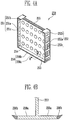
- FIG. 4A is a perspective view of a barrier according to this embodiment of the present invention
- FIG. 4B is a cross sectional view taken along line B-B of FIG. 4A .
- the battery module 200 includes a plurality of battery cells 10 arranged in one direction; barriers 250 interposed between the battery cells 10; and housings 210, 220, 230, and 240 accommodating the battery cells 10 and the barriers 250.
- Each barrier 250 includes a base part 253 disposed to be parallel to the battery cells 10 and including projections 254 and flange parts 251, 252, 253, and 254 contacting adjacent battery cells 10 in upper and lower portions of both sides of the base part 253.
- Each barrier 250 may be made predominently of at least one or more of stainless steel, aluminum and plastic.
- the flange parts of the barrier 250 may be made of an elastic member such as rubber and the like.
- the flange parts 251, 252, 253, and 254 include first and second side flange parts 251 and 252 provided at the both sides of the base part 253 and an upper flange part 255 and a lower flange part 256 respectively separately connected to an upper portion and a lower portion of the first and second side flange parts 251 and 252.
- the upper flange part 255 connects the first and second side flange parts 251 and 252 and contacts the upper side of the adjacent battery cells 10.
- positive and negative terminals 11 and 12 and a vent 14 are provided and exposed to the outside thereof.
- the upper flange part 254 since the upper flange part 254 is nearly not influenced on the load of the battery cell due to a structural characteristic thereof, an additional member for supporting the upper side is not required at the upper side of the battery cells 10.
- the upper flange part 255 may be made of an elastic member such as rubber and the like and may be made of only the elastic member.
- the upper flange part 255 is in close contact with the cap assembly 14 of the battery cells 10, thereby acting as a outlet and preventing a leakage of the heat exchange medium at the upper side of the battery module 200.
- the lower flange part 256 connects the first and second side flange parts 251 and 252 and corresponds to the bottom of the battery cells 10.
- the lower flange part 256 extends by the same width as the first and second side flange parts 251 and 252.
- the first portion 256a of the lower flange part 256 may be made of at least any one of hard stainless steel, aluminum and plastic.
- the second portion 256b located at edge regions of both sides of the first portion 256a may be made of an elastic member such as rubber and the like.
- the second portions 256b of the lower flange parts 256 of the adjacent barriers 250 are in contact with each other, thereby preventing a leakage of the heat exchange medium at the lower side of the battery module 200.
- the edges of the flange parts 251, 252, 253, and 254 have a substantially triangular cross-section which is gradually tapered toward an edge region thereof.
- the second portion has a generally triangular shape of cross-section.
- the second portions of each of the flange parts 251, 252, 253, and 254 are formed so as to be inclined toward the battery cell side.
- the second portions 256b of the lower flange part 256 may be made of an elastic member and the like, thereby improving compactibility as compared with the first portion. Accordingly, the lower flange part 256 is connected with base part 253 in the center the first portion 256a to support the bottom of the battery cells 10.
- the shape of the second portion 256b is not limited to the lower flange part 256 and may be applied to the first and second side flange parts 251 and 252 and the upper flange part 255.
- Heat exchange efficiency between the battery cells 10 can be improved due to the elastic member provided in the flange parts 251, 252, 253, and 254 of the barriers 250 and the shape of the edges of the flange parts 251, 252, 253, and 254, thereby extending a useful lifespan of the battery module 200 and reducing the cost of the battery module 200.
- FIG. 5 is a cross sectional view taken along line A-A of FIG. 3 .
- the upper flange part 255 made of an elastic member is in close contact with the upper sides of the battery cells 10.
- the lower flange part 256 is provided at the lower side of the battery cells and the lower flange part 256 is in close contact with the bottoms of the battery cells 10.
- the heat exchange medium may flow into or out from the battery module 200 through the openings 251a and 252b of the first and second flange parts 251 and 252. Therefore, unnecessary waste of the heat exchange medium used for cooling and heating the battery cell 10 can be reduced and heat exchange efficiency of the battery cell 10 can be improved.
Landscapes
- Chemical & Material Sciences (AREA)
- Chemical Kinetics & Catalysis (AREA)
- Electrochemistry (AREA)
- General Chemical & Material Sciences (AREA)
- Engineering & Computer Science (AREA)
- Manufacturing & Machinery (AREA)
- Battery Mounting, Suspending (AREA)
- Secondary Cells (AREA)
Claims (15)
- Batteriemodul, umfassend:eine Vielzahl von Batteriezellen (10), die nacheinander in einer ersten Richtung angeordnet sind; undeine erste Trennwand (150);wobei die erste Trennwand (150) ein erstes Zwischenteil (153), das sich zwischen einer ersten Batteriezelle und einer zweiten Batteriezelle befindet, und ein erstes Flanschteil (151) umfasst, das einen ersten Flanschabschnitt (151a) umfasst;wobei sich der erste Flanschabschnitt (151a) über einen Oberflächenabschnitt der ersten Batteriezelle erstreckt und sich über einen Oberflächenabschnitt der zweiten Batteriezelle erstreckt;dadurch gekennzeichnet, dass ein erstes Prallblechteil (151b) an den Kanten des ersten Flanschabschnitts (151a) vorgesehen ist, das sich über die Oberflächenabschnitte der ersten Batteriezelle und der zweiten Batteriezelle erstreckt und mit den Oberflächenabschnitten der ersten Batteriezelle und der zweiten Batteriezelle einen Kontakt herstellt,wobei das erste Prallblechteil (151b) ein flexibles Material und/oder ein elastomeres Material umfasst.
- Batteriemodul nach Anspruch 1, wobei der erste Flanschabschnitt einen Flanschkörper (151a) umfasst, auf dem sich das erste Prallblechteil (151b) befindet.
- Batteriemodul nach Anspruch 2, wobei jeder Flanschkörper (151a) einen oder mehrere aus Edelstahl, Aluminium und einem Kunststoffmaterial umfasst.
- Batteriemodul nach einem vorhergehenden Anspruch, wobei das erste Flanschteil (151) mindestens eine Öffnung (151c) umfasst, um einem Kühlmedium den Zugang zu einem Raum zwischen dem ersten Zwischenteil (153) und mindestens entweder der ersten Batteriezellen oder der zweiten Batteriezelle zu ermöglichen.
- Batteriemodul nach Anspruch 4, wobei die Öffnung (151c) mit einem ersten Raum zwischen der Trennwand (150) und der ersten Batteriezelle und einem zweiten Raum zwischen der Trennwand (150) und der zweiten Batteriezelle verbunden ist.
- Batteriemodul nach einem der Ansprüche 4 bis 5, wobei die erste Trennwand (150) eine Abstandshalteranordnung (154) zum Abstandshalten mindestens entweder der ersten Batteriezelle oder der zweiten Batteriezelle vom ersten Zwischenteil (153) umfasst, um so einen Strömungsweg für ein Kühlmedium zwischen dem ersten Zwischenteil (153) und der oder jeder der Batteriezellen bereitzustellen.
- Batteriemodul nach einem vorhergehenden Anspruch, wobei sich das erste Flanschteil (151) auf einer Seitenfläche des Batteriemoduls befindet.
- Batteriemodul nach Anspruch 7, wobei die erste Trennwand (150) ein zweites Flanschteil (152) auf einer gegenüberliegenden Seitenfläche des Batteriemoduls zum ersten Flanschteil (151) umfasst.
- Batteriemodul nach Anspruch 8, wobei das zweite Flanschteil (152) einen weiteren ersten Flanschabschnitt (152a) umfasst;
wobei sich der weitere erste Flanschabschnitt (152a) über einen Oberflächenabschnitt der ersten Batteriezelle erstreckt und sich über einen Oberflächenabschnitt der zweiten Batteriezelle erstreckt, wobei ein zweiter Prallblechabschnitt (152b) an jedem der Ränder des weiteren ersten Flanschabschnitts (152a) bereitgestellt wird, der sich über die Oberflächenabschnitte der ersten Batteriezelle und der zweiten Batteriezelle erstreckt und mit den Oberflächenabschnitten der ersten Batteriezelle und der zweiten Batteriezelle einen Kontakt herstellt,
wobei der zweite Prallblechabschnitt (152b) ein flexibles Material und/oder ein elastomeres Material umfasst. - Batteriemodul nach Anspruch 7, 8 oder 9, wobei die erste Trennwand (150) ferner ein unteres Flanschteil (256) umfasst, das auf einer Bodenfläche des Batteriemoduls angeordnet ist und sich im Allgemeinen senkrecht zum ersten Flanschteil (151) erstreckt und einen dritten Flanschabschnitt (256a) umfasst, wobei ein drittes Prallblechteil (256b) an jeder der Kanten des dritten Flanschabschnitts (256a) bereitgestellt wird.
- Batteriemodul nach einem vorhergehenden Anspruch, wobei mindestens eines der Prallblechabschnitte (151b, 152b, 256b) einen Querschnitt aufweist, der sich zu einer distalen Kante hin verjüngt.
- Batteriemodul nach einem der Ansprüche 7 bis 10, wobei die erste Trennwand (150) ferner ein oberes Flanschteil (255) umfasst, das sich auf einer Oberseite des Batteriemoduls befindet und sich im Allgemeinen senkrecht zu dem ersten Flanschteil (151) erstreckt.
- Batteriemodul nach einem vorhergehenden Anspruch, wobei sich der erste und der zweite Flanschabschnitt (151a, 152a) voneinander weg in einer Richtung erstrecken, die im Wesentlichen senkrecht zu einer Ebene verläuft, die die erste Batteriezelle von der zweiten Batteriezelle trennt.
- Batteriemodul nach einem vorhergehenden Anspruch, umfassend eine zweite Trennwand;
wobei die zweite Trennwand ein zweites Zwischenteil, das sich zwischen der ersten Batteriezelle und einer dritten Batteriezelle befindet, und ein drittes Flanschteil umfasst, das einen weiteren ersten Flanschabschnitt umfasst;
wobei der weitere erste Flanschabschnitt sich über einen Oberflächenabschnitt der ersten Batteriezelle erstreckt und sich über einen Oberflächenabschnitt der dritten Batteriezelle erstreckt, wobei ein vierter Prallblechabschnitt an den Kanten des weiteren ersten Flanschabschnitts vorgesehen ist, der sich über die Oberflächenabschnitte der ersten Batteriezelle und der dritten Batteriezelle erstreckt und mit den Oberflächenabschnitten der ersten Batteriezelle und der dritten Batteriezelle einen Kontakt herstellt. - Batteriezelle nach Anspruch 13, wobei das vierte Prallblechteil die ersten oder zweiten Prallblechabschnitte (151b, 152b) in dem Oberflächenabschnitt der ersten Batteriezelle kontaktiert.
Applications Claiming Priority (2)
| Application Number | Priority Date | Filing Date | Title |
|---|---|---|---|
| US201161495660P | 2011-06-10 | 2011-06-10 | |
| US13/337,729 US9793584B2 (en) | 2011-06-10 | 2011-12-27 | Battery module |
Publications (2)
| Publication Number | Publication Date |
|---|---|
| EP2533350A1 EP2533350A1 (de) | 2012-12-12 |
| EP2533350B1 true EP2533350B1 (de) | 2020-05-06 |
Family
ID=45930609
Family Applications (1)
| Application Number | Title | Priority Date | Filing Date |
|---|---|---|---|
| EP12162301.1A Active EP2533350B1 (de) | 2011-06-10 | 2012-03-29 | Batteriemodul mit verbessertem Wärmeaustausch |
Country Status (5)
| Country | Link |
|---|---|
| US (2) | US9793584B2 (de) |
| EP (1) | EP2533350B1 (de) |
| JP (1) | JP6126801B2 (de) |
| KR (1) | KR101658026B1 (de) |
| CN (1) | CN102820492B (de) |
Families Citing this family (30)
| Publication number | Priority date | Publication date | Assignee | Title |
|---|---|---|---|---|
| JP6205807B2 (ja) * | 2013-04-08 | 2017-10-04 | 株式会社Gsユアサ | バッテリモジュール |
| JP5958420B2 (ja) * | 2013-05-29 | 2016-08-02 | トヨタ自動車株式会社 | 電池乾燥装置及び電池の製造方法 |
| US9484607B2 (en) * | 2013-08-05 | 2016-11-01 | Samsung Sdi Co., Ltd. | Battery module |
| JP6279290B2 (ja) * | 2013-11-15 | 2018-02-14 | 株式会社東芝 | 電池モジュール |
| JP6245038B2 (ja) | 2014-03-31 | 2017-12-13 | 株式会社Gsユアサ | 蓄電装置 |
| CN106233497B (zh) | 2014-04-25 | 2019-04-26 | 三洋电机株式会社 | 电池组及具有电池组的车辆 |
| DE102014221724B4 (de) | 2014-07-11 | 2025-01-23 | Robert Bosch Gmbh | Vorrichtung zur Anordnung einer Vielzahl von Batteriezellen |
| CN105322113B (zh) | 2014-07-30 | 2019-09-27 | 株式会社杰士汤浅国际 | 蓄电装置 |
| CN105322214B (zh) | 2014-07-30 | 2019-08-09 | 株式会社杰士汤浅国际 | 蓄电装置 |
| US10199695B2 (en) | 2014-08-18 | 2019-02-05 | Johnson Controls Technology Company | Battery module with restrained battery cells utilizing a heat exchanger |
| US9640788B2 (en) * | 2014-08-22 | 2017-05-02 | Ford Global Technologies, Llc | Battery cell separator having contoured profile |
| US10611264B2 (en) * | 2015-03-23 | 2020-04-07 | Ford Global Technologies, Llc | Electrified vehicle busbar assembly |
| JP6544015B2 (ja) * | 2015-04-17 | 2019-07-17 | 株式会社豊田自動織機 | 電池ホルダ |
| US10910613B2 (en) * | 2015-06-12 | 2021-02-02 | Ford Global Technologies, Llc | Battery cell retention assembly and method |
| US9929441B2 (en) * | 2015-10-02 | 2018-03-27 | Bosch Battery Systems, Llc | Elastic bellows and battery cell assemblies including same |
| DE102017217118A1 (de) * | 2017-09-26 | 2019-03-28 | Robert Bosch Gmbh | Batteriemodul |
| JP7174923B2 (ja) * | 2018-01-17 | 2022-11-18 | パナソニックIpマネジメント株式会社 | 蓄電装置 |
| DE102018212627A1 (de) * | 2018-07-27 | 2020-01-30 | Mahle International Gmbh | Akkumulatoranordnung |
| DE102018212626A1 (de) * | 2018-07-27 | 2020-01-30 | Mahle International Gmbh | Akkumulatoranordnung |
| CN210006793U (zh) * | 2019-07-04 | 2020-01-31 | 江苏时代新能源科技有限公司 | 电池模组 |
| WO2021002128A1 (ja) * | 2019-07-04 | 2021-01-07 | 株式会社Gsユアサ | 蓄電装置 |
| DE102019210193A1 (de) * | 2019-07-10 | 2021-01-14 | Mahle International Gmbh | Energiespeichermodul |
| DE102019210191A1 (de) * | 2019-07-10 | 2021-01-14 | Mahle International Gmbh | Energiespeicherzellenstapel |
| US11502325B2 (en) * | 2019-12-19 | 2022-11-15 | Toyota Motor Engineering & Manufacturing North America, Inc. | Battery stack assemblies and methods for replacing a battery cell |
| JP7430537B2 (ja) * | 2020-01-24 | 2024-02-13 | 株式会社豊田自動織機 | 蓄電装置 |
| WO2022009225A1 (en) * | 2020-07-08 | 2022-01-13 | Tvs Motor Company Limited | A battery pack |
| ES2911761B2 (es) * | 2020-11-19 | 2022-10-14 | Neptury Tech S L | Acumulador de energia electrica con refrigeracion interna |
| EP4496089A4 (de) | 2022-03-16 | 2025-06-11 | GS Yuasa International Ltd. | Elektrische energiespeichervorrichtung |
| FR3140482A1 (fr) * | 2022-09-29 | 2024-04-05 | Valeo Systemes Thermiques | Espaceur pour cellules de batterie, configuré pour former une partie du circuit de circulation étanche au fluide caloporteur |
| JP7635473B1 (ja) * | 2023-08-08 | 2025-02-25 | Nok株式会社 | 電池及び緩衝シート |
Family Cites Families (24)
| Publication number | Priority date | Publication date | Assignee | Title |
|---|---|---|---|---|
| US5480743A (en) * | 1993-08-17 | 1996-01-02 | Acr Electronics, Inc. | Bipolar compression cell for a water-activated battery |
| JP3451142B2 (ja) | 1994-11-18 | 2003-09-29 | 本田技研工業株式会社 | 温度制御機構を備えたバッテリ組立体 |
| JP4570888B2 (ja) * | 2004-03-18 | 2010-10-27 | 富士重工業株式会社 | 蓄電体装置 |
| JP2006073461A (ja) | 2004-09-06 | 2006-03-16 | Toyota Motor Corp | 組電池 |
| KR100876458B1 (ko) * | 2004-12-24 | 2008-12-29 | 주식회사 엘지화학 | 신규한 구조의 전지 카트리지와 그것을 포함하고 있는개방형 전지 모듈 |
| JP4457931B2 (ja) * | 2005-03-17 | 2010-04-28 | トヨタ自動車株式会社 | 電池モジュール |
| WO2006135008A1 (ja) * | 2005-06-17 | 2006-12-21 | Nec Lamilion Energy, Ltd. | 電気デバイス集合体およびフィルム外装電気デバイス構造体 |
| JP2007048750A (ja) * | 2005-08-10 | 2007-02-22 | Samsung Sdi Co Ltd | 電池モジュール |
| KR100696669B1 (ko) | 2005-08-10 | 2007-03-19 | 삼성에스디아이 주식회사 | 이차 전지 모듈 |
| KR101181849B1 (ko) | 2005-09-05 | 2012-09-11 | 삼성에스디아이 주식회사 | 이차 전지 모듈과 이차 전지 모듈의 격벽 |
| JP5118817B2 (ja) | 2006-04-11 | 2013-01-16 | トヨタ自動車株式会社 | 2次電池の保持構造 |
| JP2008166191A (ja) * | 2006-12-28 | 2008-07-17 | Sanyo Electric Co Ltd | 電池パック |
| JP2009187781A (ja) * | 2008-02-06 | 2009-08-20 | Toshiba Corp | 組電池 |
| FR2929760B1 (fr) | 2008-04-08 | 2010-10-01 | Vehicules Electr Soc D | Batterie electrique comprenant des elements generateurs souples et un systeme de conditionnement mecanique et thermique desdits elements |
| JP5108618B2 (ja) | 2008-05-14 | 2012-12-26 | トヨタ自動車株式会社 | 電池ホルダ |
| JP2010108733A (ja) | 2008-10-30 | 2010-05-13 | Toshiba Corp | 電池モジュール |
| JP5412804B2 (ja) | 2008-11-19 | 2014-02-12 | 日産自動車株式会社 | 燃料電池スタック |
| JP2011034775A (ja) | 2009-07-31 | 2011-02-17 | Sanyo Electric Co Ltd | 組電池の冷却構造、及び、バッテリーシステム |
| US8399119B2 (en) * | 2009-08-28 | 2013-03-19 | Lg Chem, Ltd. | Battery module and method for cooling the battery module |
| KR101084933B1 (ko) * | 2009-12-04 | 2011-11-17 | 삼성에스디아이 주식회사 | 이차 전지 모듈 및 이차 전지 모듈의 전지 스페이서 |
| JP2011171029A (ja) * | 2010-02-17 | 2011-09-01 | Sanyo Electric Co Ltd | 電池モジュール |
| CN201758165U (zh) | 2010-06-30 | 2011-03-09 | 中国电力科学研究院 | 一种电池组冷却结构 |
| US9356268B2 (en) * | 2011-01-10 | 2016-05-31 | Samsung Sdi Co., Ltd. | Battery module |
| JP5601283B2 (ja) * | 2011-06-17 | 2014-10-08 | トヨタ自動車株式会社 | 蓄電装置、スペーサ |
-
2011
- 2011-12-27 US US13/337,729 patent/US9793584B2/en active Active
-
2012
- 2012-03-05 CN CN201210055375.9A patent/CN102820492B/zh active Active
- 2012-03-29 EP EP12162301.1A patent/EP2533350B1/de active Active
- 2012-05-31 KR KR1020120058367A patent/KR101658026B1/ko active Active
- 2012-06-08 JP JP2012130683A patent/JP6126801B2/ja active Active
-
2017
- 2017-10-04 US US15/724,917 patent/US10658712B2/en active Active
Non-Patent Citations (1)
| Title |
|---|
| None * |
Also Published As
| Publication number | Publication date |
|---|---|
| US9793584B2 (en) | 2017-10-17 |
| KR101658026B1 (ko) | 2016-09-20 |
| JP2013004523A (ja) | 2013-01-07 |
| EP2533350A1 (de) | 2012-12-12 |
| JP6126801B2 (ja) | 2017-05-10 |
| US20120315519A1 (en) | 2012-12-13 |
| CN102820492B (zh) | 2018-09-07 |
| US10658712B2 (en) | 2020-05-19 |
| CN102820492A (zh) | 2012-12-12 |
| US20180034118A1 (en) | 2018-02-01 |
Similar Documents
| Publication | Publication Date | Title |
|---|---|---|
| EP2533350B1 (de) | Batteriemodul mit verbessertem Wärmeaustausch | |
| US8932749B2 (en) | Battery module | |
| EP3453060B1 (de) | Kühlanordnung für eine energiespeichervorrichtung | |
| CN101322281B (zh) | 高冷却效率的电池模块 | |
| EP3062361B1 (de) | Sekundärbatterierahmen und batteriemodul, das diesen enthält | |
| EP2793289B1 (de) | Batteriemodul | |
| CN103890997B (zh) | 中大型电池组组件 | |
| US9166260B2 (en) | Battery module | |
| KR101833526B1 (ko) | 수냉식 냉각구조를 포함하는 전지모듈 | |
| EP2557612B1 (de) | Batteriemodul | |
| US9406916B2 (en) | Battery module | |
| US20120263991A1 (en) | Battery pack | |
| US20200176838A1 (en) | Battery module | |
| JP2019525397A (ja) | 電池サブモジュールキャリア、電池サブモジュール、電池システムおよび自動車 | |
| US20140356664A1 (en) | Battery module | |
| US20120237804A1 (en) | Battery pack | |
| KR101240702B1 (ko) | 배리어의 구조가 개선된 배터리 모듈 | |
| KR20240077246A (ko) | 배터리 팩 | |
| EP4535512A2 (de) | Batteriepack und fahrzeug damit | |
| EP2797159B1 (de) | Batteriepack | |
| KR20210072999A (ko) | 에너지 밀도와 방열효과가 향상된 전지 팩 |
Legal Events
| Date | Code | Title | Description |
|---|---|---|---|
| PUAI | Public reference made under article 153(3) epc to a published international application that has entered the european phase |
Free format text: ORIGINAL CODE: 0009012 |
|
| 17P | Request for examination filed |
Effective date: 20120329 |
|
| AK | Designated contracting states |
Kind code of ref document: A1 Designated state(s): AL AT BE BG CH CY CZ DE DK EE ES FI FR GB GR HR HU IE IS IT LI LT LU LV MC MK MT NL NO PL PT RO RS SE SI SK SM TR |
|
| AX | Request for extension of the european patent |
Extension state: BA ME |
|
| RAP1 | Party data changed (applicant data changed or rights of an application transferred) |
Owner name: SAMSUNG SDI CO., LTD. Owner name: ROBERT BOSCH GMBH |
|
| STAA | Information on the status of an ep patent application or granted ep patent |
Free format text: STATUS: EXAMINATION IS IN PROGRESS |
|
| 17Q | First examination report despatched |
Effective date: 20161124 |
|
| REG | Reference to a national code |
Ref country code: DE Ref legal event code: R079 Ref document number: 602012069816 Country of ref document: DE Free format text: PREVIOUS MAIN CLASS: H01M0010500000 Ipc: H01M0010625000 |
|
| RIC1 | Information provided on ipc code assigned before grant |
Ipc: H01M 10/6555 20140101ALI20190917BHEP Ipc: H01M 10/613 20140101ALI20190917BHEP Ipc: H01M 10/625 20140101AFI20190917BHEP |
|
| GRAP | Despatch of communication of intention to grant a patent |
Free format text: ORIGINAL CODE: EPIDOSNIGR1 |
|
| STAA | Information on the status of an ep patent application or granted ep patent |
Free format text: STATUS: GRANT OF PATENT IS INTENDED |
|
| INTG | Intention to grant announced |
Effective date: 20191031 |
|
| GRAS | Grant fee paid |
Free format text: ORIGINAL CODE: EPIDOSNIGR3 |
|
| GRAA | (expected) grant |
Free format text: ORIGINAL CODE: 0009210 |
|
| STAA | Information on the status of an ep patent application or granted ep patent |
Free format text: STATUS: THE PATENT HAS BEEN GRANTED |
|
| RAP1 | Party data changed (applicant data changed or rights of an application transferred) |
Owner name: ROBERT BOSCH GMBH Owner name: SAMSUNG SDI CO., LTD. |
|
| AK | Designated contracting states |
Kind code of ref document: B1 Designated state(s): AL AT BE BG CH CY CZ DE DK EE ES FI FR GB GR HR HU IE IS IT LI LT LU LV MC MK MT NL NO PL PT RO RS SE SI SK SM TR |
|
| REG | Reference to a national code |
Ref country code: GB Ref legal event code: FG4D |
|
| REG | Reference to a national code |
Ref country code: CH Ref legal event code: EP Ref country code: AT Ref legal event code: REF Ref document number: 1268308 Country of ref document: AT Kind code of ref document: T Effective date: 20200515 |
|
| REG | Reference to a national code |
Ref country code: DE Ref legal event code: R096 Ref document number: 602012069816 Country of ref document: DE |
|
| REG | Reference to a national code |
Ref country code: IE Ref legal event code: FG4D |
|
| REG | Reference to a national code |
Ref country code: LT Ref legal event code: MG4D |
|
| REG | Reference to a national code |
Ref country code: NL Ref legal event code: MP Effective date: 20200506 |
|
| PG25 | Lapsed in a contracting state [announced via postgrant information from national office to epo] |
Ref country code: IS Free format text: LAPSE BECAUSE OF FAILURE TO SUBMIT A TRANSLATION OF THE DESCRIPTION OR TO PAY THE FEE WITHIN THE PRESCRIBED TIME-LIMIT Effective date: 20200906 Ref country code: LT Free format text: LAPSE BECAUSE OF FAILURE TO SUBMIT A TRANSLATION OF THE DESCRIPTION OR TO PAY THE FEE WITHIN THE PRESCRIBED TIME-LIMIT Effective date: 20200506 Ref country code: GR Free format text: LAPSE BECAUSE OF FAILURE TO SUBMIT A TRANSLATION OF THE DESCRIPTION OR TO PAY THE FEE WITHIN THE PRESCRIBED TIME-LIMIT Effective date: 20200807 Ref country code: SE Free format text: LAPSE BECAUSE OF FAILURE TO SUBMIT A TRANSLATION OF THE DESCRIPTION OR TO PAY THE FEE WITHIN THE PRESCRIBED TIME-LIMIT Effective date: 20200506 Ref country code: NO Free format text: LAPSE BECAUSE OF FAILURE TO SUBMIT A TRANSLATION OF THE DESCRIPTION OR TO PAY THE FEE WITHIN THE PRESCRIBED TIME-LIMIT Effective date: 20200806 Ref country code: FI Free format text: LAPSE BECAUSE OF FAILURE TO SUBMIT A TRANSLATION OF THE DESCRIPTION OR TO PAY THE FEE WITHIN THE PRESCRIBED TIME-LIMIT Effective date: 20200506 Ref country code: PT Free format text: LAPSE BECAUSE OF FAILURE TO SUBMIT A TRANSLATION OF THE DESCRIPTION OR TO PAY THE FEE WITHIN THE PRESCRIBED TIME-LIMIT Effective date: 20200907 |
|
| PG25 | Lapsed in a contracting state [announced via postgrant information from national office to epo] |
Ref country code: RS Free format text: LAPSE BECAUSE OF FAILURE TO SUBMIT A TRANSLATION OF THE DESCRIPTION OR TO PAY THE FEE WITHIN THE PRESCRIBED TIME-LIMIT Effective date: 20200506 Ref country code: HR Free format text: LAPSE BECAUSE OF FAILURE TO SUBMIT A TRANSLATION OF THE DESCRIPTION OR TO PAY THE FEE WITHIN THE PRESCRIBED TIME-LIMIT Effective date: 20200506 Ref country code: LV Free format text: LAPSE BECAUSE OF FAILURE TO SUBMIT A TRANSLATION OF THE DESCRIPTION OR TO PAY THE FEE WITHIN THE PRESCRIBED TIME-LIMIT Effective date: 20200506 Ref country code: BG Free format text: LAPSE BECAUSE OF FAILURE TO SUBMIT A TRANSLATION OF THE DESCRIPTION OR TO PAY THE FEE WITHIN THE PRESCRIBED TIME-LIMIT Effective date: 20200806 |
|
| REG | Reference to a national code |
Ref country code: AT Ref legal event code: MK05 Ref document number: 1268308 Country of ref document: AT Kind code of ref document: T Effective date: 20200506 |
|
| PG25 | Lapsed in a contracting state [announced via postgrant information from national office to epo] |
Ref country code: AL Free format text: LAPSE BECAUSE OF FAILURE TO SUBMIT A TRANSLATION OF THE DESCRIPTION OR TO PAY THE FEE WITHIN THE PRESCRIBED TIME-LIMIT Effective date: 20200506 Ref country code: NL Free format text: LAPSE BECAUSE OF FAILURE TO SUBMIT A TRANSLATION OF THE DESCRIPTION OR TO PAY THE FEE WITHIN THE PRESCRIBED TIME-LIMIT Effective date: 20200506 |
|
| PG25 | Lapsed in a contracting state [announced via postgrant information from national office to epo] |
Ref country code: EE Free format text: LAPSE BECAUSE OF FAILURE TO SUBMIT A TRANSLATION OF THE DESCRIPTION OR TO PAY THE FEE WITHIN THE PRESCRIBED TIME-LIMIT Effective date: 20200506 Ref country code: ES Free format text: LAPSE BECAUSE OF FAILURE TO SUBMIT A TRANSLATION OF THE DESCRIPTION OR TO PAY THE FEE WITHIN THE PRESCRIBED TIME-LIMIT Effective date: 20200506 Ref country code: CZ Free format text: LAPSE BECAUSE OF FAILURE TO SUBMIT A TRANSLATION OF THE DESCRIPTION OR TO PAY THE FEE WITHIN THE PRESCRIBED TIME-LIMIT Effective date: 20200506 Ref country code: RO Free format text: LAPSE BECAUSE OF FAILURE TO SUBMIT A TRANSLATION OF THE DESCRIPTION OR TO PAY THE FEE WITHIN THE PRESCRIBED TIME-LIMIT Effective date: 20200506 Ref country code: DK Free format text: LAPSE BECAUSE OF FAILURE TO SUBMIT A TRANSLATION OF THE DESCRIPTION OR TO PAY THE FEE WITHIN THE PRESCRIBED TIME-LIMIT Effective date: 20200506 Ref country code: AT Free format text: LAPSE BECAUSE OF FAILURE TO SUBMIT A TRANSLATION OF THE DESCRIPTION OR TO PAY THE FEE WITHIN THE PRESCRIBED TIME-LIMIT Effective date: 20200506 Ref country code: SM Free format text: LAPSE BECAUSE OF FAILURE TO SUBMIT A TRANSLATION OF THE DESCRIPTION OR TO PAY THE FEE WITHIN THE PRESCRIBED TIME-LIMIT Effective date: 20200506 Ref country code: IT Free format text: LAPSE BECAUSE OF FAILURE TO SUBMIT A TRANSLATION OF THE DESCRIPTION OR TO PAY THE FEE WITHIN THE PRESCRIBED TIME-LIMIT Effective date: 20200506 |
|
| REG | Reference to a national code |
Ref country code: DE Ref legal event code: R097 Ref document number: 602012069816 Country of ref document: DE |
|
| PG25 | Lapsed in a contracting state [announced via postgrant information from national office to epo] |
Ref country code: PL Free format text: LAPSE BECAUSE OF FAILURE TO SUBMIT A TRANSLATION OF THE DESCRIPTION OR TO PAY THE FEE WITHIN THE PRESCRIBED TIME-LIMIT Effective date: 20200506 Ref country code: SK Free format text: LAPSE BECAUSE OF FAILURE TO SUBMIT A TRANSLATION OF THE DESCRIPTION OR TO PAY THE FEE WITHIN THE PRESCRIBED TIME-LIMIT Effective date: 20200506 |
|
| PLBE | No opposition filed within time limit |
Free format text: ORIGINAL CODE: 0009261 |
|
| STAA | Information on the status of an ep patent application or granted ep patent |
Free format text: STATUS: NO OPPOSITION FILED WITHIN TIME LIMIT |
|
| 26N | No opposition filed |
Effective date: 20210209 |
|
| PG25 | Lapsed in a contracting state [announced via postgrant information from national office to epo] |
Ref country code: SI Free format text: LAPSE BECAUSE OF FAILURE TO SUBMIT A TRANSLATION OF THE DESCRIPTION OR TO PAY THE FEE WITHIN THE PRESCRIBED TIME-LIMIT Effective date: 20200506 |
|
| PG25 | Lapsed in a contracting state [announced via postgrant information from national office to epo] |
Ref country code: MC Free format text: LAPSE BECAUSE OF FAILURE TO SUBMIT A TRANSLATION OF THE DESCRIPTION OR TO PAY THE FEE WITHIN THE PRESCRIBED TIME-LIMIT Effective date: 20200506 |
|
| REG | Reference to a national code |
Ref country code: CH Ref legal event code: PL |
|
| REG | Reference to a national code |
Ref country code: BE Ref legal event code: MM Effective date: 20210331 |
|
| PG25 | Lapsed in a contracting state [announced via postgrant information from national office to epo] |
Ref country code: CH Free format text: LAPSE BECAUSE OF NON-PAYMENT OF DUE FEES Effective date: 20210331 Ref country code: LI Free format text: LAPSE BECAUSE OF NON-PAYMENT OF DUE FEES Effective date: 20210331 Ref country code: LU Free format text: LAPSE BECAUSE OF NON-PAYMENT OF DUE FEES Effective date: 20210329 Ref country code: IE Free format text: LAPSE BECAUSE OF NON-PAYMENT OF DUE FEES Effective date: 20210329 |
|
| PG25 | Lapsed in a contracting state [announced via postgrant information from national office to epo] |
Ref country code: BE Free format text: LAPSE BECAUSE OF NON-PAYMENT OF DUE FEES Effective date: 20210331 |
|
| PG25 | Lapsed in a contracting state [announced via postgrant information from national office to epo] |
Ref country code: HU Free format text: LAPSE BECAUSE OF FAILURE TO SUBMIT A TRANSLATION OF THE DESCRIPTION OR TO PAY THE FEE WITHIN THE PRESCRIBED TIME-LIMIT; INVALID AB INITIO Effective date: 20120329 Ref country code: CY Free format text: LAPSE BECAUSE OF FAILURE TO SUBMIT A TRANSLATION OF THE DESCRIPTION OR TO PAY THE FEE WITHIN THE PRESCRIBED TIME-LIMIT Effective date: 20200506 |
|
| P01 | Opt-out of the competence of the unified patent court (upc) registered |
Effective date: 20230530 |
|
| PG25 | Lapsed in a contracting state [announced via postgrant information from national office to epo] |
Ref country code: MK Free format text: LAPSE BECAUSE OF FAILURE TO SUBMIT A TRANSLATION OF THE DESCRIPTION OR TO PAY THE FEE WITHIN THE PRESCRIBED TIME-LIMIT Effective date: 20200506 |
|
| PG25 | Lapsed in a contracting state [announced via postgrant information from national office to epo] |
Ref country code: TR Free format text: LAPSE BECAUSE OF FAILURE TO SUBMIT A TRANSLATION OF THE DESCRIPTION OR TO PAY THE FEE WITHIN THE PRESCRIBED TIME-LIMIT Effective date: 20200506 |
|
| PG25 | Lapsed in a contracting state [announced via postgrant information from national office to epo] |
Ref country code: MT Free format text: LAPSE BECAUSE OF FAILURE TO SUBMIT A TRANSLATION OF THE DESCRIPTION OR TO PAY THE FEE WITHIN THE PRESCRIBED TIME-LIMIT Effective date: 20200506 |
|
| PGFP | Annual fee paid to national office [announced via postgrant information from national office to epo] |
Ref country code: GB Payment date: 20260303 Year of fee payment: 15 |
|
| PGFP | Annual fee paid to national office [announced via postgrant information from national office to epo] |
Ref country code: DE Payment date: 20260305 Year of fee payment: 15 |
|
| PGFP | Annual fee paid to national office [announced via postgrant information from national office to epo] |
Ref country code: FR Payment date: 20260309 Year of fee payment: 15 |