EP2534049B1 - Siege de passager - Google Patents
Siege de passager Download PDFInfo
- Publication number
- EP2534049B1 EP2534049B1 EP11705121.9A EP11705121A EP2534049B1 EP 2534049 B1 EP2534049 B1 EP 2534049B1 EP 11705121 A EP11705121 A EP 11705121A EP 2534049 B1 EP2534049 B1 EP 2534049B1
- Authority
- EP
- European Patent Office
- Prior art keywords
- seat
- reclining
- passenger
- sleeper
- pan assembly
- Prior art date
- Legal status (The legal status is an assumption and is not a legal conclusion. Google has not performed a legal analysis and makes no representation as to the accuracy of the status listed.)
- Active
Links
Images








Classifications
-
- B—PERFORMING OPERATIONS; TRANSPORTING
- B64—AIRCRAFT; AVIATION; COSMONAUTICS
- B64D—EQUIPMENT FOR FITTING IN OR TO AIRCRAFT; FLIGHT SUITS; PARACHUTES; ARRANGEMENT OR MOUNTING OF POWER PLANTS OR PROPULSION TRANSMISSIONS IN AIRCRAFT
- B64D11/00—Passenger or crew accommodation; Flight-deck installations not otherwise provided for
- B64D11/06—Arrangements of seats, or adaptations or details specially adapted for aircraft seats
- B64D11/0639—Arrangements of seats, or adaptations or details specially adapted for aircraft seats with features for adjustment or converting of seats
- B64D11/064—Adjustable inclination or position of seats
-
- B—PERFORMING OPERATIONS; TRANSPORTING
- B60—VEHICLES IN GENERAL
- B60N—SEATS SPECIALLY ADAPTED FOR VEHICLES; VEHICLE PASSENGER ACCOMMODATION NOT OTHERWISE PROVIDED FOR
- B60N2/00—Seats specially adapted for vehicles; Arrangement or mounting of seats in vehicles
- B60N2/24—Seats specially adapted for vehicles; Arrangement or mounting of seats in vehicles for particular purposes or particular vehicles
- B60N2/242—Bus seats
-
- B—PERFORMING OPERATIONS; TRANSPORTING
- B60—VEHICLES IN GENERAL
- B60N—SEATS SPECIALLY ADAPTED FOR VEHICLES; VEHICLE PASSENGER ACCOMMODATION NOT OTHERWISE PROVIDED FOR
- B60N2/00—Seats specially adapted for vehicles; Arrangement or mounting of seats in vehicles
- B60N2/64—Back-rests or cushions
- B60N2/66—Lumbar supports
-
- B—PERFORMING OPERATIONS; TRANSPORTING
- B64—AIRCRAFT; AVIATION; COSMONAUTICS
- B64D—EQUIPMENT FOR FITTING IN OR TO AIRCRAFT; FLIGHT SUITS; PARACHUTES; ARRANGEMENT OR MOUNTING OF POWER PLANTS OR PROPULSION TRANSMISSIONS IN AIRCRAFT
- B64D11/00—Passenger or crew accommodation; Flight-deck installations not otherwise provided for
- B64D11/06—Arrangements of seats, or adaptations or details specially adapted for aircraft seats
- B64D11/0649—Seats characterised by special features for reducing weight
-
- Y—GENERAL TAGGING OF NEW TECHNOLOGICAL DEVELOPMENTS; GENERAL TAGGING OF CROSS-SECTIONAL TECHNOLOGIES SPANNING OVER SEVERAL SECTIONS OF THE IPC; TECHNICAL SUBJECTS COVERED BY FORMER USPC CROSS-REFERENCE ART COLLECTIONS [XRACs] AND DIGESTS
- Y02—TECHNOLOGIES OR APPLICATIONS FOR MITIGATION OR ADAPTATION AGAINST CLIMATE CHANGE
- Y02T—CLIMATE CHANGE MITIGATION TECHNOLOGIES RELATED TO TRANSPORTATION
- Y02T50/00—Aeronautics or air transport
- Y02T50/40—Weight reduction
Definitions
- the field of the invention relates to passenger seats or the like.
- the passenger seat bottom pan may tilt forward to increase the recline angle of the entire seat while maintaining the limited amount of intrusion of the passenger seat back into the next-aft passenger seat space. While these modifications have improved the reclining comfort, additional improvements are desired to provide a comfortable sleeping position without increasing the amount of intrusion of the passenger seat back into the next-aft passenger seat space.
- US2010/0019086 (David Ferry et al ) which is considered to be the closest prior art, relates to a seat module for a passenger vehicle that includes a seat portion, a foot-rest portion, and a unitary supporting structure for supporting the seat portion and the foot-rest portion off the floor of the vehicle.
- US2002/0063449 (Tommy G. Plant ) relates to a reclinable passenger seat having a seat frame mounting seat bottom, a seat back extending upwardly from the seat bottom, and a legrest assembly mounted adjacent a forward end of the seat bottom for being selectively extended generally downwardly and outwardly from the seat bottom for supporting the legs of the passenger.
- Embodiments of the present invention include a passenger seat comprising a seat pan assembly, a seat back pivotally coupled to the aft end of the seat pan assembly, and a lumbar mechanism coupled to the seat back and the seat pan assembly.
- the seat pan assembly comprises a reclining mechanism and a tilting mechanism.
- the reclining mechanism is configured to adjust a forward position of the seat pan assembly and the rotation of the seat back between upright and reclining positions.
- the tilting mechanism is configured to rotate an aft end of the seat pan relative to the pan frame and deploy the lumbar mechanism.
- the tilting mechanism and the reclining mechanism are configured to operate independently of one another.
- the passenger seat comprises a seat frame comprising at least one track, wherein at least one pivot bar is coupled to the aft end of the seat pan assembly and is configured to slidingly couple to the track.
- the track comprises both a reclining path and a sleeper path.
- a diverter may be coupled to the track that is configured to rotate between a position substantially blocking an opening to the reclining path and a position substantially blocking an opening to the sleeper path. The position of the diverter may be controlled by a sleeper selection control and/or a release mechanism.
- the reclining mechanism may also adjust a rotated position of the aft end of the seat pan assembly.
- Figure 1 is a perspective view of a passenger seat according to one embodiment of the present invention.
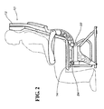
- Figure 2 is a general side view of the passenger seats of Figures 1 and 22 in an upright position.
- Figure 3 is a general side view of the passenger seats of Figures 1 and 22 in a reclining position.
- Figure 4 is a general side view of the passenger seats of Figures 1 and 22 in an sleeper position.
- Figure 5 is a partial perspective view of the passenger seat of Figure 1 in an upright position.
- Figure 6 is a partial perspective view of the passenger seat of Figure 1 in a reclining position.
- Figure 7 is a partial perspective view of the passenger seat of Figure 1 in a sleeper position.
- Figure 8 is a perspective view of one embodiment of a control panel for the passenger seat of Figure 1 .
- Figure 9 is a perspective view of an alternative embodiment of a control panel for the passenger seat of Figure 1 .
- Figure 10 is a perspective view of another alternative embodiment of a control panel for the passenger seat of Figure 1 .
- Figure 11 is a perspective view of another alternative embodiment of a control panel for the passenger seat of Figure 1 .
- Figure 12 is a perspective view of another alternative embodiment of a control panel for the passenger seat of Figure 1 .
- Figure 13 is a partial perspective view of a conventional track for a passenger seat, where the passenger seat is in an upright position.
- Figure 14 is a partial perspective view of an embodiment of a track for the passenger seat of Figure 1 , where the passenger seat is in an upright position.
- Figure 15 is a partial perspective view of the track of Figure 14 , where the passenger seat is in a reclining position.
- Figure 16 is a partial perspective view of the track of Figure 14 , where the passenger seat is in an upright position and a sleeper selection control is activated.
- Figure 17 is a partial perspective view of the track of Figure 14 , where the passenger seat is transitioning to a sleeper position.
- Figure 18 is a partial perspective view of the track of Figure 14 , where the passenger seat is in a sleeper position.
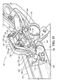
- Figure 19 is partial perspective view of an alternative embodiment of a track for the passenger seat of Figure 1 , where the passenger seat is in an upright position.
- Figure 20 is a partial perspective view of the track of Figure 19 , where the passenger seat is in an upright position and a sleeper selection control is activated.
- Figure 21 is a partial perspective view of the track of Figure 19 , where the passenger seat is in a sleeper position.
- Figure 22 is a perspective view of a passenger seat according to another embodiment of the present invention.
- Figure 23 is a partial perspective view of the passenger seat of Figure 22 in an upright position.
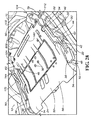
- Figure 24 is a partial perspective view of the passenger seat of Figure 22 in a reclining position.
- Figure 25 is a partial perspective view of the passenger seat of Figure 22 in a sleeper position.
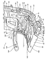
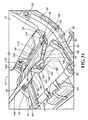
- Figure 26 is a partial perspective view of one embodiment of a track for the passenger seat of Figure 22 , where the passenger seat is in a reclining position.
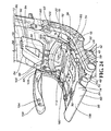
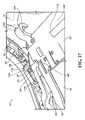
- Figure 27 is a partial perspective view of the track of Figure 26 , where the passenger seat is in an upright position.
- Figure 28 is a partial perspective view of the passenger seat of Figure 22 in an upright position.
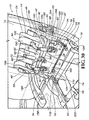
- Figure 29 is a partial perspective view of the passenger seat of Figure 22 , wherein the seat pan assembly is in a partially open position.
- Figure 30 is a partial perspective view of the passenger seat of Figure 22 , wherein the seat pan assembly is in an open position.
- Figure 31 is a partial perspective view of a passenger seat according to yet another embodiment of the present invention.
- Embodiments of the invention provide passenger seats with reclining and sleeper positions. While the passenger seats are discussed for use with aircraft, they are by no means so limited. Rather, embodiments of the passenger seats may be used with any type of vehicle or otherwise as desired.
- Figures 1-31 illustrate embodiments of a passenger seat 10.
- the passenger seat 10 comprises a seat back 12, a seat pan assembly 14, and a lumbar mechanism 18.
- the seat back 12 may be formed of materials including but not limited to aluminum, stainless steel, other metallic materials, composite materials, or other similar materials. Each side of the seat back 12 is pivotally coupled to a seat frame 20 via a pivot shaft 22.
- the seat pan assembly 14 comprises a seat pan 24, wherein the seat pan 24 has a integral design that incorporates the structural elements of a pan frame into the seat pan 24 structure.
- the seat pan assembly 14 comprises a seat pan 24 coupled to a pan frame 26.
- the seat pan assembly 14 may be formed of materials including but not limited to aluminum, stainless steel, other metallic materials, composite materials, or other similar materials. Further, in the embodiments shown in Figures 22-31 , the seat pan 24 and the pan frame 26 may be formed of the same or different materials.
- the pan frame 26 may comprise a support bar 28, two side bars 30, and at least one pivot bar 32.
- the support bar 28 and the two side bars 30 are integrally formed and serve as the primary structure of the pan frame 26.
- the support bar 28 and the two side bars 30 have an "I" formation, but any suitable shape or coupling between the support bar 28 and the two side bars 30 may be used that will provide sufficient stability and strength for the pan frame 26.
- the pivot bar 32 is coupled to an aft end 34 of the side bar 30.
- the seat pan 24 is pivotally coupled to the pan frame 26 via a sleeper pivot bar 40.
- the sleeper pivot bar 40 passes through an aperture 42 formed in the forward region of the seat pan 24 and couples to forward ends 44 of the two side bars 30.
- the seat pan 24 may include a cut-out region 46 that surrounds the pivot bar 32, but the seat pan 24 is not directly coupled to the pivot bar 32.
- the seat pan assembly 14 may also include at least one coupling device 48 that is positioned adjacent a forward end 50 of the seat pan assembly 14.
- At least one coupling receptacle 52 may be positioned adjacent a forward base frame tube 54 of a seat frame 20.
- the seat pan assembly 14 is releasably coupled to the forward base frame tube 54 by releasably engaging the coupling device 48 with the coupling receptacle 52.
- the coupling device 48 is positioned on an inner surface 56 of the seat pan 24.
- the coupling device 48 is positioned on a projection 58 that extends from the forward end 44 of the side bar 30 so that the projection 58 is positioned adjacent a side 168 of the seat pan 24.
- any suitable releasable or fixed couplings may be used to secure the seat pan assembly 14 to the seat frame 20.
- At least one reclining mechanism 60 may be coupled to the seat pan assembly 14.
- the reclining mechanism 60 may be a locking gas spring comprising a cylinder 62 and a piston 64. In other embodiments, other suitable types of reclining mechanisms may be used.
- the piston 64 is coupled to a bracket 66, which is in turn coupled to the inner surface 56 of the seat pan 24.
- the bracket 66 is secured to the seat pan 24 via fasteners 36.
- the piston 64 is coupled to a bracket 66, which is in turn coupled to an underside 68 of the support bar 28.
- the bracket 66 is coupled to the support bar 28 via the fasteners 36, but the seat pan 24 is configured to allow the fasteners 36 to pass through the seat pan 24 without directly coupling the seat pan 24 to the support bar 28 in that particular location.
- a spherical plane bearing 70 may be used to couple the piston 64 to the bracket 66.
- the spherical plane bearing 70 allows the piston 64 to rotate in all directions relative to the bracket 66, but prevents the piston 64 from sliding forward or aft relative to the bracket 66.
- any suitable type of couplings may be used to couple the piston 64 to the bracket 66.
- the cylinder 62 may include a pivotal coupling 72.
- the pivotal coupling 72 is coupled to a bracket 74 that is positioned on the forward base frame tube 54 of the seat frame 20.
- a quick release pin mechanism may be used to couple the cylinder 62 to the bracket 74.
- any suitable mechanical fasteners may be used including but not limited to screws, bolts, rivets, or other suitable mechanical fastening devices.
- the seat pan assembly 14 is pivotally linked to the seat back 12, as shown in Figures 1 , 22-25, and 28-30 .
- a pair of arms 78 are coupled to a lower end 80 of the seat back 12 and extend downward to pivotally link to a second pair of arms 82.
- the arms 82 are in turn pivotally coupled to the aft ends 34 of the two side bars 30 adjacent each pivot bar 32.
- the seat back 12 is pivotally linked to the seat pan assembly 14, but the seat back 12 does not support the seat pan assembly 14.
- the arms 82 are rigidly coupled to the aft ends 34 of the two side bars 30 adjacent each pivot bar 32.
- an aft end 160 of the seat pan assembly 14 is not separately coupled to the seat frame 20.
- the seat back 12 is pivotally coupled to the aft end 160 of the seat pan assembly 14 and provides the structural support for the aft end 160 of the seat pan assembly 14.
- the seat back 12 may be pivotally coupled to a pair of arches 104 that couple the lumbar mechanism 18 to the seat pan assembly 14.
- a torsion bar 76 may be positioned adjacent the coupling locations between the arms 78 and the arms 82, where the torsion bar 76 may provide additional torsional rigidity to the system.
- the torsion bar 76 may provide additional torsional rigidity to the system.
- any suitable arrangement that allows the seat pan assembly 14 to pivotally couple to the seat back 12 in a manner that provides sufficient torsional rigidity to the passenger seat 10 may be used.
- the lumbar mechanism 18 is coupled to the seat back 12 and the seat pan 24.
- the lumbar mechanism 18 comprises an upper structure 86, a connector 88, and a lower structure 90.
- the lumbar mechanism 18 may be formed of materials including but not limited to aluminum, stainless steel, other metallic materials, composite materials, or other similar materials.
- the upper structure 86 has a substantially trapezoidal shape that is configured to generally conform to the shape of a passenger's lumbar region.
- any suitable size and shape of the upper structure 86 may be used to provide support for a passenger's back.
- the upper structure 86 may include an aperture 92 to reduce the weight of the lumbar mechanism 18 or for other purposes.
- the upper structure 86 may also include flared sides 94 that may be angled in a forward direction to provide a curvature to the upper structure 86.
- An upper edge 96 of the upper structure 86 is pivotally coupled to the seat back 12. The particular coupling location along the seat back 12 may vary depending on the size and configuration of the upper structure 86.
- a lower edge 98 of the upper structure 86 is pivotally coupled to an upper edge 100 of the connector 88.
- the connector 88 comprises tracks 202 that are slidingly coupled to the lower structure 90, where the connector 88 is configured to allow the lower structure 90 to transition vertically relative to the upper structure 86.
- the lower structure 90 has an arched shape comprising lower legs 102 that are configured to couple to the pan frame 26.
- the lower legs 102 are pivotally coupled to the pair of arches 104 that are configured to pass over the torsion bar 76, so that the lower structure 90 is not coupled to the torsion bar 76, but also does not interfere with the operation or configuration of the coupling between the seat back 12 and the seat pan assembly 14.
- the lower legs 102 may be pivotally coupled directly to the pan frame 26 or the seat pan 24.
- the arches 104 form part of a coupling structure 106 and are rigidly coupled to a support bar 110.
- the coupling structure 106 may further comprise a pair of arms 108 that extend in a forward direction from the support bar 110.
- the arms 108 are configured to rigidly couple to an aft end 112 of the seat pan 24.
- the arches 104 are coupled directly to the aft end 112 of the seat pan 24 without a coupling structure 106, support bar 110, or arms 108.
- any suitable coupling arrangement may be used between the upper structure 86, the lower structure 90, and the seat pan assembly 14 that will allow the lumbar mechanism 18 to provide the desired support in the various positions of the passenger seat 10.
- At least one track 16 is coupled to the seat frame 20 and is configured to receive the pivot bar 32 and provide structural support for the seat pan assembly 14.
- the track 16 includes the reclining path 116 and a sleeper path 118.
- the track 16 may also include a hook 120 on a forward side 122.
- the pivot bar 32 is directed into a particular path via a diverter 124, where the diverter 124 is configured to rotate between a position substantially blocking an opening to the reclining path 116, also known as a diverter vertical position 154 (as shown in Figures 16 , 17 , 20 , and 21 ) and a position substantially blocking an opening to the sleeper path 118, also known as a diverter horizontal position 156 (as shown in Figures 14 , 15 , 18 , and 19 ).
- a diverter vertical position 154 as shown in Figures 16 , 17 , 20 , and 21
- a position substantially blocking an opening to the sleeper path 118 also known as a diverter horizontal position 156 (as shown in Figures 14 , 15 , 18 , and 19 ).
- a first arm 126 is coupled at one end to the diverter 124 and extends in a direction generally opposing the diverter 124.
- the diverter 124 and the first arm 126 are pivotally coupled to the track 16 via a fastener 128.
- the fastener 128 may be any suitable mechanical fastener including but not limited to screws, bolts, rivets, or other suitable mechanical fastening devices.
- a torsion spring 130 is also coupled to an end of the fastener 128.
- the first arm 126 is pivotally coupled at an opposing end to a second arm 132 adjacent an extension 134.
- the torsion spring 130 may be coupled to the extension 134.
- the second arm 132 is coupled to a lever 136.
- the lever 136 also includes a hook 138 and a cable receptacle 140.
- the cable receptacle 140 is slidingly coupled to a cable 142.
- a passenger desires to transition the passenger seat 10 to a sleeper position (as shown in Figures 4 and 7 )
- the passenger seat 10 is placed in an upright position (as shown in Figures 1 , 2 , and 5 ) where the pivot bar 32 is located in an aft-most position 144 on the track 16 (as shown in Figure 14 ).
- the passenger then actuates a sleeper selection control 146 to retract the cable 142, which causes the lever 136 to rotate in an aft direction (as shown in Figure 16 ).
- the sleeper selection control 146 may include a knob (as shown in Figure 8 ), a lever (as shown in Figure 9 ), a side lever (as shown in Figure 10 ), a slide (as shown in Figure 11 ), a latch (as shown in Figure 12 ), a button similar to a reclining mechanism control 158 (as shown in Figure 1 ), or other similar control devices.
- the aft-rotation of the lever 136 causes the hook 138 to also rotate in an aft direction until the hook 138 contacts and mates with the hook 120 on the track 16. Simultaneously, the rotation of the lever 136 causes a lower end 148 of the second arm 132 to rotate in an aft-direction, in turn causing an upper end 150 of the second arm 132 to rotate in a forward direction. Because the upper end 150 of the second arm 132 is pivotally coupled to the first arm 126, the rotation of the upper end 150 of the second arm 132 causes the first arm 126 to rotate upward in the aft direction until the first arm 126 is oriented in a substantially vertical position 152.
- the upward/aft rotation of the first arm 126 induces a downward/forward rotation of the diverter 124 until the diverter 124 reaches the diverter vertical position 154, which substantially blocks the opening to the reclining path 116, as shown in Figure 16 .
- the torsion spring 130 exerts a force on the first arm 126.
- the mating between the hooks 120, 138 prevents the first arm 126 from rotating back to a substantially horizontal position 114 and, thus, maintains the diverter 124 in the diverter vertical position 154.
- the passenger actuates a reclining mechanism control 158 that causes the reclining mechanism 60 to transition the seat pan assembly 14 into the sleeper position (as shown in Figures 4 and 7 ).
- the reclining mechanism 60 exerts a force on the seat pan assembly 14, which adjusts a forward position of the seat pan assembly 14 and a rotated position of the aft end 160 of the seat pan assembly 14 as the pivot bar 32 slides along the sleeper path 118.
- the pivot bar 32 reaches an upper end 162 of the sleeper path 118 (as shown in Figure 18 ), the pivot bar 32 is retained in that position via a recess 164 at the top of the sleeper path 118 and the reclining mechanism 60.
- the coupling between the seat pan assembly 14 and the seat back 12 causes the seat back 12 to pivot to the reclining position, and the coupling between the seat back 12, the seat pan 24, and the lumbar mechanism 18 causes the lower edge 98 of the upper structure 86 to rotate forward and the lower structure 90 to slide upward on the tracks 202 to compensate for the amount of forward and upward travel of the seat pan assembly 14 and recline of the seat back 12, so that the lumbar mechanism 18 is deployed in the sleeper position (as shown in Figures 4 and 7 ).
- the passenger also has the option of adjusting the amount of tilt so that the passenger seat 10 may be positioned in any configuration between the fully upright position and the sleeper position.
- the release mechanism is at least one projection 166 that is positioned on the side 168 of the seat pan 24 and travels upward until the projection 166 contacts an underside 170 of the hook 138, causing the hook 138 to disengage from the hook 120.
- the force applied by the torsion spring 130 to the first arm 126 causes the lever 136 to rotate back to its original position and the diverter 124 to rotate back to the diverter horizontal position 156, as shown in Figure 18 .
- the diverter 124 is positioned below the pivot bar 32 and substantially blocks the opening to the sleeper path 118 (as shown in Figure 18 ). The disengagement of the hooks 120, 138 also resets the sleeper selection control 146.
- any suitable mechanism may be used to rotate the diverter 124 between the diverter horizontal position 156 and the diverter vertical position 154 and transition the pivot bar 32 between the reclining path 116 and the sleeper path 118.
- a push-pull cable arrangement may be used.
- the cable 142 is pulled to rotate the diverter 124 into the diverter vertical position 154 as described above.
- the cable 142 is pushed against the lever 136, as shown in Figure 21 .
- This embodiment also may include a kicker 174 that is pivotally coupled to an outer surface 176 of the track 16.
- the kicker 174 rests against the extension 134 so that the kicker 174 pivots upward when the first arm 126 rotates upward in the aft direction.
- the kicker 174 includes a projection 178 that contacts the underside 170 of the hook 138 when the first arm 126 reaches the substantially vertical position 152. In this position, the kicker 174 also partially blocks the upper end 162 of the sleeper path 118. Thus, when the pivot bar 32 reaches the upper end 162 of the sleeper path 118, the kicker 174 is pivoted upward an additional amount, which in turn causes the projection 178 to press against the hook 138 to disengage the hooks 120, 138.
- the passenger actuates the reclining mechanism control 158 that causes the reclining mechanism 60 to transition the passenger seat 10 from the sleeper position (as shown in Figures 4 and 7 ) where the pivot bar 32 is located in the upper end 162 of the sleeper path 118 (as shown in Figures 18 and 21 ) to the fully-upright position (as shown in Figures 1 , 2 , and 5 ) where the pivot bar 32 is located in the aft-most position 144 on the reclining path 116 (as shown in Figures 14 and 19 ).
- the pivot bar 32 presses against the diverter 124 to transition it back to the diverter vertical position 154.
- a passenger actuates the reclining mechanism control 158 that causes the reclining mechanism 60 to transition the passenger seat 10 from the fully-upright position (as shown in Figures 1 , 2 , and 5 ) where the pivot bar 32 is located in the aft-most position 144 on the reclining path 116 (as shown in Figures 14 and 19 ) to the reclining position (as shown in Figures 3 and 6 ) where the pivot bar 32 is located in a forward-most position 172 on the reclining path 116 (as shown in Figure 15 ).
- the reclining mechanism 60 exerts a force on the seat pan assembly 14, which adjusts the forward position of the seat pan assembly 14 as the pivot bar 32 slides along the reclining path 116 and pivots the seat back 12 to the reclining position through the couplings between these components.
- the coupling between the seat back 12, the seat pan 24, and the lumbar mechanism 18 causes the lower structure 90 to slide downward on the tracks 202 to compensate for the amount of forward travel of the seat pan assembly 14 and recline of the seat back 12, but does not rotate the lower edge 98 of the upper structure 86 forward, so that the lumbar mechanism 18 is not deployed in the reclining position (as shown in Figures 3 and 6 ).
- the passenger also has the option of adjusting the amount of recline so that the passenger seat 10 may be positioned in any configuration between the fully upright position and the reclining position.
- the tilting mechanism 180 is separated from the reclining mechanism 60 so that a passenger may operate the sleeper and reclining functions simultaneously or separately.
- the track 16 comprises a conventional reclining path 116 without the additional sleeper path 118, similar to the embodiment shown in Figure 13 .
- the seat pan 24 is configured to pivot relative to the pan frame 26 via the sleeper pivot bar 40 and at least one tilting mechanism 180.
- the tilting mechanism 180 may be a locking gas spring comprising a cylinder 182 and a piston 184. In other embodiments, other suitable types of tilting mechanisms may be used.
- the tilting mechanism 180 may comprises at least one damper.
- the piston 184 is coupled to a bracket 186, which is in turn coupled to the underside 68 of the support bar 28.
- a spherical plane bearing 188 may be used to used to couple the piston 184 to the bracket 186.
- the spherical plane bearing 188 allows the piston 184 to rotate in all directions relative to the bracket 186, but prevents the piston 184 from sliding forward or aft relative to the bracket 186.
- any suitable type of couplings may be used to couple the piston 184 to the bracket 186.
- the cylinder 182 may include a pivotal coupling 190.
- the pivotal coupling 190 is coupled to an angled bracket 192 that is positioned on the inner surface 56 of the seat pan 24.
- a quick release pin mechanism may be used to couple the cylinder 182 to the angled bracket 192.
- any suitable mechanical fasteners may be used including but not limited to screws, bolts, rivets, or other suitable mechanical fastening devices.
- a passenger actuates the reclining mechanism control 158 that causes the reclining mechanism 60 to transition the passenger seat 10 from the fully-upright position (as shown in Figures 2 and 22 ) where the pivot bar 32 is located in the aft-most position 144 on the reclining path 116 (as shown in Figure 27 ) to the reclining position (as shown in Figure 24 ) where the pivot bar 32 is located in the forward-most position 172 on the reclining path 116 (as shown in Figure 26 ).
- the reclining mechanism 60 exerts a force on the seat pan assembly 14, which adjusts a forward position of the seat pan assembly 14 and pivots the seat back 12 to the reclining position through the couplings between these components.
- the coupling between the seat back 12, the seat pan 24, and the lumbar mechanism 18 cause the lower structure 90 to slide downward on the tracks 202 to compensate for the amount of forward travel of the seat pan assembly 14 and recline of the seat back 12, but does not rotate the lower edge 98 of the upper structure 86 forward, so that the lumbar mechanism 18 is not deployed in the reclining position (as shown in Figures 3 and 24 ).
- the passenger also has the option of adjusting the amount of recline so that the passenger seat 10 may be positioned in any configuration between the fully upright position and the reclining position.
- a passenger actuates a separate tilting mechanism control 194 that causes the tilting mechanism 180 to transition the passenger seat 10 from a substantially horizontal position where the seat pan 24 is adjacent the pan frame 26 (as shown in Figures 2 , 3 , and 22-24 ) to the sleeper position where the seat pan 24 is pivoted relative to the pan frame 26 (as shown in Figures 4 and 25 ).
- the tilting mechanism 180 causes a forward end 196 of the seat pan 24 to rotate in a downward direction, which induces an upward rotation of the aft end 112 of the seat pan 24, which is located aft of the sleeper pivot bar 40.
- the coupling between the seat back 12, the seat pan 24, and the lumbar mechanism 18 causes the lower edge 98 of the upper structure 86 to rotate forward and the lower structure 90 to slide upward on the tracks 202 to compensate for the amount of forward and upward travel of the seat pan 24 and recline of the seat back 12, so that the lumbar mechanism 18 is deployed in the sleeper position (as shown in Figures 4 and 25 ).
- the passenger also has the option of adjusting the amount of tilt so that the passenger seat 10 may be positioned in any configuration between the fully upright position and the reclining position.
- the seat pan assembly 14 is not coupled to the seat frame 20 via a pivot bar 32 and the at least one track 16. Rather, the forward end 50 of the seat pan assembly 14 is coupled to the seat frame 20 via the at least one coupling device 48 and the at least one coupling receptacle 52, but the aft end 160 of the seat pan assembly 14 is pivotally coupled to and supported by the seat back 12.
- the tilting mechanism 180 is substantially similar to the above description with respect to the embodiments shown in Figures 22-30 .
- the reclining mechanism 60 no longer comprises the pivot bar 32 or the track 16.
- a passenger actuates the reclining mechanism control 158 that causes the reclining mechanism 60 to transition the passenger seat 10 from the fully-upright position (similar to the position shown in Figure 2 ) to the reclining position (similar to the position shown in Figure 3 ).
- the aft position of the seat pan assembly 14 is controlled through the actuation of the reclining mechanism 60 and the pivotal coupling between the seat pan assembly 14 and the seat back 12.
- the reclining mechanism 60 exerts a force on the seat pan assembly 14, which adjusts a forward position of the seat pan assembly 14 and pivots the seat back 12 to the reclining position through the pivotal couplings between these components.
- the coupling between the seat back 12, the seat pan 24, and the lumbar mechanism 18 causes the lower structure 90 to slide downward on the tracks 202 to compensate for the forward travel of the seat pan assembly 14 and recline of the seat back 12, but does not rotate the lower edge 98 of the upper structure 86 forward, so that the lumbar mechanism 18 is not deployed in the reclining position.
- the passenger also has the option of adjusting the amount of recline so that the seat back 12 and the seat pan assembly 14 are positioned anywhere between the fully-upright position and the reclining position.
- any suitable device may be used to adjust the passenger seat 10 into the desired upright, reclining, and sleeper positions, including but not limited to any type of motor, spring, hydraulic controls, inflatable devices, or other similar devices, and with or without any type of lumbar mechanism 18, including but not limited to inflatable, expandable, or rotatable lumbar mechanisms.
- an IFE display 198 may be included with the passenger seat 10.
- An IFE box 200 may be attached to the seat frame 20 below the seat pan assembly 14 to provide the passenger more leg room and baggage space underneath the seat.
- a technician needs to position the seat pan assembly 14 in the open position (as shown in Figures 29-31 ).
- the technician disengages the coupling device 48 from the coupling receptacle 52.
- the technician disengages each coupling device 48 from each coupling receptacle 52.
- the technician also pulls the quick release pin (or otherwise removes the fasteners) to disconnect the reclining mechanism 60 from the seat frame 20.
- the lower structure 90 slides out of the tracks 202 when the seat pan assembly 14 is rotated into the open position.
- the lower structure 90 may optionally remain in the lower end of the tracks 202 when the seat pan assembly 14 is rotated into the open position because the seat pan 24 is pivotally coupled to the seat back 12 and pivots relative to the pan frame 26 in the same location. The technician is then able to rotate the seat pan assembly 14 upward to the open position (as shown in Figures 29-31 ) and easily access the IFE box 200.
Landscapes
- Engineering & Computer Science (AREA)
- Aviation & Aerospace Engineering (AREA)
- Transportation (AREA)
- Mechanical Engineering (AREA)
- Chairs For Special Purposes, Such As Reclining Chairs (AREA)
- Seats For Vehicles (AREA)
Claims (17)
- Siège de passager (10) comprenant :(a) un ensemble d'assise de siège (14) comprenant une assise de siège (24) mobile entre au moins des première et seconde positions ;(b) un dossier de siège (12) couplé de manière pivotante à une extrémité arrière (112) de l'ensemble d'assise de siège (14) et mobile entre au moins des première et seconde positions ; et(c) un mécanisme lombaire (18) couplé au dossier de siège (12) et à l'ensemble d'assise de siège (14) et mobile entre au moins des première et seconde positions,(d) un châssis de siège (20) comprenant au moins un rail (16), ledit au moins un rail (16) comprend une trajectoire de passage en position inclinée (116) et une trajectoire de passage en position couchette (118), caractérisé en ce que :un dispositif de déviation (124) est couplé au au moins un rail (16) et configuré pour tourner entre une position bloquant sensiblement une ouverture de la trajectoire de passage en position inclinée (116) et une position bloquant sensiblement une ouverture de la trajectoire de passage en position couchette (118).
- Siège de passager (10) selon la revendication 1, dans lequel l'assise de siège (24) est mobile entre au moins des première et seconde positions avant et au moins des première et seconde positions de pivotement.
- Siège de passager (10) selon la revendication 1 ou 2, dans lequel l'ensemble d'assise de siège (14) comprend un mécanisme d'inclinaison (60), le mécanisme d'inclinaison (60) est configuré pour :(a) régler une position avant de l'ensemble d'assise de siège (14) ; et(b) faire pivoter le dossier de siège (12) entre des positions droite et inclinée.
- Siège de passager (10) selon l'une quelconque des revendications 1 à 3, dans lequel l'ensemble d'assise de siège (14) comprend un mécanisme d'inclinaison (180), ledit mécanisme d'inclinaison (180) est configuré pour :(a) faire pivoter une extrémité arrière d'une assise de siège (12) par rapport à un châssis d'assise (26) ; et(b) faire pivoter le mécanisme lombaire (18) par rapport au dossier de siège (12).
- Siège de passager (10) selon l'une quelconque des revendications précédentes, dans lequel au moins une barre de pivot (32) est couplée à l'extrémité arrière de l'ensemble d'assise de siège (14) et est configurée pour se coupler de manière coulissante au au moins un rail (16).
- Siège de passager (10) selon l'une quelconque des revendications précédentes, comprenant en outre une commande de sélection de couchette (146) qui est configurée pour faire pivoter le dispositif de déviation dans la position bloquant sensiblement l'ouverture de la trajectoire de passage en position inclinée (116).
- Siège de passager (10) selon la revendication 6, dans lequel la commande de sélection de couchette (146) est un bouton, un poussoir, un levier latéral, un levier, une glissière ou un verrou.
- Siège de passager (10) selon l'une quelconque des revendications précédentes, comprenant en outre un mécanisme de déblocage qui est configuré pour faire pivoter le dispositif de déviation (124) dans la position bloquant sensiblement l'ouverture de la trajectoire de passage en position couchette (118).
- Siège de passager (10) selon l'une quelconque des revendications 3 à 8, dans lequel le mécanisme d'inclinaison (60) est configuré pour :(a) ajuster une position avant de l'ensemble d'assise de siège (14) lorsque la trajectoire de passage en position inclinée (116) est ouverte ;(b) ajuster la position avant de l'ensemble d'assise de siège (114), une position de pivotement de l'extrémité arrière de l'ensemble d'assise de siège (114), et faire pivoter le mécanisme lombaire (18) par rapport au dossier de siège (12) lorsque la trajectoire de passage en position couchette (118) est ouverte ; et(c) faire pivoter le dossier de siège (12) entre des positions droite et inclinée.
- Siège de passager (10) selon l'une quelconque des revendications 4 à 9, dans lequel le mécanisme d'inclinaison (180) est configuré pour faire pivoter le mécanisme lombaire (18) par rapport au dossier de siège (12).
- Procédé pour positionner un siège de passager (10), dans lequel le siège de passager (10) comprend (i) un ensemble d'assise de siège (14), (ii) un dossier de siège (12) couplé de manière pivotante à une extrémité arrière de l'ensemble d'assise de siège (14), et (iii) un châssis de siège (20) comprenant au moins un rail (16) ayant une trajectoire de passage en position inclinée (116) et une trajectoire de passage en position couchette (118), le procédé comprenant les étapes consistant à :(a) actionner une commande de sélection de couchette (146) pour sélectionner la trajectoire de passage en position couchette (118) ; et(b) actionner le mécanisme d'inclinaison (60) pour faire passer le siège de passager (10) dans une position de couchette,dans lequel l'étape consistant à actionner la commande de sélection de couchette (146) fait pivoter un dispositif de déviation (124) dans une position bloquant sensiblement une ouverture de la trajectoire de passage en position inclinée (116).
- Procédé selon la revendication 11, comprenant en outre l'étape consistant à actionner un mécanisme de déblocage qui fait pivoter le dispositif de déviation (124) dans une position bloquant sensiblement une ouverture de la trajectoire de passage en position couchette (118).
- Procédé selon la revendication 11 ou 12, comprenant en outre l'étape consistant à actionner le mécanisme d'inclinaison (60) pour faire passer le siège de passager (10) dans une position inclinée.
- Procédé selon l'une quelconque des revendications 11 à 13, comprenant en outre un mécanisme lombaire couplé au dossier de siège et à l'ensemble d'assise de siège, dans lequel l'étape consistant à actionner le mécanisme d'inclinaison (60) fait pivoter le mécanisme lombaire (18) vers l'avant.
- Procédé pour positionner un siège de passager (10) selon l'une quelconque des revendications 1 à 10, le procédé comprenant les étapes consistant à :(a) actionner le mécanisme d'inclinaison (180) pour faire passer le siège de passager (10) dans une position de couchette ; et(b) actionner un mécanisme d'inclinaison (60) pour faire passer le siège de passager (10) dans une position inclinée.
- Procédé selon la revendication 15, dans lequel l'étape consistant à actionner le mécanisme d'inclinaison (180) fait pivoter le mécanisme lombaire (18) vers l'avant.
- Siège de passager (10) comprenant :(a) un ensemble d'assise de siège (14), ledit ensemble d'assise de siège (14) comprend une assise de siège (24) mobile entre au moins des première et seconde positions ;(b) un dossier de siège (12) couplé de manière pivotante à une extrémité arrière de l'ensemble d'assise de siège (14) et mobile entre au moins des première et seconde positions ; et(c) un châssis de siège (20) comprenant au moins un rail (16) ayant une trajectoire de passage en position inclinée (116) et une trajectoire de passage en position couchette (118), dans lequel un dispositif de déviation (124) est couplé au au moins un rail (16) et configuré pour pivoter entre une position bloquant sensiblement une ouverture de la trajectoire de passage en position inclinée (116) et une position bloquant sensiblement une ouverture de la trajectoire de passage en position couchette (118).
Applications Claiming Priority (4)
| Application Number | Priority Date | Filing Date | Title |
|---|---|---|---|
| US30299410P | 2010-02-10 | 2010-02-10 | |
| US40332610P | 2010-09-14 | 2010-09-14 | |
| US45897910P | 2010-12-03 | 2010-12-03 | |
| PCT/US2011/024407 WO2011100476A1 (fr) | 2010-02-10 | 2011-02-10 | Siège de passager |
Publications (2)
| Publication Number | Publication Date |
|---|---|
| EP2534049A1 EP2534049A1 (fr) | 2012-12-19 |
| EP2534049B1 true EP2534049B1 (fr) | 2013-11-20 |
Family
ID=43923769
Family Applications (1)
| Application Number | Title | Priority Date | Filing Date |
|---|---|---|---|
| EP11705121.9A Active EP2534049B1 (fr) | 2010-02-10 | 2011-02-10 | Siege de passager |
Country Status (4)
| Country | Link |
|---|---|
| US (1) | US8439435B2 (fr) |
| EP (1) | EP2534049B1 (fr) |
| CA (1) | CA2789272A1 (fr) |
| WO (1) | WO2011100476A1 (fr) |
Families Citing this family (28)
| Publication number | Priority date | Publication date | Assignee | Title |
|---|---|---|---|---|
| DE102009050903B4 (de) * | 2009-10-27 | 2014-02-13 | Siemens Aktiengesellschaft | Fahrzeugsitz |
| US8827365B2 (en) | 2010-02-10 | 2014-09-09 | Zodiac Seats Us Llc | Passenger seat |
| EP2534049B1 (fr) | 2010-02-10 | 2013-11-20 | Zodiac Seats US LLC | Siege de passager |
| US8596719B2 (en) | 2010-10-01 | 2013-12-03 | Permobil Ab | Wheelchair backrest assembly |
| EP2729365B1 (fr) | 2011-07-06 | 2016-11-30 | Zodiac Seats US LLC | Ensemble plateau de siège |
| US20130093218A1 (en) * | 2011-10-14 | 2013-04-18 | Lear Corporation | Seat Assembly Having a Folding Seat Bottom and Head Restraint |
| US9180793B2 (en) | 2011-12-20 | 2015-11-10 | Franklin Products, Inc. | Movable seating arrangement |
| US20140159451A1 (en) * | 2012-12-06 | 2014-06-12 | Lear Corporation | Vehicle seat assembly and method |
| WO2014163581A1 (fr) * | 2013-04-05 | 2014-10-09 | Singapore Technologies Aerospace Ltd | Structure de siège pour un siège passager, et siège passager |
| EP2981190B1 (fr) * | 2013-04-05 | 2021-11-17 | St Engineering Aerospace Ltd. | Siège de passager pour un avion |
| DE102013005859A1 (de) * | 2013-04-08 | 2014-10-09 | Zim Flugsitz Gmbh | "Fluggastsitz mit einem Gestell" |
| EP2805848B1 (fr) * | 2013-05-22 | 2018-09-26 | Fabricacion Asientos Vehiculos Industriales, S.A. | Siège pour véhicules |
| US9994321B2 (en) * | 2014-04-03 | 2018-06-12 | Zodiac Seats Us Llc | Reclining passenger seat |
| GB2539913B (en) * | 2015-06-30 | 2019-10-02 | British Airways Plc | Aircraft passenger seat mechanism |
| US10696191B2 (en) * | 2015-11-03 | 2020-06-30 | Safran Seats Usa Llc | Pull actuator release for reclining seats |
| WO2017192875A1 (fr) * | 2016-05-05 | 2017-11-09 | Timco Aviation Services, Inc. | Système de siège |
| EP3538439B1 (fr) * | 2016-11-10 | 2024-03-06 | Safran Seats USA LLC | Cadre de base avec tube avec des sections transversales non circulaires |
| US10518685B2 (en) | 2017-03-08 | 2019-12-31 | Ts Tech Co., Ltd. | Conveyance seat |
| DE102017107154A1 (de) * | 2017-04-03 | 2018-10-04 | Recaro Aircraft Seating Gmbh & Co. Kg | Flugzeugsitzvorrichtung |
| CN107253459A (zh) * | 2017-06-17 | 2017-10-17 | 孟祥厚 | 车用附加随背变角背部支撑 |
| US10343558B2 (en) | 2017-10-19 | 2019-07-09 | Nio Usa, Inc. | Fixed structure seat |
| US10427793B2 (en) * | 2017-11-02 | 2019-10-01 | Rockwell Collins, Inc. | Slouching divan with damped motion |
| US10822091B2 (en) * | 2018-03-06 | 2020-11-03 | Bombardier Inc. | Passenger seat for aircraft |
| TWI667000B (zh) * | 2018-03-22 | 2019-08-01 | 漢翔航空工業股份有限公司 | 椅背連動座盤機構 |
| USD903349S1 (en) * | 2018-04-23 | 2020-12-01 | Autoflug Gmbh | Seat for means of transport |
| US11866176B2 (en) * | 2019-03-29 | 2024-01-09 | The Boeing Company | Variable reclination backrest for a seat assembly |
| US11975842B2 (en) | 2019-09-30 | 2024-05-07 | Safran Seats Usa Llc | Bottom pan torque bearing attachment |
| DE102022133443A1 (de) * | 2022-12-15 | 2024-06-20 | Grammer Aktiengesellschaft | Fahrzeugsitz zur gleichzeitigen Einstellung einer Sitztiefe und einer Lendenstütze |
Family Cites Families (28)
| Publication number | Priority date | Publication date | Assignee | Title |
|---|---|---|---|---|
| GB788410A (en) * | 1955-07-25 | 1958-01-02 | Res Interests Ltd | Improvements in or relating to reclining chairs |
| FR1352981A (fr) | 1963-01-10 | 1964-02-21 | Citroen Sa Andre | Siège réglable pour véhicule |
| BE758686A (fr) | 1969-11-25 | 1971-04-16 | Universal Oil Prod Co | Perfectionnements relatifs aux sieges de vehicules |
| DE2916897A1 (de) * | 1979-04-07 | 1980-11-06 | Otto Zapf | Sitzmoebel |
| JPH0289947U (fr) * | 1988-12-28 | 1990-07-17 | ||
| US5558399A (en) * | 1994-09-13 | 1996-09-24 | Serber; Hector | Seat and lumbar motion chair, assembly and method |
| DE69614725T2 (de) * | 1995-01-27 | 2002-07-04 | Britax Aircraft Interiors Uk Ltd., Gallows Hill | Fahrgastsitz |
| GB9617706D0 (en) * | 1996-08-22 | 1996-10-02 | Britax Rumbold Ltd | Vehicle seat |
| US20010000639A1 (en) * | 1997-02-20 | 2001-05-03 | Singapore Airlines Ltd. | Transport accommodation |
| NO313933B1 (no) * | 1999-03-01 | 2002-12-30 | Kjartan Alvestad | Reguleringsanordning for ligge- eller sittemöbel |
| IT1306152B1 (it) * | 1999-06-02 | 2001-05-30 | Aviointeriors Spa | Poltrona con movimento a culla perfezionato, in particolare peraeromobili. |
| US6237994B1 (en) * | 1999-06-11 | 2001-05-29 | Weber Aircraft, Inc. | Multi-function seats |
| EP1116653B1 (fr) | 2000-01-14 | 2006-03-15 | Be Aerospace, Inc. | Siège passager avec repose-jambes en tissu |
| FR2820400B1 (fr) * | 2001-02-05 | 2003-04-11 | Sicma Aero Seat | Siege multipositions pour avion |
| ITRM20010103A1 (it) * | 2001-02-26 | 2002-08-26 | Aviointeriors S P A | Meccanismo per ottenere la reclinazione di una poltrona, in particolare una poltrona per aeromobile. |
| US6692069B2 (en) * | 2001-07-20 | 2004-02-17 | B E Aerospace, Inc. | Aircraft sleeper seat |
| CA2581738C (fr) * | 2001-08-09 | 2009-04-14 | Virgin Atlantic Airways Limited | Systeme de sieges et unite d'accueil de passagers pour vehicule |
| US20030111888A1 (en) * | 2001-12-18 | 2003-06-19 | Brennan Edward J. | Vehicle passenger seat |
| DE10215028A1 (de) * | 2002-04-05 | 2003-10-30 | Recaro Aircraft Seating Gmbh | Sitz, insbesondere Fluggastsitz |
| US7229118B2 (en) * | 2004-10-20 | 2007-06-12 | Lear Corporation | Slouch rear seat system |
| JP2006123715A (ja) * | 2004-10-28 | 2006-05-18 | Nhk Spring Co Ltd | 車両用シート |
| GB2448835B (en) * | 2005-12-23 | 2010-12-29 | British Airways Plc | Aircraft passenger seat |
| JP5220319B2 (ja) * | 2007-01-18 | 2013-06-26 | 日本発條株式会社 | 車両用シート装置 |
| GB0704546D0 (en) * | 2007-03-08 | 2007-04-18 | Contour Premium Aircraft Seati | Adjustable seat |
| DE102007012728B4 (de) | 2007-03-16 | 2009-06-10 | Grammer Ag | Passagiersitz für Fahrzeuge, insbesondere für Bahnfahrzeuge |
| US8272694B2 (en) * | 2008-07-08 | 2012-09-25 | B/E Aerospace, Inc. | Articulating passenger seat |
| EP2534049B1 (fr) | 2010-02-10 | 2013-11-20 | Zodiac Seats US LLC | Siege de passager |
| US8827365B2 (en) * | 2010-02-10 | 2014-09-09 | Zodiac Seats Us Llc | Passenger seat |
-
2011
- 2011-02-10 EP EP11705121.9A patent/EP2534049B1/fr active Active
- 2011-02-10 WO PCT/US2011/024407 patent/WO2011100476A1/fr not_active Ceased
- 2011-02-10 CA CA2789272A patent/CA2789272A1/fr not_active Abandoned
- 2011-02-10 US US13/025,086 patent/US8439435B2/en active Active
Also Published As
| Publication number | Publication date |
|---|---|
| CA2789272A1 (fr) | 2011-08-18 |
| US8439435B2 (en) | 2013-05-14 |
| EP2534049A1 (fr) | 2012-12-19 |
| US20110193386A1 (en) | 2011-08-11 |
| WO2011100476A1 (fr) | 2011-08-18 |
Similar Documents
| Publication | Publication Date | Title |
|---|---|---|
| EP2534049B1 (fr) | Siege de passager | |
| EP2691303B1 (fr) | Siège pour passager | |
| US8733840B2 (en) | Seat pan assembly | |
| EP3060473B1 (fr) | Baquet articulé indépendamment de siège d'aéronef | |
| JP5490873B2 (ja) | 単一アクチュエータシート機構を備えた乗客シート | |
| EP3519243B1 (fr) | Ensemble de siège passager d'aéronef comprenant un appareil d'inclinaison de dossier | |
| EP2630005B1 (fr) | Siège inclinable | |
| EP2507132B1 (fr) | Ensemble de siège passager | |
| US20160325837A1 (en) | Aircraft seat | |
| US9168848B2 (en) | Vehicle seating assembly | |
| EP4101689B1 (fr) | Siège d'avion | |
| EP2790963A1 (fr) | Siège de véhicule | |
| JP2013544202A (ja) | スライド式ベッドポッド | |
| EP2718184B1 (fr) | Ensemble siège de passager | |
| JP2013540075A (ja) | 乗客席アセンブリ及びその態様 | |
| EP1805079A2 (fr) | Unite d'hebergement de passagers en avion a couchage deployant | |
| US9061766B2 (en) | Synchronous seat recline mechanism | |
| EP3715255B1 (fr) | Siège, en particulier un siège d'aéronef | |
| EP4037971B1 (fr) | Mécanisme cinématique et d'inclinaison à intrusion nulle pour sièges d'avion commerciaux | |
| US20150008713A1 (en) | Aircraft seat | |
| EP3197712B1 (fr) | Siège d'aéronef | |
| CN118043229A (zh) | 用于运输车辆的乘客座椅 |
Legal Events
| Date | Code | Title | Description |
|---|---|---|---|
| PUAI | Public reference made under article 153(3) epc to a published international application that has entered the european phase |
Free format text: ORIGINAL CODE: 0009012 |
|
| 17P | Request for examination filed |
Effective date: 20120828 |
|
| AK | Designated contracting states |
Kind code of ref document: A1 Designated state(s): AL AT BE BG CH CY CZ DE DK EE ES FI FR GB GR HR HU IE IS IT LI LT LU LV MC MK MT NL NO PL PT RO RS SE SI SK SM TR |
|
| DAX | Request for extension of the european patent (deleted) | ||
| REG | Reference to a national code |
Ref country code: DE Ref legal event code: R079 Ref document number: 602011003875 Country of ref document: DE Free format text: PREVIOUS MAIN CLASS: B64D0011060000 Ipc: B60N0002660000 |
|
| GRAP | Despatch of communication of intention to grant a patent |
Free format text: ORIGINAL CODE: EPIDOSNIGR1 |
|
| RIC1 | Information provided on ipc code assigned before grant |
Ipc: B60N 2/24 20060101ALI20130531BHEP Ipc: B60N 2/66 20060101AFI20130531BHEP |
|
| INTG | Intention to grant announced |
Effective date: 20130619 |
|
| GRAS | Grant fee paid |
Free format text: ORIGINAL CODE: EPIDOSNIGR3 |
|
| RAP1 | Party data changed (applicant data changed or rights of an application transferred) |
Owner name: ZODIAC SEATS US LLC |
|
| GRAA | (expected) grant |
Free format text: ORIGINAL CODE: 0009210 |
|
| AK | Designated contracting states |
Kind code of ref document: B1 Designated state(s): AL AT BE BG CH CY CZ DE DK EE ES FI FR GB GR HR HU IE IS IT LI LT LU LV MC MK MT NL NO PL PT RO RS SE SI SK SM TR |
|
| REG | Reference to a national code |
Ref country code: GB Ref legal event code: FG4D |
|
| REG | Reference to a national code |
Ref country code: CH Ref legal event code: EP |
|
| REG | Reference to a national code |
Ref country code: AT Ref legal event code: REF Ref document number: 641381 Country of ref document: AT Kind code of ref document: T Effective date: 20131215 |
|
| REG | Reference to a national code |
Ref country code: IE Ref legal event code: FG4D |
|
| REG | Reference to a national code |
Ref country code: DE Ref legal event code: R096 Ref document number: 602011003875 Country of ref document: DE Effective date: 20140116 |
|
| REG | Reference to a national code |
Ref country code: NL Ref legal event code: VDEP Effective date: 20131120 |
|
| REG | Reference to a national code |
Ref country code: AT Ref legal event code: MK05 Ref document number: 641381 Country of ref document: AT Kind code of ref document: T Effective date: 20131120 |
|
| REG | Reference to a national code |
Ref country code: LT Ref legal event code: MG4D |
|
| PG25 | Lapsed in a contracting state [announced via postgrant information from national office to epo] |
Ref country code: LT Free format text: LAPSE BECAUSE OF FAILURE TO SUBMIT A TRANSLATION OF THE DESCRIPTION OR TO PAY THE FEE WITHIN THE PRESCRIBED TIME-LIMIT Effective date: 20131120 Ref country code: NL Free format text: LAPSE BECAUSE OF FAILURE TO SUBMIT A TRANSLATION OF THE DESCRIPTION OR TO PAY THE FEE WITHIN THE PRESCRIBED TIME-LIMIT Effective date: 20131120 Ref country code: NO Free format text: LAPSE BECAUSE OF FAILURE TO SUBMIT A TRANSLATION OF THE DESCRIPTION OR TO PAY THE FEE WITHIN THE PRESCRIBED TIME-LIMIT Effective date: 20140220 Ref country code: FI Free format text: LAPSE BECAUSE OF FAILURE TO SUBMIT A TRANSLATION OF THE DESCRIPTION OR TO PAY THE FEE WITHIN THE PRESCRIBED TIME-LIMIT Effective date: 20131120 Ref country code: SE Free format text: LAPSE BECAUSE OF FAILURE TO SUBMIT A TRANSLATION OF THE DESCRIPTION OR TO PAY THE FEE WITHIN THE PRESCRIBED TIME-LIMIT Effective date: 20131120 Ref country code: HR Free format text: LAPSE BECAUSE OF FAILURE TO SUBMIT A TRANSLATION OF THE DESCRIPTION OR TO PAY THE FEE WITHIN THE PRESCRIBED TIME-LIMIT Effective date: 20131120 Ref country code: IS Free format text: LAPSE BECAUSE OF FAILURE TO SUBMIT A TRANSLATION OF THE DESCRIPTION OR TO PAY THE FEE WITHIN THE PRESCRIBED TIME-LIMIT Effective date: 20140320 |
|
| PG25 | Lapsed in a contracting state [announced via postgrant information from national office to epo] |
Ref country code: ES Free format text: LAPSE BECAUSE OF FAILURE TO SUBMIT A TRANSLATION OF THE DESCRIPTION OR TO PAY THE FEE WITHIN THE PRESCRIBED TIME-LIMIT Effective date: 20131120 Ref country code: LV Free format text: LAPSE BECAUSE OF FAILURE TO SUBMIT A TRANSLATION OF THE DESCRIPTION OR TO PAY THE FEE WITHIN THE PRESCRIBED TIME-LIMIT Effective date: 20131120 Ref country code: BE Free format text: LAPSE BECAUSE OF FAILURE TO SUBMIT A TRANSLATION OF THE DESCRIPTION OR TO PAY THE FEE WITHIN THE PRESCRIBED TIME-LIMIT Effective date: 20131120 Ref country code: RS Free format text: LAPSE BECAUSE OF FAILURE TO SUBMIT A TRANSLATION OF THE DESCRIPTION OR TO PAY THE FEE WITHIN THE PRESCRIBED TIME-LIMIT Effective date: 20131120 Ref country code: AT Free format text: LAPSE BECAUSE OF FAILURE TO SUBMIT A TRANSLATION OF THE DESCRIPTION OR TO PAY THE FEE WITHIN THE PRESCRIBED TIME-LIMIT Effective date: 20131120 |
|
| PG25 | Lapsed in a contracting state [announced via postgrant information from national office to epo] |
Ref country code: PT Free format text: LAPSE BECAUSE OF FAILURE TO SUBMIT A TRANSLATION OF THE DESCRIPTION OR TO PAY THE FEE WITHIN THE PRESCRIBED TIME-LIMIT Effective date: 20140320 |
|
| PG25 | Lapsed in a contracting state [announced via postgrant information from national office to epo] |
Ref country code: EE Free format text: LAPSE BECAUSE OF FAILURE TO SUBMIT A TRANSLATION OF THE DESCRIPTION OR TO PAY THE FEE WITHIN THE PRESCRIBED TIME-LIMIT Effective date: 20131120 |
|
| REG | Reference to a national code |
Ref country code: DE Ref legal event code: R097 Ref document number: 602011003875 Country of ref document: DE |
|
| PG25 | Lapsed in a contracting state [announced via postgrant information from national office to epo] |
Ref country code: PL Free format text: LAPSE BECAUSE OF FAILURE TO SUBMIT A TRANSLATION OF THE DESCRIPTION OR TO PAY THE FEE WITHIN THE PRESCRIBED TIME-LIMIT Effective date: 20131120 Ref country code: RO Free format text: LAPSE BECAUSE OF FAILURE TO SUBMIT A TRANSLATION OF THE DESCRIPTION OR TO PAY THE FEE WITHIN THE PRESCRIBED TIME-LIMIT Effective date: 20131120 Ref country code: CZ Free format text: LAPSE BECAUSE OF FAILURE TO SUBMIT A TRANSLATION OF THE DESCRIPTION OR TO PAY THE FEE WITHIN THE PRESCRIBED TIME-LIMIT Effective date: 20131120 Ref country code: SK Free format text: LAPSE BECAUSE OF FAILURE TO SUBMIT A TRANSLATION OF THE DESCRIPTION OR TO PAY THE FEE WITHIN THE PRESCRIBED TIME-LIMIT Effective date: 20131120 |
|
| PLBE | No opposition filed within time limit |
Free format text: ORIGINAL CODE: 0009261 |
|
| STAA | Information on the status of an ep patent application or granted ep patent |
Free format text: STATUS: NO OPPOSITION FILED WITHIN TIME LIMIT |
|
| PG25 | Lapsed in a contracting state [announced via postgrant information from national office to epo] |
Ref country code: MC Free format text: LAPSE BECAUSE OF FAILURE TO SUBMIT A TRANSLATION OF THE DESCRIPTION OR TO PAY THE FEE WITHIN THE PRESCRIBED TIME-LIMIT Effective date: 20131120 Ref country code: DK Free format text: LAPSE BECAUSE OF FAILURE TO SUBMIT A TRANSLATION OF THE DESCRIPTION OR TO PAY THE FEE WITHIN THE PRESCRIBED TIME-LIMIT Effective date: 20131120 Ref country code: LU Free format text: LAPSE BECAUSE OF FAILURE TO SUBMIT A TRANSLATION OF THE DESCRIPTION OR TO PAY THE FEE WITHIN THE PRESCRIBED TIME-LIMIT Effective date: 20140210 |
|
| REG | Reference to a national code |
Ref country code: CH Ref legal event code: PL |
|
| 26N | No opposition filed |
Effective date: 20140821 |
|
| PG25 | Lapsed in a contracting state [announced via postgrant information from national office to epo] |
Ref country code: CH Free format text: LAPSE BECAUSE OF NON-PAYMENT OF DUE FEES Effective date: 20140228 Ref country code: LI Free format text: LAPSE BECAUSE OF NON-PAYMENT OF DUE FEES Effective date: 20140228 |
|
| REG | Reference to a national code |
Ref country code: IE Ref legal event code: MM4A |
|
| REG | Reference to a national code |
Ref country code: DE Ref legal event code: R097 Ref document number: 602011003875 Country of ref document: DE Effective date: 20140821 |
|
| PG25 | Lapsed in a contracting state [announced via postgrant information from national office to epo] |
Ref country code: IE Free format text: LAPSE BECAUSE OF NON-PAYMENT OF DUE FEES Effective date: 20140210 |
|
| PG25 | Lapsed in a contracting state [announced via postgrant information from national office to epo] |
Ref country code: SI Free format text: LAPSE BECAUSE OF FAILURE TO SUBMIT A TRANSLATION OF THE DESCRIPTION OR TO PAY THE FEE WITHIN THE PRESCRIBED TIME-LIMIT Effective date: 20131120 |
|
| REG | Reference to a national code |
Ref country code: FR Ref legal event code: PLFP Year of fee payment: 6 |
|
| PG25 | Lapsed in a contracting state [announced via postgrant information from national office to epo] |
Ref country code: MT Free format text: LAPSE BECAUSE OF FAILURE TO SUBMIT A TRANSLATION OF THE DESCRIPTION OR TO PAY THE FEE WITHIN THE PRESCRIBED TIME-LIMIT Effective date: 20131120 |
|
| PG25 | Lapsed in a contracting state [announced via postgrant information from national office to epo] |
Ref country code: SM Free format text: LAPSE BECAUSE OF FAILURE TO SUBMIT A TRANSLATION OF THE DESCRIPTION OR TO PAY THE FEE WITHIN THE PRESCRIBED TIME-LIMIT Effective date: 20131120 |
|
| PG25 | Lapsed in a contracting state [announced via postgrant information from national office to epo] |
Ref country code: CY Free format text: LAPSE BECAUSE OF FAILURE TO SUBMIT A TRANSLATION OF THE DESCRIPTION OR TO PAY THE FEE WITHIN THE PRESCRIBED TIME-LIMIT Effective date: 20131120 Ref country code: GR Free format text: LAPSE BECAUSE OF FAILURE TO SUBMIT A TRANSLATION OF THE DESCRIPTION OR TO PAY THE FEE WITHIN THE PRESCRIBED TIME-LIMIT Effective date: 20140221 Ref country code: BG Free format text: LAPSE BECAUSE OF FAILURE TO SUBMIT A TRANSLATION OF THE DESCRIPTION OR TO PAY THE FEE WITHIN THE PRESCRIBED TIME-LIMIT Effective date: 20131120 |
|
| PG25 | Lapsed in a contracting state [announced via postgrant information from national office to epo] |
Ref country code: HU Free format text: LAPSE BECAUSE OF FAILURE TO SUBMIT A TRANSLATION OF THE DESCRIPTION OR TO PAY THE FEE WITHIN THE PRESCRIBED TIME-LIMIT; INVALID AB INITIO Effective date: 20110210 Ref country code: TR Free format text: LAPSE BECAUSE OF FAILURE TO SUBMIT A TRANSLATION OF THE DESCRIPTION OR TO PAY THE FEE WITHIN THE PRESCRIBED TIME-LIMIT Effective date: 20131120 |
|
| REG | Reference to a national code |
Ref country code: FR Ref legal event code: PLFP Year of fee payment: 7 |
|
| REG | Reference to a national code |
Ref country code: FR Ref legal event code: PLFP Year of fee payment: 8 |
|
| PG25 | Lapsed in a contracting state [announced via postgrant information from national office to epo] |
Ref country code: MK Free format text: LAPSE BECAUSE OF FAILURE TO SUBMIT A TRANSLATION OF THE DESCRIPTION OR TO PAY THE FEE WITHIN THE PRESCRIBED TIME-LIMIT Effective date: 20131120 |
|
| PG25 | Lapsed in a contracting state [announced via postgrant information from national office to epo] |
Ref country code: AL Free format text: LAPSE BECAUSE OF FAILURE TO SUBMIT A TRANSLATION OF THE DESCRIPTION OR TO PAY THE FEE WITHIN THE PRESCRIBED TIME-LIMIT Effective date: 20131120 |
|
| PGFP | Annual fee paid to national office [announced via postgrant information from national office to epo] |
Ref country code: IT Payment date: 20190325 Year of fee payment: 17 |
|
| REG | Reference to a national code |
Ref country code: DE Ref legal event code: R082 Ref document number: 602011003875 Country of ref document: DE Representative=s name: GODEMEYER BLUM LENZE PATENTANWAELTE, PARTNERSC, DE Ref country code: DE Ref legal event code: R081 Ref document number: 602011003875 Country of ref document: DE Owner name: SAFRAN SEATS USA LLC, GAINESVILLE, US Free format text: FORMER OWNER: ZODIAC SEATS US LLC, GAINESVILLE, TEX., US |
|
| PG25 | Lapsed in a contracting state [announced via postgrant information from national office to epo] |
Ref country code: IT Free format text: LAPSE BECAUSE OF NON-PAYMENT OF DUE FEES Effective date: 20200210 |
|
| PGFP | Annual fee paid to national office [announced via postgrant information from national office to epo] |
Ref country code: DE Payment date: 20240123 Year of fee payment: 14 |
|
| PG25 | Lapsed in a contracting state [announced via postgrant information from national office to epo] |
Ref country code: IT Free format text: LAPSE BECAUSE OF NON-PAYMENT OF DUE FEES Effective date: 20200210 |
|
| PGRI | Patent reinstated in contracting state [announced from national office to epo] |
Ref country code: IT Effective date: 20240101 |
|
| REG | Reference to a national code |
Ref country code: DE Ref legal event code: R119 Ref document number: 602011003875 Country of ref document: DE |
|
| PG25 | Lapsed in a contracting state [announced via postgrant information from national office to epo] |
Ref country code: DE Free format text: LAPSE BECAUSE OF NON-PAYMENT OF DUE FEES Effective date: 20250902 |
|
| PGFP | Annual fee paid to national office [announced via postgrant information from national office to epo] |
Ref country code: GB Payment date: 20260219 Year of fee payment: 16 |
|
| PGFP | Annual fee paid to national office [announced via postgrant information from national office to epo] |
Ref country code: FR Payment date: 20260213 Year of fee payment: 16 |