EP2534066B2 - Container with scooping utensil and scooping retainer in the closure - Google Patents
Container with scooping utensil and scooping retainer in the closure Download PDFInfo
- Publication number
- EP2534066B2 EP2534066B2 EP11729532.9A EP11729532A EP2534066B2 EP 2534066 B2 EP2534066 B2 EP 2534066B2 EP 11729532 A EP11729532 A EP 11729532A EP 2534066 B2 EP2534066 B2 EP 2534066B2
- Authority
- EP
- European Patent Office
- Prior art keywords
- container
- flange
- gap
- handle
- utensil
- Prior art date
- Legal status (The legal status is an assumption and is not a legal conclusion. Google has not performed a legal analysis and makes no representation as to the accuracy of the status listed.)
- Active
Links
Images






Classifications
-
- B—PERFORMING OPERATIONS; TRANSPORTING
- B65—CONVEYING; PACKING; STORING; HANDLING THIN OR FILAMENTARY MATERIAL
- B65D—CONTAINERS FOR STORAGE OR TRANSPORT OF ARTICLES OR MATERIALS, e.g. BAGS, BARRELS, BOTTLES, BOXES, CANS, CARTONS, CRATES, DRUMS, JARS, TANKS, HOPPERS, FORWARDING CONTAINERS; ACCESSORIES, CLOSURES, OR FITTINGS THEREFOR; PACKAGING ELEMENTS; PACKAGES
- B65D83/00—Containers or packages with special means for dispensing contents
-
- B—PERFORMING OPERATIONS; TRANSPORTING
- B65—CONVEYING; PACKING; STORING; HANDLING THIN OR FILAMENTARY MATERIAL
- B65D—CONTAINERS FOR STORAGE OR TRANSPORT OF ARTICLES OR MATERIALS, e.g. BAGS, BARRELS, BOTTLES, BOXES, CANS, CARTONS, CRATES, DRUMS, JARS, TANKS, HOPPERS, FORWARDING CONTAINERS; ACCESSORIES, CLOSURES, OR FITTINGS THEREFOR; PACKAGING ELEMENTS; PACKAGES
- B65D21/00—Nestable, stackable or joinable containers; Containers of variable capacity
- B65D21/02—Containers specially shaped, or provided with fittings or attachments, to facilitate nesting, stacking, or joining together
- B65D21/0209—Containers specially shaped, or provided with fittings or attachments, to facilitate nesting, stacking, or joining together stackable or joined together one-upon-the-other in the upright or upside-down position
- B65D21/0217—Containers with a closure presenting stacking elements
- B65D21/022—Containers with a closure presenting stacking elements the bottom presenting projecting peripheral elements receiving or surrounding the closure or peripheral elements projecting therefrom
-
- B—PERFORMING OPERATIONS; TRANSPORTING
- B65—CONVEYING; PACKING; STORING; HANDLING THIN OR FILAMENTARY MATERIAL
- B65D—CONTAINERS FOR STORAGE OR TRANSPORT OF ARTICLES OR MATERIALS, e.g. BAGS, BARRELS, BOTTLES, BOXES, CANS, CARTONS, CRATES, DRUMS, JARS, TANKS, HOPPERS, FORWARDING CONTAINERS; ACCESSORIES, CLOSURES, OR FITTINGS THEREFOR; PACKAGING ELEMENTS; PACKAGES
- B65D21/00—Nestable, stackable or joinable containers; Containers of variable capacity
- B65D21/02—Containers specially shaped, or provided with fittings or attachments, to facilitate nesting, stacking, or joining together
- B65D21/0209—Containers specially shaped, or provided with fittings or attachments, to facilitate nesting, stacking, or joining together stackable or joined together one-upon-the-other in the upright or upside-down position
- B65D21/0217—Containers with a closure presenting stacking elements
- B65D21/0222—Containers with a closure presenting stacking elements the closure and the bottom presenting co-operating peripheral ribs and grooves
-
- B—PERFORMING OPERATIONS; TRANSPORTING
- B65—CONVEYING; PACKING; STORING; HANDLING THIN OR FILAMENTARY MATERIAL
- B65D—CONTAINERS FOR STORAGE OR TRANSPORT OF ARTICLES OR MATERIALS, e.g. BAGS, BARRELS, BOTTLES, BOXES, CANS, CARTONS, CRATES, DRUMS, JARS, TANKS, HOPPERS, FORWARDING CONTAINERS; ACCESSORIES, CLOSURES, OR FITTINGS THEREFOR; PACKAGING ELEMENTS; PACKAGES
- B65D43/00—Lids or covers for rigid or semi-rigid containers
- B65D43/14—Non-removable lids or covers
- B65D43/16—Non-removable lids or covers hinged for upward or downward movement
-
- B—PERFORMING OPERATIONS; TRANSPORTING
- B65—CONVEYING; PACKING; STORING; HANDLING THIN OR FILAMENTARY MATERIAL
- B65D—CONTAINERS FOR STORAGE OR TRANSPORT OF ARTICLES OR MATERIALS, e.g. BAGS, BARRELS, BOTTLES, BOXES, CANS, CARTONS, CRATES, DRUMS, JARS, TANKS, HOPPERS, FORWARDING CONTAINERS; ACCESSORIES, CLOSURES, OR FITTINGS THEREFOR; PACKAGING ELEMENTS; PACKAGES
- B65D51/00—Closures not otherwise provided for
- B65D51/24—Closures not otherwise provided for combined or co-operating with auxiliary devices for non-closing purposes
- B65D51/246—Closures not otherwise provided for combined or co-operating with auxiliary devices for non-closing purposes provided with eating utensils or spatulas
-
- B—PERFORMING OPERATIONS; TRANSPORTING
- B65—CONVEYING; PACKING; STORING; HANDLING THIN OR FILAMENTARY MATERIAL
- B65D—CONTAINERS FOR STORAGE OR TRANSPORT OF ARTICLES OR MATERIALS, e.g. BAGS, BARRELS, BOTTLES, BOXES, CANS, CARTONS, CRATES, DRUMS, JARS, TANKS, HOPPERS, FORWARDING CONTAINERS; ACCESSORIES, CLOSURES, OR FITTINGS THEREFOR; PACKAGING ELEMENTS; PACKAGES
- B65D2203/00—Decoration means, markings, information elements, contents indicators
- B65D2203/02—Labels
Definitions
- the present disclosure relates to an improved container for storing materials, especially a container having a closure that can be opened for accessing stored content.
- Containers having a lid, or closure, with a structure for retaining a scooping utensil are known in the art, especially containers of the type used for storing consumable materials like food products or dietary supplements.
- a container with a utensil handle retainer comprising two flanges is disclosed in document FR-A-2 747 107 .
- consumable products of this type are provided in powdered, particulate or granulated form for mixing by the user into an ingestible solution.
- Conventional containers for storing such content typically include a lid that is opened by the user to access a portion of the stored product. Generally, only a fraction of the stored product is used at any given time, while the remainder is intended for future use.
- WO2011/081677A1 is a 54(3) document disclosing a container having a lid and an attachment mechanism for a scoop with a handle.
- the attachment mechanism includes a first support member, a second support member and a snap peg with a snap mechanism positioned between first support member and second support member for connecting a portion of the handle of the scooping utensil to a portion of the lid.
- First support member and second support member press handle against snap peg, which ccan interlock with an edge of the handle via the snap mechanism.
- WO2008/149007A2 discloses a container with a lid and a scoop.
- the inner face of the lid has a coupling member formed by two elastic lugs having inclined noses facing one another, in order to hold the scoop against the inner face of the lid.
- the coupling member holds the scoop by snap fastening such that the scoop can be repositioned against the lid after being used for the first time.
- a metered dose is typically dispensed from the container upon opening by scooping the desired amount of product from the container using a scooping utensil such as a spoon, spatula or scoop.
- a scooping utensil such as a spoon, spatula or scoop.
- Some conventional storage containers known in the art provide a scooping utensil packaged loosely inside the container. Placement of the scooping utensil inside the container conveniently ensures that the user will have a scooping utensil at hand when the stored content is first accessed, eliminating the need for the user to carry an additional spoon or other scooping utensil.
- the stored content may be contaminated by foreign substances, including bacteria, chemicals or foreign debris present on the user's hand or on the retrieving object. Contamination of the stored product is especially undesirable where the stored content is intended for human consumption.
- retrieval of the scoop from a buried position exposes the user's hand to the stored content. This is particularly undesirable where the stored content contains ingredients that may cause the stored content to stick to the user's hand.
- retrieval of the scooping utensil prior to each use is a nuisance to the user, requiring additional time and effort to simply dispense a desired amount of the stored product. When repeated several times each day, retrieval of a buried scooping utensil prior to each use can waste a significant amount of time.
- thermoplastic or thermosetting material Conventional containers for storing material are also often molded from a thermoplastic or thermosetting material.
- an injection molding process is used to form the container and/or the lid.
- a heated thermoplastic or thermosetting material is forced into a mold cavity having a desired container or lid shape defined therein.
- the heated material fills the contours of the mold cavity and is allowed to cool, producing a continuous, solid three-dimensional structure.
- the container is then removed from the mold for packaging and labeling.
- In-mold labeling is a technique for the injection molding of thermoplastic containers, where during an in-mold labeling process, a label is typically inserted into the injection mold cavity prior to injection of the heated material into the cavity.
- the label is inserted with the front, or face, of the label oriented toward the outer cavity wall, and the back of the label is oriented toward the interior of the mold cavity.
- the label can be secured to the outer wall of the mold cavity using a releasable means, for example by a vacuum or electrostatic force between the in-mold label and the mold cavity wall.
- the molding material is then forced into the mold cavity to fill the space between the back of the label and the inner mold cavity wall.
- the mold material fills the space behind the label and bonds directly to the label, forming a container having a label integrated on the exterior surface.
- One characteristic of a container with an in-mold label is that the container generally includes a label affixed to the container surface prior to filling the container with the stored product.
- in-mold labeling configurations for injection molding containers require the mold cavity to include an angled side wall or a relatively large draft angle, i.e. greater than about five degrees, for reliably inserting a label into the mold cavity before each injection step. Additionally, using conventional in-mold labeling configurations, if a substantially straight side wall or lower draft angle is desired, the label height must be reduced, as taller labels tend to become stuck in a low draft angle mold cavity. Yet further, in-mold labeling configurations having substantially straight or low draft angle mold cavities typically do not accommodate glossy exterior label surfaces because the glossy finish can cause the in-mold label to cling to the mold walls during insertion, resulting in undesirable folding of the label or misalignment.
- the invention provides a container according to claim 1.
- the container may include a base that is attached to the side wall, and a skirt that extends coextensively downward from the side wall substantially surrounding the base.
- the skirt includes a skirt end defining an inner skirt perimeter.
- An annular ridge may extend upward from the closure. The annular ridge is shaped to mate with the inner skirt perimeter of a like container when two like containers are vertically stacked.
- An in-mold label may be disposed on the side wall.
- the first and second flanges may define a tapered retainer gap therebetween.
- the tapered retainer gap includes a minimum gap width A.
- the utensil handle retainer defines a handle interference ratio equal to handle thickness B divided by minimum gap width A, and the handle interference ratio is greater than about 1.0.
- FIG. 1 a perspective view of a container in an open position is shown and generally designated by the numeral 10.
- FIG. 1 a perspective view of a container in an open position is shown and generally designated by the numeral 10.
- FIG. 1 a perspective view of a container in an open position is shown and generally designated by the numeral 10.
- positional terms such as “upper,” “lower,” “side,” “top,” “bottom,” “vertical,” “horizontal,” etc. refer to the container when in the orientation shown in the drawing.
- containers in accordance with the present disclosure can assume different orientations when in use.
- container 10 includes a container body 12 having a side wall 16.
- Side wall 16 defines an opening 48 in container body 12.
- side wall 16 forms an oval cross-sectional shape. It is understood that other embodiments of container body 12 can include other cross-sectional shapes, including circular, rectangular, or other linear or curvilinear shapes not shown.
- a closure, or lid 14 is associated with and generally mates with container body 12.
- Closure 14 includes an interior closure surface 18 spanning the opening 48 when the lid is in the closed position, as seen in FIG. 8 .
- closure 14 is pivotally attached to container 12 by one or more pivoting hinges. Closure 14 can be removed or pivoted away from container body 12 by a user for accessing material stored in container body 12.
- a scooping utensil 22 is releasably secured to closure 14 by a utensil handle retainer 20 protruding from interior closure surface 18.
- utensil handle retainer 20 is integrally molded on closure 14.
- Scooping utensil 22 generally includes a utensil handle 24 attached to a utensil bowl, or utensil reservoir 23.
- Handle 24 of scooping utensil 22 in some embodiments includes a handle body 25 and a handle rib 28 extending from handle body 25, as seen in FIG. 1 and FIG. 5 . It is understood that, in some embodiments not shown, utensil handle retainer 20 can be positioned at various other locations on container 10.
- Utensil handle retainer 20 is schematically illustrated protruding from interior closure surface 18.
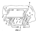
- Utensil handle retainer 20 includes a first flange 30 and a second flange 32 protruding generally outward from interior closure surface 18.
- First flange 30 includes a first distal end 74 positioned away from interior closure surface 18 and a first proximal end 76 positioned where first flange 30 meets interior closure surface 18. First proximal end 76 is thus located nearer interior closure surface 18 than first distal end 74.
- a first flange rib 34 protrudes from first flange 30. In one embodiment, first flange rib 34 extends from interior closure surface 18 to first distal end 74 along the entire height of first flange 30, as illustrated in FIG. 2 .
- a second flange 32 protrudes from interior closure surface 18.
- Second flange 32 includes a second distal end 78 located away from interior closure surface 18 and a second proximal end 80 located where second flange 32 meets interior closure surface 18. Second proximal end 80 is thus located nearer interior closure surface 18 than second distal end 78.
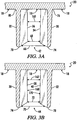
- a second flange rib 36 protrudes from second flange 32 generally toward first flange 30. Second flange rib 36 in some embodiments extends from interior closure surface 18 to second distal end 76 along the entire height of second flange 32, also seen in FIG. 3A , illustrating a detail cross sectional view of Section 3A - 3A from FIG. 2 .
- first tapered retainer gap 42 is defined between first and second flange ribs 34, 36.
- First tapered retainer gap 42 is generally shaped for receiving handle 24 of scooping utensil 22.
- first tapered retainer gap 42 includes a first converging gap section defining a first gap width 66 and a second gap width 68.
- the first gap width 66 is defined nearer the first distal end 74 than the second gap width 68, and the first gap width 66 is greater than the second gap width 68.
- the first converging gap section defined between first and second flange ribs 34, 36 causes a self-centering, or funneling, effect when the utensil handle 24 is inserted into the first tapered retainer gap 42.
- This self-centering, or funneling, effect caused by the first converging gap section provides convenient storage of the utensil handle 24 and prevents the user from having to precisely align the handle 24 with the tapered retainer gap 42 during insertion of the handle 24 into the gap.
- utensil handle retainer 20 includes a third flange rib 38 protruding from first flange 30 and a fourth flange rib 40 protruding from second flange 32.
- a second tapered retainer gap 44 is defined between third and fourth flange ribs 38, 40. Referring to FIG. 3B , a partial cross-sectional view of Section 3B - 3B from FIG. 2 is illustrated.
- Second tapered retainer gap 44 in some embodiments defines a second converging gap section including a fourth gap width 70 and a fifth gap width 72. Fifth gap width 72 is defined nearer interior closure surface 18 than fourth gap width 70, and fifth gap width 72 is less than fourth gap width 70.
- the second converging gap section defined by fourth and fifth gap widths 70, 72 also creates a self-centering, or funneling, effect, in combination with the effect created by the first converging gap section. Together, the first and second converging gap sections provide enhanced ease of use when securing a utensil handle to the utensil handle retainer.
- first flange 30, second flange 32, and first, second, third and fourth flange ribs 34, 36, 38, 40 are all integrally molded on closure 14.
- first flange rib 34 includes a first beveled end 152 oriented at a first bevel angle 58 relative to a reference axis 46.
- Reference axis 46 is aligned substantially parallel to interior closure surface 18.
- Second flange rib 36 in some embodiments also includes a second beveled end 154 oriented at a second bevel angle 60 relative to reference axis 46.
- first and second bevel angles 58, 60 are substantially equal.
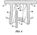
- first and second bevel angles 58, 60 ranging between about 110 degrees and about 170 degrees are suitable for providing the desired self-centering, or funneling, effect experienced when handle 24 is inserted into first tapered retainer gap 42, as illustrated in FIG. 5 .
- utensil handle retainer 20 includes a minimum gap distance A defined at the narrowest distance between first and second flanges 30, 32. Minimum gap distance A in some embodiments is defined at the narrowest point between first and second flange ribs 34, 36 in the first converging gap section of first tapered retainer gap 42.
- Utensil handle 24 generally includes a utensil handle thickness B, as seen in FIG. 5 .
- utensil handle 24 includes a handle body 25 and a handle rib 28 protruding from handle body 25, as best seen in FIG. 1 .
- Handle thickness B in this configuration is defined as the thickness of handle body 25 plus the thickness of handle rib 28.
- a handle interference ratio is defined as the handle thickness B divided by minimum gap distance A. In some embodiments, handle interference ratio is greater than about 1.0.
- utensil handle 24 is inserted between first and second flanges 30, 32.
- First and second flanges 30, 32, and first, second, third and fourth flange ribs 34, 36, 38, 40 in one embodiment include a thermoplastic polymer material, for example polypropylene.
- first and second flanges 30, 32, and flange ribs 34, 36, 38, 40 are resiliently flexible and are capable of bending in an elastic range without undergoing plastic deformation.
- flange ribs 34, 36, 38, 40 provide additional stiffness, or resistance to flex, to first and second flanges 30, 32 during resilient bending.
- the user will insert handle 24 into flange gap 42 after each use to store the scooping utensil 22 until future use. Storage prevents scooping utensil 22 from becoming buried in the stored content.
- the handle interference ratio is greater than about 1.0
- the first and second flanges 30, 32 are pushed apart when handle 24 is inserted into first tapered retainer gap 42.
- the first and second flanges 30, 32 resiliently press against handle 24 during insertion, providing a compressive, or clamping, force against handle 24.
- the utensil handle retainer 20 can be used to secure handle 24 to closure 14 over a wide range of manufacturing tolerances, thereby reducing manufacturing costs associated with precision manufacturing of utensil handle 24 and utensil handle retainer 20.
- utensil handle 24 does not contact first or second flanges 30, 32, but is rather engaged directly by one or more of first, second, third and fourth flange ribs 34, 36, 38, 40.
- handle interference ratio B divided by A
- a practical upper limit is seen at around 3.0.
- a handle interference ratio no greater than about 1.2 provides adequate clamping force while providing suitable dimensional interference for easily securing utensil handle 24 to utensil handle retainer 20.
- first tapered retainer gap 42 includes a third gap width 160 defined between first and second flange ribs 34, 36.
- Third gap width 160 in some embodiments is greater than second gap width 68 and is defined nearer interior closure surface 18 than second gap width 68.
- Third gap width 160 defines a diverging section of first tapered gap 42 between second gap width 68 and interior closure surface 18.
- second tapered retainer gap 44 includes a sixth gap width 162 defined between third and fourth flange ribs 38, 40.
- Sixth gap width 162 in some embodiments is greater than fifth gap width 72 and is defined nearer interior closure surface 18 than fifth gap width 72.
- Sixth gap width 162 defines a diverging section of second tapered retainer gap 44 located between the location of fifth gap width 72 and the interior closure surface 18.
- first flange rib 34 includes a first rib surface 164 substantially facing first tapered retainer gap 42.
- First rib surface 164 is oriented at a first taper angle 50 relative to interior closure surface 18.
- first taper angle 50 is between about ninety and about sixty degrees.
- second flange rib 36 includes a second rib surface 166 substantially facing tapered retainer gap 42.
- Second rib surface 166 is oriented at a second taper angle 52.
- second taper angle 52 is between about ninety and about sixty degrees.
- first and second taper angles 50, 52 are substantially equal.
- first and second taper angles 50, 52 are both acute and are no less than about eighty degrees.
- first and second taper angles 50, 52 between about eight-nine degrees and about eighty-five degrees are sufficient to push handle 24 toward interior closure surface 18 for securely retaining utensil handle 24 in utensil handle retainer 20. It will be appreciated that friction between handle 24 and utensil handle retainer 20 is sufficient to securely retain handle 24 between first and second flanges 30, 32.
- a utensil handle 24 is shown generally secured in utensil handle retainer 20 between first and second flanges 30, 32. More specifically, utensil handle 24 is secured between first and second flange ribs 34, 36, and also between third and fourth flange ribs 38, 40. As seen in FIG. 8 , in some embodiments, handle rib 28 engages flange ribs 34 and 38. Accordingly, in some embodiments, handle rib 28 is positioned in the diverging sections of first and second tapered retainer gaps 42, 44, seen in FIGS. 3A and 3B .
- Positioning of handle rib 28 in the diverging sections of each tapered retainer gap 42, 44 provides additional clamping force to utensil handle 24 for effectively securing scooping utensil 22 to utensil handle retainer 20 without requiring additional structure for engaging the utensil bowl 23.
- This aspect of the present disclosure allows utensils with various sized bowls to be interchangeably used with one utensil retainer configuration.
- container body 12 includes side wall 16 oriented at a side wall angle 116 relative to horizontal reference axis 118.
- side wall angle 116 is substantially perpendicular to horizontal reference axis 118.
- side wall angle 116 is between about eighty degrees and about ninety degrees.
- side wall angle 116 is substantially between about eighty-five and about eighty-nine degrees.
- a base 104 is attached to side wall 116.
- Base 104 forms bottom interior surface 96 of the container body 12.
- the base 104 includes a rounded interior corner defining a first radius of curvature 100 between the side wall 16 and the bottom interior surface 96 of container body 12.
- first radius of curvature 100 is between about ten millimeters and about thirty millimeters.
- the rounded interior corner of base 104 allows enhanced removal of the last amount of any remaining material from container body 12 using scooping utensil 22.
- scooping utensil 22 includes a utensil bowl 23 having a second radius of curvature 102.
- the first radius of curvature 100 is substantially equal to the second radius of curvature 102. It is understood that in some embodiments the utensil bowl 23 can be made of a resilient material that flexibly contours to the first radius of curvature 100.
- FIG. 9 Another aspect of the present disclosure provides a container apparatus having a nesting configuration for stacking multiple like containers in a vertical assembly, as seen in FIG. 9 .
- the vertical nesting configuration facilitates improved display on store or home shelves and improved packaging by preventing like containers from sliding horizontally relative each other when stacked.
- side wall 16 includes a skirt 98 protruding downward from side wall 16. Skirt 98 is coextensive with and is oriented in substantially the same plane as side wall 16. In one embodiment, skirt 98 forms a continuous annular ring surrounding base 104. Skirt 98 includes a skirt end 106 defining the lowest edge of skirt 98. Skirt 98 and side wall 16 define an exterior surface area on container body 12. The exterior surface area is defined as the surface area on the container body between lateral rim 94 and skirt end 106.
- a first stackable container apparatus 10 generally includes a closure 14, or lid, having an annular ridge 110 protruding upward therefrom.
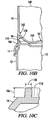
- the annular ridge 110 is shaped for engaging the skirt 98 on a like container, as seen in FIG. 9 and FIG. 10A .
- a second like container 150 having a second container body 148, is positioned above lid 14 of container 10 in a vertically stacked configuration, as seen in detail in FIG. 10A .
- the second container body 148 includes skirt 98 protruding downward from side wall 16.
- Skirt 98 includes a skirt end 106 forming a lower annular edge of skirt 98. Skirt end 106 is shaped for engaging annular ridge 110, as seen in FIG. 10B .
- skirt end 106 surrounds annular ridge 110 when second container body 148 is positioned on lid 14.
- a base 104 is attached to side wall 16 at a base attachment location 142.
- Skirt 98 generally extends downward from the intersection between base 104 and side wall 16.
- skirt 98 defines an inner skirt surface 128, seen in FIG. 10A , substantially facing base 104.
- a base gap 146 is defined between inner skirt surface 128 and base 104.
- Annular ridge 110 is shaped to fit in base gap 146.
- annular ridge 110 includes a ridge height 136 and a ridge width 138. In one specific embodiment, ridge height 136 is between about two to about four millimeters and ridge width 138 is between about one to about two millimeters.
- container body 12 includes a lateral rim 94 protruding outward from container body 12.
- lateral rim 94 extends continuously around the perimeter of container body 12.
- the exterior surface area of container body 12 is covered by a label 124.
- the label 124 partially covers exterior surface area between lateral rim 94 and skirt end 106.
- Label 124 can be an in-mold label affixed to the exterior surface area by an in-mold labeling process wherein container body 12 is formed by injection molding of a thermoplastic or thermosetting material.
- the container body 12 is formed by forcing heated thermoplastic or thermosetting material into an injection mold cavity and allowing the material to cool, forming a solid shape.
- Label 124 is inserted into the mold cavity prior to forcing the thermosetting or thermoforming material into the mold cavity.
- Label 124 in one embodiment is cut from a roll of in-mold labels immediately prior to insertion into the vacant injection mold cavity.
- label 124 includes a glossy exterior surface finish, as opposed to a matte finish.
- label 124 is integrally affixed directly to exterior surface area of container body 12. This technique is referred to as in-mold labeling.
- the label 124 covers at least about ninety-five percent of exterior surface area of the container body 12 between lateral rim 94 and skirt end 106.
- label 124 extends from the lateral rim 94 to a distance above the skirt end 106, leaving an unlabeled region 126 on the container body 12.
- unlabeled region 126 constitutes less than about one percent of exterior surface area of container body 12.
- a container 10 having substantially straight side walls, a low draft angle and a glossy label covering a large portion, i.e. greater than about 95%, of the exterior surface area on the container body 12.
- a straight side wall 16 and low draft angle improves bulk volumetric container packaging efficiency, allowing more containers to be positioned adjacent one another in a fixed space on store shelves or in shipping containers.
- a glossy label is more appealing to customers.
- maximizing the label coverage on the exterior side wall surface area improves the overall aesthetic design and provides more area for informational or decorative label content.
Landscapes
- Engineering & Computer Science (AREA)
- Mechanical Engineering (AREA)
- Details Of Rigid Or Semi-Rigid Containers (AREA)
- Stackable Containers (AREA)
- Closures For Containers (AREA)
Priority Applications (1)
| Application Number | Priority Date | Filing Date | Title |
|---|---|---|---|
| PL11729532T PL2534066T5 (pl) | 2010-06-28 | 2011-06-23 | Pojemnik z elementem nabierającym i mocowaniem elementu nabierającego w pokrywie |
Applications Claiming Priority (2)
| Application Number | Priority Date | Filing Date | Title |
|---|---|---|---|
| US12/824,447 US8376179B2 (en) | 2010-06-28 | 2010-06-28 | Container and closure |
| PCT/US2011/041616 WO2012009125A1 (en) | 2010-06-28 | 2011-06-23 | Container with scooping untensil and scooping retainer in the closure |
Publications (3)
| Publication Number | Publication Date |
|---|---|
| EP2534066A1 EP2534066A1 (en) | 2012-12-19 |
| EP2534066B1 EP2534066B1 (en) | 2014-08-06 |
| EP2534066B2 true EP2534066B2 (en) | 2018-04-18 |
Family
ID=44312426
Family Applications (1)
| Application Number | Title | Priority Date | Filing Date |
|---|---|---|---|
| EP11729532.9A Active EP2534066B2 (en) | 2010-06-28 | 2011-06-23 | Container with scooping utensil and scooping retainer in the closure |
Country Status (17)
| Country | Link |
|---|---|
| US (2) | US8376179B2 (pl) |
| EP (1) | EP2534066B2 (pl) |
| CN (1) | CN102791591B (pl) |
| BR (1) | BR112012023316A2 (pl) |
| CA (1) | CA2791811C (pl) |
| CO (1) | CO6630165A2 (pl) |
| EC (1) | ECSP12012237A (pl) |
| ES (1) | ES2498923T5 (pl) |
| MX (1) | MX2012012148A (pl) |
| MY (1) | MY157308A (pl) |
| PE (1) | PE20131073A1 (pl) |
| PH (1) | PH12012501726A1 (pl) |
| PL (1) | PL2534066T5 (pl) |
| RU (1) | RU2012141279A (pl) |
| SG (1) | SG183851A1 (pl) |
| TW (1) | TWI510411B (pl) |
| WO (1) | WO2012009125A1 (pl) |
Families Citing this family (36)
| Publication number | Priority date | Publication date | Assignee | Title |
|---|---|---|---|---|
| AU2010337353B2 (en) * | 2009-12-29 | 2014-06-05 | Nestec S.A. | Dispensing apparatus having an overcap and scoop |
| MX2012007816A (es) * | 2011-07-01 | 2013-02-07 | Weatherchem Corp | Cierre con mecanismo de retencion de utensilio. |
| USD734149S1 (en) * | 2011-09-22 | 2015-07-14 | PBM Nutritionals, LLC | Canister cover |
| EP2639175B1 (de) * | 2012-03-12 | 2014-06-04 | Rotho Kunststoff AG | Stapelbehältersystem |
| WO2014116838A1 (en) | 2013-01-24 | 2014-07-31 | PBM Nutritionals, LLC | Apparatus and method for making canister and for detecting leaks for quality assurance |
| CN103287712B (zh) * | 2013-06-24 | 2015-09-02 | 启东市天汾电动工具技术创新中心 | 具有取物勺的储物罐 |
| CN105173328A (zh) * | 2013-06-24 | 2015-12-23 | 胡小青 | 一种包装罐底罐组件 |
| CN105173366A (zh) * | 2013-06-24 | 2015-12-23 | 胡小青 | 一种具有奶粉勺的罐盖组件 |
| CN105730862A (zh) * | 2013-06-24 | 2016-07-06 | 李建勋 | 具有取物勺的包装罐 |
| US20150197381A1 (en) * | 2014-01-10 | 2015-07-16 | Jerome A. Valenti | Container with a mountable scoop |
| US9387962B2 (en) * | 2014-01-28 | 2016-07-12 | Mead Johnson Nutrition Company | Resealable container with collar and lid |
| US9505534B2 (en) * | 2014-01-28 | 2016-11-29 | Mead Johnson Nutrition (Asia Pacific) Pte. Ltd. | Resealable container with collar and lid |
| US20160000268A1 (en) * | 2014-07-01 | 2016-01-07 | Mead Johnson Nutrition Company | Measuring device and container |
| EP3177541B1 (en) * | 2014-08-07 | 2019-07-24 | AptarGroup, Inc. | Closure for a container and utensil therefor |
| USD756778S1 (en) | 2015-01-14 | 2016-05-24 | Mead Johnson Nutrition Company | Closure |
| USD790343S1 (en) | 2015-01-14 | 2017-06-27 | Mead Johnson Nutrition Company | Closure |
| HK1250361A1 (zh) * | 2015-02-25 | 2018-12-14 | Munchkin, Inc. | 带有组合的勺夹持器和刮板的粉末分配容器 |
| US20160270577A1 (en) * | 2015-03-16 | 2016-09-22 | Adnan Lekic | Efficient belt storage unit |
| US10239675B2 (en) * | 2015-05-01 | 2019-03-26 | Red Forest Tech, Llc | Integrated product scoop or dispenser holder or clip, methods of production and uses thereof |
| USD797647S1 (en) * | 2016-09-16 | 2017-09-19 | Tailbrella, LLC | Table for vehicle umbrella receptacle |
| US20180194525A1 (en) * | 2017-01-12 | 2018-07-12 | Leprino Performance Brands LLC | Container system |
| USD823076S1 (en) | 2017-01-16 | 2018-07-17 | Target Brands, Inc. | Scoop |
| US11903486B2 (en) * | 2017-07-31 | 2024-02-20 | Bijan Dokhanian | Step stool |
| CN108341182A (zh) * | 2017-09-04 | 2018-07-31 | 中久物流有限公司 | 大型物流容器的防尘盖 |
| USD862999S1 (en) | 2018-02-19 | 2019-10-15 | Target Brands, Inc. | Scoop |
| USD937678S1 (en) | 2018-02-19 | 2021-12-07 | Target Brands, Inc. | Container cover |
| GB201802943D0 (en) * | 2018-02-23 | 2018-04-11 | Mead Johnson Nutrition Co | Improved flip top plastic lid |
| USD849537S1 (en) * | 2018-02-26 | 2019-05-28 | Dean W. Wallwey | Scoop holder |
| US20210130048A1 (en) * | 2018-04-09 | 2021-05-06 | Abbott Laboratories | Powder container with first and second hinged closures |
| US10954037B1 (en) | 2018-09-14 | 2021-03-23 | Antonio Valdes Ibarra | Container with internally incorporated hook assembly |
| US10687682B2 (en) * | 2018-10-15 | 2020-06-23 | Brendan Petit | Applicator storage box |
| JP7241607B2 (ja) * | 2019-06-03 | 2023-03-17 | 大王製紙株式会社 | 家庭用薄葉紙収納容器 |
| WO2023016857A1 (en) * | 2021-08-13 | 2023-02-16 | Unilever Ip Holdings B.V. | Closure with a detachable applicator and container |
| USD1084859S1 (en) * | 2022-03-30 | 2025-07-22 | Jared Peter Grandy | Scoop holder |
| EP4499524A4 (en) | 2022-03-30 | 2026-03-18 | Grand Marlin Capital Llc | BOTTLE AND CONTAINER SUPPORT SET |
| CN117775508B (zh) * | 2024-02-28 | 2024-07-26 | 汕头市甜甜乐糖果食品有限公司 | 一种新型的包装容器及成型设备 |
Family Cites Families (34)
| Publication number | Priority date | Publication date | Assignee | Title |
|---|---|---|---|---|
| US1959600A (en) * | 1933-03-01 | 1934-05-22 | Adam A Schneider | Toothbrush holder |
| US3623634A (en) * | 1969-11-03 | 1971-11-30 | Johanness Norgard | Modular container |
| US4471881A (en) | 1983-06-28 | 1984-09-18 | J. L. Clark Manufacturing Co. | Container with metal body and plastic hinge |
| US4848714A (en) * | 1987-10-09 | 1989-07-18 | Ziaylek Theodore Jun | Mounting plate with rollers |
| US5052556A (en) * | 1990-09-26 | 1991-10-01 | Wilkinson William T | Toothbrush traveling case |
| JPH0741648B2 (ja) * | 1990-12-28 | 1995-05-10 | 日プラ株式会社 | 糸底付きインモールドラベリング容器及びその製造方法 |
| US5312011A (en) * | 1992-08-13 | 1994-05-17 | Ultradent Products, Inc. | Stackable container system |
| CA2096569A1 (en) * | 1993-05-19 | 1994-11-20 | Verelk Bedrossian | Paint bucket with inner paint implement attaching means |
| US5586656A (en) * | 1995-01-13 | 1996-12-24 | Abrums; Rolin L. | Nestable and stackable storage unit |
| DE19546684A1 (de) | 1995-12-14 | 1997-06-19 | Boehringer Mannheim Gmbh | Vorratsbehältnis für streifenförmige Testelemente |
| US5706974A (en) | 1995-12-20 | 1998-01-13 | Abbott Laboratories | Can for powder products having scoop retaining means |
| FR2747107A1 (fr) | 1996-04-04 | 1997-10-10 | Bois Jacques | Dispositif permettant d'obtenir en une seule piece un couvercle et une mesurette dont le rangement est inclu dans le couvercle |
| DE19815364A1 (de) | 1998-03-28 | 1999-09-30 | Grt Verpackungen Aus Kunststof | Deckel mit befestigtem Einmalbesteck |
| US6619498B2 (en) * | 2000-01-27 | 2003-09-16 | Von Holdt, Jr. John W. | Plastic container and lid construction |
| US6772904B1 (en) | 2000-05-26 | 2004-08-10 | Kraft Foods Holdings, Inc. | Container for food products |
| US6761283B1 (en) | 2000-05-26 | 2004-07-13 | Kraft Foods Holdings, Inc. | Food product container with closure |
| DE20120761U1 (de) | 2001-12-21 | 2002-03-14 | H + S Automatisierungstechnik GmbH, 64853 Otzberg | Aufnahme von Kleinteilen |
| FR2845671B1 (fr) * | 2002-10-14 | 2005-06-24 | Techpack Int | Distributeur echantillon de produit solide, semi-solide ou pateux |
| US20040099566A1 (en) * | 2002-11-25 | 2004-05-27 | Kipperman Stuart R. | Container |
| US7185796B2 (en) * | 2003-10-08 | 2007-03-06 | Armament Systems & Procedures, Inc. | Baton scabbard with roller clamp retention |
| CN1914096B (zh) * | 2004-02-05 | 2011-07-06 | 努特里奇亚有限公司 | 粉状材料的包装 |
| GB0404145D0 (en) | 2004-02-25 | 2004-03-31 | Pactiv Uk Ltd | "Tamper Evident Container" |
| GB0404152D0 (en) | 2004-02-25 | 2004-03-31 | Pactiv Uk Ltd | "Tamper evident container" |
| US8042704B2 (en) | 2005-01-19 | 2011-10-25 | Plastipak Packaging, Inc. | Container with measuring device holding means |
| US7464475B2 (en) | 2005-11-10 | 2008-12-16 | Charng-Shing Tsao | Concealed spoon in milk powder container |
| MX2009007052A (es) | 2006-12-27 | 2009-09-04 | Abbott Lab | Contenedor. |
| US20080156858A1 (en) | 2006-12-27 | 2008-07-03 | Perry James P | Container |
| FR2915969B1 (fr) * | 2007-05-11 | 2011-12-23 | Gervais Danone Sa | Emballage pour produit alimentaire preleve avec un dispositif doseur |
| US8672172B2 (en) | 2007-07-27 | 2014-03-18 | Mcneil-Ppc, Inc. | Organizer system |
| US7775395B2 (en) | 2007-08-03 | 2010-08-17 | Huhtamaki, Inc. | Hinged lid for a food container |
| US9004282B2 (en) | 2007-08-20 | 2015-04-14 | William Van Ness | Food storage bin |
| WO2009081050A2 (fr) | 2007-12-19 | 2009-07-02 | Compagnie Gervais Danone | Emballage alimentaire avec couvercle et systeme de fermeture pour un emballage |
| CN102026890B (zh) | 2008-05-15 | 2012-05-09 | Csp技术公司 | 容器、用于材料条的分配器以及一种制造分配器的方法 |
| WO2012047891A2 (en) | 2010-10-06 | 2012-04-12 | Abbott Laboratories | Packaging for powdered beverage |
-
2010
- 2010-06-28 US US12/824,447 patent/US8376179B2/en active Active
-
2011
- 2011-06-23 SG SG2012064739A patent/SG183851A1/en unknown
- 2011-06-23 BR BR112012023316A patent/BR112012023316A2/pt not_active IP Right Cessation
- 2011-06-23 WO PCT/US2011/041616 patent/WO2012009125A1/en not_active Ceased
- 2011-06-23 RU RU2012141279/12A patent/RU2012141279A/ru not_active Application Discontinuation
- 2011-06-23 PH PH1/2012/501726A patent/PH12012501726A1/en unknown
- 2011-06-23 MX MX2012012148A patent/MX2012012148A/es active IP Right Grant
- 2011-06-23 MY MYPI2012003893A patent/MY157308A/en unknown
- 2011-06-23 PE PE2012002047A patent/PE20131073A1/es not_active Application Discontinuation
- 2011-06-23 CA CA2791811A patent/CA2791811C/en not_active Expired - Fee Related
- 2011-06-23 EP EP11729532.9A patent/EP2534066B2/en active Active
- 2011-06-23 PL PL11729532T patent/PL2534066T5/pl unknown
- 2011-06-23 ES ES11729532.9T patent/ES2498923T5/es active Active
- 2011-06-23 CN CN201180013989.4A patent/CN102791591B/zh active Active
- 2011-06-27 TW TW100122444A patent/TWI510411B/zh not_active IP Right Cessation
-
2012
- 2012-10-08 EC ECSP12012237 patent/ECSP12012237A/es unknown
- 2012-10-30 CO CO12195506A patent/CO6630165A2/es active IP Right Grant
-
2013
- 2013-01-11 US US13/739,535 patent/US9090391B2/en active Active
Also Published As
| Publication number | Publication date |
|---|---|
| MY157308A (en) | 2016-05-31 |
| CA2791811A1 (en) | 2012-01-19 |
| US9090391B2 (en) | 2015-07-28 |
| ECSP12012237A (es) | 2012-11-30 |
| ES2498923T5 (es) | 2018-06-19 |
| WO2012009125A8 (en) | 2012-10-26 |
| CA2791811C (en) | 2018-09-18 |
| PH12012501726A1 (en) | 2014-12-03 |
| CO6630165A2 (es) | 2013-03-01 |
| TWI510411B (zh) | 2015-12-01 |
| CN102791591A (zh) | 2012-11-21 |
| TW201219269A (en) | 2012-05-16 |
| WO2012009125A1 (en) | 2012-01-19 |
| EP2534066B1 (en) | 2014-08-06 |
| CN102791591B (zh) | 2015-04-29 |
| US8376179B2 (en) | 2013-02-19 |
| RU2012141279A (ru) | 2014-04-10 |
| PE20131073A1 (es) | 2013-09-14 |
| US20110315586A1 (en) | 2011-12-29 |
| EP2534066A1 (en) | 2012-12-19 |
| US20130134057A1 (en) | 2013-05-30 |
| ES2498923T3 (es) | 2014-09-26 |
| MX2012012148A (es) | 2012-11-21 |
| PL2534066T3 (pl) | 2015-01-30 |
| BR112012023316A2 (pt) | 2019-09-24 |
| SG183851A1 (en) | 2012-10-30 |
| PL2534066T5 (pl) | 2019-07-31 |
| HK1178867A1 (en) | 2013-09-19 |
Similar Documents
| Publication | Publication Date | Title |
|---|---|---|
| EP2534066B1 (en) | Container with scooping utensil and scooping retainer in the closure | |
| US6772904B1 (en) | Container for food products | |
| US7040500B2 (en) | Container and scoop arrangement | |
| EP1157936A2 (en) | Food product container with closure | |
| US20080156858A1 (en) | Container | |
| WO2007041488A2 (en) | Modular container assembly and merchandizing container display | |
| EP3326931A1 (en) | Container with hinge lid | |
| EP1786700A2 (en) | Consumables container with nested insert | |
| US20170334612A1 (en) | Container | |
| CA2791809C (en) | Container seal with deflecting lip | |
| US20210237959A1 (en) | Container with reinforced bottom | |
| US20070163914A1 (en) | Package closure | |
| HK1178867B (en) | Container for storing material | |
| KR20040054462A (ko) | 다수의 수용 내용물에 대한 독립적 밀폐 및 사용이 용이한식품보관용기 | |
| FI106444B (fi) | Lisävaruste (säilytys)rasiaan | |
| EP1584566B1 (en) | Plastic container with annular collar and method of its manufacture | |
| JP3915051B2 (ja) | ペースト状化粧品等収納容器 | |
| HK1088871B (en) | Easy to empty container |
Legal Events
| Date | Code | Title | Description |
|---|---|---|---|
| PUAI | Public reference made under article 153(3) epc to a published international application that has entered the european phase |
Free format text: ORIGINAL CODE: 0009012 |
|
| 17P | Request for examination filed |
Effective date: 20120914 |
|
| AK | Designated contracting states |
Kind code of ref document: A1 Designated state(s): AL AT BE BG CH CY CZ DE DK EE ES FI FR GB GR HR HU IE IS IT LI LT LU LV MC MK MT NL NO PL PT RO RS SE SI SK SM TR |
|
| RAP1 | Party data changed (applicant data changed or rights of an application transferred) |
Owner name: MJN U.S. HOLDINGS LLC |
|
| DAX | Request for extension of the european patent (deleted) | ||
| REG | Reference to a national code |
Ref country code: DE Ref legal event code: R079 Ref document number: 602011008918 Country of ref document: DE Free format text: PREVIOUS MAIN CLASS: B65D0077240000 Ipc: B65D0043160000 |
|
| RIC1 | Information provided on ipc code assigned before grant |
Ipc: B65D 21/02 20060101ALI20131210BHEP Ipc: B65D 51/24 20060101ALI20131210BHEP Ipc: B65D 83/00 20060101ALI20131210BHEP Ipc: B65D 43/16 20060101AFI20131210BHEP |
|
| GRAP | Despatch of communication of intention to grant a patent |
Free format text: ORIGINAL CODE: EPIDOSNIGR1 |
|
| INTG | Intention to grant announced |
Effective date: 20140228 |
|
| GRAS | Grant fee paid |
Free format text: ORIGINAL CODE: EPIDOSNIGR3 |
|
| GRAA | (expected) grant |
Free format text: ORIGINAL CODE: 0009210 |
|
| AK | Designated contracting states |
Kind code of ref document: B1 Designated state(s): AL AT BE BG CH CY CZ DE DK EE ES FI FR GB GR HR HU IE IS IT LI LT LU LV MC MK MT NL NO PL PT RO RS SE SI SK SM TR |
|
| REG | Reference to a national code |
Ref country code: GB Ref legal event code: FG4D |
|
| REG | Reference to a national code |
Ref country code: CH Ref legal event code: EP Ref country code: AT Ref legal event code: REF Ref document number: 680921 Country of ref document: AT Kind code of ref document: T Effective date: 20140815 |
|
| REG | Reference to a national code |
Ref country code: IE Ref legal event code: FG4D |
|
| REG | Reference to a national code |
Ref country code: DE Ref legal event code: R096 Ref document number: 602011008918 Country of ref document: DE Effective date: 20140918 |
|
| REG | Reference to a national code |
Ref country code: ES Ref legal event code: FG2A Ref document number: 2498923 Country of ref document: ES Kind code of ref document: T3 Effective date: 20140926 |
|
| REG | Reference to a national code |
Ref country code: SE Ref legal event code: TRGR |
|
| REG | Reference to a national code |
Ref country code: NO Ref legal event code: T2 Effective date: 20140806 |
|
| REG | Reference to a national code |
Ref country code: NL Ref legal event code: T3 |
|
| REG | Reference to a national code |
Ref country code: AT Ref legal event code: MK05 Ref document number: 680921 Country of ref document: AT Kind code of ref document: T Effective date: 20140806 |
|
| REG | Reference to a national code |
Ref country code: LT Ref legal event code: MG4D |
|
| PG25 | Lapsed in a contracting state [announced via postgrant information from national office to epo] |
Ref country code: LT Free format text: LAPSE BECAUSE OF FAILURE TO SUBMIT A TRANSLATION OF THE DESCRIPTION OR TO PAY THE FEE WITHIN THE PRESCRIBED TIME-LIMIT Effective date: 20140806 Ref country code: GR Free format text: LAPSE BECAUSE OF FAILURE TO SUBMIT A TRANSLATION OF THE DESCRIPTION OR TO PAY THE FEE WITHIN THE PRESCRIBED TIME-LIMIT Effective date: 20141107 Ref country code: PT Free format text: LAPSE BECAUSE OF FAILURE TO SUBMIT A TRANSLATION OF THE DESCRIPTION OR TO PAY THE FEE WITHIN THE PRESCRIBED TIME-LIMIT Effective date: 20141209 Ref country code: FI Free format text: LAPSE BECAUSE OF FAILURE TO SUBMIT A TRANSLATION OF THE DESCRIPTION OR TO PAY THE FEE WITHIN THE PRESCRIBED TIME-LIMIT Effective date: 20140806 Ref country code: BG Free format text: LAPSE BECAUSE OF FAILURE TO SUBMIT A TRANSLATION OF THE DESCRIPTION OR TO PAY THE FEE WITHIN THE PRESCRIBED TIME-LIMIT Effective date: 20141106 |
|
| REG | Reference to a national code |
Ref country code: PL Ref legal event code: T3 |
|
| PG25 | Lapsed in a contracting state [announced via postgrant information from national office to epo] |
Ref country code: LV Free format text: LAPSE BECAUSE OF FAILURE TO SUBMIT A TRANSLATION OF THE DESCRIPTION OR TO PAY THE FEE WITHIN THE PRESCRIBED TIME-LIMIT Effective date: 20140806 Ref country code: HR Free format text: LAPSE BECAUSE OF FAILURE TO SUBMIT A TRANSLATION OF THE DESCRIPTION OR TO PAY THE FEE WITHIN THE PRESCRIBED TIME-LIMIT Effective date: 20140806 Ref country code: AT Free format text: LAPSE BECAUSE OF FAILURE TO SUBMIT A TRANSLATION OF THE DESCRIPTION OR TO PAY THE FEE WITHIN THE PRESCRIBED TIME-LIMIT Effective date: 20140806 Ref country code: CY Free format text: LAPSE BECAUSE OF FAILURE TO SUBMIT A TRANSLATION OF THE DESCRIPTION OR TO PAY THE FEE WITHIN THE PRESCRIBED TIME-LIMIT Effective date: 20140806 Ref country code: IS Free format text: LAPSE BECAUSE OF FAILURE TO SUBMIT A TRANSLATION OF THE DESCRIPTION OR TO PAY THE FEE WITHIN THE PRESCRIBED TIME-LIMIT Effective date: 20141206 Ref country code: RS Free format text: LAPSE BECAUSE OF FAILURE TO SUBMIT A TRANSLATION OF THE DESCRIPTION OR TO PAY THE FEE WITHIN THE PRESCRIBED TIME-LIMIT Effective date: 20140806 |
|
| PG25 | Lapsed in a contracting state [announced via postgrant information from national office to epo] |
Ref country code: RO Free format text: LAPSE BECAUSE OF FAILURE TO SUBMIT A TRANSLATION OF THE DESCRIPTION OR TO PAY THE FEE WITHIN THE PRESCRIBED TIME-LIMIT Effective date: 20140806 Ref country code: EE Free format text: LAPSE BECAUSE OF FAILURE TO SUBMIT A TRANSLATION OF THE DESCRIPTION OR TO PAY THE FEE WITHIN THE PRESCRIBED TIME-LIMIT Effective date: 20140806 Ref country code: DK Free format text: LAPSE BECAUSE OF FAILURE TO SUBMIT A TRANSLATION OF THE DESCRIPTION OR TO PAY THE FEE WITHIN THE PRESCRIBED TIME-LIMIT Effective date: 20140806 |
|
| REG | Reference to a national code |
Ref country code: SK Ref legal event code: T3 Ref document number: E 18090 Country of ref document: SK Ref country code: DE Ref legal event code: R026 Ref document number: 602011008918 Country of ref document: DE |
|
| PLBI | Opposition filed |
Free format text: ORIGINAL CODE: 0009260 |
|
| PLAX | Notice of opposition and request to file observation + time limit sent |
Free format text: ORIGINAL CODE: EPIDOSNOBS2 |
|
| 26 | Opposition filed |
Opponent name: NESTEC S.A. Effective date: 20150505 |
|
| PGFP | Annual fee paid to national office [announced via postgrant information from national office to epo] |
Ref country code: CZ Payment date: 20150604 Year of fee payment: 5 |
|
| PLBB | Reply of patent proprietor to notice(s) of opposition received |
Free format text: ORIGINAL CODE: EPIDOSNOBS3 |
|
| PG25 | Lapsed in a contracting state [announced via postgrant information from national office to epo] |
Ref country code: SI Free format text: LAPSE BECAUSE OF FAILURE TO SUBMIT A TRANSLATION OF THE DESCRIPTION OR TO PAY THE FEE WITHIN THE PRESCRIBED TIME-LIMIT Effective date: 20140806 |
|
| PG25 | Lapsed in a contracting state [announced via postgrant information from national office to epo] |
Ref country code: MC Free format text: LAPSE BECAUSE OF FAILURE TO SUBMIT A TRANSLATION OF THE DESCRIPTION OR TO PAY THE FEE WITHIN THE PRESCRIBED TIME-LIMIT Effective date: 20140806 |
|
| PG25 | Lapsed in a contracting state [announced via postgrant information from national office to epo] |
Ref country code: LU Free format text: LAPSE BECAUSE OF FAILURE TO SUBMIT A TRANSLATION OF THE DESCRIPTION OR TO PAY THE FEE WITHIN THE PRESCRIBED TIME-LIMIT Effective date: 20150623 |
|
| REG | Reference to a national code |
Ref country code: IE Ref legal event code: MM4A |
|
| PG25 | Lapsed in a contracting state [announced via postgrant information from national office to epo] |
Ref country code: IE Free format text: LAPSE BECAUSE OF NON-PAYMENT OF DUE FEES Effective date: 20150623 |
|
| REG | Reference to a national code |
Ref country code: FR Ref legal event code: PLFP Year of fee payment: 6 |
|
| PG25 | Lapsed in a contracting state [announced via postgrant information from national office to epo] |
Ref country code: BE Free format text: LAPSE BECAUSE OF FAILURE TO SUBMIT A TRANSLATION OF THE DESCRIPTION OR TO PAY THE FEE WITHIN THE PRESCRIBED TIME-LIMIT Effective date: 20140806 |
|
| PG25 | Lapsed in a contracting state [announced via postgrant information from national office to epo] |
Ref country code: MT Free format text: LAPSE BECAUSE OF FAILURE TO SUBMIT A TRANSLATION OF THE DESCRIPTION OR TO PAY THE FEE WITHIN THE PRESCRIBED TIME-LIMIT Effective date: 20140806 |
|
| PG25 | Lapsed in a contracting state [announced via postgrant information from national office to epo] |
Ref country code: CZ Free format text: LAPSE BECAUSE OF NON-PAYMENT OF DUE FEES Effective date: 20160623 |
|
| REG | Reference to a national code |
Ref country code: FR Ref legal event code: PLFP Year of fee payment: 7 |
|
| PG25 | Lapsed in a contracting state [announced via postgrant information from national office to epo] |
Ref country code: SM Free format text: LAPSE BECAUSE OF FAILURE TO SUBMIT A TRANSLATION OF THE DESCRIPTION OR TO PAY THE FEE WITHIN THE PRESCRIBED TIME-LIMIT Effective date: 20140806 Ref country code: HU Free format text: LAPSE BECAUSE OF FAILURE TO SUBMIT A TRANSLATION OF THE DESCRIPTION OR TO PAY THE FEE WITHIN THE PRESCRIBED TIME-LIMIT; INVALID AB INITIO Effective date: 20110623 |
|
| PGFP | Annual fee paid to national office [announced via postgrant information from national office to epo] |
Ref country code: IE Payment date: 20170421 Year of fee payment: 7 |
|
| PG25 | Lapsed in a contracting state [announced via postgrant information from national office to epo] |
Ref country code: TR Free format text: LAPSE BECAUSE OF FAILURE TO SUBMIT A TRANSLATION OF THE DESCRIPTION OR TO PAY THE FEE WITHIN THE PRESCRIBED TIME-LIMIT Effective date: 20140806 |
|
| APAH | Appeal reference modified |
Free format text: ORIGINAL CODE: EPIDOSCREFNO |
|
| APBM | Appeal reference recorded |
Free format text: ORIGINAL CODE: EPIDOSNREFNO |
|
| APBP | Date of receipt of notice of appeal recorded |
Free format text: ORIGINAL CODE: EPIDOSNNOA2O |
|
| PLAB | Opposition data, opponent's data or that of the opponent's representative modified |
Free format text: ORIGINAL CODE: 0009299OPPO |
|
| APBU | Appeal procedure closed |
Free format text: ORIGINAL CODE: EPIDOSNNOA9O |
|
| R26 | Opposition filed (corrected) |
Opponent name: NESTEC S.A. Effective date: 20150505 |
|
| RIN2 | Information on inventor provided after grant (corrected) |
Inventor name: HORTON, THOMAS C., Inventor name: MINNETTE, JEFFREY, Inventor name: WIGGINS, ROBIN, Inventor name: JULIAN, RANDALL, |
|
| RAP2 | Party data changed (patent owner data changed or rights of a patent transferred) |
Owner name: MJN U.S. HOLDINGS LLC |
|
| PUAH | Patent maintained in amended form |
Free format text: ORIGINAL CODE: 0009272 |
|
| STAA | Information on the status of an ep patent application or granted ep patent |
Free format text: STATUS: PATENT MAINTAINED AS AMENDED |
|
| 27A | Patent maintained in amended form |
Effective date: 20180418 |
|
| AK | Designated contracting states |
Kind code of ref document: B2 Designated state(s): AL AT BE BG CH CY CZ DE DK EE ES FI FR GB GR HR HU IE IS IT LI LT LU LV MC MK MT NL NO PL PT RO RS SE SI SK SM TR |
|
| REG | Reference to a national code |
Ref country code: DE Ref legal event code: R102 Ref document number: 602011008918 Country of ref document: DE |
|
| REG | Reference to a national code |
Ref country code: CH Ref legal event code: AELC |
|
| REG | Reference to a national code |
Ref country code: FR Ref legal event code: PLFP Year of fee payment: 8 |
|
| REG | Reference to a national code |
Ref country code: ES Ref legal event code: DC2A Ref document number: 2498923 Country of ref document: ES Kind code of ref document: T5 Effective date: 20180619 |
|
| PG25 | Lapsed in a contracting state [announced via postgrant information from national office to epo] |
Ref country code: MK Free format text: LAPSE BECAUSE OF FAILURE TO SUBMIT A TRANSLATION OF THE DESCRIPTION OR TO PAY THE FEE WITHIN THE PRESCRIBED TIME-LIMIT Effective date: 20140806 |
|
| REG | Reference to a national code |
Ref country code: SE Ref legal event code: RPEO |
|
| REG | Reference to a national code |
Ref country code: NL Ref legal event code: FP |
|
| REG | Reference to a national code |
Ref country code: NO Ref legal event code: TB2 |
|
| PG25 | Lapsed in a contracting state [announced via postgrant information from national office to epo] |
Ref country code: AL Free format text: LAPSE BECAUSE OF FAILURE TO SUBMIT A TRANSLATION OF THE DESCRIPTION OR TO PAY THE FEE WITHIN THE PRESCRIBED TIME-LIMIT Effective date: 20140806 |
|
| REG | Reference to a national code |
Ref country code: SK Ref legal event code: MM4A Ref document number: E 18090 Country of ref document: SK Effective date: 20180623 |
|
| PG25 | Lapsed in a contracting state [announced via postgrant information from national office to epo] |
Ref country code: SK Free format text: LAPSE BECAUSE OF NON-PAYMENT OF DUE FEES Effective date: 20180623 |
|
| PGFP | Annual fee paid to national office [announced via postgrant information from national office to epo] |
Ref country code: IT Payment date: 20210511 Year of fee payment: 11 Ref country code: NO Payment date: 20210609 Year of fee payment: 11 |
|
| PGFP | Annual fee paid to national office [announced via postgrant information from national office to epo] |
Ref country code: CH Payment date: 20210616 Year of fee payment: 11 Ref country code: PL Payment date: 20210414 Year of fee payment: 11 Ref country code: SE Payment date: 20210610 Year of fee payment: 11 |
|
| PGFP | Annual fee paid to national office [announced via postgrant information from national office to epo] |
Ref country code: ES Payment date: 20210707 Year of fee payment: 11 |
|
| REG | Reference to a national code |
Ref country code: NO Ref legal event code: MMEP |
|
| REG | Reference to a national code |
Ref country code: CH Ref legal event code: PL Ref country code: SE Ref legal event code: EUG |
|
| PG25 | Lapsed in a contracting state [announced via postgrant information from national office to epo] |
Ref country code: SE Free format text: LAPSE BECAUSE OF NON-PAYMENT OF DUE FEES Effective date: 20220624 Ref country code: NO Free format text: LAPSE BECAUSE OF NON-PAYMENT OF DUE FEES Effective date: 20220630 Ref country code: LI Free format text: LAPSE BECAUSE OF NON-PAYMENT OF DUE FEES Effective date: 20220630 Ref country code: CH Free format text: LAPSE BECAUSE OF NON-PAYMENT OF DUE FEES Effective date: 20220630 |
|
| P01 | Opt-out of the competence of the unified patent court (upc) registered |
Effective date: 20230513 |
|
| PG25 | Lapsed in a contracting state [announced via postgrant information from national office to epo] |
Ref country code: IT Free format text: LAPSE BECAUSE OF NON-PAYMENT OF DUE FEES Effective date: 20220623 |
|
| PGFP | Annual fee paid to national office [announced via postgrant information from national office to epo] |
Ref country code: FR Payment date: 20230510 Year of fee payment: 13 |
|
| REG | Reference to a national code |
Ref country code: ES Ref legal event code: FD2A Effective date: 20230731 |
|
| PG25 | Lapsed in a contracting state [announced via postgrant information from national office to epo] |
Ref country code: PL Free format text: LAPSE BECAUSE OF NON-PAYMENT OF DUE FEES Effective date: 20220623 |
|
| PG25 | Lapsed in a contracting state [announced via postgrant information from national office to epo] |
Ref country code: ES Free format text: LAPSE BECAUSE OF NON-PAYMENT OF DUE FEES Effective date: 20220624 |
|
| PGFP | Annual fee paid to national office [announced via postgrant information from national office to epo] |
Ref country code: GB Payment date: 20240402 Year of fee payment: 14 |
|
| PGFP | Annual fee paid to national office [announced via postgrant information from national office to epo] |
Ref country code: DE Payment date: 20240328 Year of fee payment: 14 |
|
| PG25 | Lapsed in a contracting state [announced via postgrant information from national office to epo] |
Ref country code: FR Free format text: LAPSE BECAUSE OF NON-PAYMENT OF DUE FEES Effective date: 20240630 |
|
| PGFP | Annual fee paid to national office [announced via postgrant information from national office to epo] |
Ref country code: NL Payment date: 20250409 Year of fee payment: 15 |
|
| REG | Reference to a national code |
Ref country code: DE Ref legal event code: R119 Ref document number: 602011008918 Country of ref document: DE |
|
| GBPC | Gb: european patent ceased through non-payment of renewal fee |
Effective date: 20250623 |
|
| PG25 | Lapsed in a contracting state [announced via postgrant information from national office to epo] |
Ref country code: GB Free format text: LAPSE BECAUSE OF NON-PAYMENT OF DUE FEES Effective date: 20250623 |
|
| PG25 | Lapsed in a contracting state [announced via postgrant information from national office to epo] |
Ref country code: DE Free format text: LAPSE BECAUSE OF NON-PAYMENT OF DUE FEES Effective date: 20260101 |