EP2535167B1 - Machine de formage par soufflage avec arbre de pivotement guidé par palier lisse - Google Patents
Machine de formage par soufflage avec arbre de pivotement guidé par palier lisse Download PDFInfo
- Publication number
- EP2535167B1 EP2535167B1 EP12172380.3A EP12172380A EP2535167B1 EP 2535167 B1 EP2535167 B1 EP 2535167B1 EP 12172380 A EP12172380 A EP 12172380A EP 2535167 B1 EP2535167 B1 EP 2535167B1
- Authority
- EP
- European Patent Office
- Prior art keywords
- bearing
- blow
- bearing device
- clean room
- locking element
- Prior art date
- Legal status (The legal status is an assumption and is not a legal conclusion. Google has not performed a legal analysis and makes no representation as to the accuracy of the status listed.)
- Active
Links
Images



Classifications
-
- F—MECHANICAL ENGINEERING; LIGHTING; HEATING; WEAPONS; BLASTING
- F16—ENGINEERING ELEMENTS AND UNITS; GENERAL MEASURES FOR PRODUCING AND MAINTAINING EFFECTIVE FUNCTIONING OF MACHINES OR INSTALLATIONS; THERMAL INSULATION IN GENERAL
- F16C—SHAFTS; FLEXIBLE SHAFTS; ELEMENTS OR CRANKSHAFT MECHANISMS; ROTARY BODIES OTHER THAN GEARING ELEMENTS; BEARINGS
- F16C33/00—Parts of bearings; Special methods for making bearings or parts thereof
- F16C33/30—Parts of ball or roller bearings
- F16C33/46—Cages for rollers or needles
- F16C33/56—Selection of substances
-
- B—PERFORMING OPERATIONS; TRANSPORTING
- B29—WORKING OF PLASTICS; WORKING OF SUBSTANCES IN A PLASTIC STATE IN GENERAL
- B29C—SHAPING OR JOINING OF PLASTICS; SHAPING OF MATERIAL IN A PLASTIC STATE, NOT OTHERWISE PROVIDED FOR; AFTER-TREATMENT OF THE SHAPED PRODUCTS, e.g. REPAIRING
- B29C49/00—Blow-moulding, i.e. blowing a preform or parison to a desired shape within a mould; Apparatus therefor
- B29C49/42—Component parts, details or accessories; Auxiliary operations
- B29C49/46—Component parts, details or accessories; Auxiliary operations characterised by using particular environment or blow fluids other than air
-
- B—PERFORMING OPERATIONS; TRANSPORTING
- B29—WORKING OF PLASTICS; WORKING OF SUBSTANCES IN A PLASTIC STATE IN GENERAL
- B29C—SHAPING OR JOINING OF PLASTICS; SHAPING OF MATERIAL IN A PLASTIC STATE, NOT OTHERWISE PROVIDED FOR; AFTER-TREATMENT OF THE SHAPED PRODUCTS, e.g. REPAIRING
- B29C49/00—Blow-moulding, i.e. blowing a preform or parison to a desired shape within a mould; Apparatus therefor
- B29C49/42—Component parts, details or accessories; Auxiliary operations
- B29C49/56—Opening, closing or clamping means
- B29C49/5601—Mechanically operated, i.e. closing or opening of the mould parts is done by mechanic means
- B29C49/5602—Mechanically operated, i.e. closing or opening of the mould parts is done by mechanic means using cams
-
- F—MECHANICAL ENGINEERING; LIGHTING; HEATING; WEAPONS; BLASTING
- F16—ENGINEERING ELEMENTS AND UNITS; GENERAL MEASURES FOR PRODUCING AND MAINTAINING EFFECTIVE FUNCTIONING OF MACHINES OR INSTALLATIONS; THERMAL INSULATION IN GENERAL
- F16C—SHAFTS; FLEXIBLE SHAFTS; ELEMENTS OR CRANKSHAFT MECHANISMS; ROTARY BODIES OTHER THAN GEARING ELEMENTS; BEARINGS
- F16C33/00—Parts of bearings; Special methods for making bearings or parts thereof
- F16C33/02—Parts of sliding-contact bearings
- F16C33/04—Brasses; Bushes; Linings
- F16C33/20—Sliding surface consisting mainly of plastics
- F16C33/201—Composition of the plastic
-
- B—PERFORMING OPERATIONS; TRANSPORTING
- B29—WORKING OF PLASTICS; WORKING OF SUBSTANCES IN A PLASTIC STATE IN GENERAL
- B29C—SHAPING OR JOINING OF PLASTICS; SHAPING OF MATERIAL IN A PLASTIC STATE, NOT OTHERWISE PROVIDED FOR; AFTER-TREATMENT OF THE SHAPED PRODUCTS, e.g. REPAIRING
- B29C49/00—Blow-moulding, i.e. blowing a preform or parison to a desired shape within a mould; Apparatus therefor
- B29C49/42—Component parts, details or accessories; Auxiliary operations
- B29C49/46—Component parts, details or accessories; Auxiliary operations characterised by using particular environment or blow fluids other than air
- B29C2049/4673—Environments
- B29C2049/4697—Clean room
-
- B—PERFORMING OPERATIONS; TRANSPORTING
- B29—WORKING OF PLASTICS; WORKING OF SUBSTANCES IN A PLASTIC STATE IN GENERAL
- B29C—SHAPING OR JOINING OF PLASTICS; SHAPING OF MATERIAL IN A PLASTIC STATE, NOT OTHERWISE PROVIDED FOR; AFTER-TREATMENT OF THE SHAPED PRODUCTS, e.g. REPAIRING
- B29C49/00—Blow-moulding, i.e. blowing a preform or parison to a desired shape within a mould; Apparatus therefor
- B29C49/42—Component parts, details or accessories; Auxiliary operations
- B29C49/56—Opening, closing or clamping means
- B29C2049/566—Locking means
-
- B—PERFORMING OPERATIONS; TRANSPORTING
- B29—WORKING OF PLASTICS; WORKING OF SUBSTANCES IN A PLASTIC STATE IN GENERAL
- B29C—SHAPING OR JOINING OF PLASTICS; SHAPING OF MATERIAL IN A PLASTIC STATE, NOT OTHERWISE PROVIDED FOR; AFTER-TREATMENT OF THE SHAPED PRODUCTS, e.g. REPAIRING
- B29C2949/00—Indexing scheme relating to blow-moulding
- B29C2949/07—Preforms or parisons characterised by their configuration
- B29C2949/0715—Preforms or parisons characterised by their configuration the preform having one end closed
-
- B—PERFORMING OPERATIONS; TRANSPORTING
- B29—WORKING OF PLASTICS; WORKING OF SUBSTANCES IN A PLASTIC STATE IN GENERAL
- B29C—SHAPING OR JOINING OF PLASTICS; SHAPING OF MATERIAL IN A PLASTIC STATE, NOT OTHERWISE PROVIDED FOR; AFTER-TREATMENT OF THE SHAPED PRODUCTS, e.g. REPAIRING
- B29C49/00—Blow-moulding, i.e. blowing a preform or parison to a desired shape within a mould; Apparatus therefor
- B29C49/02—Combined blow-moulding and manufacture of the preform or the parison
- B29C49/06—Injection blow-moulding
-
- B—PERFORMING OPERATIONS; TRANSPORTING
- B29—WORKING OF PLASTICS; WORKING OF SUBSTANCES IN A PLASTIC STATE IN GENERAL
- B29C—SHAPING OR JOINING OF PLASTICS; SHAPING OF MATERIAL IN A PLASTIC STATE, NOT OTHERWISE PROVIDED FOR; AFTER-TREATMENT OF THE SHAPED PRODUCTS, e.g. REPAIRING
- B29C49/00—Blow-moulding, i.e. blowing a preform or parison to a desired shape within a mould; Apparatus therefor
- B29C49/28—Blow-moulding apparatus
- B29C49/30—Blow-moulding apparatus having movable moulds or mould parts
- B29C49/36—Blow-moulding apparatus having movable moulds or mould parts rotatable about one axis
-
- B—PERFORMING OPERATIONS; TRANSPORTING
- B29—WORKING OF PLASTICS; WORKING OF SUBSTANCES IN A PLASTIC STATE IN GENERAL
- B29C—SHAPING OR JOINING OF PLASTICS; SHAPING OF MATERIAL IN A PLASTIC STATE, NOT OTHERWISE PROVIDED FOR; AFTER-TREATMENT OF THE SHAPED PRODUCTS, e.g. REPAIRING
- B29C49/00—Blow-moulding, i.e. blowing a preform or parison to a desired shape within a mould; Apparatus therefor
- B29C49/42—Component parts, details or accessories; Auxiliary operations
- B29C49/4205—Handling means, e.g. transfer, loading or discharging means
- B29C49/42093—Transporting apparatus, e.g. slides, wheels or conveyors
- B29C49/42095—Rotating wheels or stars
-
- B—PERFORMING OPERATIONS; TRANSPORTING
- B29—WORKING OF PLASTICS; WORKING OF SUBSTANCES IN A PLASTIC STATE IN GENERAL
- B29C—SHAPING OR JOINING OF PLASTICS; SHAPING OF MATERIAL IN A PLASTIC STATE, NOT OTHERWISE PROVIDED FOR; AFTER-TREATMENT OF THE SHAPED PRODUCTS, e.g. REPAIRING
- B29C49/00—Blow-moulding, i.e. blowing a preform or parison to a desired shape within a mould; Apparatus therefor
- B29C49/42—Component parts, details or accessories; Auxiliary operations
- B29C49/42414—Treatment of preforms, e.g. cleaning or spraying water for improved heat transfer
- B29C49/42416—Purging or cleaning the preforms
- B29C49/42418—Purging or cleaning the preforms for sterilizing
-
- F—MECHANICAL ENGINEERING; LIGHTING; HEATING; WEAPONS; BLASTING
- F16—ENGINEERING ELEMENTS AND UNITS; GENERAL MEASURES FOR PRODUCING AND MAINTAINING EFFECTIVE FUNCTIONING OF MACHINES OR INSTALLATIONS; THERMAL INSULATION IN GENERAL
- F16C—SHAFTS; FLEXIBLE SHAFTS; ELEMENTS OR CRANKSHAFT MECHANISMS; ROTARY BODIES OTHER THAN GEARING ELEMENTS; BEARINGS
- F16C33/00—Parts of bearings; Special methods for making bearings or parts thereof
- F16C33/30—Parts of ball or roller bearings
- F16C33/46—Cages for rollers or needles
- F16C33/4617—Massive or moulded cages having cage pockets surrounding the rollers, e.g. machined window cages
- F16C33/4623—Massive or moulded cages having cage pockets surrounding the rollers, e.g. machined window cages formed as one-piece cages, i.e. monoblock cages
- F16C33/4635—Massive or moulded cages having cage pockets surrounding the rollers, e.g. machined window cages formed as one-piece cages, i.e. monoblock cages made from plastic, e.g. injection moulded window cages
Definitions
- the present invention relates to an apparatus for forming plastic preforms into plastic containers.
- Such devices are known in the art.
- stretch blow molding machines are known in which the plastic preforms are blown by applying an internal pressure in a plurality of blow molding stations to plastic containers.
- Each of these blow molding stations usually has two mold carrier parts to which the blow moldings or blow moldings are fastened.
- a heated plastic preform is inflated using compressed air and formed into a plastic container.
- the two mold carriers perform an opening movement.
- at least one of the mold carrier parts is pivoted about an axis, or both mold carriers are pivoted about a common axis.
- blow molding machines are known in which the blowing stations are guided in clean rooms, so as to allow an aseptic blowing process.
- the WO 2010/020529 A2 describes such a blow molding machine.
- the subject matter of WO is hereby also fully made the subject of the present application.
- a bearing such. B. a needle bearing is greased cyclically via a grease nipple and a manifold.
- a grease nipple is greased cyclically via a grease nipple and a manifold.
- this leads to a possible leakage of grease and a higher maintenance, which is particularly suitable for use in sterile blow molding machines.
- the publication WO 2010/069808 discloses a device according to the preamble of claim 1.
- the present invention is therefore based on the object for such blow molding machines for forming plastic preforms to plastic containers to improve the storage of the movable and in particular the pivoting parts. This is achieved by a device according to the independent claim 1.
- Advantageous embodiments and further developments are the subject of the dependent claims.
- a device according to the invention for forming plastic preforms into plastic containers has a plurality of blowing stations, which are arranged on a movable carrier.
- the blow molding stations each have blow molds formed from two blow moldings or two blow moldings which form a cavity in their interior, within which the plastic preforms are expandable.
- the blowing stations each have loading devices, which act on the plastic preforms (in particular an interior of the same) to expand them with a flowable medium, wherein the blow molded parts are each arranged on Blasformitatin and the Blasformitati with respect to each other to open and close the blow mold are movable and the blowing stations a locking mechanism to lock the blow mold carrier in a closed state with each other and this Locking mechanism has a first locking element, and a second locking element, which is movable relative to the first locking element.
- At least one first bearing device is provided for movably supporting the blow mold carrier relative to one another and / or at least one second bearing device for movably supporting at least one locking element, and at least one of these bearing devices is designed as a lubricant-free sliding bearing or as a bearing, which at least partially co-operates with relatively movable bearing parts a plastic is injected.
- plain bearing Another advantage in the use of the plain bearing consists in a relatively small space and also in that a dry run is possible. Furthermore, it is possible that the respective plain bearing materials can be approved by food law, for example by the FDA (Federal Drug Administration). In addition, these bearings also offer the advantages that the device is very easy to clean and sterilize.
- the device has a clean room within which the blowing stations are transported and this clean room is separated with at least one wall relative to the environment. So it would be possible that the entire device is located within said clean room.
- this clean room is preferably designed such that it surrounds the transport path of the individual blow molding stations in a channel-like manner.
- the movable support is a blowing wheel which rotates about a predetermined axis of rotation and on which a plurality of said blowing stations is arranged.
- the clean room has a plurality of walls for separating the clean room from an environment.
- at least two walls are advantageously arranged movably relative to one another.
- one or more walls it would also be possible for one or more walls to be formed by the transport device or the movable carrier itself.
- a sealing device is used to mutually seal against each other or with respect to each other movable walls. As sealing devices, for example, a so-called water lock is used.
- At least one blow mold carrier is pivotable with respect to a predetermined pivot axis and the first bearing device serves to support this pivoting movement.
- This pivoting shaft may be, for example, a main shaft of the device.
- At least one locking element is pivotally mounted with respect to a second pivot axis and the second bearing means serves to support this pivotal movement with respect to the second pivot axis.
- a locking element is arranged, for example, pivotally mounted on a Blasformanii and for supporting this pivoting movement, said bearing means is used.
- the plain bearings each have a smooth inner surface to facilitate cleaning and sterilization.
- at least one bearing it would also be possible for at least one bearing to have at least one bearing surface a recess or generally an unevenness.
- Such recesses or unevenness which may be configured, for example, as grooves or recesses, may be located, for example, on an inner and / or outer surface of the bearing. Through these grooves, for example, the cleaning and sterilization of the storage device can be simplified because a sterilizing agent can flow through these grooves.
- At least one bearing device has a plastic as a sliding bearing material. It would also be possible for at least one material of at least one bearing device to be selected from a group of plastics which contains thermoplastics, thermosets, metallic materials, combinations thereof, or the like.
- a lubricant for the bearing device is contained in at least one plastic which serves as a material for at least one bearing device.
- a bearing in which the cavities, which are usually filled with grease, are ejected with a plastic-based material. This can be done for example by an injection process.
- the plastic used is a thermoplastic. In this thermoplastic, a predominant proportion of the lubricant may be included. This results in the thermoplastic material acting as a sponge that continuously releases the lubricant over time.
- At least one bearing device serves as a radial bearing and / or as an axial bearing. It is preferably possible that the bearing can absorb both forces in the axial and in the radial direction.
- the bearing can also be designed in the manner of a collar bushing.
- the sliding bearing may also consist of two or more materials, which are glued together, sintered, sprayed or the like, for example.
- the sliding bearing or the bearing device consists of only a single material.
- the storage device can be flowed through by a flowable sterilizing agent.
- a flowable sterilizing agent This application is particularly interesting for aseptic applications. It would be possible for the sterilization agent to flow through the above-mentioned grooves or recesses, for example.
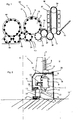
- FIG. 1 shows a schematic representation of a plant for producing plastic containers according to the prior art.
- This system 50 has a heating device 30 in which plastic preforms 10 are heated.
- these plastic preforms 10 are guided by means of a transport device 34, such as a revolving chain, through this heater 30 and thereby heated with a plurality of heating elements 31.
- a transfer unit 36 connects, which the preforms 10th to a sterilization device 32 passes.
- This sterilization device 32 in this case likewise has a transport wheel 37 and sterilizing elements can be arranged on this transport wheel 37 or even stationary. In this area, for example, a sterilization by hydrogen peroxide gas or by electromagnetic radiation is possible. In particular, an internal sterilization of the preforms is carried out in this area.
- the reference numeral 20 denotes in its entirety a clean room, the outer boundaries are indicated here by the dotted line L.
- the clean room 20 is arranged not only in the region of the transport wheel 2 and filling device 40, but possibly already starts in the area of the heating device 30, the sterilization device 32, the plastic preform supply and / or the plastic preform production. It can be seen that this clean room 20 begins in the area of the sterilization unit 32. In this area, lock devices can be provided to introduce the plastic preforms into the clean room 20 without too much gas flowing inside the clean room and thus being lost.
- the clean room is, as indicated by the dashed line L, adapted to the outer shape of the individual plant components. In this way, the volume of the clean room can be reduced.
- the reference numeral 1 denotes in its entirety a forming device in which a plurality of blowing stations or forming stations 8 is arranged on a transport wheel 2, wherein only one of these blowing stations 8 is shown here. With these blowing stations 8, the plastic preforms 10 are expanded to containers 10a. Although not shown in detail here, not the entire area of the transport device 2 is located within the clean room 20, but the clean room 20 or insulator is effectively implemented as a mini-isolator within the entire device. Thus, it would be possible for the clean room to be channel-like, at least in the area of the forming device 1.
- the reference numeral 22 refers to a feeding device which transfers the preforms to the forming device 1 and the reference numeral 24 to a discharge device which discharges the produced plastic containers 20 from the forming device 1. It can be seen that the clean room 20 in the region of the feed device 22 and the discharge device 24 each has recesses which receive these devices 22, 24. In this way, a transfer of the plastic preforms 10 to the forming device 1 and a takeover of the plastic containers 10a of the forming device 1 can be achieved in a particularly advantageous manner.
- the expanded plastic containers are transferred to a filling device 40 and then discharged from this filling device 40 via a further transport unit 44.
- the filling device it would also be possible for the entire filling device 40 with, for example, a reservoir for a beverage, not to be arranged completely inside the clean room 6, but here too only those areas where the containers are actually kept.
- the filling device could be constructed in a similar manner as the device 1 for forming plastic preforms 10th
- the clean room 20 in the area of the device 1 is reduced to a minimum possible area, namely substantially to the blowing stations 8 itself.
- This small-sized design of the clean room 20 makes it easier and faster to produce a clean room at all and also to maintain sterility in the operating phase is less expensive. Also, less sterile air is needed, resulting in smaller filter units and also the risk of uncontrolled vortex formation is reduced.
- FIG. 2 shows a detailed representation of the device 1 in the region of a blowing station 8.
- a plurality of such blowing stations 8 is rotatably moved with a transport device 2 and a support about an axis X.
- the blowing station 8 is as in FIG. 2 can be seen within the clean room 20, which is here channel-like out.
- This clean room 20 is completed by a movable side wall 19 and a lid 17 integrally formed with this side wall 19. This side wall 19 and the cover 17 thereby rotate with the blowing station 8.
- the reference numeral 18 refers to a further wall which limits the clean room 6.
- This wall 18 is here an outer wall, which is arranged stationary.
- a sealing device 25 is provided which the mutually movable elements 17 and 18 against each other seals, for example, as mentioned above, using a moat.
- the lower portion of the wall 18 is fixedly and sealingly arranged on a bottom 13.
- a support 26 is provided, which also moves in rotation and on which in turn a holding device 23 is provided, which holds the blowing station 8.
- the reference numeral 11 refers to a follower which can be actuated by a guide cam 9 to open and close the blow station on its way through the clean room 6, in particular to insert the plastic preform in the blow station and to remove it again.
- a guide curve 9 is also arranged within the clean room 20.
- the transport device 2 may also have further elements, which are arranged above the clean room 20.
- the carrier 26 is fixedly arranged on a holding body 29 and this holding body is in turn movable relative to the bottom 13.
- the reference numeral 27 refers to a further sealing device, which causes a sealing of the mutually movable portions 13 and 29 in this area.
- the reference numeral 5 refers to a stretching rod which is movable with respect to the blowing station in order to stretch the plastic preforms 10 in their longitudinal direction.
- a carriage 12 is arranged on the lid 17, on the other hand, the stretch rod in the direction Y is movable.
- the reference numeral 21 refers to a further holder for this carriage 12 of the stretch rod. 5
- the reference symbol U denotes the (non-sterile) environment of the clean room 20.
- the reference symbol 28 denotes a support for supporting a bottom mold, which also forms part of the blow mold 4. This carrier is also movable in the direction Y.
- the reference numeral 55 refers to a sterilization device, which is preferably arranged here in the interior of the clean room 20 and serves to sterilize the individual transformation stations or components of these conversion stations 8.
- This sterilization device 55 can act on the conversion stations 8, for example, with hydrogen peroxide or other sterilizing agent.
- the sterilization device 55 can be arranged stationary and the transformation stations can move relative to this sterilization device 55.
- This sterilization device or loading device 55 may be located on the transport wheel 2 or on the stationary wall 18 or may be arranged generally stationary and consist of nozzles o similar.
- the blow molds (not shown) are disposed inside the blow mold carriers 6. More precisely, two Blasformabomaschine can be arranged, which are pivotable relative to each other and each holding a blow mold. By this pivoting process, the blow molds for introducing plastic preforms and for removing finished blown containers can be opened. These blow mold carriers and blow molds are likewise arranged inside the clean room.
- the transport device 2 or the carrier has a C-shaped outer circumference, which also partially forms the outer walls of the clean room.
- this C - shaped clean room wall rotates here with the transport device 2, ie the blowing wheel.
- the lower boundary of the clean room is spaced from the floor 13 and moves relative to the floor. In this way, the clean room can be made even smaller than in Fig.2 shown.
- This outer wall is advantageously arranged stationary.
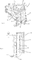
- Fig. 3 shows a perspective view of a blow station 8. This has two Blasformamimaschine 6a and 6b, which are pivotable relative to each other about a pivot axis A, to open the blow mold and close.
- the reference numeral 80 in its entirety denotes a locking mechanism which serves to lock the blow mold halves during expansion of the plastic preforms.
- This locking mechanism 80 has a first locking element 82 and a second locking element 84.
- This first locking element 82 is arranged by means of a first bearing means not shown in detail here pivotally mounted on the second mold support member 66.
- corresponding projections of the first locking element 82 engage in recesses of the second locking element 84.
- This second locking element 84 is non-rotatably arranged on the first mold support part 6a.
- the reference numeral 92 refers to a cam roller which is arranged on a pivot lever 94 and which serves to achieve a pivoting movement of the first locking element 82.
- the two mold carrier parts 6a and 6b are pivotally arranged with respect to a geometric pivot axis A, wherein corresponding bearing devices are also provided for this purpose.
- Fig. 4 denotes a storage device according to the prior art.
- a main shaft 104 is provided here, which can be supplied via a lubricating nipple 106, a lubricant.
- This lubricant passes through a channel 108 and a plurality of secondary channels 112 to the respective bearings 110. In these cases, however, it can lead to leakage of grease, which is undesirable especially in aseptic applications.
- Fig. 5 shows a blowing station according to the invention.
- the two mold carriers 6a, 6b are recognizable and here also the blow molded parts 4a, 4b received by these, which together form the blow mold 4.
- the reference numeral 60 denotes a first bearing means for movably supporting the blow mold parts 6a, 6b.
- Reference numeral 70 denotes a second bearing means for supporting a locking member (not shown).
- Reference numeral 72 denotes a bearing body which will be described in greater detail.
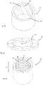
- Fig. 6a shows a possible embodiment of such a bearing body 72.
- This bearing body has in this embodiment, a plurality of grooves 74, which respectively at the Inner wall 75 of the bearing body 72 are arranged.
- the relative to this bearing body 72 to be stored shaft is located within the bearing body 72.
- the grooves 74 extend perpendicular here, ie also along the geometric axis A and B, with respect to the pivoting of the locking element is performed.
- the recesses 74 are configured here as round recesses. In this way, the accumulation of dirt can be counteracted. It is also possible in this way to sterilize along the axis A or B, ie the sterilization agent can also pass through the bearing device 70 or the bearing element 72 with the aid of this recess.
- Fig. 6b shows a further embodiment of a bearing element 72. Again, it is, as in the in Fig. 6a shown embodiment to a thrust bearing. Again, grooves 74 are provided, which do not extend in the longitudinal direction, but obliquely. Also in this way a passage of a sterilizing agent is possible.
- the reference numeral 78 in turn indicates a wall of the bearing element 72nd
- Fig. 6c shows a further embodiment of a bearing element, wherein also here grooves 74a, 74b are provided, which are arranged here on the respective upper and lower surfaces of the bearing element 72. These channels also allow for cleaning agents.
- Fig. 6d shows a further illustration of a bearing element 72. Also in this bearing element here no smooth inner surface 75 is provided, but a plurality of first projections 66 and second projections 68 which each project radially inward. Also between these individual projections 66 and 88 channels 67 are formed, through which also a sterilization medium can flow.
- a first row of the projections 66 is formed here, and in the circumferential direction as well as in the longitudinal direction Lr, in contrast, a second row of second projections 68 is offset. In this way too, a very advantageous design of the bearing body 72 is achieved.
- Fig. 7 shows a further embodiment of a storage device according to the invention.
- a pivot shaft 82 is again provided, which is arranged pivotably with respect to a mold support part 6b.
- the bearing means rolling elements 86, such as needles, which cause the rotating support of the mold support part 6b relative to the shaft 82.
- Reference numeral 88 schematically indicates an injected one Plastic in which these rolling bearings are embedded. This plastic 88 already contains a significant proportion of the lubricant, so that the rotational movement of the rolling elements 86 is lubricated in this way.
- Reference numeral 98 denotes an outer ring of the bearing device which rotates with respect to the shaft 96 as mentioned.
- the plastic it would be possible for the plastic to be a lubricant-containing thermoplastic resin composition which may contain, for example, between 2 and 40 volume percent of a lubricating oil or an oiliness improver.
- This resin composition may additionally contain components, such as a flame retardant, an antistatic agent, an antioxidant or antibacterial agents, such. Silver ions.
- the plastic mass contains between 5 and 25 percent of its total mass or its total volume of the lubricant.
- the proportion of the carrier is between 20% and 40% and preferably about 30% and the proportion of the lubricant accordingly at between 60% and 80% and preferably at about 70%.
- Rolling bearings are therefore preferably used, in which the intermediate spaces are filled with a material that gives the lubrication only to the body, so the rolling bearing itself.
- Fig. 8 shows a further view illustrating the pivotal movement of the mold support part 6b. Again, a plurality of rolling elements embedded in the injected plastic 88 can be seen. In this way, a storage device designed in this way obtains its storage properties substantially over its entire service life.
- Fig. 9 shows a further embodiment of a blowing station and here in particular ways to clean the shaft 96. It should be noted that this embodiment can also be used in conventional blowing stations, ie in particular blowing stations according to the preamble of claim 1 (with or without locking mechanism) , In particular, the in Fig. 9 features shown also with conventional storage facilities can be combined.
- channels 122, 124 are formed in the interior of the shaft, through which one or more (liquid and / or gaseous) cleaning or sterilization media can flow.
- the reference numeral 140 denotes a valve device, here a multi-way valve, via which the shaft at least one cleaning agent and preferably a plurality of cleaning agents can be supplied. More precisely, starting from a first reservoir 145 via a supply line 146, a foam cleaning agent can be supplied to the shaft, starting from a second reservoir 143 via a supply line 144 a sterilizing agent such as peracetic acid or hydrogen peroxide and from a third reservoir 141 via a supply line 142 compressed air Blowing and drying are supplied.
- the device has a valve device 140, via which the supply of at least one cleaning agent or sterilizing agent into the shaft 96 and / or the storage device, advantageously the supply of at least two cleaning or sterilizing agents and particularly preferably the supply of three cleaning or sterilizing agents can be controlled in the storage facility.
- the choice of cleaning or sterilizing agent is preferably made so that the bearing material is damaged as little as possible.
- the reference numeral 152 denotes a further valve element, which is designed here as a check valve and which prevents substances from getting back into the reservoirs 141, 143 and / or 145.
- the respective cleaning or sterilization agent can thus be conducted into a first channel 124 formed in the interior of the shaft 96 and can be brought up to a plain bearing bush 130 of the bearing device 60.
- a second channel formed in the shaft 96 serves to return the cleaning or sterilizing medium. More specifically, the cleaning or sterilizing medium may be discharged via a drain 155 into a collection container 156.
- the reference numeral 154 refers to an optionally providable vacuum pump with which the cleaning agent or residues of the cleaning or sterilizing agent can be removed from the supply line or from the discharge line. Also, a return to the corresponding reservoirs and reuse of the cleaning or sterilizing agent is possible.
- the bearing means 60 and the shaft as known in the art, a lubricant or fat is supplied.
- a lubricant or fat is supplied.
- the same channels which serve to supply the cleaning agent also used for supplying the lubricant.
- the bearing means temporarily (in particular during operation) a lubricant and temporarily (in particular in a cleaning operation) a cleaning agent are supplied.
- the reference numerals 132, 134 relate to optional sealing devices, which delimit the bearing device or the shaft 96 relative to the clean room.
- at least one sealing device is advantageously provided, which is associated with an opening mechanism of Blasformaniis and which shields this opening mechanism of a transport path of the containers.
- sealing means is provided to an unsterile space on at least one of the blow mold terminating components (such as, but not limited to, the impeller, blow mold, or blow mold bottom).
- a sealing device is provided between a drive device of components such as the blowing nozzle, the stretch rod, the mold carrier, a lock, and / or a floor (which drive device is arranged outside the clean room) and the clean room with the individual blow molds ,
- this sealing device could be designed as a bellows.
- This bellows could have a material or be made of a material which contains elastic plastic such as EPDM, Teflon, rubber, elastomers, rubber or steel, membrane bellows or bellows or combinations thereof.
- the sealing device touches the blow mold carrier of two adjacent blow molding stations.
- the sealing device could possibly be welded with metals be.
- the sealing device or the bellows to be arranged partially between the blow mold carrier halves of a blowing station.
- the sealing device could run through an axis of rotation of two mold carrier halves. It would also be possible that two intermeshing waves are used to move the Blasformaniihdonn.
- the locking mechanism for the Blasformizimaschine can also be designed as a pot lock, which is brought, for example, from below or from above to the Blasformizimaschine. It would also be conceivable that such a pot lock is brought from above and a second such pot lock from below to the Blasformizimaschine.
- This pot lock can be, for example, a bottom part of the blow mold or a blowing nozzle (or loading device) arguedendes support member, but can also be carried out independently of the bottom mold or the loading device.
- the blow mold carriers are made of stainless steel and particularly preferably have smooth surfaces. Furthermore, a plastic centering can be provided for the blow mold halves.
- Fig. 9 Cleaning shown for the shaft 96 may also be provided in a corresponding manner for the lever of the blow mold.
- bearings such as stainless steel roller bearings, ceramic roller bearings and / or plastic plain bearings are used.
- the drive devices for moving the loading device, the stretch rod, the blow mold carrier, the latch and / or the bottom part can also be partially or completely executed as electrical and / or magnetic drive means. At least one of these drive devices is advantageously arranged outside the clean room. Also, any combinations of said drive means could be arranged outside of the clean room. In addition, an electrical or magnetic opening of the lock would be conceivable.
- shown embodiment can also be operated in non-aseptic applications, without clean room.
- the mold carrier shaft not like in Fig. 9 is shown outside the clean room, but (at least partially) within the clean room.
- the corresponding storage facilities could be located within the clean room.
Landscapes
- Engineering & Computer Science (AREA)
- Mechanical Engineering (AREA)
- General Engineering & Computer Science (AREA)
- Manufacturing & Machinery (AREA)
- Blow-Moulding Or Thermoforming Of Plastics Or The Like (AREA)
- Moulds For Moulding Plastics Or The Like (AREA)
Claims (10)
- Dispositif de formage par soufflage d'ébauches en matière plastique (10) en récipients en matière plastique (10a) avec une pluralité de postes de soufflage (8) qui sont agencés sur un support mobile (2), dans lequel les postes de soufflage (8) présentent des moules de soufflage (4) présentant respectivement au moins deux pièces de moule de soufflage qui réalisent en leur intérieur un espace creux dans lequel les ébauches en matière plastique (10) peuvent être expansées et dans lequel les postes de soufflage (8) présentent respectivement des dispositifs d'alimentation qui alimentent les ébauches en matière plastique (10) pour leur expansion en un produit coulant, dans lequel les postes de soufflage présentent un mécanisme de verrouillage (80) afin de verrouiller les supports de moule de soufflage (6a, 6b) dans un état fermé l'un avec l'autre et ce mécanisme de verrouillage (80) présente un premier élément de verrouillage (82) ainsi qu'un second élément de verrouillage (84) qui est mobile par rapport au premier élément de verrouillage (82),
caractérisé en ce que
les parties de moule de soufflage sont agencées respectivement sur des supports de moule de soufflage,
les supports de moule de soufflage sont mobiles les uns par rapport aux autres pour l'ouverture et la fermeture du moule de soufflage, et
au moins un premier dispositif de palier (60) pour le logement mobile des supports de moule de soufflage les uns par rapport aux autres et/ou au moins un second dispositif de palier (70) pour le logement mobile du premier élément de verrouillage (82) par rapport au second élément de verrouillage (84) est prévu et au moins un de ces dispositifs de palier (60, 70) est réalisé comme palier lisse sans moyen de lubrification ou comme palier qui est pulvérisé entre des parties de palier mobiles les unes par rapport aux autres au moins partiellement avec une matière plastique. - Dispositif (1) selon la revendication 1,
caractérisé en ce que
le dispositif (1) présente une salle blanche dans laquelle les postes de soufflage sont transportés et cette salle blanche (20) est séparée avec au moins une paroi par rapport à un environnement. - Dispositif (1) selon la revendication 1,
caractérisé en ce que
au moins un support de moule de soufflage (6a, 6b) est agencé de manière pivotante par rapport à un premier axe de pivotement prescrit (A) et le premier dispositif de palier (60) sert de logement à ce mouvement de pivotement. - Dispositif (1) selon la revendication 1,
caractérisé en ce que
au moins un élément de verrouillage (82, 84) est logé de manière pivotante par rapport à un second axe de pivotement (B) et le second dispositif de logement (70) sert au logement de ce mouvement de pivotement par rapport au second axe de pivotement (B). - Dispositif (1) selon au moins l'une des revendications précédentes,
caractérisé en ce que
au moins un dispositif de palier (60, 70) présente sur au moins une surface de palier au moins un évidement (62). - Dispositif (1) selon la revendication 5,
caractérisé en ce que
au moins un dispositif de palier (60, 70) présente une matière plastique comme matériau de palier lisse. - Dispositif (1) selon la revendication 6,
caractérisé en ce que
au moins un matériau d'au moins un dispositif de palier est sélectionné dans un groupe de matières plastiques, en particulier thermoplastiques ou thermodurcissables, ou contient des matériaux métalliques ou des combinaisons de ceux-ci ou similaires. - Dispositif (1) selon la revendication 1,
caractérisé en ce que
dans une matière plastique qui sert de matériau pour au moins un dispositif de palier un lubrifiant pour le dispositif de palier est contenu. - Dispositif (1) selon au moins l'une des revendications précédentes,
caractérisé en ce que
au moins un dispositif de palier sert de palier radial et/ou de palier axial. - Dispositif (1) selon au moins l'une des revendications précédentes,
caractérisé en ce que
au moins un dispositif de palier peut être traversé par un moyen de stérilisation coulant.
Applications Claiming Priority (1)
| Application Number | Priority Date | Filing Date | Title |
|---|---|---|---|
| DE102011106572A DE102011106572A1 (de) | 2011-06-16 | 2011-06-16 | Blasformmaschine mit gleitlagergeführten Schwenkwellen |
Publications (3)
| Publication Number | Publication Date |
|---|---|
| EP2535167A2 EP2535167A2 (fr) | 2012-12-19 |
| EP2535167A3 EP2535167A3 (fr) | 2014-07-30 |
| EP2535167B1 true EP2535167B1 (fr) | 2018-01-10 |
Family
ID=46354030
Family Applications (1)
| Application Number | Title | Priority Date | Filing Date |
|---|---|---|---|
| EP12172380.3A Active EP2535167B1 (fr) | 2011-06-16 | 2012-06-18 | Machine de formage par soufflage avec arbre de pivotement guidé par palier lisse |
Country Status (5)
| Country | Link |
|---|---|
| US (1) | US8684716B2 (fr) |
| EP (1) | EP2535167B1 (fr) |
| JP (1) | JP2013001120A (fr) |
| CN (1) | CN102825775B (fr) |
| DE (1) | DE102011106572A1 (fr) |
Families Citing this family (9)
| Publication number | Priority date | Publication date | Assignee | Title |
|---|---|---|---|---|
| CN103171136B (zh) * | 2013-03-19 | 2015-05-20 | 江苏新美星包装机械股份有限公司 | 一种底模升降、双边定位联动机构 |
| CN103171141B (zh) * | 2013-03-19 | 2015-08-26 | 江苏新美星包装机械股份有限公司 | 一种底模的升降机构 |
| CN103171137B (zh) * | 2013-03-19 | 2015-02-11 | 江苏新美星包装机械股份有限公司 | 一种底模升降、单边锁定联动机构 |
| DE102013218337A1 (de) | 2013-09-12 | 2015-03-12 | Krones Aktiengesellschaft | Transporteinrichtung und Verfahren zum Transport von Kunststoffbehältnissen oder Vorformlingen |
| WO2017059930A1 (fr) * | 2015-10-09 | 2017-04-13 | Krones Ag | Dispositif de moulage par soufflage présentant un accouplement de fond à actionnement automatique et procédé pour le fonctionnement du dispositif associé |
| IT201800002781A1 (it) * | 2018-02-16 | 2019-08-16 | Gea Procomac Spa | Dispositivo di stiro-soffiaggio in asettico per una preforma in materiale termoplastico |
| CN108869549A (zh) * | 2018-04-11 | 2018-11-23 | 启东海大聚龙新材料科技有限公司 | 一种多层耐磨材料及其制备方法与应用 |
| IT201800005081A1 (it) * | 2018-05-04 | 2019-11-04 | Apparato di imbottigliamento in asettico di contenitori in materiale termoplastico | |
| DE102020123163A1 (de) * | 2020-09-04 | 2022-03-10 | Krones Aktiengesellschaft | Vorrichtung und Verfahren zum Erwärmen von Kunststoffvorformlingen mit ortaufgelöster Temperaturerfassung |
Family Cites Families (19)
| Publication number | Priority date | Publication date | Assignee | Title |
|---|---|---|---|---|
| GB798378A (en) * | 1955-04-23 | 1958-07-16 | Bound Brook Bearings Ltd | Improvements in porous metal journal bearings |
| US3896036A (en) * | 1969-03-17 | 1975-07-22 | Garlock Inc | Bearing compositions |
| US4208852A (en) * | 1974-11-08 | 1980-06-24 | Pont-A-Mousson S.A. | Process for the aseptic packing of products and machine employing said process |
| JPS5590318A (en) * | 1978-12-28 | 1980-07-08 | Yoshino Kogyosho Co Ltd | Heat rolling blow molding apparatus |
| GB2235736B (en) * | 1989-08-09 | 1993-09-15 | Nippon Seiko Kk | Bearing with dynamic pressure grooves and method for manufacturing the same |
| JP2586744Y2 (ja) * | 1993-08-25 | 1998-12-09 | 株式会社千代田製作所 | マグネットカップリング装置 |
| JP3365449B2 (ja) * | 1994-07-07 | 2003-01-14 | 日本精工株式会社 | 転がり軸受 |
| WO1997025544A1 (fr) * | 1996-01-04 | 1997-07-17 | Small Enterprise 'fan' | Procede de fabrication de paliers a roulement possedant un joint a labyrinthe |
| US5698241A (en) * | 1996-08-19 | 1997-12-16 | Plastipak Packaging, Inc. | Rotary plastic blow molding machine |
| JP2000145786A (ja) * | 1998-11-05 | 2000-05-26 | Nippon Petrochem Co Ltd | 樹脂製ベアリングおよびその製造方法 |
| FR2793722B1 (fr) * | 1999-05-17 | 2001-08-03 | Sidel Sa | Machine de soufflage comportant un mecanisme de fermeture et de verrouillage combines d'une unite de moulage |
| DE10354506A1 (de) * | 2003-11-21 | 2005-06-09 | Sig Technology Ltd. | Vorrichtung zur Blasformung von Behältern |
| JP5456960B2 (ja) * | 2007-09-25 | 2014-04-02 | 株式会社リコー | 現像装置、画像形成装置 |
| DE102008038141B4 (de) | 2008-08-18 | 2025-03-13 | Krones Aktiengesellschaft | Vorrichtung mit Reinraum zum Umformen von Kunststoffvorformlingen zu Kunststoffbehältnissen und Anlage zum Herstellen von Kunststoffbehältnissen sowie Verfahren zum Umformen von Kunststoffvorformlingen zu Kunststoffbehältnissen |
| DE102008060759A1 (de) * | 2008-12-05 | 2010-06-10 | Schaeffler Kg | Führungsschiene einer Laufrollenführung |
| DE102008063939A1 (de) * | 2008-12-19 | 2010-07-01 | Krones Ag | Blasform |
| EP2263854B1 (fr) * | 2008-12-19 | 2013-05-01 | Krones AG | Machine de formage par soufflage entraînée de manière électrique et le procédé |
| DE102009040559A1 (de) * | 2009-09-08 | 2011-03-10 | Krones Ag | Verfahren und Vorrichtung zum Blasformen von Behältern |
| DE102011013126A1 (de) * | 2011-03-04 | 2012-09-06 | Krones Aktiengesellschaft | Blasmaschine mit Blasformverriegelung im Reinraum |
-
2011
- 2011-06-16 DE DE102011106572A patent/DE102011106572A1/de not_active Ceased
-
2012
- 2012-06-05 US US13/489,292 patent/US8684716B2/en active Active
- 2012-06-13 JP JP2012133850A patent/JP2013001120A/ja active Pending
- 2012-06-15 CN CN201210201921.5A patent/CN102825775B/zh active Active
- 2012-06-18 EP EP12172380.3A patent/EP2535167B1/fr active Active
Non-Patent Citations (1)
| Title |
|---|
| None * |
Also Published As
| Publication number | Publication date |
|---|---|
| CN102825775A (zh) | 2012-12-19 |
| JP2013001120A (ja) | 2013-01-07 |
| EP2535167A3 (fr) | 2014-07-30 |
| US8684716B2 (en) | 2014-04-01 |
| CN102825775B (zh) | 2014-10-15 |
| EP2535167A2 (fr) | 2012-12-19 |
| DE102011106572A1 (de) | 2012-12-20 |
| US20120321741A1 (en) | 2012-12-20 |
Similar Documents
| Publication | Publication Date | Title |
|---|---|---|
| EP2535167B1 (fr) | Machine de formage par soufflage avec arbre de pivotement guidé par palier lisse | |
| EP2388127B1 (fr) | Dispositif de déformation d'ébauches en matière synthétique dotées d'un espace stérile | |
| EP2848387B1 (fr) | Machine de moulage par soufflage avec une valve de soufflage pneumatique, et méthode de mise en oeuvre d'une telle machine. | |
| EP2511070B1 (fr) | Dispositif et procédé de transformation de préformes en matière synthétique en récipients en plastique avec mouvements couplés de verrouillage et d'oscillation | |
| EP2848384B1 (fr) | Dispositif de transformation de préformes en matière synthétique avec salle blanche | |
| EP2709820B1 (fr) | Procédé et appareil pour la fabrication de recipients remplis à partir de préformes | |
| DE102011013126A1 (de) | Blasmaschine mit Blasformverriegelung im Reinraum | |
| EP2537662B1 (fr) | Dispositif et procédé de transformation d'ébauches en matière synthétique pour devenir des conteneurs en plastique avec mouvements de tige d'étirage étanches | |
| EP2522485B1 (fr) | Machine et procédé de formage par soufflage aseptique avec évacuation stérile de l'air, ainsi que moule de soufflage | |
| EP2495090B1 (fr) | Souffleuse dotée d'une chambre stérile et d'une entrée de fluides dans la chambre stérile | |
| EP2570251B1 (fr) | Souffleuse avec stations de soufflage démontables | |
| EP2695721B1 (fr) | Dispositif d'étanchéité avec possibilité de compensation pour plusieurs directions de mouvement | |
| EP2913174B1 (fr) | Machine de formage par soufflage à centrage du fond de moule de soufflage | |
| EP2777912B1 (fr) | Dispositif de traitement de récipients comprenant des galets de guidage en matière synthétique en polyamidimide | |
| DE102013015093A1 (de) | Vorrichtung zum Umformen von Kunststoffvorformlingen zu Kunststoffbehältnissen sowie Blasformträger | |
| DE202013104120U1 (de) | Vorrichtung zum Umformen von Kunststoffvorformlingen zu Kunststoffbehältnissen mit asymmetrischer Blasformöffnungsbewegung | |
| EP3678835B1 (fr) | Station de moulage et remplisage | |
| EP2735428A1 (fr) | Procédé d'étirage-soufflage et machine d'étirage-soufflage | |
| EP2495091B1 (fr) | Machine de moulage par soufflage dotée d'une chambre stérile et d'une entrée d'air de soufflage stérile | |
| EP4299280B1 (fr) | Dispositif et procédé de déformation d'ébauches en plastique en récipients en plastique | |
| DE202013008081U1 (de) | Vorrichtung zum Umformen von Kunststoffvorformlingen zu Kunststoffbehältnissen sowie Blasformträger | |
| WO2018224479A1 (fr) | Ensemble moule de soufflage servant à transformer des préformes en matière plastique en contenants en matière plastique comportant des éléments de déviation de force et un procédé dédié à cet effet et un dispositif servant à transformer des préformes en matière plastique comportant un dispositif de verrouillage | |
| DE102014018144A1 (de) | Blasformmaschine mit Zentrierung des Blasformbodens | |
| DE202014105296U1 (de) | Blasformmaschine mit Gleitlagern zur Blasformträgerbewegung |
Legal Events
| Date | Code | Title | Description |
|---|---|---|---|
| PUAI | Public reference made under article 153(3) epc to a published international application that has entered the european phase |
Free format text: ORIGINAL CODE: 0009012 |
|
| AK | Designated contracting states |
Kind code of ref document: A2 Designated state(s): AL AT BE BG CH CY CZ DE DK EE ES FI FR GB GR HR HU IE IS IT LI LT LU LV MC MK MT NL NO PL PT RO RS SE SI SK SM TR |
|
| AX | Request for extension of the european patent |
Extension state: BA ME |
|
| PUAL | Search report despatched |
Free format text: ORIGINAL CODE: 0009013 |
|
| AK | Designated contracting states |
Kind code of ref document: A3 Designated state(s): AL AT BE BG CH CY CZ DE DK EE ES FI FR GB GR HR HU IE IS IT LI LT LU LV MC MK MT NL NO PL PT RO RS SE SI SK SM TR |
|
| AX | Request for extension of the european patent |
Extension state: BA ME |
|
| RIC1 | Information provided on ipc code assigned before grant |
Ipc: B29C 49/56 20060101ALI20140620BHEP Ipc: B29C 49/06 20060101ALI20140620BHEP Ipc: F16C 33/46 20060101ALI20140620BHEP Ipc: B29C 49/36 20060101ALI20140620BHEP Ipc: F16C 33/20 20060101ALI20140620BHEP Ipc: B29C 49/46 20060101AFI20140620BHEP Ipc: F16C 33/56 20060101ALI20140620BHEP |
|
| 17P | Request for examination filed |
Effective date: 20150109 |
|
| RBV | Designated contracting states (corrected) |
Designated state(s): AL AT BE BG CH CY CZ DE DK EE ES FI FR GB GR HR HU IE IS IT LI LT LU LV MC MK MT NL NO PL PT RO RS SE SI SK SM TR |
|
| GRAP | Despatch of communication of intention to grant a patent |
Free format text: ORIGINAL CODE: EPIDOSNIGR1 |
|
| INTG | Intention to grant announced |
Effective date: 20170622 |
|
| GRAS | Grant fee paid |
Free format text: ORIGINAL CODE: EPIDOSNIGR3 |
|
| RIN1 | Information on inventor provided before grant (corrected) |
Inventor name: GELTINGER, FLORIAN Inventor name: MARTINI, OLIVER Inventor name: HAUSLADEN, JOSEF Inventor name: WINZINGER, FRANK Inventor name: SOELLNER, JUERGEN Inventor name: NEUBAUER, MICHAEL Inventor name: VOTH, KLAUS Inventor name: LAPPE, ULRICH |
|
| RIN1 | Information on inventor provided before grant (corrected) |
Inventor name: NEUBAUER, MICHAEL Inventor name: WINZINGER, FRANK Inventor name: VOTH, KLAUS Inventor name: LAPPE, ULRICH Inventor name: HAUSLADEN, JOSEF Inventor name: GELTINGER, FLORIAN Inventor name: SOELLNER, JUERGEN Inventor name: MARTINI, OLIVER |
|
| GRAA | (expected) grant |
Free format text: ORIGINAL CODE: 0009210 |
|
| AK | Designated contracting states |
Kind code of ref document: B1 Designated state(s): AL AT BE BG CH CY CZ DE DK EE ES FI FR GB GR HR HU IE IS IT LI LT LU LV MC MK MT NL NO PL PT RO RS SE SI SK SM TR |
|
| REG | Reference to a national code |
Ref country code: GB Ref legal event code: FG4D Free format text: NOT ENGLISH |
|
| REG | Reference to a national code |
Ref country code: CH Ref legal event code: EP Ref country code: AT Ref legal event code: REF Ref document number: 961896 Country of ref document: AT Kind code of ref document: T Effective date: 20180115 |
|
| REG | Reference to a national code |
Ref country code: IE Ref legal event code: FG4D Free format text: LANGUAGE OF EP DOCUMENT: GERMAN |
|
| REG | Reference to a national code |
Ref country code: DE Ref legal event code: R096 Ref document number: 502012011997 Country of ref document: DE |
|
| REG | Reference to a national code |
Ref country code: FR Ref legal event code: PLFP Year of fee payment: 7 |
|
| REG | Reference to a national code |
Ref country code: NL Ref legal event code: MP Effective date: 20180110 |
|
| PG25 | Lapsed in a contracting state [announced via postgrant information from national office to epo] |
Ref country code: NL Free format text: LAPSE BECAUSE OF FAILURE TO SUBMIT A TRANSLATION OF THE DESCRIPTION OR TO PAY THE FEE WITHIN THE PRESCRIBED TIME-LIMIT Effective date: 20180110 |
|
| PG25 | Lapsed in a contracting state [announced via postgrant information from national office to epo] |
Ref country code: LT Free format text: LAPSE BECAUSE OF FAILURE TO SUBMIT A TRANSLATION OF THE DESCRIPTION OR TO PAY THE FEE WITHIN THE PRESCRIBED TIME-LIMIT Effective date: 20180110 Ref country code: CY Free format text: LAPSE BECAUSE OF FAILURE TO SUBMIT A TRANSLATION OF THE DESCRIPTION OR TO PAY THE FEE WITHIN THE PRESCRIBED TIME-LIMIT Effective date: 20180110 Ref country code: FI Free format text: LAPSE BECAUSE OF FAILURE TO SUBMIT A TRANSLATION OF THE DESCRIPTION OR TO PAY THE FEE WITHIN THE PRESCRIBED TIME-LIMIT Effective date: 20180110 Ref country code: NO Free format text: LAPSE BECAUSE OF FAILURE TO SUBMIT A TRANSLATION OF THE DESCRIPTION OR TO PAY THE FEE WITHIN THE PRESCRIBED TIME-LIMIT Effective date: 20180410 Ref country code: ES Free format text: LAPSE BECAUSE OF FAILURE TO SUBMIT A TRANSLATION OF THE DESCRIPTION OR TO PAY THE FEE WITHIN THE PRESCRIBED TIME-LIMIT Effective date: 20180110 Ref country code: HR Free format text: LAPSE BECAUSE OF FAILURE TO SUBMIT A TRANSLATION OF THE DESCRIPTION OR TO PAY THE FEE WITHIN THE PRESCRIBED TIME-LIMIT Effective date: 20180110 |
|
| PG25 | Lapsed in a contracting state [announced via postgrant information from national office to epo] |
Ref country code: SE Free format text: LAPSE BECAUSE OF FAILURE TO SUBMIT A TRANSLATION OF THE DESCRIPTION OR TO PAY THE FEE WITHIN THE PRESCRIBED TIME-LIMIT Effective date: 20180110 Ref country code: LV Free format text: LAPSE BECAUSE OF FAILURE TO SUBMIT A TRANSLATION OF THE DESCRIPTION OR TO PAY THE FEE WITHIN THE PRESCRIBED TIME-LIMIT Effective date: 20180110 Ref country code: RS Free format text: LAPSE BECAUSE OF FAILURE TO SUBMIT A TRANSLATION OF THE DESCRIPTION OR TO PAY THE FEE WITHIN THE PRESCRIBED TIME-LIMIT Effective date: 20180110 Ref country code: BG Free format text: LAPSE BECAUSE OF FAILURE TO SUBMIT A TRANSLATION OF THE DESCRIPTION OR TO PAY THE FEE WITHIN THE PRESCRIBED TIME-LIMIT Effective date: 20180410 Ref country code: IS Free format text: LAPSE BECAUSE OF FAILURE TO SUBMIT A TRANSLATION OF THE DESCRIPTION OR TO PAY THE FEE WITHIN THE PRESCRIBED TIME-LIMIT Effective date: 20180510 Ref country code: PL Free format text: LAPSE BECAUSE OF FAILURE TO SUBMIT A TRANSLATION OF THE DESCRIPTION OR TO PAY THE FEE WITHIN THE PRESCRIBED TIME-LIMIT Effective date: 20180110 Ref country code: GR Free format text: LAPSE BECAUSE OF FAILURE TO SUBMIT A TRANSLATION OF THE DESCRIPTION OR TO PAY THE FEE WITHIN THE PRESCRIBED TIME-LIMIT Effective date: 20180411 |
|
| PG25 | Lapsed in a contracting state [announced via postgrant information from national office to epo] |
Ref country code: MT Free format text: LAPSE BECAUSE OF FAILURE TO SUBMIT A TRANSLATION OF THE DESCRIPTION OR TO PAY THE FEE WITHIN THE PRESCRIBED TIME-LIMIT Effective date: 20180110 |
|
| REG | Reference to a national code |
Ref country code: DE Ref legal event code: R097 Ref document number: 502012011997 Country of ref document: DE |
|
| PG25 | Lapsed in a contracting state [announced via postgrant information from national office to epo] |
Ref country code: RO Free format text: LAPSE BECAUSE OF FAILURE TO SUBMIT A TRANSLATION OF THE DESCRIPTION OR TO PAY THE FEE WITHIN THE PRESCRIBED TIME-LIMIT Effective date: 20180110 Ref country code: EE Free format text: LAPSE BECAUSE OF FAILURE TO SUBMIT A TRANSLATION OF THE DESCRIPTION OR TO PAY THE FEE WITHIN THE PRESCRIBED TIME-LIMIT Effective date: 20180110 Ref country code: AL Free format text: LAPSE BECAUSE OF FAILURE TO SUBMIT A TRANSLATION OF THE DESCRIPTION OR TO PAY THE FEE WITHIN THE PRESCRIBED TIME-LIMIT Effective date: 20180110 |
|
| PLBE | No opposition filed within time limit |
Free format text: ORIGINAL CODE: 0009261 |
|
| STAA | Information on the status of an ep patent application or granted ep patent |
Free format text: STATUS: NO OPPOSITION FILED WITHIN TIME LIMIT |
|
| PG25 | Lapsed in a contracting state [announced via postgrant information from national office to epo] |
Ref country code: SM Free format text: LAPSE BECAUSE OF FAILURE TO SUBMIT A TRANSLATION OF THE DESCRIPTION OR TO PAY THE FEE WITHIN THE PRESCRIBED TIME-LIMIT Effective date: 20180110 Ref country code: DK Free format text: LAPSE BECAUSE OF FAILURE TO SUBMIT A TRANSLATION OF THE DESCRIPTION OR TO PAY THE FEE WITHIN THE PRESCRIBED TIME-LIMIT Effective date: 20180110 Ref country code: SK Free format text: LAPSE BECAUSE OF FAILURE TO SUBMIT A TRANSLATION OF THE DESCRIPTION OR TO PAY THE FEE WITHIN THE PRESCRIBED TIME-LIMIT Effective date: 20180110 Ref country code: CZ Free format text: LAPSE BECAUSE OF FAILURE TO SUBMIT A TRANSLATION OF THE DESCRIPTION OR TO PAY THE FEE WITHIN THE PRESCRIBED TIME-LIMIT Effective date: 20180110 |
|
| 26N | No opposition filed |
Effective date: 20181011 |
|
| REG | Reference to a national code |
Ref country code: CH Ref legal event code: PL |
|
| GBPC | Gb: european patent ceased through non-payment of renewal fee |
Effective date: 20180618 |
|
| PG25 | Lapsed in a contracting state [announced via postgrant information from national office to epo] |
Ref country code: SI Free format text: LAPSE BECAUSE OF FAILURE TO SUBMIT A TRANSLATION OF THE DESCRIPTION OR TO PAY THE FEE WITHIN THE PRESCRIBED TIME-LIMIT Effective date: 20180110 |
|
| REG | Reference to a national code |
Ref country code: BE Ref legal event code: MM Effective date: 20180630 |
|
| REG | Reference to a national code |
Ref country code: IE Ref legal event code: MM4A |
|
| PG25 | Lapsed in a contracting state [announced via postgrant information from national office to epo] |
Ref country code: MC Free format text: LAPSE BECAUSE OF FAILURE TO SUBMIT A TRANSLATION OF THE DESCRIPTION OR TO PAY THE FEE WITHIN THE PRESCRIBED TIME-LIMIT Effective date: 20180110 Ref country code: LU Free format text: LAPSE BECAUSE OF NON-PAYMENT OF DUE FEES Effective date: 20180618 |
|
| PG25 | Lapsed in a contracting state [announced via postgrant information from national office to epo] |
Ref country code: IE Free format text: LAPSE BECAUSE OF NON-PAYMENT OF DUE FEES Effective date: 20180618 Ref country code: CH Free format text: LAPSE BECAUSE OF NON-PAYMENT OF DUE FEES Effective date: 20180630 Ref country code: LI Free format text: LAPSE BECAUSE OF NON-PAYMENT OF DUE FEES Effective date: 20180630 Ref country code: GB Free format text: LAPSE BECAUSE OF NON-PAYMENT OF DUE FEES Effective date: 20180618 |
|
| PG25 | Lapsed in a contracting state [announced via postgrant information from national office to epo] |
Ref country code: BE Free format text: LAPSE BECAUSE OF NON-PAYMENT OF DUE FEES Effective date: 20180630 |
|
| REG | Reference to a national code |
Ref country code: AT Ref legal event code: MM01 Ref document number: 961896 Country of ref document: AT Kind code of ref document: T Effective date: 20180618 |
|
| PG25 | Lapsed in a contracting state [announced via postgrant information from national office to epo] |
Ref country code: AT Free format text: LAPSE BECAUSE OF NON-PAYMENT OF DUE FEES Effective date: 20180618 |
|
| PG25 | Lapsed in a contracting state [announced via postgrant information from national office to epo] |
Ref country code: TR Free format text: LAPSE BECAUSE OF FAILURE TO SUBMIT A TRANSLATION OF THE DESCRIPTION OR TO PAY THE FEE WITHIN THE PRESCRIBED TIME-LIMIT Effective date: 20180110 |
|
| PG25 | Lapsed in a contracting state [announced via postgrant information from national office to epo] |
Ref country code: PT Free format text: LAPSE BECAUSE OF FAILURE TO SUBMIT A TRANSLATION OF THE DESCRIPTION OR TO PAY THE FEE WITHIN THE PRESCRIBED TIME-LIMIT Effective date: 20180110 Ref country code: HU Free format text: LAPSE BECAUSE OF FAILURE TO SUBMIT A TRANSLATION OF THE DESCRIPTION OR TO PAY THE FEE WITHIN THE PRESCRIBED TIME-LIMIT; INVALID AB INITIO Effective date: 20120618 |
|
| PG25 | Lapsed in a contracting state [announced via postgrant information from national office to epo] |
Ref country code: MK Free format text: LAPSE BECAUSE OF NON-PAYMENT OF DUE FEES Effective date: 20180110 |
|
| P01 | Opt-out of the competence of the unified patent court (upc) registered |
Effective date: 20230523 |
|
| PGFP | Annual fee paid to national office [announced via postgrant information from national office to epo] |
Ref country code: DE Payment date: 20250429 Year of fee payment: 14 |
|
| PGFP | Annual fee paid to national office [announced via postgrant information from national office to epo] |
Ref country code: IT Payment date: 20250522 Year of fee payment: 14 |
|
| PGFP | Annual fee paid to national office [announced via postgrant information from national office to epo] |
Ref country code: FR Payment date: 20250508 Year of fee payment: 14 |