EP3678835B1 - Station de moulage et remplisage - Google Patents
Station de moulage et remplisage Download PDFInfo
- Publication number
- EP3678835B1 EP3678835B1 EP18765875.2A EP18765875A EP3678835B1 EP 3678835 B1 EP3678835 B1 EP 3678835B1 EP 18765875 A EP18765875 A EP 18765875A EP 3678835 B1 EP3678835 B1 EP 3678835B1
- Authority
- EP
- European Patent Office
- Prior art keywords
- pressure
- mould filling
- low
- gap
- filling station
- Prior art date
- Legal status (The legal status is an assumption and is not a legal conclusion. Google has not performed a legal analysis and makes no representation as to the accuracy of the status listed.)
- Active
Links
Images

Classifications
-
- B—PERFORMING OPERATIONS; TRANSPORTING
- B29—WORKING OF PLASTICS; WORKING OF SUBSTANCES IN A PLASTIC STATE IN GENERAL
- B29C—SHAPING OR JOINING OF PLASTICS; SHAPING OF MATERIAL IN A PLASTIC STATE, NOT OTHERWISE PROVIDED FOR; AFTER-TREATMENT OF THE SHAPED PRODUCTS, e.g. REPAIRING
- B29C49/00—Blow-moulding, i.e. blowing a preform or parison to a desired shape within a mould; Apparatus therefor
- B29C49/08—Biaxial stretching during blow-moulding
- B29C49/10—Biaxial stretching during blow-moulding using mechanical means for prestretching
- B29C49/12—Stretching rods
-
- B—PERFORMING OPERATIONS; TRANSPORTING
- B29—WORKING OF PLASTICS; WORKING OF SUBSTANCES IN A PLASTIC STATE IN GENERAL
- B29C—SHAPING OR JOINING OF PLASTICS; SHAPING OF MATERIAL IN A PLASTIC STATE, NOT OTHERWISE PROVIDED FOR; AFTER-TREATMENT OF THE SHAPED PRODUCTS, e.g. REPAIRING
- B29C49/00—Blow-moulding, i.e. blowing a preform or parison to a desired shape within a mould; Apparatus therefor
- B29C49/02—Combined blow-moulding and manufacture of the preform or the parison
- B29C49/06—Injection blow-moulding
-
- B—PERFORMING OPERATIONS; TRANSPORTING
- B29—WORKING OF PLASTICS; WORKING OF SUBSTANCES IN A PLASTIC STATE IN GENERAL
- B29C—SHAPING OR JOINING OF PLASTICS; SHAPING OF MATERIAL IN A PLASTIC STATE, NOT OTHERWISE PROVIDED FOR; AFTER-TREATMENT OF THE SHAPED PRODUCTS, e.g. REPAIRING
- B29C49/00—Blow-moulding, i.e. blowing a preform or parison to a desired shape within a mould; Apparatus therefor
- B29C49/02—Combined blow-moulding and manufacture of the preform or the parison
- B29C2049/023—Combined blow-moulding and manufacture of the preform or the parison using inherent heat of the preform, i.e. 1 step blow moulding
-
- B—PERFORMING OPERATIONS; TRANSPORTING
- B29—WORKING OF PLASTICS; WORKING OF SUBSTANCES IN A PLASTIC STATE IN GENERAL
- B29C—SHAPING OR JOINING OF PLASTICS; SHAPING OF MATERIAL IN A PLASTIC STATE, NOT OTHERWISE PROVIDED FOR; AFTER-TREATMENT OF THE SHAPED PRODUCTS, e.g. REPAIRING
- B29C49/00—Blow-moulding, i.e. blowing a preform or parison to a desired shape within a mould; Apparatus therefor
- B29C49/42—Component parts, details or accessories; Auxiliary operations
- B29C2049/4294—Sealing means
-
- B—PERFORMING OPERATIONS; TRANSPORTING
- B29—WORKING OF PLASTICS; WORKING OF SUBSTANCES IN A PLASTIC STATE IN GENERAL
- B29C—SHAPING OR JOINING OF PLASTICS; SHAPING OF MATERIAL IN A PLASTIC STATE, NOT OTHERWISE PROVIDED FOR; AFTER-TREATMENT OF THE SHAPED PRODUCTS, e.g. REPAIRING
- B29C49/00—Blow-moulding, i.e. blowing a preform or parison to a desired shape within a mould; Apparatus therefor
- B29C49/42—Component parts, details or accessories; Auxiliary operations
- B29C49/46—Component parts, details or accessories; Auxiliary operations characterised by using particular environment or blow fluids other than air
- B29C2049/4602—Blowing fluids
- B29C2049/465—Blowing fluids being incompressible
- B29C2049/4664—Blowing fluids being incompressible staying in the final article
-
- B—PERFORMING OPERATIONS; TRANSPORTING
- B29—WORKING OF PLASTICS; WORKING OF SUBSTANCES IN A PLASTIC STATE IN GENERAL
- B29C—SHAPING OR JOINING OF PLASTICS; SHAPING OF MATERIAL IN A PLASTIC STATE, NOT OTHERWISE PROVIDED FOR; AFTER-TREATMENT OF THE SHAPED PRODUCTS, e.g. REPAIRING
- B29C49/00—Blow-moulding, i.e. blowing a preform or parison to a desired shape within a mould; Apparatus therefor
- B29C49/42—Component parts, details or accessories; Auxiliary operations
- B29C49/58—Blowing means
Definitions
- the invention relates to a mold filling device according to the preamble of claim 1.
- the manufacture of containers by blow molding from preforms made of a thermoplastic material for example from preforms made of PET (polyethylene terephthalate), is known, the preforms being fed to different processing stations within a blow molding machine ( DE 4340291 A1 ).
- a blow molding machine has a heating device for tempering or for thermal conditioning of the preforms and a blow molding device with at least one blow molding station, in the area of which the previously tempered preform is expanded to form a container.
- the expansion takes place with the aid of a compressed gas (compressed air) as a pressure medium, which is introduced into the preform to be expanded with a molding pressure.
- the procedural sequence in such an expansion of the preform is in the DE 4340291 A1 explained.
- the basic structure of a blow molding station is DE 4212583 A1 described. Possibilities of tempering the preforms are in DE 2352926 A1 explained.
- Temperature control or thermal conditioning is understood to mean that the preform is heated to a temperature suitable for blow molding and, if necessary, a temperature profile is impressed on the preform.
- the blow molding of containers from preforms with the additional use of a stretch rod is also known.
- the EP 1 258 336 A1 and the EP 2 540 473 A2 show further examples of blow molding machines in which preforms are expanded into containers with the help of compressed gas.
- the DE 10 2013 110 088 A1 discloses a pneumatically actuated blown air valve used in a blow molding machine as explained in the preceding paragraph, namely for controlling the supply of blown air.
- a control piston is moveable in movable and sealed form within a control chamber of the valve.
- the control chamber is intended to be acted upon by a control fluid in order to control the movement of the control piston.
- the various chambers and spaces are sealed on the one hand by a membrane body, which divides the control chamber into 2 sub-chambers, namely a first sub-chamber in which the control piston is located and a second sub-chamber in which the control piston is not located.
- the control piston has an annular seal so that it can be moved in a sealed manner relative to the cylindrical inner wall of the first sub-chamber in order to further subdivide this first sub-chamber into a sub-chamber close to the diaphragm and a sub-chamber distant from the diaphragm.
- another seal is provided, which separates the working space, which is acted upon by blown air, from the control chamber, which is acted upon by a control fluid.
- the working piston of the valve which is driven by the control piston, is guided through this seal.
- the containers produced by blow molding are fed to a subsequent filling device and filled here with the intended product or filling.
- a separate blow molding machine and a separate filling machine are therefore used. It is also known to combine the separate blow molding machine and the separate filling machine into one machine block, i.e. into one block blow-fill device, with blow molding and filling still being carried out on separate machine components and one after the other.
- the containers are formed from the preforms by the filling material itself, ie using the filling material as the hydraulic pressure medium, only one machine is required for forming and filling the containers, but this machine is more complex.
- An example of such a machine is shown in US7914726B2 .
- Another example shows the DE 2010007541 A1 .
- a third and fourth example are shown in the DE 10 2014 017 871 A1 and the DE 10 2014 016 140 A1 .
- An important principle in the form and fill process is the guarantee of absolute cleanliness in all areas of the form filling stations that come into contact with the filling material. Even small amounts of contamination from the area surrounding the mold filling station or from gaps within the mold filling station that come into contact with the filling material can lead to contamination of the filling material and thus to the filled products being unusable. Especially when filling liquids containing sugar, there is a particular risk that residues of filling material left in gaps in the mold filling station will trigger mold or fungus growth if they come into contact with microorganisms originating from the area surrounding the mold filling stations. The gaps in the mold filling stations are therefore flushed at regular intervals and any residues of the product are removed.
- the problem is that contaminants and microorganisms from the environment can also come into contact with the mold filling station between the cleaning processes, ie in particular during the filling of the filling material.
- the mold filling stations of the filling device can be subjected to an air curtain, for example. This forms a gas barrier layer that keeps contaminants out of the area around the mold filling stations.
- a continuing motivation in the further development of known mold filling devices of the generic type is to improve the previously known protective options for sealing off sensitive working areas of the mold filling device and in particular for protecting narrow gaps in the filling station from contamination.
- the protection of the filling stations is very difficult, especially in the area of moving body parts, since the protective measures must be effective even at high relative speeds and with large displacement distances between moving parts.
- the invention is therefore based on the object of providing a filling device with filling stations which offers improved protection of the filling material against contamination at high forming and filling speeds.
- a mold filling device for producing containers filled with a liquid filling material from thermally conditioned preforms, with at least one mold filling station for molding and filling a preform, wherein the mold filling station has a longitudinally displaceable stretching rod for guiding and stretching the preform, and wherein the mold filling station has at least one Gap space between two mutually displaceably mounted body parts of the mold filling station, in a position of use of the mold filling station is separated by means of a gap seal acting on a surface of one of the body parts into a high-pressure area and a low-pressure area, with the high-pressure area being able to be connected in a communicating manner to the interior of the preform and the low-pressure area being connected by means of a flexible, sealingly connected to the body parts that are movable in relation to one another sealing membrane is sealed.
- the gap that can be connected to the interior of the preform at a filling nozzle is filled with the filling material to be filled. Because of the high filling pressure, which can be in the range of up to 35 bar or more than 35 bar, this area is also referred to as the high-pressure area.
- the high-pressure area can be connected to a reservoir in a manner that is not explained in detail.
- a gap seal seals on a surface of one or both of the moving body parts.
- a sealing membrane is connected to the two body parts in a force-fitting and/or material-locking manner at its edge regions, so that a hermetically sealed connection is created between the body parts.
- gap seals are understood to mean both seals that seal slidingly on the surface, ie touch the surface of the sealing partner, and seals that interact with the surface of the sealing partner in a non-contact sealing manner.
- Sealing membranes according to the invention can in particular be designed in the manner of a bellows seal.
- Non-contact gap seals can be designed, for example, as throttle bushings or throttle seals, with such throttle seals being able to be designed in particular as a floating ring throttle or end gap throttle.
- Gap seals that seal in contact can be formed, for example, from sealing rings.
- Non-contact seals are the preferred type of seal for sealing the moving parts of the mold filling station because they are particularly useful for sealing body parts that move at very high relative speeds. Unlike contact seals, there is no high friction and no heavy wear.
- the structure and mode of operation of non-contact gap seals such as throttle bushings are known from the prior art, so that a detailed explanation can be dispensed with.
- Gap seals according to the invention act along an extended surface area of a sealing partner, so that when the sealing partners are linearly displaced relative to one another, a surface area of the surface interacting with the gap seal is exposed alternately on the low-pressure side and on the high-pressure side.
- the sealing surface which is alternately shifted into the low-pressure area and the high-pressure area, is constantly wetted with the filling material, so that there is functional contact between the filling material residues on the sealing surfaces and any contamination on the low-pressure side of the gaps.
- sealing membranes allow large relative movements between body parts that can be moved relative to one another and, because of their hermetically sealed connection with the body parts, prevent any passage of liquids or the entry of microorganisms into the gap space.
- the problem is that sealing membranes can only withstand the filling pressure of up to 35 bar or more than 35 bar when using particularly tough materials.
- no conventional sealing membranes can be used that can withstand the high filling pressure and at the same time guarantee a long service life.
- a first advantage is that the leaks penetrating through the gap seals and leaks penetrating into the low-pressure region due to wetting of the sealing surfaces with the filling material can be collected in a space that is hermetically sealed from the environment. This prevents distribution to other surface areas of the mold filling station and no mold or fungus formation can take place through contact of the leaks with microorganisms taken from the ambient air of the mold filling station.
- the low pressure areas form sealed cavities which can be filled with a flushing liquid or a liquid during the molding and filling process Purge gas can be filled.
- the low-pressure area can be subjected to an ambient pressure or an overpressure.
- the flushing fluid can in particular be circulated into the low-pressure areas formed between the gap seals and the sealing membranes. A cleaning of the mold filling station thus already takes place during the production of the containers filled with the filling material.
- the invention thus makes it possible to create a particularly hygienic environment inside and outside the mold filling station, which allows the filling material to be reliably protected against contamination even at high production speeds.
- the downtimes of the mold filling device required by cleaning measures are reduced, which improves the economic efficiency of the machine.
- the mold filling station has at least two body parts arranged to be axially displaceable relative to one another, of which a first body part is surrounded by the second body part at least in a longitudinal section in the circumferential direction.
- one of the body parts is the stretch rod of the mold filling station. According to the invention, it is therefore considered that one of the gap spaces is formed between the stretch rod and a first sleeve-shaped body part that encloses the stretch rod at least in a longitudinal section in the circumferential direction.
- a filling station To fill a preform, a filling station usually has a filling nozzle that can be brought into sealing contact with a mouth area of the preform.
- the first body part which encloses the stretch rod at least in a longitudinal section in the circumferential direction, can be a body part that interacts with a body region of the filling nozzle in a sealing manner be sleeve body.
- the sleeve body cooperating in a sealing manner with a body area of the filling nozzle can be a sleeve-shaped closing plunger which can be brought on a body area of the filling nozzle into an open position that opens a filling channel of the filling nozzle and into a closed position that closes the filling channel of the filling nozzle.
- the stretch rod is sealed against the sleeve-shaped body part with a sealing membrane, the sealing membrane being connected to the stretch rod in a non-positive and/or material connection on the one hand and to the sleeve-shaped body part in a non-positive and/or material connection on the other hand.
- the body region of the filling nozzle that has a sealing effect on the first body part designed as a closing plunger forms the gap seal.
- the mutually movable body parts of the mold filling station that delimit the gap spaces can themselves consist of several body parts that are fixed to one another in a sealing and immovable manner and/or of body parts that are movably sealed against one another.
- a mold filling station with a plurality of body parts arranged such that they can be displaced relative to one another, in particular arranged telescopically and axially displaced relative to one another, that a plurality of gap spaces can be formed within the mold filling station, which according to the invention are divided into high-pressure areas for guiding the filling material and into low-pressure areas sealed off from the environment with sealing membranes.
- one of the gap spaces is formed between a first sleeve-shaped body part enclosing the stretch rod at least in a longitudinal section in the circumferential direction and a second sleeve-shaped body part enclosing the first sleeve-shaped body part at least in a longitudinal section in the circumferential direction.
- one of the gap spaces is formed between an outer housing block of the mold filling station and an inner body part surrounded at least in a longitudinal section in the circumferential direction by the housing block.
- At least one of the gap spaces is an annular gap space, which is formed between two body parts of the mold filling station that can be displaced axially with respect to one another.
- all of the gap spaces sealed off by sealing membranes and gap seals are designed in the form of annular gaps.
- sealing membranes can be provided on both sides of the passage, which are each connected on the one hand to the opening edge of the housing block and on the other hand to the body part that is slidably guided in the passage are.
- two spaced-apart gap seals can be provided in the gap space between the sealing membranes.
- one of the gap spaces can have a high-pressure area formed between two gap seals and two low-pressure areas each sealed with a sealing membrane, e.g. from the environment.
- the mold filling station has at least two low-pressure areas formed between a gap seal and a sealing membrane, which are connected to one another in a communicating manner by means of a low-pressure fluid channel.
- the mold filling station has at least two high-pressure areas which are sealed off from a low-pressure area by a gap seal and are arranged such that they can be displaced in relation to one another, these two high-pressure areas which can be displaced in relation to one another being connected to one another in a communicating manner by means of a high-pressure fluid channel.
- the high-pressure fluid channel allows the filling material to be conveyed through from a first high-pressure area into a next high-pressure area.
- two high-pressure areas can be formed which are separate from a sleeve-like body part and are axially displaced relative to one another when the sleeve-like body part is displaced.
- the high-pressure fluid channel between the two high-pressure areas can be formed, for example, by means of a radial through-bore in the wall of the sleeve-like body part, which is located in an overlapping area of the high-pressure areas.
- all of the low-pressure areas of the mold filling station formed between a gap seal and a sealing membrane are connected to one another in a communicating manner by means of low-pressure fluid channels and/or that all of the high-pressure areas sealed off from a low-pressure area by a gap seal are connected to one another in a communicating manner by means of high-pressure fluid channels.
- At least one of the flexible sealing membranes is tubular, with a first opening edge of the tubular sealing membrane being sealingly connected to a first of the two mutually displaceably mounted body parts and with a first opening edge of the tubular sealing membrane second opening edge of the tubular sealing membrane is positively, non-positively and/or materially connected to the second of the two mutually displaceably mounted body parts in a sealing manner.
- the mold filling station can be brought into a rinsing position for rinsing the gap spaces in which at least one high-pressure area communicates with a low-pressure area, wherein in particular a flushing position is provided in which all of the low-pressure areas communicate with all of the high-pressure areas.
- At least one of the low-pressure areas of a gap space should have a discharge channel which communicates with a collection area outside the mold filling station and which is used to discharge any liquid that overcomes the gap seal from the high-pressure area of the gap space into the low-pressure area penetrating leakage liquid is used.
- FIG. 1 The structure of a combined forming and filling machine, which is known in principle from the prior art, is in figure 1 shown.
- the illustration shows the preferred embodiment of such a filling device 10 in the form of a rotary machine with a rotating working wheel 110 carrying mold and mold filling stations 16.
- a feed device 112 schematically illustrated preforms 14 , which are also referred to as preforms, are continuously fed to a heating device 116 using a transfer wheel 114 .
- the preforms 14 can be transported, depending on the application, for example with their mouth sections 22 vertically upwards or vertically downwards.
- the heating device 116 is equipped with heating elements 118, for example, which are arranged along a transport device 120 to form the heating section.
- a transport device 120 For example, a circulating chain with transport mandrels for holding the preforms 14 can be used as the transport device 120 .
- IR radiators or light-emitting diodes or NIR radiators, for example, are suitable as heating elements 118 . Since such heating devices are known in many forms in the prior art and the structural details of the heating device are not essential for the present invention, a more detailed description can be dispensed with and reference can be made to the prior art, in particular to the prior art on heating devices from blow molding and stretch blow molding machines.
- the preforms 14 are transferred from a transfer wheel 122 to a working wheel 110 that is arranged such that it can rotate, i.e. that can be driven around a vertical machine axis, or to forming and filling stations 16 that are distributed around the circumference of the working wheel 110 .
- the working wheel 110 is equipped with a plurality of such forming and filling stations 16 in the area of which both the preforms 14 are formed into the containers 12 shown schematically and the containers 12 are filled with the intended filling material.
- Each container 12 is shaped at the same time as it is filled, with the filling material serving as a liquid pressure medium during the shaping.
- the containers 12 are removed from the work wheel 110 by a removal wheel 124 , transported further and fed to an output path 126 .
- the working wheel 110 rotates continuously at a desired rotational speed during production operation.
- a preform 14 is inserted into a forming and filling station 16, the preform 14 is expanded to form a container 12, including filling with a filling material and possibly including stretching, if one stretching rod is provided, and the removal of the container 12 from the forming and filling station 16.
- sealing caps 130 shown schematically
- thermoplastic materials can be used as the material for the preforms 14 .
- examples include polyethylene terephthalate (PET), polyethylene (PE), polyethylene naphthalate (PEN) or polypropylene (PP).
- PET polyethylene terephthalate
- PE polyethylene
- PEN polyethylene
- PP polypropylene
- the dimensioning and the weight of the preforms 14 are adapted to the size, the weight and/or the design of the containers 12 to be produced.
- the heating elements 118 are provided with moisture-sensitive reflectors. Since the containers 12 are filled and shaped in the area of the working wheel 110 using the liquid filling material, in order to avoid electrical problems it can be ensured that an unintentional entry of moisture into the area of the heating device 116 is avoided. This can be done, for example, by a partitioning device 132 that offers at least a splash guard. In addition, it is also possible to suitably temperature-control the transport elements used in the area of the transfer wheel 122 for the preforms 14 or to subject them to blasts of compressed gas in such a way that adhering moisture cannot get into the area of the heating device 116 .
- the preforms 14 and/or the containers 12 are preferably handled using tongs and/or clamping or plug-in mandrels which act on the mouth section 22 at least in certain areas from the inside or from the outside. Such handling means are also well known from the prior art.
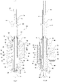
- FIGS. 2 and 3 show an example of a mold filling station 16 with internal gaps 24, 26, 28, which according to the invention are connected by gap seals 30, 32, 34, 20 to the interior 88 of a preform 14 and high-pressure areas 38, 40, 42, and to the environment of the mold filling station 16 by sealing membranes 52 , 54, 56, 58 sealed low pressure areas 44, 46, 48, 50 are divided.
- the mold filling station 16 is shown in a position of use, in which a preform 14 is brought into sealing contact with its mouth area 22 with a contact area of a mold filling nozzle 20 of the mold filling station 16 .
- the mold-filling nozzle 20 is closed, so that no filling material can get into the interior space 88 of the preform 14 .
- the structure of the mold filling station 16 shown is approximately telescopic with an internal stretch rod 18, a first sleeve-shaped body part 60 enclosing the stretch rod 18 in a longitudinal area in the circumferential direction, and a second sleeve-shaped body part 62 enclosing the first sleeve-shaped body part 60 in a longitudinal area in the circumferential direction.
- incl. stretching rod) 18, 60, 62 are each mounted in a housing block 64 of the mold filling station 16 so that they can be displaced axially.
- the body region of the form-filling nozzle 20 that sealingly encompasses the stretch rod 18 on its outer circumference forms a gap seal according to the invention, which extends a gap space 24 formed between the stretch rod 18 and the first sleeve-like body part 60 that encompasses the stretch rod 18 into a high-pressure region 42 located in the mouth region of the form-filling nozzle 20 and a low-pressure area 44 sealed off from the environment of the mold filling station 16 by means of a sealing membrane 52 in the head area of the mold filling station 16 .
- the tubular sealing membrane 52 is fastened with a first opening edge to the stretch rod 18 in a sealing manner and with a second opening edge to the first body part 60 in a sealing manner.
- the low-pressure area 44 is thus sealed off from the area surrounding the mold filling station 16 .
- the outer circumference of the stretch rod 18 slides sealingly on an inner wall of the mold-filling nozzle 20, so that a pressure of up to 35 bar or more than 35 bar is introduced into the preform 14
- Filling material is prevented from penetrating into the low-pressure area 44 above the form-filling nozzle 20 .
- Any leaks that get from the high-pressure area 42 into the low-pressure area 44 despite the sealing by means of the gap seal are prevented from exiting the gap space 24 by the sealing membrane 52 .
- the sealing membrane 52 enables a large stroke of the stretch rod of up to 250 mm or more than 250 mm. As shown, the sealing membrane 52 can be enclosed by the head-side end region of the sleeve-shaped body part 60 in order to support a wrinkle-free turning in and out of the tubular sealing membrane 52 during the axial displacement of the stretch rod 18 .
- the sleeve-like body part 60 which is mounted displaceably relative to the form-filling nozzle 20 and displaceable relative to the stretching rod 18, forms a plunger-like closing body with which the form-filling nozzle 20 can be brought into an open position and into a closed position.
- a lifting flange 82 that protrudes radially from the closing body 60 can be provided in the end region of the closing body 60 that protrudes out of the housing block 64 on the head side, which works together with a lifting device (not shown), embodied, for example, as a cam track.
- the first sleeve-like body part 60 that forms the closing body is surrounded by a further sleeve-like body part 62, with a further gap space 26 being formed between the first body part 60 and the second body part 62, which also extends from a gap seal 34 into a high-pressure region 40 on the preform side and into a head-side low-pressure area 46 is divided.
- the high-pressure area 40 on the preform side can be connected in a communicating manner to the interior 88 of the preform 14 brought into sealing contact with the mold filling nozzle 20 with its mouth area 22 by the movement of the closing body 60 into the open position.
- the head-side low-pressure area 46 is sealed with a bellows-like sealing membrane 54 .
- the tubular sealing membrane 54 is fastened with a first opening edge to the closing body 60 in a sealing manner and with a second opening edge to the second body part 62 in a sealing manner.
- the low-pressure area 46 is thus sealed off from the area surrounding the mold filling station 16 .
- the sealing membrane 54 can be shaped like an accordion as a bellows.
- the second sleeve-shaped body part 62 enclosing the closing body 60 in the circumferential direction is mounted in the present case in an axially displaceable manner in a passage of a housing block 64 .
- the body part 62 is connected to the mold filling nozzle 20 in a movement-coupled manner. With an axial displacement of the body part 62, the mold-filling nozzle 20 can be moved closer to or removed from the mouth area of a preform 14 held, for example, below the mold-filling station 16 in a filling mold (not shown).
- a radially protruding lifting flange 84 can be provided in the head-side end area of the body part 62, which cooperates with a lifting device (not shown) designed, for example, as a cam track.
- a further gap space 28 is formed between the inner wall of the housing block 64 and the outer wall of the second sleeve-shaped body part 62 .
- the housing block 64 is sealed against the sleeve-shaped body part 62 with a sealing membrane 58 . Between the second gap seal 32 and the sealing membrane 58 there is thus formed a further low-pressure region 48 which is sealed off from the surroundings of the mold filling station 16 .
- the sealing membranes 56 and 58 are tubular. During the axial displacement of the second body part 62 in the passage of the housing block 64, the edge of the opening of the sealing membranes 56, 58, which is tightly fastened to the second body part 62, inverts into the inner region of their tubular body.
- a filling material is introduced into the high-pressure area 38 through a filling material channel 80 which is connected in a communicating manner to the outer annular gap-shaped high-pressure area 38 .
- the different gap seals 30, 32 arranged on the housing block 64 delimit the annular gap-shaped high-pressure area 38 and prevent the filling material introduced into the high-pressure area at a pressure of up to 35 bar or more than 35 bar from escaping into the low-pressure areas 48, 50. From the outer The filling material reaches the second body part in a longitudinal section surrounding the high-pressure area 38 in the form of an annular gap through one or more high-pressure fluid channels 74 breaking through the sleeve wall of body part 62 into the inner high-pressure region 40.
- the high-pressure region 40 is connected to the interior 88 of a preform 14 sealingly resting with its mouth region 22 on the mold-filling nozzle 20 , so that the filling can get into the interior 88 of the preform 14.
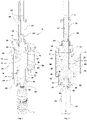
- the Figures 4 and 5 show the mold filling station 16 according to the invention with a container 12 formed and filled from the preform 14.
- the closing body 60 is in an open position that opens the mold filling nozzle 20.
- the stretching rod 18 is pushed into the interior space 88 of the preform 14 in order to guide and stretch the preform 14 .
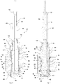
- the Figures 6 and 7 show a mold filling station 16 according to the invention in a cleaning position.
- the form-filling nozzle 20 is closed with a cap 86 so that a flushing fluid introduced into the high-pressure areas cannot escape through the form-filling nozzle opening.
- the stretching rod 18 is moved into a displacement position in which the outer circumference of the stretching rod 18 is no longer in sealing contact with the central passage of the mold-filling nozzle 20 .
- the end region of the stretch rod 18 on the preform side is shifted into a peripherally expanded region of the central passage of the mold filling nozzle 20 .
- the high-pressure areas 38, 40, 42 are connected to the low-pressure areas 44, 46, 48 and 50 via the central passage of the mold-filling nozzle 20.
- the low pressure areas 44,46,48,50 are interconnected by low pressure fluid channels 66,68,70,72.
- a flushing fluid is introduced through the filling material channel 80 or the flushing fluid channels 76, 78, the gap spaces 24, 26, 28 can be completely flushed to remove any filling material residues.
Landscapes
- Engineering & Computer Science (AREA)
- Manufacturing & Machinery (AREA)
- Mechanical Engineering (AREA)
- Blow-Moulding Or Thermoforming Of Plastics Or The Like (AREA)
Claims (11)
- Dispositif de remplissage (10) de moule pour la fabrication, à partir de préformes (14) thermiquement conditionnées, de récipients (12) remplis d'un produit de remplissage liquide, avec au moins une station de remplissage (16) de moule pour le moulage et le remplissage d'une préforme (14), la station de remplissage de moule (16) présentant une barre d'étirage (18) logée de façon à pouvoir coulisser longitudinalement pour guider et étirer la préforme (14), caractérisé en ce que la station de remplissage (16) de moule présente, entre deux parties de corps (18; 60; 62; 64) de la station de remplissage (16) de moule disposées de façon à pouvoir coulisser l'une par rapport à l'autre, au moins un interstice (24; 26; 28), lequel est, en une position d'utilisation de la station de remplissage (16) de moule, subdivisé de façon étanche en une zone à haute pression (38 ; 40 ; 42) et une zone à basse pression (44; 46; 48; 50), subdivision réalisée au moyen d'un joint interstitiel (30; 32; 34; 36) agissant sur une surface de l'une des parties de corps, la zone à haute pression (38; 40; 42) pouvant être mise en communication avec l'espace intérieur (86) de la préforme (14) et la zone à basse pression (44; 46; 48; 50) étant étanchéifiée au moyen d'une membrane d'étanchéification (52; 54; 56; 58) flexible respectivement reliée de manière étanche aux parties de corps mobiles l'une par rapport à l'autre, l'un des interstices (24; 26; 28) étant formé entre la barre d'étirage (18) et une première partie de corps (60) en forme de douille qui entoure en sens périphérique au moins une section longitudinale la barre d'étirage (18)
- Dispositif de remplissage (10) de moule selon la revendication 1, caractérisé en ce que l'un des interstices (24; 26; 28) est formé entre une première partie de corps (60) en forme de douille qui entoure en sens périphérique au moins une section longitudinale la barre d'étirage (18) et une seconde partie de corps (62) en forme de douille qui entoure en sens périphérique au moins une section longitudinale de la première partie de corps (60).
- Dispositif de remplissage (10) de moule selon l'une des revendications précédentes, caractérisé en ce que l'un des interstices (24; 26; 28) est formé entre un boîtier (64) extérieur de la station de remplissage (16) de moule et une partie de corps (62) intérieure dont au moins une section longitudinale est entourée en sens périphérique par le boîtier (64).
- Dispositif de remplissage (10) de moule selon l'une des revendications précédentes, caractérisé en ce que l'un au moins des interstices (24; 26; 28) est un interstice annulaire formé entre deux parties de corps de la station de remplissage (16) de moule pouvant coulisser axialement l'une par rapport à l'autre.
- Dispositif de remplissage (10) de moule selon l'une des revendications précédentes, caractérisé en ce que l'un des interstices (26) présente une zone à haute pression (38) formée entre deux joints interstitiels (30; 32) et deux zones à basse pression (48; 50) respectivement étanchéifiées au moyen d'une membrane d'étanchéification (54; 58).
- Dispositif de remplissage (10) de moule selon l'une des revendications précédentes, caractérisé en ce que la station de remplissage (16) de moule présente au moins deux zones à basse pression (44; 46; 48; 50) formées entre un joint interstitiel (30; 32; 34; 36) et une membrane d'étanchéification (52; 54; 56; 58) et reliées de façon à pouvoir communiquer par un canal (66; 68; 70; 72) pour fluide à basse pression.
- Dispositif de remplissage (10) de moule selon l'une des revendications précédentes, caractérisé en ce que la station de remplissage (16) de moule présente au moins deux zones à haute pression (38; 40) étanchéifiées par rapport à une zone à basse pression (48; 50) par un joint interstitiel (30; 32; 34) et agencées de façon à pouvoir coulisser l'une par rapport à l'autre, ces deux zones à haute pression (38; 40) pouvant coulisser l'une par rapport à l'autre étant reliées de façon à pouvoir communiquer par un canal (74) pour fluide à haute pression.
- Dispositif de remplissage (10) de moule selon l'une des revendications précédentes, caractérisé en ce que toutes les zones à basse pression (44; 46; 48; 50) de la station de remplissage (16) de moule formées entre un joint interstitiel (30; 32; 34; 36) et une membrane d'étanchéification (52; 54; 56; 58) sont reliées de façon à pouvoir communiquer par des canaux (66; 68; 70; 72) pour fluide à basse pression et/ou en ce que toutes les zones à haute pression (38; 40; 42) étanchéifiées par rapport à une zone à basse pression (44; 46; 48; 50) par un joint interstitiel (30; 32; 34; 36) sont reliées de façon à pouvoir communiquer par des canaux (74) pour fluide à haute pression.
- Dispositif de remplissage (10) de moule selon l'une des revendications précédentes, caractérisé en ce que l'une au moins des membranes d'étanchéification (52; 54; 56; 58) est de forme tubulaire, un premier bord d'ouverture de la membranes d'étanchéification tubulaire (52; 54; 56; 58) étant relié de manière étanche par complémentarité de forme, par accouplement à transmission de force et/ou par assemblage de matériau à une première des deux parties de corps (18; 60; 62; 64) agencées de façon à pouvoir coulisser l'une par rapport à l'autre, et un second bord d'ouverture de la membranes d'étanchéification tubulaire (52; 54; 56; 58) étant relié de manière étanche par complémentarité de forme, par accouplement à transmission de force ou par assemblage de matériau à la seconde des deux parties de corps (18; 60; 62; 64) agencées de façon à pouvoir coulisser l'une par rapport à l'autre.
- Dispositif de remplissage (10) de moule selon l'une des revendications précédentes, caractérisé en ce que la station de remplissage (16) de moule peut, pour le rinçage des interstices (24; 26; 28), être placée en une position de rinçage dans laquelle au moins une zone à haute pression (38; 40; 42) est reliée à une zone à basse pression (44; 46; 48; 50) de façon à pouvoir communiquer avec celle-ci, une position de rinçage notamment étant prévue dans laquelle toutes les zones à basse pression (44; 46; 48; 50) sont reliées à toutes les zones à haute pression (38; 40; 42) de façon à pouvoir communiquer avec celles-ci.
- Dispositif de remplissage (10) de moule selon l'une des revendications précédentes, caractérisé en ce qu'un canal d'évacuation (76; 78) relié à une zone collectrice extérieure à la station de remplissage (16) de moule et servant à l'évacuation de liquide de fuite provenant de la zone à haute pression (38; 40; 42) et pénétrant dans la zone à basse pression (44; 46; 48; 50) débouche dans l'une au moins des zones à basse pression (44; 46; 48; 50) d'un interstice (24; 26; 28).
Applications Claiming Priority (2)
| Application Number | Priority Date | Filing Date | Title |
|---|---|---|---|
| DE102017120812.7A DE102017120812A1 (de) | 2017-09-08 | 2017-09-08 | Formfüllstation |
| PCT/EP2018/074045 WO2019048563A1 (fr) | 2017-09-08 | 2018-09-06 | Station de remplissage de moule |
Publications (2)
| Publication Number | Publication Date |
|---|---|
| EP3678835A1 EP3678835A1 (fr) | 2020-07-15 |
| EP3678835B1 true EP3678835B1 (fr) | 2022-04-06 |
Family
ID=63524286
Family Applications (1)
| Application Number | Title | Priority Date | Filing Date |
|---|---|---|---|
| EP18765875.2A Active EP3678835B1 (fr) | 2017-09-08 | 2018-09-06 | Station de moulage et remplisage |
Country Status (3)
| Country | Link |
|---|---|
| EP (1) | EP3678835B1 (fr) |
| DE (1) | DE102017120812A1 (fr) |
| WO (1) | WO2019048563A1 (fr) |
Cited By (1)
| Publication number | Priority date | Publication date | Assignee | Title |
|---|---|---|---|---|
| DE102022129297A1 (de) * | 2022-11-07 | 2024-05-08 | Khs Gmbh | Vorrichtung und Verfahren zum Herstellen eines mit flüssigem Füllgut befüllten Behälters aus einem thermisch konditionierten Vorformling |
Families Citing this family (1)
| Publication number | Priority date | Publication date | Assignee | Title |
|---|---|---|---|---|
| CN116534363B (zh) * | 2023-06-07 | 2026-02-06 | 赣州宏达聚氨酯有限公司 | 一种可防止氧化的油墨密封灌装装置 |
Citations (1)
| Publication number | Priority date | Publication date | Assignee | Title |
|---|---|---|---|---|
| DE102013110088A1 (de) * | 2013-09-13 | 2015-03-19 | Krones Ag | Blasformmaschine mit pneumatisch betätigtem Blasluftventil und Verfahren zum Betreiben einer solchen Blasformmaschine |
Family Cites Families (9)
| Publication number | Priority date | Publication date | Assignee | Title |
|---|---|---|---|---|
| DE2352926A1 (de) | 1973-10-22 | 1975-04-24 | Heidenreich & Harbeck Gmbh | Verfahren und vorrichtung zum erwaermen eines werkstueckes aus kunststoff |
| DE4212583A1 (de) | 1992-04-15 | 1993-10-21 | Krupp Corpoplast Masch | Vorrichtung zur Blasformung |
| DE4340291A1 (de) | 1993-11-26 | 1995-06-01 | Krupp Corpoplast Masch | Mehrfachnutzung von Blasluft |
| US6635216B2 (en) * | 2001-05-18 | 2003-10-21 | Graham Engineering Corporation | Blow molding machine and method |
| US7914726B2 (en) | 2006-04-13 | 2011-03-29 | Amcor Limited | Liquid or hydraulic blow molding |
| DE102010007541A1 (de) | 2009-12-23 | 2011-06-30 | KHS Corpoplast GmbH, 22145 | Verfahren und Vorrichtung zur Herstellung von gefüllten Behältern |
| DE102011106306A1 (de) * | 2011-06-27 | 2012-12-27 | Krones Ag | Vorrichtung und Verfahren zum Umformen von Kunststoffvorformlingen zu Kunststoffbehältnissen mit durch Rollmembran abgedichteter Reckstangenbewegung |
| DE102014016140A1 (de) * | 2014-10-30 | 2016-05-04 | Khs Corpoplast Gmbh | Verfahren zur Entfernung von Luft aus Vorformlingen zur Herstellung von gefüllten Behältern aus Kunststoff |
| DE102014017871A1 (de) * | 2014-12-04 | 2016-06-09 | Khs Corpoplast Gmbh | Reckstange für den Form-und Füllkopf einer Maschine zum Formen und Füllen von Behältern aus Vorformlingen |
-
2017
- 2017-09-08 DE DE102017120812.7A patent/DE102017120812A1/de not_active Withdrawn
-
2018
- 2018-09-06 WO PCT/EP2018/074045 patent/WO2019048563A1/fr not_active Ceased
- 2018-09-06 EP EP18765875.2A patent/EP3678835B1/fr active Active
Patent Citations (1)
| Publication number | Priority date | Publication date | Assignee | Title |
|---|---|---|---|---|
| DE102013110088A1 (de) * | 2013-09-13 | 2015-03-19 | Krones Ag | Blasformmaschine mit pneumatisch betätigtem Blasluftventil und Verfahren zum Betreiben einer solchen Blasformmaschine |
Cited By (1)
| Publication number | Priority date | Publication date | Assignee | Title |
|---|---|---|---|---|
| DE102022129297A1 (de) * | 2022-11-07 | 2024-05-08 | Khs Gmbh | Vorrichtung und Verfahren zum Herstellen eines mit flüssigem Füllgut befüllten Behälters aus einem thermisch konditionierten Vorformling |
Also Published As
| Publication number | Publication date |
|---|---|
| WO2019048563A1 (fr) | 2019-03-14 |
| EP3678835A1 (fr) | 2020-07-15 |
| DE102017120812A1 (de) | 2019-03-14 |
Similar Documents
| Publication | Publication Date | Title |
|---|---|---|
| EP2388127B1 (fr) | Dispositif de déformation d'ébauches en matière synthétique dotées d'un espace stérile | |
| EP2848387B1 (fr) | Machine de moulage par soufflage avec une valve de soufflage pneumatique, et méthode de mise en oeuvre d'une telle machine. | |
| EP2709820B1 (fr) | Procédé et appareil pour la fabrication de recipients remplis à partir de préformes | |
| EP3088161B1 (fr) | Procede et dispositif de chauffage destine au conditionnement thermique d'ebauches et machine de moulage par soufflage comprenant un tel dispositif | |
| EP2535167B1 (fr) | Machine de formage par soufflage avec arbre de pivotement guidé par palier lisse | |
| DE69607636T2 (de) | Vorrichtung zur herstellung von behältern aus kunststoffmaterial | |
| EP3055120B1 (fr) | Procédé et dispositif pour la production d'un récipient rempli de matière de remplissage | |
| EP2522485B1 (fr) | Machine et procédé de formage par soufflage aseptique avec évacuation stérile de l'air, ainsi que moule de soufflage | |
| EP2537663B1 (fr) | Dispositif et procédé de transformation d'ébauches en matière synthétique pour devenir des conteneurs en plastique avec une évacuation d'air guidée par chambre d'équilibre | |
| DE202013008055U1 (de) | Vorrichtung zum Umformen von Kunststoffvorformlingen mit Reinraum | |
| DE102012107961B4 (de) | Vorrichtung, insbesondere Linearofen mit Reinraum und Verfahren zum Behandeln von Kunststoffbehältnissen in einem Linearofen | |
| EP3678835B1 (fr) | Station de moulage et remplisage | |
| EP3416806B1 (fr) | Procédé et dispositif pour fabriquer des contenants remplis d'un produit de remplissage liquide et fermés avec un bouchon de fermeture | |
| EP2495090B1 (fr) | Souffleuse dotée d'une chambre stérile et d'une entrée de fluides dans la chambre stérile | |
| EP2913174B1 (fr) | Machine de formage par soufflage à centrage du fond de moule de soufflage | |
| EP3554987B1 (fr) | Ensemble élément de remplissage et machine de remplissage | |
| DE102018131396A1 (de) | Aseptische Blasformmaschine mit Entlüftungskanal | |
| EP2735428A1 (fr) | Procédé d'étirage-soufflage et machine d'étirage-soufflage | |
| DE102004034286A1 (de) | Verfahren und Vorrichtung zur Blasformung von Behältern | |
| EP3645237B1 (fr) | Procédé, dispositif, roue de travail et poste de formage pour la fabrication de récipients remplis à partir de préformes thermiquement conditionnées | |
| DE10340916A1 (de) | Verfahren und Vorrichtung zur Handhabung von Werkstücken | |
| DE102011013120A1 (de) | Blasformmaschine mit Sterilraum und steriler Blasluftzuführung | |
| EP4442430B1 (fr) | Dispositif et procédé de fabrication de récipients à partir de préformes | |
| EP4299280B1 (fr) | Dispositif et procédé de déformation d'ébauches en plastique en récipients en plastique | |
| WO2024074439A1 (fr) | Dispositif et procédé de fabrication d'un récipient, rempli d'un matériau de remplissage liquide, à partir d'une préforme thermiquement conditionnée |
Legal Events
| Date | Code | Title | Description |
|---|---|---|---|
| STAA | Information on the status of an ep patent application or granted ep patent |
Free format text: STATUS: UNKNOWN |
|
| STAA | Information on the status of an ep patent application or granted ep patent |
Free format text: STATUS: THE INTERNATIONAL PUBLICATION HAS BEEN MADE |
|
| PUAI | Public reference made under article 153(3) epc to a published international application that has entered the european phase |
Free format text: ORIGINAL CODE: 0009012 |
|
| STAA | Information on the status of an ep patent application or granted ep patent |
Free format text: STATUS: REQUEST FOR EXAMINATION WAS MADE |
|
| 17P | Request for examination filed |
Effective date: 20200305 |
|
| AK | Designated contracting states |
Kind code of ref document: A1 Designated state(s): AL AT BE BG CH CY CZ DE DK EE ES FI FR GB GR HR HU IE IS IT LI LT LU LV MC MK MT NL NO PL PT RO RS SE SI SK SM TR |
|
| AX | Request for extension of the european patent |
Extension state: BA ME |
|
| DAV | Request for validation of the european patent (deleted) | ||
| DAX | Request for extension of the european patent (deleted) | ||
| STAA | Information on the status of an ep patent application or granted ep patent |
Free format text: STATUS: EXAMINATION IS IN PROGRESS |
|
| 17Q | First examination report despatched |
Effective date: 20210113 |
|
| GRAP | Despatch of communication of intention to grant a patent |
Free format text: ORIGINAL CODE: EPIDOSNIGR1 |
|
| STAA | Information on the status of an ep patent application or granted ep patent |
Free format text: STATUS: GRANT OF PATENT IS INTENDED |
|
| INTG | Intention to grant announced |
Effective date: 20211125 |
|
| GRAS | Grant fee paid |
Free format text: ORIGINAL CODE: EPIDOSNIGR3 |
|
| GRAA | (expected) grant |
Free format text: ORIGINAL CODE: 0009210 |
|
| STAA | Information on the status of an ep patent application or granted ep patent |
Free format text: STATUS: THE PATENT HAS BEEN GRANTED |
|
| RAP1 | Party data changed (applicant data changed or rights of an application transferred) |
Owner name: KHS GMBH |
|
| AK | Designated contracting states |
Kind code of ref document: B1 Designated state(s): AL AT BE BG CH CY CZ DE DK EE ES FI FR GB GR HR HU IE IS IT LI LT LU LV MC MK MT NL NO PL PT RO RS SE SI SK SM TR |
|
| REG | Reference to a national code |
Ref country code: GB Ref legal event code: FG4D Free format text: NOT ENGLISH |
|
| REG | Reference to a national code |
Ref country code: CH Ref legal event code: EP |
|
| REG | Reference to a national code |
Ref country code: AT Ref legal event code: REF Ref document number: 1480913 Country of ref document: AT Kind code of ref document: T Effective date: 20220415 |
|
| REG | Reference to a national code |
Ref country code: DE Ref legal event code: R096 Ref document number: 502018009355 Country of ref document: DE |
|
| REG | Reference to a national code |
Ref country code: IE Ref legal event code: FG4D Free format text: LANGUAGE OF EP DOCUMENT: GERMAN |
|
| REG | Reference to a national code |
Ref country code: LT Ref legal event code: MG9D |
|
| REG | Reference to a national code |
Ref country code: NL Ref legal event code: MP Effective date: 20220406 |
|
| PG25 | Lapsed in a contracting state [announced via postgrant information from national office to epo] |
Ref country code: NL Free format text: LAPSE BECAUSE OF FAILURE TO SUBMIT A TRANSLATION OF THE DESCRIPTION OR TO PAY THE FEE WITHIN THE PRESCRIBED TIME-LIMIT Effective date: 20220406 |
|
| PG25 | Lapsed in a contracting state [announced via postgrant information from national office to epo] |
Ref country code: SE Free format text: LAPSE BECAUSE OF FAILURE TO SUBMIT A TRANSLATION OF THE DESCRIPTION OR TO PAY THE FEE WITHIN THE PRESCRIBED TIME-LIMIT Effective date: 20220406 Ref country code: PT Free format text: LAPSE BECAUSE OF FAILURE TO SUBMIT A TRANSLATION OF THE DESCRIPTION OR TO PAY THE FEE WITHIN THE PRESCRIBED TIME-LIMIT Effective date: 20220808 Ref country code: NO Free format text: LAPSE BECAUSE OF FAILURE TO SUBMIT A TRANSLATION OF THE DESCRIPTION OR TO PAY THE FEE WITHIN THE PRESCRIBED TIME-LIMIT Effective date: 20220706 Ref country code: LT Free format text: LAPSE BECAUSE OF FAILURE TO SUBMIT A TRANSLATION OF THE DESCRIPTION OR TO PAY THE FEE WITHIN THE PRESCRIBED TIME-LIMIT Effective date: 20220406 Ref country code: HR Free format text: LAPSE BECAUSE OF FAILURE TO SUBMIT A TRANSLATION OF THE DESCRIPTION OR TO PAY THE FEE WITHIN THE PRESCRIBED TIME-LIMIT Effective date: 20220406 Ref country code: GR Free format text: LAPSE BECAUSE OF FAILURE TO SUBMIT A TRANSLATION OF THE DESCRIPTION OR TO PAY THE FEE WITHIN THE PRESCRIBED TIME-LIMIT Effective date: 20220707 Ref country code: FI Free format text: LAPSE BECAUSE OF FAILURE TO SUBMIT A TRANSLATION OF THE DESCRIPTION OR TO PAY THE FEE WITHIN THE PRESCRIBED TIME-LIMIT Effective date: 20220406 Ref country code: ES Free format text: LAPSE BECAUSE OF FAILURE TO SUBMIT A TRANSLATION OF THE DESCRIPTION OR TO PAY THE FEE WITHIN THE PRESCRIBED TIME-LIMIT Effective date: 20220406 Ref country code: BG Free format text: LAPSE BECAUSE OF FAILURE TO SUBMIT A TRANSLATION OF THE DESCRIPTION OR TO PAY THE FEE WITHIN THE PRESCRIBED TIME-LIMIT Effective date: 20220706 |
|
| PG25 | Lapsed in a contracting state [announced via postgrant information from national office to epo] |
Ref country code: RS Free format text: LAPSE BECAUSE OF FAILURE TO SUBMIT A TRANSLATION OF THE DESCRIPTION OR TO PAY THE FEE WITHIN THE PRESCRIBED TIME-LIMIT Effective date: 20220406 Ref country code: PL Free format text: LAPSE BECAUSE OF FAILURE TO SUBMIT A TRANSLATION OF THE DESCRIPTION OR TO PAY THE FEE WITHIN THE PRESCRIBED TIME-LIMIT Effective date: 20220406 Ref country code: LV Free format text: LAPSE BECAUSE OF FAILURE TO SUBMIT A TRANSLATION OF THE DESCRIPTION OR TO PAY THE FEE WITHIN THE PRESCRIBED TIME-LIMIT Effective date: 20220406 Ref country code: IS Free format text: LAPSE BECAUSE OF FAILURE TO SUBMIT A TRANSLATION OF THE DESCRIPTION OR TO PAY THE FEE WITHIN THE PRESCRIBED TIME-LIMIT Effective date: 20220806 |
|
| REG | Reference to a national code |
Ref country code: DE Ref legal event code: R097 Ref document number: 502018009355 Country of ref document: DE |
|
| PG25 | Lapsed in a contracting state [announced via postgrant information from national office to epo] |
Ref country code: SM Free format text: LAPSE BECAUSE OF FAILURE TO SUBMIT A TRANSLATION OF THE DESCRIPTION OR TO PAY THE FEE WITHIN THE PRESCRIBED TIME-LIMIT Effective date: 20220406 Ref country code: SK Free format text: LAPSE BECAUSE OF FAILURE TO SUBMIT A TRANSLATION OF THE DESCRIPTION OR TO PAY THE FEE WITHIN THE PRESCRIBED TIME-LIMIT Effective date: 20220406 Ref country code: RO Free format text: LAPSE BECAUSE OF FAILURE TO SUBMIT A TRANSLATION OF THE DESCRIPTION OR TO PAY THE FEE WITHIN THE PRESCRIBED TIME-LIMIT Effective date: 20220406 Ref country code: EE Free format text: LAPSE BECAUSE OF FAILURE TO SUBMIT A TRANSLATION OF THE DESCRIPTION OR TO PAY THE FEE WITHIN THE PRESCRIBED TIME-LIMIT Effective date: 20220406 Ref country code: DK Free format text: LAPSE BECAUSE OF FAILURE TO SUBMIT A TRANSLATION OF THE DESCRIPTION OR TO PAY THE FEE WITHIN THE PRESCRIBED TIME-LIMIT Effective date: 20220406 Ref country code: CZ Free format text: LAPSE BECAUSE OF FAILURE TO SUBMIT A TRANSLATION OF THE DESCRIPTION OR TO PAY THE FEE WITHIN THE PRESCRIBED TIME-LIMIT Effective date: 20220406 |
|
| PLBE | No opposition filed within time limit |
Free format text: ORIGINAL CODE: 0009261 |
|
| STAA | Information on the status of an ep patent application or granted ep patent |
Free format text: STATUS: NO OPPOSITION FILED WITHIN TIME LIMIT |
|
| 26N | No opposition filed |
Effective date: 20230110 |
|
| PG25 | Lapsed in a contracting state [announced via postgrant information from national office to epo] |
Ref country code: AL Free format text: LAPSE BECAUSE OF FAILURE TO SUBMIT A TRANSLATION OF THE DESCRIPTION OR TO PAY THE FEE WITHIN THE PRESCRIBED TIME-LIMIT Effective date: 20220406 |
|
| PG25 | Lapsed in a contracting state [announced via postgrant information from national office to epo] |
Ref country code: MC Free format text: LAPSE BECAUSE OF FAILURE TO SUBMIT A TRANSLATION OF THE DESCRIPTION OR TO PAY THE FEE WITHIN THE PRESCRIBED TIME-LIMIT Effective date: 20220406 |
|
| REG | Reference to a national code |
Ref country code: CH Ref legal event code: PL |
|
| GBPC | Gb: european patent ceased through non-payment of renewal fee |
Effective date: 20220906 |
|
| REG | Reference to a national code |
Ref country code: BE Ref legal event code: MM Effective date: 20220930 |
|
| PG25 | Lapsed in a contracting state [announced via postgrant information from national office to epo] |
Ref country code: SI Free format text: LAPSE BECAUSE OF FAILURE TO SUBMIT A TRANSLATION OF THE DESCRIPTION OR TO PAY THE FEE WITHIN THE PRESCRIBED TIME-LIMIT Effective date: 20220406 |
|
| PG25 | Lapsed in a contracting state [announced via postgrant information from national office to epo] |
Ref country code: LU Free format text: LAPSE BECAUSE OF NON-PAYMENT OF DUE FEES Effective date: 20220906 |
|
| PG25 | Lapsed in a contracting state [announced via postgrant information from national office to epo] |
Ref country code: LI Free format text: LAPSE BECAUSE OF NON-PAYMENT OF DUE FEES Effective date: 20220930 Ref country code: IE Free format text: LAPSE BECAUSE OF NON-PAYMENT OF DUE FEES Effective date: 20220906 Ref country code: CH Free format text: LAPSE BECAUSE OF NON-PAYMENT OF DUE FEES Effective date: 20220930 |
|
| PG25 | Lapsed in a contracting state [announced via postgrant information from national office to epo] |
Ref country code: BE Free format text: LAPSE BECAUSE OF NON-PAYMENT OF DUE FEES Effective date: 20220930 |
|
| PG25 | Lapsed in a contracting state [announced via postgrant information from national office to epo] |
Ref country code: GB Free format text: LAPSE BECAUSE OF NON-PAYMENT OF DUE FEES Effective date: 20220906 |
|
| PG25 | Lapsed in a contracting state [announced via postgrant information from national office to epo] |
Ref country code: CY Free format text: LAPSE BECAUSE OF FAILURE TO SUBMIT A TRANSLATION OF THE DESCRIPTION OR TO PAY THE FEE WITHIN THE PRESCRIBED TIME-LIMIT Effective date: 20220406 |
|
| PG25 | Lapsed in a contracting state [announced via postgrant information from national office to epo] |
Ref country code: MK Free format text: LAPSE BECAUSE OF FAILURE TO SUBMIT A TRANSLATION OF THE DESCRIPTION OR TO PAY THE FEE WITHIN THE PRESCRIBED TIME-LIMIT Effective date: 20220406 Ref country code: HU Free format text: LAPSE BECAUSE OF FAILURE TO SUBMIT A TRANSLATION OF THE DESCRIPTION OR TO PAY THE FEE WITHIN THE PRESCRIBED TIME-LIMIT; INVALID AB INITIO Effective date: 20180906 |
|
| PG25 | Lapsed in a contracting state [announced via postgrant information from national office to epo] |
Ref country code: MT Free format text: LAPSE BECAUSE OF FAILURE TO SUBMIT A TRANSLATION OF THE DESCRIPTION OR TO PAY THE FEE WITHIN THE PRESCRIBED TIME-LIMIT Effective date: 20220406 |
|
| PG25 | Lapsed in a contracting state [announced via postgrant information from national office to epo] |
Ref country code: BG Free format text: LAPSE BECAUSE OF FAILURE TO SUBMIT A TRANSLATION OF THE DESCRIPTION OR TO PAY THE FEE WITHIN THE PRESCRIBED TIME-LIMIT Effective date: 20220406 |
|
| REG | Reference to a national code |
Ref country code: AT Ref legal event code: MM01 Ref document number: 1480913 Country of ref document: AT Kind code of ref document: T Effective date: 20230906 |
|
| PG25 | Lapsed in a contracting state [announced via postgrant information from national office to epo] |
Ref country code: BG Free format text: LAPSE BECAUSE OF FAILURE TO SUBMIT A TRANSLATION OF THE DESCRIPTION OR TO PAY THE FEE WITHIN THE PRESCRIBED TIME-LIMIT Effective date: 20220406 |
|
| PG25 | Lapsed in a contracting state [announced via postgrant information from national office to epo] |
Ref country code: AT Free format text: LAPSE BECAUSE OF NON-PAYMENT OF DUE FEES Effective date: 20230906 |
|
| PG25 | Lapsed in a contracting state [announced via postgrant information from national office to epo] |
Ref country code: AT Free format text: LAPSE BECAUSE OF NON-PAYMENT OF DUE FEES Effective date: 20230906 |
|
| PGFP | Annual fee paid to national office [announced via postgrant information from national office to epo] |
Ref country code: DE Payment date: 20250919 Year of fee payment: 8 |
|
| PGFP | Annual fee paid to national office [announced via postgrant information from national office to epo] |
Ref country code: IT Payment date: 20250923 Year of fee payment: 8 |
|
| PGFP | Annual fee paid to national office [announced via postgrant information from national office to epo] |
Ref country code: FR Payment date: 20250922 Year of fee payment: 8 |
|
| PG25 | Lapsed in a contracting state [announced via postgrant information from national office to epo] |
Ref country code: TR Free format text: LAPSE BECAUSE OF FAILURE TO SUBMIT A TRANSLATION OF THE DESCRIPTION OR TO PAY THE FEE WITHIN THE PRESCRIBED TIME-LIMIT Effective date: 20220406 |
|
| P01 | Opt-out of the competence of the unified patent court (upc) registered |
Free format text: CASE NUMBER: UPC_APP_0014569_3678835/2025 Effective date: 20251125 |
|
| PGFP | Annual fee paid to national office [announced via postgrant information from national office to epo] |
Ref country code: AT Payment date: 20260410 Year of fee payment: 5 |