EP2535439A1 - Dispositif de contrôle de position pour substrat souple - Google Patents
Dispositif de contrôle de position pour substrat souple Download PDFInfo
- Publication number
- EP2535439A1 EP2535439A1 EP10845817A EP10845817A EP2535439A1 EP 2535439 A1 EP2535439 A1 EP 2535439A1 EP 10845817 A EP10845817 A EP 10845817A EP 10845817 A EP10845817 A EP 10845817A EP 2535439 A1 EP2535439 A1 EP 2535439A1
- Authority
- EP
- European Patent Office
- Prior art keywords
- substrate
- flexible substrate
- sandwiching
- pair
- conveying
- Prior art date
- Legal status (The legal status is an assumption and is not a legal conclusion. Google has not performed a legal analysis and makes no representation as to the accuracy of the status listed.)
- Withdrawn
Links
- 0 C[C@]1**=CC1 Chemical compound C[C@]1**=CC1 0.000 description 1
Images





Classifications
-
- C—CHEMISTRY; METALLURGY
- C23—COATING METALLIC MATERIAL; COATING MATERIAL WITH METALLIC MATERIAL; CHEMICAL SURFACE TREATMENT; DIFFUSION TREATMENT OF METALLIC MATERIAL; COATING BY VACUUM EVAPORATION, BY SPUTTERING, BY ION IMPLANTATION OR BY CHEMICAL VAPOUR DEPOSITION, IN GENERAL; INHIBITING CORROSION OF METALLIC MATERIAL OR INCRUSTATION IN GENERAL
- C23C—COATING METALLIC MATERIAL; COATING MATERIAL WITH METALLIC MATERIAL; SURFACE TREATMENT OF METALLIC MATERIAL BY DIFFUSION INTO THE SURFACE, BY CHEMICAL CONVERSION OR SUBSTITUTION; COATING BY VACUUM EVAPORATION, BY SPUTTERING, BY ION IMPLANTATION OR BY CHEMICAL VAPOUR DEPOSITION, IN GENERAL
- C23C14/00—Coating by vacuum evaporation, by sputtering or by ion implantation of the coating forming material
- C23C14/22—Coating by vacuum evaporation, by sputtering or by ion implantation of the coating forming material characterised by the process of coating
- C23C14/56—Apparatus specially adapted for continuous coating; Arrangements for maintaining the vacuum, e.g. vacuum locks
- C23C14/562—Apparatus specially adapted for continuous coating; Arrangements for maintaining the vacuum, e.g. vacuum locks for coating elongated substrates
-
- B—PERFORMING OPERATIONS; TRANSPORTING
- B29—WORKING OF PLASTICS; WORKING OF SUBSTANCES IN A PLASTIC STATE IN GENERAL
- B29C—SHAPING OR JOINING OF PLASTICS; SHAPING OF MATERIAL IN A PLASTIC STATE, NOT OTHERWISE PROVIDED FOR; AFTER-TREATMENT OF THE SHAPED PRODUCTS, e.g. REPAIRING
- B29C66/00—General aspects of processes or apparatus for joining preformed parts
- B29C66/90—Measuring or controlling the joining process
- B29C66/95—Measuring or controlling the joining process by measuring or controlling specific variables not covered by groups B29C66/91 - B29C66/94
-
- B—PERFORMING OPERATIONS; TRANSPORTING
- B29—WORKING OF PLASTICS; WORKING OF SUBSTANCES IN A PLASTIC STATE IN GENERAL
- B29C—SHAPING OR JOINING OF PLASTICS; SHAPING OF MATERIAL IN A PLASTIC STATE, NOT OTHERWISE PROVIDED FOR; AFTER-TREATMENT OF THE SHAPED PRODUCTS, e.g. REPAIRING
- B29C66/00—General aspects of processes or apparatus for joining preformed parts
- B29C66/90—Measuring or controlling the joining process
-
- C—CHEMISTRY; METALLURGY
- C23—COATING METALLIC MATERIAL; COATING MATERIAL WITH METALLIC MATERIAL; CHEMICAL SURFACE TREATMENT; DIFFUSION TREATMENT OF METALLIC MATERIAL; COATING BY VACUUM EVAPORATION, BY SPUTTERING, BY ION IMPLANTATION OR BY CHEMICAL VAPOUR DEPOSITION, IN GENERAL; INHIBITING CORROSION OF METALLIC MATERIAL OR INCRUSTATION IN GENERAL
- C23C—COATING METALLIC MATERIAL; COATING MATERIAL WITH METALLIC MATERIAL; SURFACE TREATMENT OF METALLIC MATERIAL BY DIFFUSION INTO THE SURFACE, BY CHEMICAL CONVERSION OR SUBSTITUTION; COATING BY VACUUM EVAPORATION, BY SPUTTERING, BY ION IMPLANTATION OR BY CHEMICAL VAPOUR DEPOSITION, IN GENERAL
- C23C16/00—Chemical coating by decomposition of gaseous compounds, without leaving reaction products of surface material in the coating, i.e. chemical vapour deposition [CVD] processes
- C23C16/44—Chemical coating by decomposition of gaseous compounds, without leaving reaction products of surface material in the coating, i.e. chemical vapour deposition [CVD] processes characterised by the method of coating
- C23C16/54—Apparatus specially adapted for continuous coating
- C23C16/545—Apparatus specially adapted for continuous coating for coating elongated substrates
-
- H—ELECTRICITY
- H10—SEMICONDUCTOR DEVICES; ELECTRIC SOLID-STATE DEVICES NOT OTHERWISE PROVIDED FOR
- H10F—INORGANIC SEMICONDUCTOR DEVICES SENSITIVE TO INFRARED RADIATION, LIGHT, ELECTROMAGNETIC RADIATION OF SHORTER WAVELENGTH OR CORPUSCULAR RADIATION
- H10F71/00—Manufacture or treatment of devices covered by this subclass
- H10F71/10—Manufacture or treatment of devices covered by this subclass the devices comprising amorphous semiconductor material
- H10F71/107—Continuous treatment of the devices, e.g. roll-to roll processes or multi-chamber deposition
-
- H—ELECTRICITY
- H10—SEMICONDUCTOR DEVICES; ELECTRIC SOLID-STATE DEVICES NOT OTHERWISE PROVIDED FOR
- H10P—GENERIC PROCESSES OR APPARATUS FOR THE MANUFACTURE OR TREATMENT OF DEVICES COVERED BY CLASS H10
- H10P72/00—Handling or holding of wafers, substrates or devices during manufacture or treatment thereof
- H10P72/06—Apparatus for monitoring, sorting, marking, testing or measuring
- H10P72/0606—Position monitoring, e.g. misposition detection or presence detection
-
- H—ELECTRICITY
- H10—SEMICONDUCTOR DEVICES; ELECTRIC SOLID-STATE DEVICES NOT OTHERWISE PROVIDED FOR
- H10P—GENERIC PROCESSES OR APPARATUS FOR THE MANUFACTURE OR TREATMENT OF DEVICES COVERED BY CLASS H10
- H10P72/00—Handling or holding of wafers, substrates or devices during manufacture or treatment thereof
- H10P72/30—Handling or holding of wafers, substrates or devices during manufacture or treatment thereof for conveying, e.g. between different workstations
- H10P72/32—Handling or holding of wafers, substrates or devices during manufacture or treatment thereof for conveying, e.g. between different workstations between different workstations
- H10P72/3202—Mechanical details, e.g. rollers or belts
-
- H—ELECTRICITY
- H10—SEMICONDUCTOR DEVICES; ELECTRIC SOLID-STATE DEVICES NOT OTHERWISE PROVIDED FOR
- H10P—GENERIC PROCESSES OR APPARATUS FOR THE MANUFACTURE OR TREATMENT OF DEVICES COVERED BY CLASS H10
- H10P72/00—Handling or holding of wafers, substrates or devices during manufacture or treatment thereof
- H10P72/30—Handling or holding of wafers, substrates or devices during manufacture or treatment thereof for conveying, e.g. between different workstations
- H10P72/32—Handling or holding of wafers, substrates or devices during manufacture or treatment thereof for conveying, e.g. between different workstations between different workstations
- H10P72/3212—Handling or holding of wafers, substrates or devices during manufacture or treatment thereof for conveying, e.g. between different workstations between different workstations the substrates to be conveyed not being semiconductor wafers or large planar substrates, e.g. chips or lead frames
-
- H—ELECTRICITY
- H10—SEMICONDUCTOR DEVICES; ELECTRIC SOLID-STATE DEVICES NOT OTHERWISE PROVIDED FOR
- H10P—GENERIC PROCESSES OR APPARATUS FOR THE MANUFACTURE OR TREATMENT OF DEVICES COVERED BY CLASS H10
- H10P72/00—Handling or holding of wafers, substrates or devices during manufacture or treatment thereof
- H10P72/30—Handling or holding of wafers, substrates or devices during manufacture or treatment thereof for conveying, e.g. between different workstations
- H10P72/33—Handling or holding of wafers, substrates or devices during manufacture or treatment thereof for conveying, e.g. between different workstations into and out of processing chamber
- H10P72/3314—Continuous loading and unloading into and out of a processing chamber, e.g. transporting belts within processing chambers
-
- Y—GENERAL TAGGING OF NEW TECHNOLOGICAL DEVELOPMENTS; GENERAL TAGGING OF CROSS-SECTIONAL TECHNOLOGIES SPANNING OVER SEVERAL SECTIONS OF THE IPC; TECHNICAL SUBJECTS COVERED BY FORMER USPC CROSS-REFERENCE ART COLLECTIONS [XRACs] AND DIGESTS
- Y02—TECHNOLOGIES OR APPLICATIONS FOR MITIGATION OR ADAPTATION AGAINST CLIMATE CHANGE
- Y02E—REDUCTION OF GREENHOUSE GAS [GHG] EMISSIONS, RELATED TO ENERGY GENERATION, TRANSMISSION OR DISTRIBUTION
- Y02E10/00—Energy generation through renewable energy sources
- Y02E10/50—Photovoltaic [PV] energy
-
- Y—GENERAL TAGGING OF NEW TECHNOLOGICAL DEVELOPMENTS; GENERAL TAGGING OF CROSS-SECTIONAL TECHNOLOGIES SPANNING OVER SEVERAL SECTIONS OF THE IPC; TECHNICAL SUBJECTS COVERED BY FORMER USPC CROSS-REFERENCE ART COLLECTIONS [XRACs] AND DIGESTS
- Y02—TECHNOLOGIES OR APPLICATIONS FOR MITIGATION OR ADAPTATION AGAINST CLIMATE CHANGE
- Y02P—CLIMATE CHANGE MITIGATION TECHNOLOGIES IN THE PRODUCTION OR PROCESSING OF GOODS
- Y02P70/00—Climate change mitigation technologies in the production process for final industrial or consumer products
- Y02P70/50—Manufacturing or production processes characterised by the final manufactured product
-
- Y—GENERAL TAGGING OF NEW TECHNOLOGICAL DEVELOPMENTS; GENERAL TAGGING OF CROSS-SECTIONAL TECHNOLOGIES SPANNING OVER SEVERAL SECTIONS OF THE IPC; TECHNICAL SUBJECTS COVERED BY FORMER USPC CROSS-REFERENCE ART COLLECTIONS [XRACs] AND DIGESTS
- Y10—TECHNICAL SUBJECTS COVERED BY FORMER USPC
- Y10T—TECHNICAL SUBJECTS COVERED BY FORMER US CLASSIFICATION
- Y10T156/00—Adhesive bonding and miscellaneous chemical manufacture
- Y10T156/17—Surface bonding means and/or assemblymeans with work feeding or handling means
-
- Y—GENERAL TAGGING OF NEW TECHNOLOGICAL DEVELOPMENTS; GENERAL TAGGING OF CROSS-SECTIONAL TECHNOLOGIES SPANNING OVER SEVERAL SECTIONS OF THE IPC; TECHNICAL SUBJECTS COVERED BY FORMER USPC CROSS-REFERENCE ART COLLECTIONS [XRACs] AND DIGESTS
- Y10—TECHNICAL SUBJECTS COVERED BY FORMER USPC
- Y10T—TECHNICAL SUBJECTS COVERED BY FORMER US CLASSIFICATION
- Y10T156/00—Adhesive bonding and miscellaneous chemical manufacture
- Y10T156/17—Surface bonding means and/or assemblymeans with work feeding or handling means
- Y10T156/1702—For plural parts or plural areas of single part
- Y10T156/1712—Indefinite or running length work
- Y10T156/1741—Progressive continuous bonding press [e.g., roll couples]
Definitions
- the present invention relates to a lateral position controller for a flexible substrate that is provided in an apparatus conveying a band-shaped flexible substrate and for performing a process such as film forming on the substrate in the conveying path thereof.
- Patent Literature 1 discloses a thin film laminated body manufacturing apparatus that conveys intermittently at a predetermined pitch a band-shaped flexible substrate (polyimide film) supplied from an unwinding roll, laminates a plurality of different thin films having different properties on the flexible substrate using a plurality of film forming units arranged in the conveying direction of the flexible substrate, and winds the substrate on a product roll.
- a band-shaped flexible substrate polyimide film
- the thin film laminated body manufacturing apparatus there are known a type in which a film is formed on a band-shaped flexible substrate conveyed while taking a lateral attitude, that is, an attitude setting the lateral direction of the flexible substrate as the horizontal direction and a type in which a film is formed on a band-shaped flexible substrate conveyed while taking a longitudinal attitude, that is, an attitude setting the lateral direction of the flexible substrate as the vertical direction.
- the latter type has benefits in that the installation area is small and the surface of the substrate is not easily contaminated compared to the former type.
- the conveying span is lengthened, it is difficult to maintain the conveying height to be constant against the gravity, and there is a noticeable tendency that wrinkles occur on the surface of the flexible substrate or the flexible substrate is drooped.
- the inventors have contrived a device adjusting a conveying height of a flexible substrate 1 in a manner such that a pair of upper sandwiching rollers 30 and a pair of lower sandwiching rollers 30' are disposed between film forming units 20 and 20 constituting a thin film laminated body manufacturing apparatus so as to respectively sandwich the upper and lower edges of the flexible substrate 1, and an upward lifting force and a downward pulling force are applied to the upper and lower edges of the flexible substrate 1 so that the rotation directions of the sandwiching portions of respective sandwiching rollers have the inclination angles + ⁇ and - ⁇ directed obliquely upward and downward with respect to the conveying direction F of the flexible substrate 1 (refer to Patent Literatures 1 to 3).
- the device may be advantageously used to stretch the flexible substrate and control the conveying height of the flexible substrate, but may not be promptly applied to a reciprocating film forming process including reverse conveying of the flexible substrate.
- the lifting force and the downward pulling force along the inclination angles are exerted in the opposite vertical direction, so that a problem arises in that the flexible substrate is separated from the sandwiching rollers 30 and 30'.
- the invention is made in view of the above-described problems, and it is an object of the invention to provide a position controller for flexible substrate capable of suppressing drooping or wrinkles of a band-shaped flexible substrate, performing a high-quality process, and handling reverse conveying of the flexible substrate.
- a position controller for flexible substrate provided in a processing apparatus conveying a band-shaped flexible substrate in a longitudinal attitude in the lateral direction and processing the substrate in a processing unit installed on a conveying path of the substrate, the position controller flexible substrate including: a pair of sandwiching rollers that sandwiches an upper edge of the substrate; a supporting mechanism that supports the pair of sandwiching rollers so as to be rotatable and movable close to or away from each other; a pressing means that applies a pressing force to the pair of sandwiching rollers through the supporting mechanism; and a pressing force adjusting means that adjusts the pressing force using the pressing means, wherein each roller constituting the pair of sandwiching rollers is a conical roller having a circumferential surface inclined with respect to the axial direction, and is supported to the supporting mechanism so that a small diameter side of each conical roller is located at a center side of the substrate in the lateral direction and the rotation direction of a sandwiching surface of the substrate
- the flexible substrate is conveyed by a conveying unit such as a feeding roll disposed at each of the upstream and the downstream of the processing unit (the film forming unit) while taking a longitudinal attitude, that is, setting the lateral direction as the vertical direction, and a process such as film forming is performed thereon at the processing unit installed on the conveying path.
- a conveying unit such as a feeding roll disposed at each of the upstream and the downstream of the processing unit (the film forming unit) while taking a longitudinal attitude, that is, setting the lateral direction as the vertical direction, and a process such as film forming is performed thereon at the processing unit installed on the conveying path.
- the tensile force is transmitted to the flexible substrate through a frictional force on the circumferential surface of the roller, the tensile force is proportional to the pressing force of the pair of sandwiching rollers.
- the pressing force is sufficiently large, the tensile force according to the inclination angle of the circumferential surface of the roller is directly applied to the flexible substrate.
- a sliding action more frequently occurs in the sandwiching surface as the pressing force decreases, so that the tensile force decreases. Therefore, when the pressing force using the pressing means is adjusted, the tensile force applied to the flexible substrate may be adjusted, whereby the vertical lateral position of the flexible substrate may be adjusted and the conveying height may be maintained to be constant. Further, since the upper edge of the flexible substrate is stretched toward the edge, it is possible to suppress the drooping or wrinkles of the substrate at the intermediate portion of the conveying span and perform a high-quality process on the flexible substrate.
- the position of the substrate may be controlled to be located at the completely same position using the same device even when the substrate is conveyed in the reverse direction, and the reciprocating process including reverse conveying of the flexible substrate may be handled at low cost.
- each roller constituting the pair of sandwiching rollers is a truncated conical roller.
- the conical roller has a difference in circumference between the large diameter side and the small diameter side. Accordingly, the tensile force is generated for the flexible substrate, and a conveying load is generated due to a difference in speed in the contact range. Since each roller constituting the sandwiching roller is configured as a truncated conical roller, the width of the contact portion is shortened, and the conveying load may be advantageously reduced.
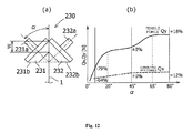
- the inclination angle of the circumferential surface of each conical roller with respect to a rotation shaft may be set to be from 20° to 80°.
- the inclination angle is less than 20°, the tensile force abruptly decreases.
- the inclination angle is larger than 80°, it is difficult to configure the device.
- the inclination angle of the circumferential surface of each conical roller with respect to a rotation shaft is set to be from 45° to 65°.
- the conveying resistance also increases with an increase in the inclination angle, but when the inclination angle is 45° or more, the conveying resistance very slightly increases. Further, when the inclination angle becomes more than 65°, the tensile force hardly increases.
- the invention is also applied to an embodiment in which a pair of sandwiching rollers is disposed at each of upper and lower sides of the flexible substrate. That is, in the preferred embodiment of the invention, there are further provided a pair of lower sandwiching rollers that sandwiches a lower edge of the substrate; and a supporting mechanism and a pressing means that are configured in the same manner as the supporting mechanism and the pressing means and support the pair of lower sandwiching rollers.
- the flexible substrate is moved upward or downward due to a difference in stretching component of the pressing force acting on the upper and lower sandwiching surfaces through the adjustment of the pressing force while stretching the flexible substrate in both upper and lower lateral directions, so that the conveying height may be controlled. Accordingly, the wrinkles of the flexible substrate may be effectively suppressed and the positional precision of the flexible substrate may further improve.
- the processing apparatus is a thin film laminated body manufacturing apparatus that includes a plurality of film forming units serving as the processing unit and disposed in parallel at the same pitch in the conveying path of the substrate and sequentially laminates thin films on the surface of the substrate while intermittently conveying the substrate at the pitch corresponding to the film forming unit.
- the pair of upper sandwiching roller and the pair of lower sandwiching rollers are disposed between the plurality of film forming units.
- the processing apparatus is a thin film laminated body manufacturing apparatus that continuously conveys the substrate and laminates thin films on the surface of the substrate in a film forming unit as the processing unit.
- the plurality of pairs of upper sandwiching roller and the plurality of pairs of lower sandwiching rollers are disposed at the upper and lower sides of the film forming unit in the conveying direction.
- a plurality of support rollers may be further provided in series in the conveying direction so as to support the substrate while being located at a position between a thin film forming region of the substrate and the plurality of pairs of upper sandwiching rollers and a position between the thin film forming region and the plurality of pairs of lower sandwiching rollers.
- the flexible substrate may be reliably supported around the film forming unit by the heat-resistant support roller not including the movable portion for adjusting the pressing force, the group of the pair of sandwiching rollers may be disposed in the film forming unit to be away from each other, the influence of the radiation heat with respect to the sandwiching roller may be reduced, and a degree in freedom of selecting the material of the sandwiching roller advantageously improves.
- the invention may also be applied to a position controller for flexible substrate in a processing apparatus that conveys a band-shaped flexible substrate in a horizontal attitude other than the longitudinal attitude in the lateral direction, the vertical direction, or the inclined direction and performs a process such as film forming thereon.
- the invention may be applied to a position controller for flexible substrate provided in a processing apparatus conveying a band-shaped flexible substrate and processing the substrate in a processing unit installed on a conveying path of the substrate, the position controller for flexible substrate including: each pair of sandwiching rollers that sandwiches each edge of the substrate; each supporting mechanism that supports each pair of sandwiching rollers so as to be rotatable and movable close to or away from each other in each pair; a pressing means that applies a pressing force to each pair of sandwiching rollers through each supporting mechanism; and a pressing force adjusting means that adjusts the pressing force using the pressing means, wherein each roller constituting each pair of sandwiching rollers is a conical roller having a circumferential surface inclined with respect to the axial direction, and is supported to each supporting mechanism so that a small diameter side of each conical roller is located at a center side of the substrate in the lateral direction and the rotation direction of a sandwiching surface of the substrate is the same as the conveying direction of the substrate.
- the sandwiching rollers configured as a pair of conical rollers sandwiching each edge of the flexible substrate are rotated by the conveying force of the flexible substrate, the sandwiching rollers are led to the center of the flexible substrate in the lateral direction according to a difference in circumference between the large diameter side and the small diameter side, and as a result of the relative movement, a tensile force is applied to the flexible substrate toward the lateral edge. Since the tensile force changes in accordance with the pressing force using each pressing means, when the pressing force using each pressing means is adjusted, it is possible to adjust the lateral position of the flexible substrate and suppress meandering of the flexible substrate while stretching the substrate in the lateral direction. Furthermore, since such an action is not dependent on the rotation direction of each sandwiching roller and the rotation direction of each sandwiching surface is the same as the conveying direction of the substrate, the same position control may be performed even in the reverse conveying.
- each roller constituting the pair of sandwiching rollers may be formed as a truncated conical roller.
- the position controller for flexible substrate according to the invention may effectively suppress drooping or wrinkles of the flexible substrate when performing a process such as film forming on the conveying band-shaped flexible substrate, maintaining the lateral position to be constant to perform a high-quality process thereon, and handling a reciprocating process including reverse conveying of the flexible substrate at low cost.
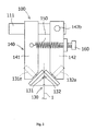
- FIG. 2 is a front view illustrating a position controller for substrate 100 according to a first embodiment of the invention when seen from the upstream in the conveying direction.
- the thin film laminated body manufacturing apparatus conveys a band-shaped flexible substrate 1 (flexible film) in the horizontal direction inside a vacuum chamber 10 maintained at a predetermined vacuum degree while taking a longitudinal attitude, that is, the lateral direction is set as the vertical direction, and laminates thin films on the surface of the flexible substrate 1 using a plurality of film forming units 20 (film forming units) arranged in parallel along the conveying path of the flexible substrate 1.
- Feeding roll or tension roll constituting a conveying unit of the flexible substrate 1 are disposed at the upstream and the downstream in the conveying direction of the film forming unit, and an unwinding roll and a winding roll of the flexible substrate 1 are further disposed at the upstream and the downstream in the conveying direction.
- guide roll (idle roll) are disposed between the feeding roll and the film forming unit of the upstream and the downstream so as to guide the flexible substrate 1 while being folded back at the upstream and the downstream of the film forming unit and set the linear conveying path of the flexible substrate 1 in the film forming unit. Since this configuration is the same as that of the related art, the configuration is not described in detail, but is schematically shown in FIG. 10C.
- the position controller for substrate 100 is disposed at the upper portion of the conveying path in the film forming unit so as to control the vertical position of the flexible substrate 1 conveyed through the film forming unit while being suspended between the guide rolls so that the conveying height is maintained to be constant and the flexible substrate 1 is stretched in the lateral direction, that is, the vertical direction, and includes: a pair of sandwiching rollers 130 that sandwiches the upper edge of the flexible substrate 1; a supporting mechanism 140 that supports rollers 131 and 132 constituting the pair of sandwiching rollers 130 to be rotatable and movable close to or away from each other; a pressing means (150) that applies a pressing force to the pair of sandwiching rollers 130 (131 and 132) through the supporting mechanism 140; a pressing force adjusting means (160); and the like as shown in FIG. 2 .
- the rollers 131 and 132 constituting the pair of sandwiching rollers 130 are all formed as conical rollers formed in the same shape to have circumferential surfaces 131b and 132b inclined with respect to the axial direction.
- One of them is a fixed roller 131
- the other is a movable roller 132
- the fixed roller 131 is rotatably supported by a shaft 131a
- the movable roller 132 is rotatably supported by a shaft 132a.
- each front end side (small diameter side) is located at the downside of the drawing corresponding to the center in the vertical width direction of the flexible substrate 1, and each large diameter portion is located at the upside of the drawing corresponding to the edge side of the flexible substrate 1.
- the shafts 131a and 132a form an inclination angle corresponding to the inclination (that is, the vertex angle of the conical shape) of each of the circumferential surfaces 131b and 132b with respect to the conveying surface (flexible substrate 1) within the imaginary plane D perpendicular to the conveying direction of flexible substrate 1, and are obliquely held by the front ends of a fixed support member 141 and a movable support member 142. Accordingly, the rotation direction in the sandwiching surfaces of the sandwiching rollers 131 and 132 is set to be the same direction as the conveying direction of the flexible substrate 1.
- the upper end of the fixed support member 141 is fixed to a bracket 111, and the bracket 111 is fixed to a structure component of a vacuum chamber (not shown).
- the fixed support member 141 and the bracket 111 may be integrally formed with each other.
- a hinge 142b of the upper end of the movable support member 142 is swingably connected to the bracket 111, and when the movable support member 142 swings about the hinge 142b, the movable roller 132 is movable to be close to or away from the fixed roller 131.
- a spring 150 (tension spring) as a pressing means is interposed between the fixed support member 141 and the movable support member 142.
- One end of the spring 150 is connected to the fixed support member 141, and the other end of the spring 150 is connected to the movable support member 142 through a pressing force adjusting screw 160.
- the pressing force adjusting screw 160 rotates to adjust the initial displacement of the spring 150, the pressing force (contact pressure) of the movable roller 132 with respect to the fixed roller 131 may be adjusted.
- Each of the sandwiching rollers 131 and 132 constituting the pair of sandwiching rollers 130 is formed of, for example, metal, ceramic, plastic, or the like, or is formed by attaching an elastic body such as rubber to a circumference of a core body formed of such a material.
- the rollers 131 and 132 are rotatably supported through bearings capable of receiving a thrust load so as to be held at predetermined axial positions with respect to the shafts 131a and 132a (support shafts).
- the shafts 131a and 132a (rotary shafts) may be rotatably supported to the front ends of the fixed support member 141 and the movable support member 142 through a bearing capable of receiving a thrust load.
- the tensile force Qy generated by each of the sandwiching rollers 131 and 132 is transmitted as a frictional force to the flexible substrate 1, the tensile force is basically proportional to the pressing force Px generated by each of the sandwiching rollers 131 and 132. Since the pressing force Px generated by each of the sandwiching rollers 131 and 132 is proportional to the elastical displacement of the spring 150, when the initial displacement of the spring 150 is adjusted by rotating the pressing force adjusting screw 160, the tensile force Qy with respect to the upper edge of the flexible substrate 1 may be adjusted. Since the tensile force Qy serves as a lifting force that lifts the upper edge of the flexible substrate 1 against the gravity, the position of the upper edge of the flexible substrate 1 may be adjusted.
- the apparatus is operated by setting the pressing force to the optimal value obtained from a test operation by the use of the manual pressing force adjusting screw 160 as the pressing force adjusting means.
- the conveying height of the flexible substrate 1 may be controlled through a feed-back control using an actuator rotating the pressing force adjusting screw 160 or directly or indirectly displacing the support point of the spring 150 through a mechanism, a sensor detecting the position of the upper edge of the flexible substrate 1, and a control device controlling the actuator on the basis of the detection value of the sensor.
- FIG. 7 is a characteristic diagram illustration a relation between the pressing force Px and the tensile force Qy of the conical sandwiching roller (130) according to the embodiment of the invention and the cylindrical sandwiching roller (30) shown in FIG. 1 as a comparative example.
- the tensile force Qy of the cylindrical sandwiching roller (30) depicted by the dashed line of the drawing increases in proportional to the pressing force Px within a range with a comparatively small pressing force Px.
- the pressing force Px further increases, the tensile force tends to be gradually saturated, but the tensile force Qy of the conical sandwiching roller (130) depicted by the solid line of the drawing tends to increase in proportional to the pressing force Px in the wide range.
- FIG. 6A visually illustrates the enlarged contact surface (sandwiching surface) in the circumferential direction in the case where the standard pressing force is exerted
- FIG. 6B corresponds to the case where the pressing force increases
- FIG. 6C corresponds to the case where the pressing force decreases. Since the sandwiching roller 131 (132) is formed in a conical shape, the contact surface 131c with respect to the flexible substrate 1 is formed in a fan shape or a wedge shape, and as the pressing force Px increases, the substantial sandwiching point (to be described later) formed by the sandwiching rollers 131 and 132 is shifted to the large diameter side.
- the tensile force Qy is transmitted to the flexible substrate 1 in accordance with the shape of each of the sandwiching rollers 131 and 132.
- the pressing force Px is small, the sliding action within the contact surface gradually more occurs, so that the transmitted tensile force Qy decreases. Due to the unique characteristics of the mechanism generating the tensile force Qy, the tensile force Qy may be increased in proportional to the pressing force Px in the wide range, and even in the region where the pressing force Px is large, the tensile force Qy is not easily saturated.
- FIGS. 4A, 4B , and 5 illustrate embodiments in which the position controller for substrate 100 of the first embodiment is applied to a stepwise thin film forming apparatus 110 shown in FIG. 1 .
- Only one film forming unit 20 is shown in FIG. 4 , but as assumed above, the plurality of film forming units 20 are disposed in parallel inside the common vacuum chamber 10 in the conveying direction.
- Each film forming unit 20 is formed as a vacuum depositing unit that performs chemical vapor deposition (CVD) such as plasma CVD or physical vapor deposition (PVD) such as sputtering.
- CVD chemical vapor deposition
- PVD physical vapor deposition
- Each film forming unit 20 includes an electrode 21 (a high frequency electrode or a target having a plurality of raw gas discharging holes formed on the surface) and a ground electrode 22 having a heater embedded therein disposed to face each other with the flexible substrate 1 interposed therebetween, and each of the electrode 21 and the ground electrode 22 is received in a chamber opened toward the conveying surface of the flexible substrate 1.
- the pair of sandwiching rollers 130 may not be installed between the electrode 21 and the ground electrode 22.
- the position controller for substrate 100 is installed at a position before or behind the film forming unit 20, that is, a position between the film forming units 20.
- a pair of sandwiching rollers 130 and 130' is respectively disposed at the upper and lower sides of the conveying path.
- the pair of lower sandwiching rollers 130' may have the same structure as that of the pair of upper sandwiching rollers 130 so that the structure is reversed in the vertical direction.
- the downward tensile force - Qy is exerted downward with respect to the lower edge of the flexible substrate 1 from the pair of lower sandwiching rollers 1 in parallel 30' together with the tensile force Qy exerted upward with respect to the upper edge of the flexible substrate 1 from the pair of upper sandwiching rollers 130, so that the flexible substrate 1 is stretched to both sides in the vertical direction and such a difference serves as a lifting force against the gravity of the flexible substrate 1. Therefore, in the pair of upper and lower sandwiching rollers 130 and 130', the tensile force of the pair of upper sandwiching rollers 130 is set to be larger than that of the pair of lower sandwiching rollers 130' when the influence of the gravity is large due to the long conveying span or the like.
- the substantial sandwiching point (the point where the conveying force of the flexible substrate 1 is transmitted as a stop frictional force to the sandwiching roller) where the circumferential speed is equal to the conveying speed of the flexible substrate 1 becomes the large diameter side point where the transmitting torque is large, and a sliding action is generated in the opposite direction to the conveying direction F of the flexible substrate 1 at the small diameter side in relation to the point due to a difference in circumferential speed.
- FIG. 3C corresponding to the enlarged view of FIG. 3(b) , the small diameter side of the conical sandwiching roller 131 rotates from S0 to S2 while the substantial sandwiching point moves from L1 to L2.
- the small diameter side of the sandwiching roller 131 is located at S1 when the sandwiching point is located at L1, and the flexible substrate 1 generates a sliding action in the opposite direction to the conveying direction F as much as a difference between S1 and S0, so that the sliding action is transmitted to the flexible substrate 1 as a frictional force and becomes a conveying resistance Qx.
- FIG. 10A illustrates a change of the conveying resistance Qx in accordance with the conveying tensile force of the position controller for substrate 100 according to the invention
- FIG. 10B illustrates a relation between the number of sandwiching rollers and a total conveying resistance ⁇ Qx. Further, FIG.
- FIG. 10C illustrates a distribution of the conveying tensile force in the thin film laminated body manufacturing apparatus including the position controller for substrate (the pair of sandwiching rollers 130 and 130') according to the invention, where the thin film laminated body manufacturing apparatus is shown in which nine film forming units 20 (CVDs 1 to 9) are installed in the conveying path from an unwinding portion 11 of the flexible substrate 1 to a winding portion 12 along the horizontal axis, and the position controller for substrate (the pair of sandwiching rollers 130 and 130') is installed between the film forming units 20.
- CVDs 1 to 9 nine film forming units 20
- the conveying resistance Qx caused by the position controller for substrate increases in proportional to the number of the control devices, increases or decreases in accordance with an increase or decrease in conveying tensile force, and is applied to the feeding roller or the tension roller installed at the downstream in the conveying direction.
- the conveying resistance Qx increases, a load with respect to the conveying unit increases, and a difference in tensile force is generated at the upstream and the downstream of the conveying path. For this reason, it is desirable to decrease the conveying resistance Qx as much as possible.
- the conveying resistance Qx exerted in both normal and reverse directions may desirably serve as a force maintaining the flexible substrate 1 to be stabilized at the stop position.
- FIG. 8 is a front view illustrating a position controller for substrate 200 according to a second embodiment of the invention when seen from the upstream in the conveying direction.
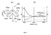
- sandwiching rollers 231 and 232 constituting a pair of sandwiching rollers 230 are all formed as truncated conical rollers. That is, in the sandwiching rollers 231 and 232 of the second embodiment, the shape of the large diameter side is the same as that of the sandwiching rollers 131 and 132 of the first embodiment, but the small diameter side is shortened. Since the other configurations are the same as those of the first embodiment, the same reference numerals are given thereto, and the specific description thereof will not be repeated.
- FIGS. 9A to 9C respectively correspond to FIGS. 3A to 3C.
- the ratio of the width of the contact portion with respect to the entire conical contact portion shown in FIG. 11A : W/W max is 50%.
- the stretching action with respect to the flexible substrate 1 is basically the same, but the conveying resistance Qx may be easily decreased.
- FIG. 9C illustrating the action of the sandwiching roller 231 (232) according to the second embodiment
- FIG. 3C illustrating the action of the sandwiching roller 131 (132) of the first embodiment
- the shape of the large diameter side is the same. Accordingly, the movement orbits of the substantial sandwiching points L1 and L2 are the same, whereby the tensile force Qy with respect to the flexible substrate 1 is basically the same.
- the sliding action (S0-S1) at the small diameter side decreases and the conveying resistance Qx largely decreases in accordance with a decrease of a difference in circumferential length between the large diameter side and the small diameter side.
- FIG. 11 illustrates a relation between the width W (the ratio of the width of the contact portion with respect to the width of the entire conical contact portion: W/W max ) of the contact portion, the tensile force Qy, the conveying resistance Qx when the inclination angle of the contact portion of the sandwiching roller is constant.
- W/W max the width of W (the ratio of the width of the contact portion with respect to the width of the entire conical contact portion: W/W max ) of the contact portion, the tensile force Qy, the conveying resistance Qx when the inclination angle of the contact portion of the sandwiching roller is constant.
- W/W max is 100%, and W decreases and the value of W/W max decreases in accordance with the truncated degree.
- the tensile force Qy a tendency is found in which the tensile force Qy increases as the width W of the contact portion between the sandwiching rollers 231 and 232 and the flexible substrate 1 is shortened due to an increase in pressure at the sandwiching surface.
- the tensile force Qy remarkably increases around the position where the line indicating the tensile force Qy and the line indicating the conveying resistance Qx intersect each other and a decreasing amount in the ratio of the width of the contact portion with respect to the width of the entire conical contact portion: W/W max becomes more than 60%.
- the control width of controlling the tensile force Qy also decrease when the width W of the contact portion is extremely narrow, it is desirable that the width W of the contact portion be from 30% to 60% of the width W max of the entire conical contact portion.
- FIGS. 13 and 14 illustrate embodiments in which a position controller for substrate 200a is configured by applying the position controller for substrate 200 of the second embodiment to a continuous film forming type thin film laminated body manufacturing apparatus 112.
- a position controller for substrate 200a is configured by applying the position controller for substrate 200 of the second embodiment to a continuous film forming type thin film laminated body manufacturing apparatus 112.
- an electrode 25 (target) and a ground electrode 26 having a heater embedded therein are disposed to face each other with the flexible substrate 1 interposed therebetween.
- the electrode 25 and the ground electrode 26 are fixed to the flexible substrate 1 with a predetermined gap, and continuously form a film in a non-contact state.
- the film forming region on the flexible substrate 1 is not segmented by the conveying direction, and rolls 23 and 23 are disposed at the upstream and the downstream in the conveying direction of the film forming unit 24 so as to guide the flexible substrate 1.
- the continuous film forming type manufacturing apparatus 112 is mainly used to stretch the flexible substrate in the lateral direction so as to suppress wrinkles generated in the flexible substrate 1 due to a tensile force and heat rather than the drooping of the flexible substrate 1 due to the gravity thereof. Then, as shown in the drawings, plural pairs of upper and lower sandwiching rollers 230 and 230' are arranged in series at the upper and lower portions of the film forming unit 24.
- a plurality of support rollers 27 are disposed in series along the conveying direction between the electrode 25 and the pair of upper and lower sandwiching rollers 230 and 230', and each pair of sandwiching rollers 230 and 230' is disposed outside the electrode 25.
- Each support roller 27 is desirably formed as a metallic roller with satisfactory heat resistance, and is rotatably supported to a shaft protruding from the lower surface of the bracket 28.
- the bracket 28 is fixed to a fixed support member 241, but may be fixed to the electrode 25.
- the position controller for substrate according to the invention is applied to the thin film laminated body manufacturing apparatus forming a film while conveying the flexible substrate 1 in the lateral direction in the longitudinal attitude.
- the position controller for substrate according to the invention may be applied to various processing apparatuses or manufacturing apparatuses forming a film while conveying the flexible substrate 1 in the lateral attitude (horizontal attitude) in the horizontal direction, the vertical direction, or the inclined direction.
- FIG. 15 is a cross-sectional view illustrating an embodiment in which a position controller for substrate 300 which is the same as that of the second embodiment of the invention is applied to a continuous film forming type manufacturing apparatus 312 conveying a substrate in a lateral attitude when seen from the upstream in the conveying direction.
- a film forming unit including an electrode 325 (target) and a ground electrode 326 disposed at the upper and lower sides to face each other with the flexible substrate 1 interposed therebetween is disposed inside a vacuum chamber maintained at a constant vacuum degree.
- the position controller for substrate of the thin film laminated body manufacturing apparatus 312 includes two position controller for substrates 300 and 300 that are disposed in the lateral direction at both sides in the conveying path of the flexible substrate 1. Since two position controller for substrates 300 and 300 basically have the same structure as that of the position controller for substrate 200 of the second embodiment except that a fixed sandwiching roller 331 (a fixed support member 341) is disposed at the lower side in the lateral direction, any side is provided with an actuator 366 and a sensor 367, a pressing force is actively controlled by a spring 350, and a movable support member 342 is swingably connected to a fixed support member 341 serving as a bracket, the same reference numerals are given to the same components, and the components will not be specifically described.
- the ground electrode 326 is disposed at the lower surface side of the flexible substrate 1, and the influence of the gravity of the flexible substrate 1 is small and is the same at each of the position controller for substrates 300 and 300. Therefore, the control amount of the actuator 366 and the initial displacement of the spring 350 and 350 are set to be basically the same in the position controller for substrates 300 and 300.
- each sensor 367 may include two detectors disposed adjacent to each other in the lateral direction to correspond to the maximal value and the minimal value allowed for each edge position of the flexible substrate 1, or each sensor 367 may be configured as one image sensor to detect each edge position of flexible substrate 1 by image processing.
- a stretching spring is used as a pressing means, but may be configured as a compressing spring by appropriately changing the connection point with respect to the fixed and movable support members, each link, and the movable shaft.
- an arm portion or the like may be additionally provided in each of the fixed or movable support member, each link, or the movable shaft if necessary.
- the coil spring may be changed as various general springs such as a spiral spring, a torsion spring, and a leaf spring.
- the fixed and movable support members and the links may move close to or away from each other by a linear sliding movement, but the swinging movement (pivoting movement) is desirable from the viewpoint of efficiency.
- the position controller for substrate according to the invention is applied to the thin film laminated body manufacturing apparatus for the solar cell.
- the position controller for substrate of the invention may be, of course, applied to an apparatus that manufactures a semiconductor thin film such as an organic EL, and various processing apparatuses related to coating, cleaning, drying, heat-treatment, surface processing, and the like that require the positional control or the stretching operation of the flexible substrate in addition to film forming.
Landscapes
- Chemical & Material Sciences (AREA)
- Engineering & Computer Science (AREA)
- Mechanical Engineering (AREA)
- Metallurgy (AREA)
- Materials Engineering (AREA)
- Chemical Kinetics & Catalysis (AREA)
- Organic Chemistry (AREA)
- General Chemical & Material Sciences (AREA)
- Registering, Tensioning, Guiding Webs, And Rollers Therefor (AREA)
- Photovoltaic Devices (AREA)
- Physical Vapour Deposition (AREA)
- Chemical Vapour Deposition (AREA)
- Electroluminescent Light Sources (AREA)
Applications Claiming Priority (3)
| Application Number | Priority Date | Filing Date | Title |
|---|---|---|---|
| JP2010026502 | 2010-02-09 | ||
| JP2010162704A JP5652700B2 (ja) | 2010-02-09 | 2010-07-20 | 可撓性基板の位置制御装置 |
| PCT/JP2010/072987 WO2011099227A1 (fr) | 2010-02-09 | 2010-12-21 | Dispositif de contrôle de position pour substrat souple |
Publications (2)
| Publication Number | Publication Date |
|---|---|
| EP2535439A1 true EP2535439A1 (fr) | 2012-12-19 |
| EP2535439A4 EP2535439A4 (fr) | 2014-01-08 |
Family
ID=44367518
Family Applications (1)
| Application Number | Title | Priority Date | Filing Date |
|---|---|---|---|
| EP10845817.5A Withdrawn EP2535439A4 (fr) | 2010-02-09 | 2010-12-21 | Dispositif de contrôle de position pour substrat souple |
Country Status (5)
| Country | Link |
|---|---|
| US (1) | US8746309B2 (fr) |
| EP (1) | EP2535439A4 (fr) |
| JP (1) | JP5652700B2 (fr) |
| CN (1) | CN102575342A (fr) |
| WO (1) | WO2011099227A1 (fr) |
Families Citing this family (10)
| Publication number | Priority date | Publication date | Assignee | Title |
|---|---|---|---|---|
| JP5488997B2 (ja) * | 2010-06-17 | 2014-05-14 | 富士電機株式会社 | 薄膜積層体製造装置の基板位置制御装置 |
| JP5787216B2 (ja) * | 2010-06-24 | 2015-09-30 | 富士電機株式会社 | 薄膜積層体製造装置およびその運転方法 |
| JP6086628B2 (ja) * | 2013-04-18 | 2017-03-01 | 富士機械製造株式会社 | 基板クランプ装置 |
| CN104016171A (zh) * | 2014-06-11 | 2014-09-03 | 永新股份(黄山)包装有限公司 | 一种膜卷收卷用锁边夹持器 |
| CN104977815B (zh) * | 2015-07-03 | 2018-02-23 | 苏州微影激光技术有限公司 | 直写式曝光系统中的扫描台 |
| KR101650398B1 (ko) * | 2015-09-11 | 2016-08-24 | (주)코맷 | 계측기용 웨이퍼 센터링 디바이스 |
| CN108011576A (zh) * | 2017-12-31 | 2018-05-08 | 正信光电科技股份有限公司 | 一种光伏组件的边框 |
| US11177412B2 (en) * | 2019-04-22 | 2021-11-16 | Beijing Apollo Ding Rong Solar Technology Co., Ltd. | Sputter deposition apparatus including roller assembly and method |
| CN111276435B (zh) * | 2020-03-19 | 2022-04-15 | 中国科学院苏州生物医学工程技术研究所 | 宽范围、均匀应变的柔性电子基底近圆式拉伸系统 |
| CN118497686B (zh) * | 2024-06-07 | 2025-06-20 | 深圳市腾他抗菌纺织品有限公司 | 一种钛铜抗菌防护隔离布的生产装置及方法 |
Family Cites Families (13)
| Publication number | Priority date | Publication date | Assignee | Title |
|---|---|---|---|---|
| US3147898A (en) * | 1962-07-10 | 1964-09-08 | William F Huck | Transverse web control devices |
| US4068789A (en) * | 1975-10-24 | 1978-01-17 | Young Engineering, Inc. | Method and apparatus for controlling a moving web |
| CH643485A5 (en) | 1979-12-17 | 1984-06-15 | Berthold & Guettinger Ag | Apparatus for transporting and guiding a tape-like photographic recording medium in a photosetting machine |
| US4726807A (en) * | 1986-04-10 | 1988-02-23 | Weyerhaeuser Company | Diaper with elastic margins |
| CA2137347A1 (fr) * | 1992-08-11 | 1994-03-03 | Per Just Andersen | Contenants a prise hydraulique |
| US6902053B1 (en) | 2003-10-14 | 2005-06-07 | Rodney Long | Conveyor belt alignment system |
| JP2007250681A (ja) * | 2006-03-14 | 2007-09-27 | Matsushita Electric Ind Co Ltd | 半導体樹脂封止装置及びリリースフィルムの供給方法 |
| DE102006033354B4 (de) * | 2006-07-19 | 2012-01-12 | Höllmüller Maschinenbau GmbH | Vorrichtung zum Behandeln von flachen, zerbrechlichen Substraten |
| JP2008117889A (ja) * | 2006-11-02 | 2008-05-22 | Dainippon Screen Mfg Co Ltd | 基板処理装置 |
| JP2009057632A (ja) | 2007-08-03 | 2009-03-19 | Fuji Electric Holdings Co Ltd | 薄膜積層体の製造装置 |
| JP2009038277A (ja) | 2007-08-03 | 2009-02-19 | Fuji Electric Systems Co Ltd | 薄膜積層体の製造装置 |
| JP2009038276A (ja) * | 2007-08-03 | 2009-02-19 | Fuji Electric Systems Co Ltd | 薄膜積層体の製造装置 |
| WO2009122836A1 (fr) * | 2008-03-31 | 2009-10-08 | 富士電機システムズ株式会社 | Equipement et procédé de production de stratifiés à films minces |
-
2010
- 2010-07-20 JP JP2010162704A patent/JP5652700B2/ja not_active Expired - Fee Related
- 2010-12-21 WO PCT/JP2010/072987 patent/WO2011099227A1/fr not_active Ceased
- 2010-12-21 EP EP10845817.5A patent/EP2535439A4/fr not_active Withdrawn
- 2010-12-21 US US13/381,051 patent/US8746309B2/en not_active Expired - Fee Related
- 2010-12-21 CN CN201080032145XA patent/CN102575342A/zh active Pending
Also Published As
| Publication number | Publication date |
|---|---|
| EP2535439A4 (fr) | 2014-01-08 |
| US8746309B2 (en) | 2014-06-10 |
| WO2011099227A1 (fr) | 2011-08-18 |
| CN102575342A (zh) | 2012-07-11 |
| US20120291958A1 (en) | 2012-11-22 |
| JP5652700B2 (ja) | 2015-01-14 |
| JP2011184794A (ja) | 2011-09-22 |
Similar Documents
| Publication | Publication Date | Title |
|---|---|---|
| US8746309B2 (en) | Position controller for flexible substrate | |
| US20120031565A1 (en) | Flexible substrate position control device | |
| JP5201490B2 (ja) | 可撓性基板の処理装置および薄膜積層体の製造装置 | |
| EP2514852A1 (fr) | Dispositif de transport pour un substrat formant film | |
| JP5423808B2 (ja) | 可撓性基板の搬送装置 | |
| JP2009038276A (ja) | 薄膜積層体の製造装置 | |
| JP2009057632A (ja) | 薄膜積層体の製造装置 | |
| JP2009038277A (ja) | 薄膜積層体の製造装置 | |
| EP2463402A1 (fr) | Appareil pour laminage d un film mince | |
| JP2016216249A (ja) | ウエブ搬送装置 | |
| JP2010177343A (ja) | 薄膜積層体の製造装置 | |
| JP5126088B2 (ja) | 薄膜積層体の製造装置 | |
| JP2012099606A (ja) | 可撓性基板の展張装置 | |
| WO2011077901A9 (fr) | Dispositif de fabrication de stratifié à couches minces | |
| JP2011032555A (ja) | 薄膜積層体製造装置の基板位置制御装置 | |
| JP2011146437A (ja) | 可撓性基板の位置制御装置 | |
| JP2011032554A (ja) | 薄膜積層体製造装置 | |
| WO2010032530A1 (fr) | Corps structurel à film mince et procédé de fabrication de celui-ci | |
| TWI844850B (zh) | 用於避免輥對輥處理中的可撓基板的起摺、起皺、及變形的特殊輥的包括 | |
| JP5488997B2 (ja) | 薄膜積層体製造装置の基板位置制御装置 | |
| JP2010177344A (ja) | 薄膜積層体の製造装置 | |
| JP2010215371A (ja) | 帯状可撓性基板搬送システムおよびそれに用いる搬送位置制御装置 | |
| JP2013004727A (ja) | 帯状可撓性基板の案内装置 |
Legal Events
| Date | Code | Title | Description |
|---|---|---|---|
| PUAI | Public reference made under article 153(3) epc to a published international application that has entered the european phase |
Free format text: ORIGINAL CODE: 0009012 |
|
| 17P | Request for examination filed |
Effective date: 20120208 |
|
| AK | Designated contracting states |
Kind code of ref document: A1 Designated state(s): AL AT BE BG CH CY CZ DE DK EE ES FI FR GB GR HR HU IE IS IT LI LT LU LV MC MK MT NL NO PL PT RO RS SE SI SK SM TR |
|
| DAX | Request for extension of the european patent (deleted) | ||
| A4 | Supplementary search report drawn up and despatched |
Effective date: 20131211 |
|
| RIC1 | Information provided on ipc code assigned before grant |
Ipc: H01L 21/67 20060101ALI20131205BHEP Ipc: H01L 21/205 20060101ALI20131205BHEP Ipc: C23C 16/54 20060101ALI20131205BHEP Ipc: H01L 21/677 20060101ALI20131205BHEP Ipc: C23C 14/56 20060101ALI20131205BHEP Ipc: H01L 31/20 20060101ALI20131205BHEP Ipc: H01L 31/04 20060101ALI20131205BHEP Ipc: C23C 16/44 20060101AFI20131205BHEP |
|
| STAA | Information on the status of an ep patent application or granted ep patent |
Free format text: STATUS: THE APPLICATION HAS BEEN WITHDRAWN |
|
| 18W | Application withdrawn |
Effective date: 20140430 |