EP2535472A2 - Support pour matière isolante - Google Patents
Support pour matière isolante Download PDFInfo
- Publication number
- EP2535472A2 EP2535472A2 EP12171942A EP12171942A EP2535472A2 EP 2535472 A2 EP2535472 A2 EP 2535472A2 EP 12171942 A EP12171942 A EP 12171942A EP 12171942 A EP12171942 A EP 12171942A EP 2535472 A2 EP2535472 A2 EP 2535472A2
- Authority
- EP
- European Patent Office
- Prior art keywords
- insulating
- insulation
- end portion
- holder
- side end
- Prior art date
- Legal status (The legal status is an assumption and is not a legal conclusion. Google has not performed a legal analysis and makes no representation as to the accuracy of the status listed.)
- Granted
Links
Images


Classifications
-
- E—FIXED CONSTRUCTIONS
- E04—BUILDING
- E04B—GENERAL BUILDING CONSTRUCTIONS; WALLS, e.g. PARTITIONS; ROOFS; FLOORS; CEILINGS; INSULATION OR OTHER PROTECTION OF BUILDINGS
- E04B1/00—Constructions in general; Structures which are not restricted either to walls, e.g. partitions, or floors or ceilings or roofs
- E04B1/18—Structures comprising elongated load-supporting parts, e.g. columns, girders, skeletons
- E04B1/26—Structures comprising elongated load-supporting parts, e.g. columns, girders, skeletons the supporting parts consisting of wood
- E04B1/2604—Connections specially adapted therefor
- E04B1/2612—Joist hangers
Definitions
- the invention relates to an insulation holder, an arrangement and a method for connecting an insulation holder with an insulating element.
- Under a formwork is understood to mean a mold into which fresh concrete for the production of concrete components is introduced. After hardening of the concrete, it is usually removed. Conventionally, in the manufacture of concrete walls by means of shuttering an insulation or insulation wall is connected to the concrete.
- DE 10324760 discloses a wall element with two spaced apart concrete layers, with an insulating layer, which is assigned to one of the two concrete layers, wherein between the insulation layer and the other concrete layer for filling with in-situ concrete a gap is provided, and with a plurality of the two concrete layers connecting connecting elements, wherein the Connecting elements extend from the one concrete layer through the insulating layer and the gap through to the other concrete layer. It is provided at least one connecting means, which extends from a concrete layer optionally through the insulating layer only up into the gap.
- DE 29705044 discloses a building construction element.
- DE 69516864 discloses highly insulating tie bars and methods for their manufacture and use in highly insulated composite walls.
- DE 7018445 discloses a multi-layer concrete slab with a connecting needle provided therein.
- EP 1,449,977 discloses a ventilating device for reinforced concrete components, comprising closed cavities or weight-reducing elements.
- an insulation holder (which may also be referred to as shuttering anchors) for connecting an insulating element is provided with a building element to be cast, wherein the insulation holder a Dämmstoffelement facultyen end portion which is formed for insertion into the insulating element (in particular shaped) to to anchor there, a structural member side end portion opposite to the insulating member side end portion and formed for pouring into the building element, and having an anchoring depth mark indicating an anchoring depth up to which insertion of the insulating member side end portion into the insulating member is to be performed.
- this Vor Principle take place such that upon insertion of the insulating material-side end portion in the insulating element up to the anchoring depth a Dämmstoffelement workedes End (in particular an end tip) of the insulating element-side end portion is completely sunk or anchored only in the interior of the insulating element (ie without penetrating through both opposite walls of the insulating element).
- An insulating holder for bonding an insulating member to a structural member to be cast comprises a insulating member-side end portion adapted to be inserted into the insulating member to anchor there, and a structural-member-side end portion facing the insulating-member-side end portion; and which is designed for pouring into the building element.
- Such an exemplary embodiment of the invention thus comes without anchoring depth mark and can be provided with any, described in the context of this application feature of insulation holder.
- such an insulation holder can be equipped with any feature or with any feature combination of the dependent claims.
- an arrangement which comprises an insulating element and an insulating holder for connecting the insulating element with a building element to be cast.
- This insulating holder has a Dämmscherlement solutionen end portion which is adapted to be inserted into the insulating element to anchor there, and a building element side end portion which faces the Dämm fürlement facultyen end portion and which is formed for pouring into the building element, wherein the insulating element-side end portion in the insulating element is inserted (or is insertable) to an anchoring depth, wherein the structural element-side end portion protrudes from the insulating element.
- the insulating element-side end portion may be arranged in the interior of the insulating element, in particular such that a free end of the insulating material side End portion is anchored or arranged in the interior of the insulating element.
- a method of bonding an insulation holder to an insulation member wherein the insulation holder has a structural member-side end portion and an opposing insulation-member-side end portion, wherein in the method, the insulation member-side end portion of the insulation holder is inserted into the insulation element to an anchoring depth is, in which the building element-side end portion protrudes from the insulating element for pouring into the building element and the insulating element-side end portion is anchored in the interior of the insulating element.
- an "insulating element” can be understood in particular to mean a structure (for example a wall, a panel or another body) made of a thermal insulating material, such as a house, made of insulating material and to be produced by means of casting Building element to be connected.
- a thermal insulating material such as a house
- Such an insulating element may have a wall thickness of, for example, 1 cm to 10 cm or more, in particular 2 cm to 5 cm.
- a pressure-resistant, foam-like plastic can be used as a material for the insulating element.
- a suitable material for the insulating element has a sufficiently high density in order to allow good thermal insulation (and possibly sound insulation).
- a suitable material for the insulating element is polystyrene (poly (1-phenylethane-1,2-diyl)), which is also commercially available under the name Styrodur.
- polystyrene poly (1-phenylethane-1,2-diyl)
- Styrodur poly(ethylene glycol)
- PU polyurethane
- the insulation boards described have standardized dimensions in the rule.
- a "structural element” can be understood in particular as a component or cast component of a structure to be cast, for example, by pouring liquid building material (for example concrete or screed) into a cavity, in particular between an insulating element and a formwork can be. This liquid building material subsequently hardens and then forms the building element.
- a structure associated with the building element can be a building, such as a house, or else a different structure, such as a bridge or a tunnel.
- a "Dämmscherlement facultyen end portion" of the insulation material holder in particular a structural direction in the insertion front end of the insulation material holder are understood, which is shaped and configured to be able to penetrate into the insulating element, in particular to penetrate cutting. This penetration can be done manually with the exclusive exercise of muscle power or by means of a corresponding tool, such as a hammer.
- a "structural element-side end portion" of the insulation holder in particular a structural insertion in the rear end of the insulation holder, which protrudes as intended in the assembled state of the insulation holder against the insulating element and thus forms an anchor in the cast or cast material of the building element.
- an “anchoring depth marking” can be understood in particular as any structural or otherwise perceptible feature (for example a color marking) which indicates to a user or which is imperative by its handling or properties when inserted into an insulating element leads to (for example, acting as a mechanical barrier) that the insertion of Dämmstoffelement Fabricen End section only up to a certain anchoring depth should, may or may.
- the anchoring depth mark can be an insertion lock, which, for example, positively or non-positively prevents it, that an insulation holder is further introduced as desired in an insulating element.
- the anchoring depth marking can also be merely a visual or haptic marker on the basis of which a user can recognize how deep the insulation holder may or should be inserted into the insulating element.
- the position of a stroke on the insulation holder may indicate up to what maximum depth or anchorage depth the insulation holder is to be inserted into the insulation element and anchored therein at a suitable location or depth.
- an insulating material holder can be used in such a way that it is inserted into the insulating element from the structural element side, possibly subsequently.
- the attachment can be made in such a way that the insulation holder emerges only structural element side (for example, concrete wall side) of the insulating element and is sunk completely with its other end in the interior of the insulating element, so that between the dämmstoffelement facultyen end portion of the insulating material holder and the free surface of the insulating element a buffer of insulating material remains. This has the consequence that on the other side of the insulating element, ie on the side facing away from the concrete wall, no disturbing parts of the insulation holder stand out.
- the insulation holder may have an end stop surface as the anchorage depth mark between the insulation element side end portion and the structural member end portion which abuts a surface of the insulation member upon insertion of the insulation holder up to the anchoring depth (defined by the position of the end stop surface). ie with respect to the maximum or anchoring depth continued) insertion of the insulation holder is prevented in the insulating element and the structural element-side end portion protrudes from the insulating element (ie remains outside of the insulating element, while the insulating element-side end portion is sunk within the insulating element).
- an "end stop surface” can be understood as meaning a structure having a particularly two-dimensional bearing surface which is configured, shaped and aligned in such a way that, when the intended purpose of the invention is introduced Insulating material holder in the insulating element, the end stop surface in an associated end position abuts against a corresponding mating surface of the insulating element surface, whereby further insertion of the insulating material holder inhibited and an alignment of the insulating material holder is adjusted relative to the insulating element.
- the end stop surface forms a barrier to the insertion of the insulation holder in the insulating element beyond a maximum depth.
- the insulating element-side end portion undesirably passes through a second surface of the insulating element due to an uncontrolled deep penetration into the insulating element, which is opposite to the building element side surface of the insulating element.
- the insulating material holder may have an expanding mechanism, which is set up when the insulating-material-side end section is inserted into the insulating element for spreading in the insulating element in order to anchor itself there.
- an "expanding mechanism” is understood to mean, in particular, a structure of mechanically interacting components which, owing to the forces acting upon insertion of the insulating material holder into the insulating element, result in wedging (in particular lateral) of at least one physical structure in the insulating element, i. at an angle to an insertion direction.
- the insulation holder may have a Verspreizanscher phenomenon (which is spatially separated from the end stop surface), which upon insertion of the insulating element side end portion in the insulating element upon reaching a desired depth (which is usually less than the maximum depth) for abutment with a boundary surface of the insulating element is designed.
- the expanding mechanism may be arranged to continue the insertion of the insulating material side End section in the insulating element after reaching the desired depth (to reach the maximum depth) to cause the spreading in the insulating element.
- the term “desired depth” is understood to mean, in particular, a distance between the insulation element-side end section of the insulation holder and the expansion stop surface, which essentially corresponds to a length along which the insulation holder is inserted into the insulation element until the spreading mechanism is triggered.
- an insulating material holder is thus provided, which is placed on an insulating element and pressed into it. This pressing movement is continued until a support surface of the insulation holder rests on the insulating element.
- spreading structures detach from the insulation holder and are spread open by a spreading edge, whereby an undercut is formed.
- the insulation holder may have a cutting edge body for cutting the insulating-material-side end section into the insulating element.
- a "cutting edge body” is understood in particular to mean a component or a component which, when pressed into the insulating element with at least one cutting edge, cuts the insulating element.
- the cutting edge body may also be referred to as a knife.
- a simple and possibly retrofittable and cost-producible aid is thus created, which can be inserted manually or with a tool in an insulating element and makes use of the cutting action of the correspondingly configured cutting edge body use.
- the cutting edge body may have an arrow-shaped front area.
- a guide tip for specifying a penetration direction can be provided, but also the force be kept low for introducing the insulation holder in the insulating element.
- the cutting edge body may have two mutually angled cutting edges converging in a point.
- the tip can serve as a starting point for accurately positioning the insulation holder.
- the angle that the two angled cutting edge regions can enclose may be an obtuse angle.
- this angle may be in a range between 100 ° and 150 °.
- the cutting edge body may have four mutually angled cutting edges converging in two separate tips. Between the tips, a recess or recess may be formed. Such a geometry allows a particularly well-directed and low-force insertion of the insulation holder.
- the cutting edge body may have an undercut (in particular behind the arrow-shaped cutting edges, for example) with an undercut.
- an undercut in particular behind the arrow-shaped cutting edges, for example
- a sliding rail for the triggering of the spreading mechanism can be provided, along which spreading elements can be guided to effect the spreading.
- the cutting edge body may be formed as a cutting plate.
- a plate may be designed as a correspondingly shaped thin sheet or as a correspondingly shaped plastic plate, which leads to a low-cost manufacturing at low cost.
- the cutting edge body may have a V-shaped or a W-shaped front region.
- a V-shaped Front portion has a tip, whereas a W-shaped front portion has two peaks with an intermediate V-shaped recess.
- the straddle abutment surface may be formed as a major surface (i.e., one of two opposing plate planes) of an abutment plate, the major surface being orthogonal to an insertion direction of the insulator-element-side end portion into the insulator element and / or orthogonal to a cutting edge body formed as a cutting plate.
- a plastic or metal plate may be aligned perpendicular to the intended insertion direction, so that upon insertion of the insulation material holder in a wall-like trained insulating element, the main surface presses against a flat surface of the insulation board, which causes a desired orientation of the insulation material holder relative to the insulating element ,
- the expanding mechanism can have two or more spreading structures (possibly also a single spreading structure), in particular expansion legs or spreading rails.
- the expansion leg can limit the insulation holder laterally and be set up for guided insertion of the insulation holder in the insulating part.
- These two opposing spreading structures which may be formed, for example, as guide rails or as plate-like sections, simplify the actuation of the insulation material holder, since they are aligned (before spreading) along a designated insertion direction.
- insulating-material-side end sections of the spreading structures may protrude beyond the spreading stop surface in the insertion direction and be set back relative to a cutting edge body.
- the cutting edge body thus defines the position of the first incision of the insulating material holder in the insulating element, wherein the end portions of the spreading structures only then dip into the insulating element and thus earlier in the movement with the insulating element come into contact as the stop plate.
- the insulating element-side end sections of the spreading structures can each be made to converge in an acute manner for insertion into the insulating part.
- the spreading structures contribute to the cutting action or their introduction into the insulating element can be made power arm.
- the spreading structures may have expansion legs for bracing the insulation holder in the insulation element during insertion of the insulation holder into the insulation part.
- the expansion legs can solve at (beyond the desired depth) continued insertion and continued pressure on the insulation holder.
- these expansion legs can be spread apart by a (in particular rear) spreading edge of the cutting edge body along a correspondingly predeterminable trajectory and can thereby form an undercut. The bearing surface of the expansion limbs, i. the Endanschlag measurements, can then rest on the insulating element.
- the spreading structures and the Verspreizantsch requirements may be formed or arranged relative to each other to limit a receiving cavity for receiving material of the building element during its casting.
- the rear portion of the insulation material holder is formed hollow, in the later formation of the building element, in particular by casting concrete in formwork construction, penetration of the still liquid building material of the building element in the insulation holder allows. After curing of the material, this thus forms a firm connection with various components of the insulation holder and thus ensures a secure connection between structural element and insulation holder.
- the insulation holder a cover element, in particular a flat cover plate (in particular formed as a circular disk), at a rear end portion in the insertion direction.
- a back cover plate makes it possible to close the receiving space for material of the building element at least partially back. At the same time can be avoided by closing on the back of the insulation holder unwanted hooking with components, for example, a reinforcement.
- the cover element may have a reinforcement fastening structure, in particular one or more through holes.
- the reinforcement attachment structure may be configured to attach a reinforcement. If a reinforcement is to be fastened to the insulating material holder, then one or more fastening structures can be provided for this purpose on the cover element, for example through-holes for wiring such a reinforcement. Instead of drilling other fastening devices such as projections for engaging the reinforcement can be provided.
- the insulation holder may be formed as a one-piece or integral component, in particular as a single-component (i.e., made of a single material) component, in particular as a plastic component. It is possible, for example, to produce the insulation holder as an injection molded part. In this way, the insulation holder can be manufactured inexpensively.
- the insulation holder can be formed as a simple plastic part or metal part.
- the cutting edge body and the Verspreizantsch requirements may be formed as a common rigid body against which the spreading structures are displaced upon overcoming a predetermined threshold force.
- this rigid body may be formed of two orthogonal plates and have a T-shaped structure in cross section.
- the spreading structures can be mounted in relation to the cutting edge body in such a way that when a relative movement takes place between the cutting edge body and On the other hand, the spreading stop surface on the one hand and the spreading structures on the other hand slide off the spreading structures along a section of the cutting edge body widening in the insertion direction and are thereby spread open. At least one of the spreading structures can have an end stop surface which strikes a surface of the insulating element when the relative movement between the cutting edge body and the spreading stop surface on the one hand and the spreading structures is continued beyond the desired depth, thereby preventing further insertion of the insulating material holder into the insulating element.
- the rigid body may be connected to the spreading structures by means of a predetermined breaking element, in particular by means of a film hinge, wherein the predetermined breaking element is arranged to break upon overcoming the predefinable threshold force.
- a predetermined breaking element acts as a predetermined breaking point and can be dimensioned so that when exceeding a force exerted after reaching the desired depth with continued movement of the insulation holder, the connection between the spreader and the rigid body is destroyed defined, whereby the spreading structures along the rigid body can slide off and thus trigger the spread.
- the predetermined breaking element may be, for example, a thin web or a film hinge.
- the film hinge can consist of a thin-walled connection, for example in the form of a fold, which allows by its flexibility limited rotational movement of the connected parts.
- a material suitable for this purpose is polypropylene.
- the spreading structures can have at least one latching element (for example a total of two or four latching elements on opposite inner surfaces of the spreading structures), which is set up for latching the rigid body to the spreading structures.
- latching structures can trigger or activate the latching action upon insertion of the insulating material holder up to the maximum depth, in that the latching device engages the rigid body only at or near the maximum depth.
- locking elements may be formed, for example in the form of locking lugs on an inner surface of the two spreading structures. If the rigid body slides upwardly along the spreading structures relative to these, the spreading structures will continue to move into the insulating element in the direction of insertion and simultaneously spread laterally therefrom. Finally, the rigid body between the locking lugs of the expansion structures engage, so that an unwanted extraction of the insulation holder can be avoided from the insulating element.
- the building element-side end portion may have two opposite (preferably identical or mirror-image) clamping wings into which a tool (for Example, a hammer) for inserting the insulation holder in the insulating element temporarily clamped - ie releasably clamped - is.
- a tool for Example, a hammer
- Such feathery, elastic clamping wings thus advantageously support a tool-based insertion process of the insulation holder.
- such an insulation holder is compatible with reinforcements that are to stabilize a concrete wall to be cast. Because while conventional insulation holder can be damaged by such reinforcements, damage due to a reinforcement is avoided due to the resilient properties of the clamping wing.
- the clamping wings may have mutually facing leaf spring-like indentations. These indentations may be U-shaped, the round sections may face each other. These clamping wings form undercuts at least in sections (in particular with respect to an insertion direction of the insulating material holder) so that the insulating material holder is reliably held in the concrete or in order to achieve a good anchoring.
- the tensioning wings can be mechanically weakened, in particular laterally tapered, in their spring-like section.
- the clamping wings can be equipped with a particularly high flexibility in the resilient central portion.
- the clamping wings can have bulges which define a maximum penetration depth of the insulating material holder into the insulating element.
- a boundary between the insulating member side end portion and the structural member side end portion may be defined by the protrusions.
- a lower horizontal portion of the bulges can clearly serve as a stop on the insulating element.
- the arrangement may further comprise the building element, in particular formed as a concrete part.
- the insulation holder may be at least partially cast in the building element.
- the building element can in particular a building part (Wall, ceiling, etc.), such as a concrete wall, or may be part of another structure such as a tunnel, bridge or the like.
- the arrangement may further comprise a reinforcement, which may be arranged in the building element, in particular fastened to the insulation holder.
- a reinforcement or reinforcement can be a component for reinforcing the building element, which component has a higher compressive or tensile strength or greater durability against further environmental influences (water, frost, chemical substances, etc.) than the building element.
- a steel reinforcement can be inserted to accommodate the tensile forces or additional compressive forces to form reinforced concrete.
- the method can furthermore be designed for connecting the insulating element to a structural element to be cast by means of the insulating material holder and furthermore comprising the step of casting the structural element such that it at least partially covers the protruding part of the structural element-side end section, so that by means of the insulating material holder Insulating element is connected to the cast building element.
- an insulation holder is provided. This is actuated such that a knife is placed on an insulating element such as an insulating Dämmstoffwand and the insulation holder is pressed into place at the point of this knife in the insulating element. This pushing movement is continued until a set-back bearing surface of the knife rests on the insulation. When exerting a further compressive force spreader leg of solve the knife and are spread by a Aufsp Dr Drssenkante. An even more rear bearing surface of the expansion leg is then on the insulation. After an optional setting of a reinforcement concrete is poured. Eventually, the reinforcement can be mounted on the head of the expansion leg.
- an insulating element such as an insulating Dämmstoffwand
- two holes may be formed in the head of the insulation holder to secure a wire reinforcement to the insulation holder.
- the reinforcement can be placed in front of the insulation holder and fixed with a wire through the holes on the insulation holder.
- a corresponding insulation holder can be made entirely of plastic. It is possible to provide detents which hold the bearing surface of the blade (for example, a first or a second detent can be activated depending on the pressure). Different shapes are possible for tips of the expansion limbs, for example a V-shape or an angular shape. As a result, it can be adjusted whether, for example, a spreading force is applied to the outside.
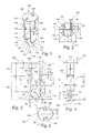
- the insulation holder 100 is formed as einstoffiges injection molded part made of plastic material and thus cost manufacturable.
- the insulation holder 100 has a Dämmstoffelement furnishen end portion 190, for insertion into an insulating plate (not shown in FIG. 1 ) is designed to anchor there. Further, the insulation holder 100 has a building element-side end portion 180, which faces the Dämm fürlement facultyen end portion 190 and the pouring into a concrete wall (not shown in FIG FIG. 1 ) is trained. Moreover, in the insulation holder 100, an anchoring depth mark is provided which indicates an anchoring depth up to which insertion of the insulating member side end portion 190 into the insulation board is to be performed. The anchoring depth marking is in the described embodiment as a visually clearly visible End stop surface 140 between the Dämmstoffelement remedyen end portion 190 and the structural element-side end portion 180 is formed.
- the end stop surface 140 strikes upon insertion of the Dämmstoffelement facultyen end portion 190 in the insulation board up to the anchorage depth to a surface of the insulation board, whereby further insertion of the insulation material holder 100 is prevented in the insulation board and the building element side end portion 180 for pouring into the concrete wall to be poured against the Insulation plate protrudes.
- the insulation holder 100 is for connecting an insulation board (not shown in FIG. 1 ), that is a thermal insulation wall of a building (for example made of foamed plastic), with a concrete wall to be cast by shuttering (not shown in FIG FIG. 1 ) set up.
- the insulation holder 100 has a cutting edge body 102 which is adapted to the cutting insertion of the insulation holder 100 in the insulation board.
- the cutting edge body 102 is inserted into the insulation board, whereby initially a plane cutting plane is formed in the insulation board, along which the plate-shaped cutting edge body 102 penetrates.
- the cutting edge body 102 is designed arrow-shaped and has two mutually obtuse angle cutting edges 106, 108.
- the cutting edges 106, 108 are linearly or rectilinearly arranged, but may alternatively be curved.
- the angled provision of the cutting edges 106, 108, these meet in a tip 110, which forms a insulation board side end of the cutting edge body 102.
- the cutting edge body 102 penetrates into the insulation board and cuts into the insulation board over a successively increasing lateral extent.
- the described configuration of the cutting edges 106, 108 and the flat formation of the cutting edge body 102 as a whole lead to a low-power operation.
- the insulating material holder 100 has a Verspreizanschlag phenomenon 104 as the lower main surface of a flat plate 114th made of plastic.
- the Verspreizanschlag tone 104 is integrally and rigidly formed with the cutting edge body 102 and is arranged so that upon insertion of the insulating material holder 100 in the insulation board upon reaching a desired depth d, which corresponds approximately to the distance between the tip 110 and the Verspreizantsch constitution 104, to a flat boundary surface of the insulation board flat abuts or abuts.
- the undercut section 112 designates the region of the cutting edge body 102 that is concavely curved in this exemplary embodiment, in which it merges inwards again behind the arrow-like divergence.
- This undercut section 112 has the function of leading a spreading of expansion limbs 116, 118 of the insulation holder 100 and thus accomplishing a reliable anchoring of the insulation holder 100 in the insulation board. This will be described below.
- the Verspreizantsch configuration 104 is arranged perpendicular to the main surface of the cutting edge body 102 and perpendicular to an insertion direction 175 of the insulating material holder 100.
- This geometry causes even with a slightly angular insertion of the insulation holder 100 by a user when resting the Verspreizantsch constitution 104 on a flat surface of the insulation board, the Verspreizantsch components 104 experiences an aligning force, due to which the Dämmstoffhalter 100 then plan with the Verspreizanscher characteristics 104 on the surface the insulation board is aligned.
- the insulation holder 100 has two mutually in the rest position according to FIG. 1 substantially parallel to each other arranged plate-like elongated expansion legs 116, 118 which limit the insulation holder 100 side and are set up for guided insertion of the insulation holder 100 in the insulation board.
- the expansion limbs 116, 118 extend beyond the Verspreizantschization 104 in the insertion direction 175, but are set back relative to the tip 110 of the cutting edge body 102.
- components 102, 104 move relative to components 116, 118, thereby introducing components 116, 118 farther deeper into the insulation panel, whereas due to the abutting straddle surface 104, components 102, 104 remain at a constant location relative to the insulation panel.
- the expansion limbs 116, 118 slide with respect to the body formed from the components 102, 104 and laterally brace when the spreading structures 116, 118 move along the concave undercut portion 112.
- the insulation holder 100 By this spreading movement, there is an anchoring of the insulation holder 100 in the insulation board.
- the expansion legs 116, 118 in the insulation board are formed at the end portions 120 which face the insulation board when used as intended, tapering more knives. Their geometric shape determines the insertion of the expansion legs 116, 118 in the insulation board.
- locking lugs 122 are formed on a respective inner surface of both expansion limbs 116, 118. Between each two of the locking lugs 122 of a spreader leg 116, 118, the Verspreizanscher phenomenon 104 locked. This undesirable loosening of the insulation holder 100 used is avoided by the insulating element.
- a cavity 124 is formed for subsequently receiving liquid concrete in the insulation holder 100.
- liquid concrete is poured into a space between a formwork part and the insulation board, the liquid concrete also fills the receiving space 124 with concrete, also the outside of the insulation holder 100 is cast around with concrete.
- a secure connection between the solidified concrete, the insulation board and the insulation holder 100 accomplished.
- a film hinge 300 (in particular perforated) is provided as a predetermined breaking element.
- the film hinge 300 ruptures when a predetermined minimum load is exceeded to allow a desired detachment of the tee 102, 104 from the expansion limbs 116, 118.
- this minimum load is exceeded, the integrity of the insulation holder 100 is overcome, and the insulation holder 100 is divided into the components 102, 104 on the one hand and into the components 116, 118 on the other hand.
- This minimum load is placed on the insulation holder 100 exerted when it is introduced to the desired depth d in the insulating element.
- a circular disk-shaped cover plate 126 is formed in a concrete wall-side end portion of the insulation holder 100, which has a maximum distance from the insulation board in the inserted state.
- this has two through holes 128, through which a wire can be passed, in order to connect a reinforcement, not shown in the figure, to the insulation holder 100.
- FIG. 2 to FIG. 5 show further, provided with purely exemplary dimensional information cross-sectional views of the insulation holder 100 according to the described exemplary embodiment.
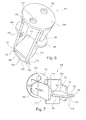
- FIG. 6 and FIG. 7 show other spatial views of the insulating body 100.
- FIG. 1 to FIG. 7 different embodiments of embodiments of the invention possible.
- an insulation holder 800 according to another exemplary embodiment is shown in FIG FIG. 8 shown free of holes 128 in the cover plate 126 for securing a reinforcement.
- the cover plate 126 is according to Fig. 8 formed as a continuous circular disk.
- FIG. 9 shows that after casting with liquid concrete, an insulation holder 900 according to another exemplary embodiment enables a secure connection between an insulation panel 902 and a concrete wall 904 formed by the casting.
- the anchoring of the insulation holder 900 is accomplished in the insulating plate 902, that a part of the surface of the insulation holder 900 is coated with an adhesive before it is introduced into the insulation plate 902.
- the friction between insulation holder 900 and insulation plate 902 may be sufficient to cause sufficient anchoring force.
- FIG. 9 shows that a Dämmscherlement remedyen end portion 190 of the insulating material holder 900 is disposed in the interior of the insulating plate 902 and the according to FIG. 9 left main surface of the insulating plate 902 not pierced.
- FIG. 9 shows that the end stop surface 140 is in contact with a surface 906 of the insulation board 902.
- FIG. 10 to FIG. 12 show different views obtained in a method of forming an assembly according to an exemplary embodiment of the invention.
- FIG. 10 shows a state in which an inventive insulation holder is inserted with a tip 110 in an insulating plate 902.
- a user applies a corresponding compressive force to insert the insulation holder 100 into the insulation board 902.
- the user can use the lid member 126 as an actuator.
- FIG. 11 shows a subsequent state in which the Verspreizanschlag composition 104 of the insulation holder with a surface 906th the insulating plate 902 comes into contact. A deeper insertion of the T-piece of cutting edge body 102 and Verspreizanschlag requirements 104 in the insulating plate 902 is no longer possible.
- components 102, 104, on the one hand, and expansion limbs 116, 118, on the other hand can be parts of a one-piece device, which are coupled by means of a predetermined breaking element.
- the predetermined breaking element can be configured in such a way that it is destroyed only when the Verspreizantschization 104 is struck against the insulating plate 902, since then the entire pressure force of the user between components 102, 104 on the one hand and expansion limbs 116, 118 acts on the other.
- the guide rails 116, 118 slide on the conically widened undercut portion 112 of the cutting edge body 102, thereby causing a lateral spreading of the expansion leg 116, 118 in the insulating plate 902, resulting in a transverse force and thus to secure anchoring of the insulation holder 100 in the insulating plate 902 leads.
- the insulation holder 100 After casting with liquid concrete (not shown), the insulation holder 100 allows a secure connection between the insulation plate 902 and the concrete wall 904.
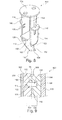
- FIG. 13 and FIG. 14 an insulation holder 1300 according to another exemplary embodiment of the invention described.
- FIG. 13 shows a cross-sectional view and FIG. 14 shows a side view of the insulation holder 1300th
- the insulation holder 1300 corresponds in many ways to the insulation holder 100 according to Fig. 1 , differs from this, however, especially with regard to the special features presented below.
- the building element-side end portion 180 has at the Dämmstoffhalter 1300 two opposing clamping jaws or clamping wings 1304, 1306, the Dämmscherlement question are interconnected by means of a flat connecting plate 1302 and are spaced building element side apart.
- the flexible and elastic clamping wings 1304, 1306 have free ends 1320, 1322 which are movable toward or away from each other when a force is exerted.
- the mutually mirror-symmetrical and arranged clamping wings 1304, 1306 have facing U-shaped leaf spring-like indentations 1308, 1310 on.
- the clamping wings 1304, 1306 are laterally tapered in the region of their leaf-spring-like indentations 1308, 1310, as in FIG Fig. 14 shown to increase the elasticity locally and thus to improve the clamping ability.
- the tensioning wings 1304, 1306 also have bulges 1312, 1314 which, together with the limiting plate 1302 connecting the bulges 1312, 1314, define a maximum penetration depth of the insulating material holder 1300 into an insulating element.
- Fig. 13 shows, each of the outwardly projecting free ends 1320, 1322 first in one of the recesses 1308, 1310 and the latter in the each associated with the bulges 1312, 1314 via, which are then connected to each other via the connecting plate 1302.
- the cutting edge body has a W-shaped front portion having two tips 110 with a V-shaped notch 1330 therebetween.
- the clamping wings 1304, 1306 can bend and then set up again.
- the tensioning wings 1304, 1306 are thus - in contrast to conventional holders - not destroyed.
- the clamping wings 1304, 1306 can thus be bent, then elastically erect or spring back and then still perform their function, i.
- the introduction of the anchor or insulation holder 1300 in the insulation or insulation board by the clamping wings 1304, 1306 can be facilitated. It is possible to temporarily clamp a hammer head with the clamping wings 1304, 1306, so that the entire anchor or insulating holder 1300 is held on the hammer.
- the anchor or Dämmstoffhalter 1300 can now be beaten easily with the aid of the hammer in the insulation or in the insulating element, whereby a holding of the anchor is avoided with one hand and a hammer with the other hand.
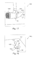
- FIG. 15 to FIG. 18 Illustrate such an embodiment FIG. 15 to FIG. 18 , which are described in more detail below. These show spatial views while performing a method according to an exemplary embodiment of the invention for inserting the insulation holder 1300 into an insulation plate 902 using a hammer 1502.
- FIG. 15 shows how a hammer head 1502 is clamped between the clamping wings 1304, 1306 of the insulating material holder 1300.
- FIG. 16 shows how by means of the hammer head 1502 of the insulation holder 1300 is inserted into the insulation plate 902 so far that the stop plate 114 is seated on the insulation plate 902.
- FIG. 17 shows, as by means of the hammer head 1502, the insertion of the insulation holder 1300 in the insulation plate 902 starting from the state according to FIG. 16 will continue. In this case, the insulation holder 1300 is further inserted into the insulation plate 902 until the connection plate 1302 is seated on the stop plate 114 and thus almost on the insulation plate 902.
Landscapes
- Engineering & Computer Science (AREA)
- Architecture (AREA)
- Physics & Mathematics (AREA)
- Electromagnetism (AREA)
- Civil Engineering (AREA)
- Structural Engineering (AREA)
- Building Environments (AREA)
- Insulating Bodies (AREA)
- Installation Of Indoor Wiring (AREA)
Applications Claiming Priority (1)
| Application Number | Priority Date | Filing Date | Title |
|---|---|---|---|
| DE102011077657A DE102011077657A1 (de) | 2011-06-16 | 2011-06-16 | Dämmstoffhalter |
Publications (3)
| Publication Number | Publication Date |
|---|---|
| EP2535472A2 true EP2535472A2 (fr) | 2012-12-19 |
| EP2535472A3 EP2535472A3 (fr) | 2013-10-23 |
| EP2535472B1 EP2535472B1 (fr) | 2017-05-10 |
Family
ID=46319588
Family Applications (1)
| Application Number | Title | Priority Date | Filing Date |
|---|---|---|---|
| EP12171942.1A Not-in-force EP2535472B1 (fr) | 2011-06-16 | 2012-06-14 | Support pour matière isolante |
Country Status (2)
| Country | Link |
|---|---|
| EP (1) | EP2535472B1 (fr) |
| DE (1) | DE102011077657A1 (fr) |
Families Citing this family (1)
| Publication number | Priority date | Publication date | Assignee | Title |
|---|---|---|---|---|
| US9670662B2 (en) * | 2015-06-30 | 2017-06-06 | Timothy G. Newhoff | Marker with twisted reflective strip |
Citations (6)
| Publication number | Priority date | Publication date | Assignee | Title |
|---|---|---|---|---|
| DE7018445U (de) | 1970-05-16 | 1970-10-08 | Koerner Manfred | Mehrschichten-betonplatte. |
| DE7239182U (de) | 1973-01-18 | Michel R | Abstandhalterungs- und Verbindungsvorrichtung | |
| DE29705044U1 (de) | 1997-03-20 | 1997-07-03 | Rapp, Albert Bruno, 58802 Balve | Bauelement für Hochbauwerke |
| DE69516864T2 (de) | 1994-04-08 | 2000-10-19 | H.K. Composites, Inc. | Hochisolierende verbindungsstäbe und verfahren zu ihrer herstellung und ihrer anwendung in hochisolierten zusammengesetzten wänden |
| EP1449977A1 (fr) | 2003-02-18 | 2004-08-25 | Ruredil S.p.A. | Dispositif de ventilation d'un élément de construction en béton armé avec des cavites ou éléments à réduction de poids |
| DE10324760A1 (de) | 2003-05-26 | 2004-12-30 | Construction Systems Marketing Gmbh | Wandbauelement, Verfahren zur Herstellung eines Wandbauelements und ein Verbindungsmittel für ein Wandbauelement |
-
2011
- 2011-06-16 DE DE102011077657A patent/DE102011077657A1/de not_active Withdrawn
-
2012
- 2012-06-14 EP EP12171942.1A patent/EP2535472B1/fr not_active Not-in-force
Patent Citations (6)
| Publication number | Priority date | Publication date | Assignee | Title |
|---|---|---|---|---|
| DE7239182U (de) | 1973-01-18 | Michel R | Abstandhalterungs- und Verbindungsvorrichtung | |
| DE7018445U (de) | 1970-05-16 | 1970-10-08 | Koerner Manfred | Mehrschichten-betonplatte. |
| DE69516864T2 (de) | 1994-04-08 | 2000-10-19 | H.K. Composites, Inc. | Hochisolierende verbindungsstäbe und verfahren zu ihrer herstellung und ihrer anwendung in hochisolierten zusammengesetzten wänden |
| DE29705044U1 (de) | 1997-03-20 | 1997-07-03 | Rapp, Albert Bruno, 58802 Balve | Bauelement für Hochbauwerke |
| EP1449977A1 (fr) | 2003-02-18 | 2004-08-25 | Ruredil S.p.A. | Dispositif de ventilation d'un élément de construction en béton armé avec des cavites ou éléments à réduction de poids |
| DE10324760A1 (de) | 2003-05-26 | 2004-12-30 | Construction Systems Marketing Gmbh | Wandbauelement, Verfahren zur Herstellung eines Wandbauelements und ein Verbindungsmittel für ein Wandbauelement |
Also Published As
| Publication number | Publication date |
|---|---|
| DE102011077657A1 (de) | 2012-12-20 |
| EP2535472A3 (fr) | 2013-10-23 |
| EP2535472B1 (fr) | 2017-05-10 |
Similar Documents
| Publication | Publication Date | Title |
|---|---|---|
| EP3426857B1 (fr) | Élément de construction en béton armé | |
| EP2987595B1 (fr) | Agencement destiné à la fabrication de préfabriqués en béton doté d'au moins un rail d'ancrage intégré dans le préfabriqué en béton et procédé de fabrication de tels préfabriqués en béton | |
| EP2348162B1 (fr) | Procédé et dispositif d'étanchéification d'un joint de séparation et joint d'étanchéité à ancrage pour un joint de séparation | |
| EP3514297A1 (fr) | Rail profilé pourvu de bouchon destiné à la fixation sur un coffrage | |
| EP1857606A2 (fr) | Baguette destinée à l'installation sur l'extrémité inférieure d'une isolation thermique de bâtiments | |
| EP0918909A1 (fr) | Element de coffrage et construction d'un mur au moyen de tels elements de coffrage | |
| EP2535472B1 (fr) | Support pour matière isolante | |
| EP3990715B1 (fr) | Élément d'ancrage et procédé de montage d'un rail d'ancrage dans un élément de construction en béton | |
| EP1688551A1 (fr) | Elément de fixation pour rail de montage et ensemble de rails | |
| EP0952252B1 (fr) | Coffrage pour l'encastrement d'un rail | |
| EP3696338B1 (fr) | Unité de coffrage pourvue d'élément de liaison, ensemble de pièces destiné au montage d'un coffrage et coffrage permettant de former un élément en béton coulé | |
| EP2816168B1 (fr) | Pierre de coffrage destinée à la liaison avec un revêtement en béton | |
| EP1715130A2 (fr) | Élément de cadre, en particulier un chassis de sécurité | |
| DE102011017472A1 (de) | Befestigungsteil zum Eingießen in ein Betonelement | |
| EP1787002B1 (fr) | Ensemble d'elements comprenant au moins un meneau et au moins deux pieces d'extremite de meneau a integrer dans une vitre isolante | |
| DE102010029040A1 (de) | Montageschiene | |
| DE20020504U1 (de) | Schalungselement als verlorene Schalung und mit diesem versehenes Fertigteil | |
| DE102006002277B4 (de) | Befestigungsklammer | |
| DE20113441U1 (de) | Vorrichtung zur Halterung einer bleibenden Randschalung zum Schalen eines seitlichen Randes eines Betonteiles | |
| DE102024130545A1 (de) | Abdichtsystem an Durchbrechungen in Formwerkzeugen oder Schalungen für die Fertigung von mit textilen Gebilden verstärkten vorgespannten Betonbauteilen | |
| EP3339528A1 (fr) | Raccordement béton-bois et dispositif de fixation | |
| DE2216653A1 (de) | Einbau einer stahlzarge fuer eine tuer in eine mauerwerksoeffnung und eine solche tuer mit stahlzarge in einer mauerwerksoeffnung | |
| DE202012103496U1 (de) | Wärmedämmendes verlorenes Schalungselement | |
| DE102020112153A1 (de) | Eckprofil | |
| DE29907716U1 (de) | Schalungssystem |
Legal Events
| Date | Code | Title | Description |
|---|---|---|---|
| PUAI | Public reference made under article 153(3) epc to a published international application that has entered the european phase |
Free format text: ORIGINAL CODE: 0009012 |
|
| AK | Designated contracting states |
Kind code of ref document: A2 Designated state(s): AL AT BE BG CH CY CZ DE DK EE ES FI FR GB GR HR HU IE IS IT LI LT LU LV MC MK MT NL NO PL PT RO RS SE SI SK SM TR |
|
| AX | Request for extension of the european patent |
Extension state: BA ME |
|
| PUAL | Search report despatched |
Free format text: ORIGINAL CODE: 0009013 |
|
| AK | Designated contracting states |
Kind code of ref document: A3 Designated state(s): AL AT BE BG CH CY CZ DE DK EE ES FI FR GB GR HR HU IE IS IT LI LT LU LV MC MK MT NL NO PL PT RO RS SE SI SK SM TR |
|
| AX | Request for extension of the european patent |
Extension state: BA ME |
|
| RIC1 | Information provided on ipc code assigned before grant |
Ipc: E04B 1/76 20060101AFI20130918BHEP |
|
| 17P | Request for examination filed |
Effective date: 20140411 |
|
| RBV | Designated contracting states (corrected) |
Designated state(s): AL AT BE BG CH CY CZ DE DK EE ES FI FR GB GR HR HU IE IS IT LI LT LU LV MC MK MT NL NO PL PT RO RS SE SI SK SM TR |
|
| 17Q | First examination report despatched |
Effective date: 20141111 |
|
| REG | Reference to a national code |
Ref country code: DE Ref legal event code: R079 Ref document number: 502012010284 Country of ref document: DE Free format text: PREVIOUS MAIN CLASS: E04B0001760000 Ipc: E04B0001260000 |
|
| GRAP | Despatch of communication of intention to grant a patent |
Free format text: ORIGINAL CODE: EPIDOSNIGR1 |
|
| RIC1 | Information provided on ipc code assigned before grant |
Ipc: E04B 1/26 20060101AFI20161110BHEP |
|
| INTG | Intention to grant announced |
Effective date: 20161201 |
|
| GRAS | Grant fee paid |
Free format text: ORIGINAL CODE: EPIDOSNIGR3 |
|
| GRAA | (expected) grant |
Free format text: ORIGINAL CODE: 0009210 |
|
| AK | Designated contracting states |
Kind code of ref document: B1 Designated state(s): AL AT BE BG CH CY CZ DE DK EE ES FI FR GB GR HR HU IE IS IT LI LT LU LV MC MK MT NL NO PL PT RO RS SE SI SK SM TR |
|
| RAP1 | Party data changed (applicant data changed or rights of an application transferred) |
Owner name: ADOLF WUERTH GMBH & CO. KG Owner name: WUERTH INTERNATIONAL AG |
|
| REG | Reference to a national code |
Ref country code: GB Ref legal event code: FG4D Free format text: NOT ENGLISH |
|
| REG | Reference to a national code |
Ref country code: AT Ref legal event code: REF Ref document number: 892475 Country of ref document: AT Kind code of ref document: T Effective date: 20170515 Ref country code: CH Ref legal event code: EP |
|
| REG | Reference to a national code |
Ref country code: IE Ref legal event code: FG4D Free format text: LANGUAGE OF EP DOCUMENT: GERMAN |
|
| REG | Reference to a national code |
Ref country code: DE Ref legal event code: R096 Ref document number: 502012010284 Country of ref document: DE |
|
| PGFP | Annual fee paid to national office [announced via postgrant information from national office to epo] |
Ref country code: CH Payment date: 20170516 Year of fee payment: 6 |
|
| REG | Reference to a national code |
Ref country code: NL Ref legal event code: MP Effective date: 20170510 |
|
| REG | Reference to a national code |
Ref country code: LT Ref legal event code: MG4D |
|
| PG25 | Lapsed in a contracting state [announced via postgrant information from national office to epo] |
Ref country code: NO Free format text: LAPSE BECAUSE OF FAILURE TO SUBMIT A TRANSLATION OF THE DESCRIPTION OR TO PAY THE FEE WITHIN THE PRESCRIBED TIME-LIMIT Effective date: 20170810 Ref country code: FI Free format text: LAPSE BECAUSE OF FAILURE TO SUBMIT A TRANSLATION OF THE DESCRIPTION OR TO PAY THE FEE WITHIN THE PRESCRIBED TIME-LIMIT Effective date: 20170510 Ref country code: HR Free format text: LAPSE BECAUSE OF FAILURE TO SUBMIT A TRANSLATION OF THE DESCRIPTION OR TO PAY THE FEE WITHIN THE PRESCRIBED TIME-LIMIT Effective date: 20170510 Ref country code: ES Free format text: LAPSE BECAUSE OF FAILURE TO SUBMIT A TRANSLATION OF THE DESCRIPTION OR TO PAY THE FEE WITHIN THE PRESCRIBED TIME-LIMIT Effective date: 20170510 Ref country code: GR Free format text: LAPSE BECAUSE OF FAILURE TO SUBMIT A TRANSLATION OF THE DESCRIPTION OR TO PAY THE FEE WITHIN THE PRESCRIBED TIME-LIMIT Effective date: 20170811 Ref country code: LT Free format text: LAPSE BECAUSE OF FAILURE TO SUBMIT A TRANSLATION OF THE DESCRIPTION OR TO PAY THE FEE WITHIN THE PRESCRIBED TIME-LIMIT Effective date: 20170510 |
|
| PG25 | Lapsed in a contracting state [announced via postgrant information from national office to epo] |
Ref country code: PL Free format text: LAPSE BECAUSE OF FAILURE TO SUBMIT A TRANSLATION OF THE DESCRIPTION OR TO PAY THE FEE WITHIN THE PRESCRIBED TIME-LIMIT Effective date: 20170510 Ref country code: SE Free format text: LAPSE BECAUSE OF FAILURE TO SUBMIT A TRANSLATION OF THE DESCRIPTION OR TO PAY THE FEE WITHIN THE PRESCRIBED TIME-LIMIT Effective date: 20170510 Ref country code: IS Free format text: LAPSE BECAUSE OF FAILURE TO SUBMIT A TRANSLATION OF THE DESCRIPTION OR TO PAY THE FEE WITHIN THE PRESCRIBED TIME-LIMIT Effective date: 20170910 Ref country code: RS Free format text: LAPSE BECAUSE OF FAILURE TO SUBMIT A TRANSLATION OF THE DESCRIPTION OR TO PAY THE FEE WITHIN THE PRESCRIBED TIME-LIMIT Effective date: 20170510 Ref country code: BG Free format text: LAPSE BECAUSE OF FAILURE TO SUBMIT A TRANSLATION OF THE DESCRIPTION OR TO PAY THE FEE WITHIN THE PRESCRIBED TIME-LIMIT Effective date: 20170810 Ref country code: NL Free format text: LAPSE BECAUSE OF FAILURE TO SUBMIT A TRANSLATION OF THE DESCRIPTION OR TO PAY THE FEE WITHIN THE PRESCRIBED TIME-LIMIT Effective date: 20170510 Ref country code: LV Free format text: LAPSE BECAUSE OF FAILURE TO SUBMIT A TRANSLATION OF THE DESCRIPTION OR TO PAY THE FEE WITHIN THE PRESCRIBED TIME-LIMIT Effective date: 20170510 |
|
| REG | Reference to a national code |
Ref country code: DE Ref legal event code: R119 Ref document number: 502012010284 Country of ref document: DE |
|
| PG25 | Lapsed in a contracting state [announced via postgrant information from national office to epo] |
Ref country code: EE Free format text: LAPSE BECAUSE OF FAILURE TO SUBMIT A TRANSLATION OF THE DESCRIPTION OR TO PAY THE FEE WITHIN THE PRESCRIBED TIME-LIMIT Effective date: 20170510 Ref country code: DK Free format text: LAPSE BECAUSE OF FAILURE TO SUBMIT A TRANSLATION OF THE DESCRIPTION OR TO PAY THE FEE WITHIN THE PRESCRIBED TIME-LIMIT Effective date: 20170510 Ref country code: CZ Free format text: LAPSE BECAUSE OF FAILURE TO SUBMIT A TRANSLATION OF THE DESCRIPTION OR TO PAY THE FEE WITHIN THE PRESCRIBED TIME-LIMIT Effective date: 20170510 Ref country code: SK Free format text: LAPSE BECAUSE OF FAILURE TO SUBMIT A TRANSLATION OF THE DESCRIPTION OR TO PAY THE FEE WITHIN THE PRESCRIBED TIME-LIMIT Effective date: 20170510 Ref country code: RO Free format text: LAPSE BECAUSE OF FAILURE TO SUBMIT A TRANSLATION OF THE DESCRIPTION OR TO PAY THE FEE WITHIN THE PRESCRIBED TIME-LIMIT Effective date: 20170510 |
|
| PG25 | Lapsed in a contracting state [announced via postgrant information from national office to epo] |
Ref country code: IT Free format text: LAPSE BECAUSE OF FAILURE TO SUBMIT A TRANSLATION OF THE DESCRIPTION OR TO PAY THE FEE WITHIN THE PRESCRIBED TIME-LIMIT Effective date: 20170510 Ref country code: SM Free format text: LAPSE BECAUSE OF FAILURE TO SUBMIT A TRANSLATION OF THE DESCRIPTION OR TO PAY THE FEE WITHIN THE PRESCRIBED TIME-LIMIT Effective date: 20170510 |
|
| PLBE | No opposition filed within time limit |
Free format text: ORIGINAL CODE: 0009261 |
|
| STAA | Information on the status of an ep patent application or granted ep patent |
Free format text: STATUS: NO OPPOSITION FILED WITHIN TIME LIMIT |
|
| REG | Reference to a national code |
Ref country code: IE Ref legal event code: MM4A |
|
| REG | Reference to a national code |
Ref country code: FR Ref legal event code: ST Effective date: 20180228 |
|
| 26N | No opposition filed |
Effective date: 20180213 |
|
| GBPC | Gb: european patent ceased through non-payment of renewal fee |
Effective date: 20170810 |
|
| PG25 | Lapsed in a contracting state [announced via postgrant information from national office to epo] |
Ref country code: DE Free format text: LAPSE BECAUSE OF NON-PAYMENT OF DUE FEES Effective date: 20180103 Ref country code: LU Free format text: LAPSE BECAUSE OF NON-PAYMENT OF DUE FEES Effective date: 20170614 Ref country code: IE Free format text: LAPSE BECAUSE OF NON-PAYMENT OF DUE FEES Effective date: 20170614 |
|
| PG25 | Lapsed in a contracting state [announced via postgrant information from national office to epo] |
Ref country code: SI Free format text: LAPSE BECAUSE OF FAILURE TO SUBMIT A TRANSLATION OF THE DESCRIPTION OR TO PAY THE FEE WITHIN THE PRESCRIBED TIME-LIMIT Effective date: 20170510 Ref country code: FR Free format text: LAPSE BECAUSE OF NON-PAYMENT OF DUE FEES Effective date: 20170710 |
|
| REG | Reference to a national code |
Ref country code: BE Ref legal event code: MM Effective date: 20170630 |
|
| PG25 | Lapsed in a contracting state [announced via postgrant information from national office to epo] |
Ref country code: GB Free format text: LAPSE BECAUSE OF NON-PAYMENT OF DUE FEES Effective date: 20170810 |
|
| REG | Reference to a national code |
Ref country code: AT Ref legal event code: MM01 Ref document number: 892475 Country of ref document: AT Kind code of ref document: T Effective date: 20170614 |
|
| PG25 | Lapsed in a contracting state [announced via postgrant information from national office to epo] |
Ref country code: BE Free format text: LAPSE BECAUSE OF NON-PAYMENT OF DUE FEES Effective date: 20170630 |
|
| PG25 | Lapsed in a contracting state [announced via postgrant information from national office to epo] |
Ref country code: MT Free format text: LAPSE BECAUSE OF FAILURE TO SUBMIT A TRANSLATION OF THE DESCRIPTION OR TO PAY THE FEE WITHIN THE PRESCRIBED TIME-LIMIT Effective date: 20170510 |
|
| PG25 | Lapsed in a contracting state [announced via postgrant information from national office to epo] |
Ref country code: AT Free format text: LAPSE BECAUSE OF NON-PAYMENT OF DUE FEES Effective date: 20170614 |
|
| REG | Reference to a national code |
Ref country code: CH Ref legal event code: PL |
|
| PG25 | Lapsed in a contracting state [announced via postgrant information from national office to epo] |
Ref country code: LI Free format text: LAPSE BECAUSE OF NON-PAYMENT OF DUE FEES Effective date: 20180630 Ref country code: CH Free format text: LAPSE BECAUSE OF NON-PAYMENT OF DUE FEES Effective date: 20180630 |
|
| PG25 | Lapsed in a contracting state [announced via postgrant information from national office to epo] |
Ref country code: HU Free format text: LAPSE BECAUSE OF FAILURE TO SUBMIT A TRANSLATION OF THE DESCRIPTION OR TO PAY THE FEE WITHIN THE PRESCRIBED TIME-LIMIT; INVALID AB INITIO Effective date: 20120614 Ref country code: MC Free format text: LAPSE BECAUSE OF FAILURE TO SUBMIT A TRANSLATION OF THE DESCRIPTION OR TO PAY THE FEE WITHIN THE PRESCRIBED TIME-LIMIT Effective date: 20170510 |
|
| PG25 | Lapsed in a contracting state [announced via postgrant information from national office to epo] |
Ref country code: CY Free format text: LAPSE BECAUSE OF NON-PAYMENT OF DUE FEES Effective date: 20170510 |
|
| PG25 | Lapsed in a contracting state [announced via postgrant information from national office to epo] |
Ref country code: MK Free format text: LAPSE BECAUSE OF FAILURE TO SUBMIT A TRANSLATION OF THE DESCRIPTION OR TO PAY THE FEE WITHIN THE PRESCRIBED TIME-LIMIT Effective date: 20170510 |
|
| PG25 | Lapsed in a contracting state [announced via postgrant information from national office to epo] |
Ref country code: TR Free format text: LAPSE BECAUSE OF FAILURE TO SUBMIT A TRANSLATION OF THE DESCRIPTION OR TO PAY THE FEE WITHIN THE PRESCRIBED TIME-LIMIT Effective date: 20170510 |
|
| PG25 | Lapsed in a contracting state [announced via postgrant information from national office to epo] |
Ref country code: PT Free format text: LAPSE BECAUSE OF FAILURE TO SUBMIT A TRANSLATION OF THE DESCRIPTION OR TO PAY THE FEE WITHIN THE PRESCRIBED TIME-LIMIT Effective date: 20170510 |
|
| PG25 | Lapsed in a contracting state [announced via postgrant information from national office to epo] |
Ref country code: AL Free format text: LAPSE BECAUSE OF FAILURE TO SUBMIT A TRANSLATION OF THE DESCRIPTION OR TO PAY THE FEE WITHIN THE PRESCRIBED TIME-LIMIT Effective date: 20170510 |