EP2535533A2 - Centrale électrique à cycle combiné asymétrique - Google Patents
Centrale électrique à cycle combiné asymétrique Download PDFInfo
- Publication number
- EP2535533A2 EP2535533A2 EP12171698A EP12171698A EP2535533A2 EP 2535533 A2 EP2535533 A2 EP 2535533A2 EP 12171698 A EP12171698 A EP 12171698A EP 12171698 A EP12171698 A EP 12171698A EP 2535533 A2 EP2535533 A2 EP 2535533A2
- Authority
- EP
- European Patent Office
- Prior art keywords
- steam
- engine
- gas turbine
- power plant
- heat recovery
- Prior art date
- Legal status (The legal status is an assumption and is not a legal conclusion. Google has not performed a legal analysis and makes no representation as to the accuracy of the status listed.)
- Withdrawn
Links
- 238000011084 recovery Methods 0.000 claims abstract description 29
- XLYOFNOQVPJJNP-UHFFFAOYSA-N water Substances O XLYOFNOQVPJJNP-UHFFFAOYSA-N 0.000 claims abstract description 9
- 239000012530 fluid Substances 0.000 claims description 6
- 238000004891 communication Methods 0.000 claims description 4
- 230000001419 dependent effect Effects 0.000 claims 1
- 239000007789 gas Substances 0.000 description 145
- 238000000034 method Methods 0.000 description 8
- 239000002699 waste material Substances 0.000 description 8
- 238000010586 diagram Methods 0.000 description 4
- VNWKTOKETHGBQD-UHFFFAOYSA-N methane Chemical compound C VNWKTOKETHGBQD-UHFFFAOYSA-N 0.000 description 4
- 230000006835 compression Effects 0.000 description 2
- 238000007906 compression Methods 0.000 description 2
- 239000000446 fuel Substances 0.000 description 2
- 239000003345 natural gas Substances 0.000 description 2
- 230000001052 transient effect Effects 0.000 description 2
- 239000002918 waste heat Substances 0.000 description 2
- 239000000463 material Substances 0.000 description 1
- 230000007704 transition Effects 0.000 description 1
- 238000011144 upstream manufacturing Methods 0.000 description 1
Images

Classifications
-
- F—MECHANICAL ENGINEERING; LIGHTING; HEATING; WEAPONS; BLASTING
- F01—MACHINES OR ENGINES IN GENERAL; ENGINE PLANTS IN GENERAL; STEAM ENGINES
- F01K—STEAM ENGINE PLANTS; STEAM ACCUMULATORS; ENGINE PLANTS NOT OTHERWISE PROVIDED FOR; ENGINES USING SPECIAL WORKING FLUIDS OR CYCLES
- F01K23/00—Plants characterised by more than one engine delivering power external to the plant, the engines being driven by different fluids
- F01K23/02—Plants characterised by more than one engine delivering power external to the plant, the engines being driven by different fluids the engine cycles being thermally coupled
- F01K23/06—Plants characterised by more than one engine delivering power external to the plant, the engines being driven by different fluids the engine cycles being thermally coupled combustion heat from one cycle heating the fluid in another cycle
- F01K23/065—Plants characterised by more than one engine delivering power external to the plant, the engines being driven by different fluids the engine cycles being thermally coupled combustion heat from one cycle heating the fluid in another cycle the combustion taking place in an internal combustion piston engine, e.g. a diesel engine
-
- F—MECHANICAL ENGINEERING; LIGHTING; HEATING; WEAPONS; BLASTING
- F01—MACHINES OR ENGINES IN GENERAL; ENGINE PLANTS IN GENERAL; STEAM ENGINES
- F01K—STEAM ENGINE PLANTS; STEAM ACCUMULATORS; ENGINE PLANTS NOT OTHERWISE PROVIDED FOR; ENGINES USING SPECIAL WORKING FLUIDS OR CYCLES
- F01K23/00—Plants characterised by more than one engine delivering power external to the plant, the engines being driven by different fluids
- F01K23/02—Plants characterised by more than one engine delivering power external to the plant, the engines being driven by different fluids the engine cycles being thermally coupled
- F01K23/06—Plants characterised by more than one engine delivering power external to the plant, the engines being driven by different fluids the engine cycles being thermally coupled combustion heat from one cycle heating the fluid in another cycle
- F01K23/10—Plants characterised by more than one engine delivering power external to the plant, the engines being driven by different fluids the engine cycles being thermally coupled combustion heat from one cycle heating the fluid in another cycle with exhaust fluid of one cycle heating the fluid in another cycle
- F01K23/101—Regulating means specially adapted therefor
-
- Y—GENERAL TAGGING OF NEW TECHNOLOGICAL DEVELOPMENTS; GENERAL TAGGING OF CROSS-SECTIONAL TECHNOLOGIES SPANNING OVER SEVERAL SECTIONS OF THE IPC; TECHNICAL SUBJECTS COVERED BY FORMER USPC CROSS-REFERENCE ART COLLECTIONS [XRACs] AND DIGESTS
- Y02—TECHNOLOGIES OR APPLICATIONS FOR MITIGATION OR ADAPTATION AGAINST CLIMATE CHANGE
- Y02E—REDUCTION OF GREENHOUSE GAS [GHG] EMISSIONS, RELATED TO ENERGY GENERATION, TRANSMISSION OR DISTRIBUTION
- Y02E20/00—Combustion technologies with mitigation potential
- Y02E20/16—Combined cycle power plant [CCPP], or combined cycle gas turbine [CCGT]
Definitions
- the present disclosure generally relates to a combined cycle power plant, and more particularly relates to a combined cycle power plant having two different gas turbines.
- a combined cycle power plant utilizes a gas turbine and a steam turbine in combination to produce power.
- the power plant is arranged such that the gas turbine is thermally connected to the steam turbine through a heat recovery steam generator ("HRSG").
- HRSG heat recovery steam generator
- the HRSG employs heat from the exhaust gases of the gas turbine to create steam for expansion in the steam turbine.
- the primary efficiency of the combined cycle arrangement is the utilization of the otherwise wasted heat from the gas turbine exhaust gases.
- Some combined cycle power plants employ a number of gas turbines. Each gas turbine may be thermally coupled to the same HRSG, or each gas turbine may be thermally coupled to a different HRSG. Such a combined cycle power plant may not make the most efficient transfer of waste energy to the steam turbine. Thus, there is a desire for a combined cycle power plant that provides increased efficiency.
- the present invention resides in a combined cycle power plant including a first engine, a second engine, a first heat recovery steam generator, a second heat recovery steam generator, and a steam turbine.
- the second engine is relatively more productive but less efficient than the first engine.
- the first engine generates a first exhaust gas
- the second engine generates a second exhaust gas.
- the first heat recovery steam generator transfers excess energy from the first exhaust gas to a first flow of water, creating a first flow of steam.
- the second heat recovery steam generator transfers excess energy from the second exhaust gas to a second flow of water, creating a second flow of steam.
- the second heat recovery steam generator further transfers excess energy from the second exhaust gas to the first flow of steam and the second flow of steam, creating a flow of superheated steam.
- the steam turbine receives the flow of superheated steam from the second heat recovery steam generator.
- the two topping cycle engines are different from each other in a manner that causes one of the topping cycle engines to be more productive but less efficient than the other topping cycle engine.
- the two topping cycle engines are thermodynamically coupled to the bottoming cycle engine by way of a heat recovery system.
- the heat recovery system relies more heavily on the less efficient topping cycle engine to feed the bottoming cycle engine, thereby increasing the efficiency of the overall power plant.
- topping cycle engine generally refers to an engine within the combined cycle power plant that generates waste energy that is recaptured for use in another portion of the combined cycle power plant.
- bottoming cycle engine generally refers to an engine within the combined cycle power plant that employs waste energy from a topping cycle engine, increasing the efficiency of the combined cycle power plant as a whole.
- the combined cycle power plant is "asymmetrical" because the topping cycle engines differ from each other.
- One of the topping cycle engines is more productive but less efficient than the other topping cycle engine due to at least one difference between the engines.
- the more productive topping cycle engine may be different from the more efficient topping cycle engine in terms of pressure ratio, size, power output, efficiency, exhaust gas temperature, or combinations thereof.
- the term "productive" with reference to an engine generally refers to the ability of the engine to generate useful shaft work, and in some cases the productivity of the engine may be represented by the maximum temperature and pressure ratio of the engine for a particular cycle.
- the more productive topping cycle engine is an industrial heavy-duty gas turbine
- the more efficient topping cycle engine is an aeroderivative gas turbine or a reciprocating engine, such as a natural gas fired Diesel engine.
- the bottoming cycle engine is generally a steam turbine.
- the principles of the present disclosure can be employed with reference to asymmetrical combined cycle power plants that have other numbers or combinations of engines.
- FIG. 1 is a schematic diagram of embodiment of an asymmetrical combined cycle power plant 100.
- the power plant 100 includes first and second topping cycle engines 102, 104 and one bottoming cycle engine 110.
- the first topping cycle engine 102 is an aeroderivative gas turbine 106
- the second topping cycle engine 104 is an industrial gas turbine 108, although other engines can be used.
- the industrial gas turbine 108 may be a large and robust machine that is fixed in place due to its size and is capable of generating a large output during steady state operation.
- the industrial gas turbine 108 may exhibit good tolerances for high temperatures and loads for extended periods, but may experience a long transition period on startup and may not be suited for absorbing rapid thermal changes associated with frequent startups and shutdowns.
- the aeroderivative gas turbine 106 may be a smaller and lighter machine that is suited for quick startup and shut down, but generates a smaller output once fully operational.
- the aeroderivative gas turbine 106 may be relatively fuel efficient in comparison to an industrial gas turbine 108, but may be less reliable.
- the industrial gas turbine 108 differs from the aeroderivative gas turbine 106 in pressure ratio, power output, efficiency, and exhaust gas temperature.
- the industrial gas turbine 108 may have a lower pressure ratio than the aeroderivative gas turbine 106 but may generate a higher temperature exhaust gas.
- the industrial gas turbine 108 may be an E- or F-Class turbine by General Electric Company, such as a Model 7EA gas turbine, which has an 85 MW output capacity, or a Model 7FA gas turbine, which has a 212 MW output capacity.
- the temperature of the exhaust gas from the industrial gas turbine 108 may be relatively high, such as about 1150°F or higher.
- the aeroderivative gas turbine 106 may be a Model LMS100 gas turbine, which also is made by General Electric Company.
- the LMS100 is dry-low emission (DLE) machine that has a 98 MW output capacity and is capable of achieving a full load within ten minutes from standstill.
- the temperature of the exhaust gas from the aeroderivative gas turbine 106 may be relatively lower, such as about 800°F or lower.
- topping cycle engines 102, 104 can be used in other embodiments of the combined cycle power plant 100.
- the aeroderivative gas turbine 106 can be substituted with a reciprocating engine, such as a natural gas fired Diesel engine.
- the bottoming cycle engine 110 is a steam turbine.
- the steam turbine may be a non-reheat steam turbine, such as a 1400 psig machine with an operating temperature of about 978°F or 1050°F. Such a steam turbine may have an output capacity of about 69 MW or about 117 MW.
- the steam turbine may be a reheat steam turbine, such as with steam pressures of 1800 psig or higher and steam temperatures of 1050°F or higher.
- Such a reheat steam turbine may achieve a better overall combined cycle efficiency in combination with larger industrial gas turbines, such as an F-Class gas turbine from General Electric Company.
- Other steam turbines may be employed based on, for example, desired cost and performance.
- the two topping cycle engines are thermodynamically coupled to the bottoming cycle engine by way of at least one heat recovery steam generator (HRSG).
- the HRSG recovers heat from exhaust gases exiting the topping cycle engine and employs the heat to create steam for expansion in the bottoming cycle engine.
- the HRSG may have one or more pressure sections, such as a high-pressure section, an intermediate pressure section, and a low-pressure section.
- Each pressure section may include any combination of evaporators, superheaters, and economizers.
- Each of these components typically includes a bundle of tubes across which the exhaust gases flow, transferring heat from the exhaust gases to the fluid flowing through the tubes.
- the evaporator has feedwater flowing through its tubes, and the exhaust gases cause the feedwater to turn to steam.
- the superheater has steam flowing through its tubes, and the exhaust gases heat the steam to create superheated steam.
- the economizer has feedwater flowing through its tubes, and the exhaust gases preheat the feedwater for use in the evaporator.
- One conventional configuration for an HRSG defines a flow path for the exhaust gases that extends horizontally through the HRSG, and the tubes of the various components extend vertically through the HRSG.
- the superheater is usually positioned upstream of the evaporator, and the economizer is usually positioned downstream of the evaporator, so that the exhaust gases flow over the superheater, the evaporator, and the economizer in succession.
- HRSG configurations can be employed.
- the combined cycle power plant 100 is arranged such that the exhaust gases of both the industrial gas turbine 108 and the aeroderivative gas turbine 106 are used to create steam, but the exhaust gases of the industrial gas turbine 108 are disproportionately used to superheat the steam.
- the industrial gas turbine 108 and the aeroderivative gas turbine 106 may each be associated with an HRSG. Both HRSGs may be used to create steam, but the HRSG of the industrial gas turbine 108 is disproportionately used to superheat the steam.
- the steam created by the HRSG associated with the aeroderivative gas turbine 106 may be routed to the HRSG associated with the industrial gas turbine 108 for superheating.
- the aeroderivative gas turbine 106 is associated with a first HRSG 112, and the industrial gas turbine 108 is associated with a second HRSG 114.
- the second HRSG 114 can be a two-pressure or three-pressure unit with reheat or no reheat.
- the first HRSG 112 may be a one or two-pressure unit with no reheat and with no superheater or a bypassed superheater.
- Such a configuration recognizes that the exhaust gas of the aeroderivative gas turbine 106 may not have enough energy for the reheat process or for superheating.
- the limited energy in the exhaust gas of the aeroderivative gas turbine 106 is preserved for steam generation, enabling steam generation at a higher pressure.
- the industrial gas turbine 108 is operated to generate a first output, also generating hot exhaust gases in the process.
- the aeroderivative gas turbine 106 is operated to generate a second output, also generating hot exhaust gases in the process.
- the hot exhaust gases from the aeroderivative gas turbine 106 are provided to the first HRSG 112, which recovers heat from the hot exhaust gases to produce a first flow of steam.
- the hot exhaust gases from the industrial gas turbine are provided to the second HRSG 114, which recovers heat from the hot exhaust gases to produce a second flow of steam.
- the first and second flows of steam are provided to the second HRSG 114, which creates a flow of superheated steam from the first and second flows of steam.
- the second HRSG 114 then provides the flow of superheated steam to the steam turbine for expansion therein.
- Such a configuration is effective because the exhaust gases of the industrial gas turbine 108 tend to have relatively more excess energy than the exhaust gases of the aeroderivative gas turbine 106.
- the exhaust gases of the aeroderivative gas turbine 106 may have enough energy to create a portion of the steam that is expanded in the steam turbine, while the exhaust gases of the industrial gas turbine 108 may have enough energy to create the remainder of the steam and to superheat all of the steam that is expanded in the steam turbine.
- the exhaust gases from the industrial gas turbine 108 may have a temperature of 1150°F and may be suited to generate high-pressure steam and to superheat the steam to 1050°F or higher, while exhaust gases from the aeroderivative gas turbine 106 may have a temperature of 800°F and may be suited to generate steam at 1800 psi or higher at a saturation temperature of 621 °F.
- the first HRSG 112 includes at least one evaporator 116 and at least one superheater 118
- the second HRSG 114 includes at least one evaporator 120 and at least one superheater 122.
- the evaporator 116 of the first HRSG 112 is in fluid communication with both of the superheaters 118, 122 by way of at least one steam delivery pipe 124 associated with at least one valve 126.
- the valve 126 may be controlled, such as via a controller, to deliver steam from the evaporator 116 to one or both of the superheaters 118, 122 at various points during the operational cycle.
- steam from the evaporator 116 may be directed to the superheater 118 of the first HRSG 112 during startup operations, during transient operations, when the industrial gas turbine is not operational, or when the industrial gas turbine is not fully operational. Otherwise, steam from the evaporator 116 may directed to the superheater 122 of the second HRSG 114, as hotter exhaust gases are flowing through the second HRSG 114 during steady state operation.
- the superheater 118 of the first HRSG 112 may be used at appropriate times during the operational cycle but otherwise may be bypassed. Bypassing the superheater 118 effectively entails not directing steam through the superheater 118, such that the superheater 118 is dry. Because the exhaust gases flowing through the first HRSG 112 may have a relatively lower temperature, such as around 800°F or so, dry operation may not impose a substantial hurdle in terms of superheater tube material selection.
- the industrial gas turbine 108 may experience a delay before it ramps up, but the aeroderivative gas turbine 106 may ramp up relatively quickly, creating exhaust gases that flow through the first HRSG 112.
- the exhaust gases may evaporate water flowing through the evaporator 116, creating steam that flows through the supply line 124.
- the valve 126 may be operated so that the steam flowing through supply line 124 is directed to the superheater 118 and not the superheater 122.
- the exhaust gases flowing through the first HRSG 112 may superheat the steam flowing through the superheater 118 to create superheated steam, which is provided to the steam turbine for expansion therein.
- the aeroderivative gas turbine 106 may generate exhaust gases that flow through the first HRSG 112, and the industrial gas turbine 108 may generate exhaust gases that flow through the second HRSG 114.
- the exhaust gases flowing through the first HRSG 112 may evaporate water flowing through the evaporator 116, creating steam that flows through the supply line 124.
- the valve 126 may be operated so that the steam flowing through supply line 124 is directed to the superheater 122, by passing the superheater 118.
- the exhaust gases flowing through the second HRSG 114 may superheat the steam flowing through the superheater 122 to create superheated steam, which is provided to the steam turbine for expansion therein.
- the exhaust gases flowing through the second HRSG 114 also may evaporate water flowing through the evaporator 120, creating steam that is superheated in the superheater 122.
- the superheater 122 of the second HRSG 114 may be used to superheat all of the steam that is provided to the steam turbine during steady-state operations, while the superheater 118 of the first HRSG 112 may be used during startup or transient operations or when the industrial gas turbine is shutdown.
- the first HRSG 112 may lack a superheater completely, in which case the steam delivery pipe 122 may deliver steam exiting the evaporator 116 of the first HRSG 112 to the superheater 122 of the second HRSG 114.
- the superheater 122 of the second HRSG 114 may be used to superheat all of the steam that is provided to the steam turbine.
- the first HRSG 112 may be omitted completely, and the exhaust gases of the aeroderivative gas turbine 106 may be directed into the second HRSG 114 downstream of a high pressure section.
- the combined cycle power plant exhibits optimized thermal matching between the exhaust gas of the topping cycle (a heat source) and the working fluid of the bottoming cycle (a heat sink).
- the exhaust gas of the aeroderivative turbine is primarily used to produce steam at a pressure commensurate with its temperature, as the exhaust gas of the aeroderivative gas turbine has limited energy in comparison to the exhaust gas of the industrial gas turbine.
- the exhaust gas of the industrial gas turbine is used to both produce some of the steam and to superheat the majority of the steam, as the exhaust gases of the industrial gas turbine may have enough energy to superheat the steam to a temperature suited for use in the steam turbine.
- the exhaust gases of the aeroderivative gas turbine may produce a first portion of the steam
- the exhaust gases of the industrial gas turbine may produce a second portion of the steam
- the exhaust gases of the industrial gas turbine may superheat the first and second portions of the steam.
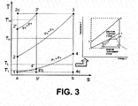
- FIG. 3 is a graph illustrating the relationship between temperature and entropy for the asymmetrical combined cycle power plant.
- the two topping cycle engines operate in accordance with the Brayton cycle.
- the points 1-2-3-4 represent the temperature-entropy behavior of the industrial gas turbine, which completes four distinct processes to generate work. First, isentropic compression occurs along line 1-2. Next, heat is added at constant pressure along line 2-3. Thereafter, isentropic compression occurs along line 3-4. Finally, heat is rejected at constant pressure along line 4-1.
- the area defined within points 1-2-3-4-1 represents the work produced by the industrial gas turbine, while the area defined between line 2-3 and the x-axis (points 1-2-3-4c-1) represents the heat added to the industrial gas turbine, and the area defined between line 4-1 and the x-axis (points 1-4-4c-1) represents the heat wasted by the industrial gas turbine.
- the difference between the heat added (points 1-2-3-4c-1) and the heat wasted (points 1-4-4c-1) represents the output of the industrial gas turbine.
- the area defined by the points 1-2'-3'-4'-1 represents the temperature-entropy behavior of the aeroderivative gas turbine.
- the two turbines exhibit comparable but different thermodynamic behavior for the same maximum cycle temperature.
- the aeroderivative gas turbine is more efficient than the industrial gas turbine, generating less waste energy as evidenced by the area defined by points 1-4'-4c'-1 in comparison to the area defined by points 1-4-4c-1, but the aeroderivative gas turbine also is less productive, as evidenced by the area within points 1-2'-3'-4'-1 in comparison to the area within points 1-2-3-4-1.
- One characteristic of an engine is its pressure ratio, which is represented by the vertical position of the line associated with the process of heat addition, such as 2-3 or 2'-3'.
- the aeroderivative gas turbine has a higher pressure ratio than the industrial gas turbine, as evidenced by the higher vertical position of the line 2'-3' in comparison to the line 2-3.
- the diagram reflects a relationship between pressure ratio, efficiency, output, and waste for the gas turbine: a gas turbine with a higher pressure ratio will exhibit higher efficiency and generate less waste but will also generate reduced output, while a gas turbine with a lower pressure ratio will exhibit lower efficiency and generate more waste but also will generate increased output.
- the asymmetrical combined cycle power plant described herein reflects a recognition that the wasted energy from the topping cycle constitutes an inefficiency only if it is not utilized in the bottoming cycle to generate additional output.
- the bottoming cycle draws disproportionately from the less efficient topping cycle engine (i.e. the engine with the lower pressure ratio) because the more efficient topping cycle engine (i.e. the engine with the higher pressure ratio) generates less waste heat that can perform work in the bottoming cycle.
- the maximum potential bottoming cycle work of the more efficient engine represented by the area within points 1-4'-4c'-1
- the maximum potential bottoming cycle work of the less efficient engine represented by the area defined within points 1-4-4c-1.
- FIG. 3 A graph illustrating the relationship between temperature and entropy for a steam turbine or other engine operating in accordance with the Rankine cycle is also illustrated in FIG. 3 .
- the graph for the steam turbine cycle is superimposed over the graph for the gas turbine cycle, schematically illustrating how the steam turbine of the bottoming cycle recaptures lost work from the topping cycle in the form of waste heat to generate additional work.
- the aeroderivative gas turbine enables bringing the asymmetrical combined cycle power plant online quickly and producing power quickly, while the industrial gas turbine enables generating a large output during steady state operation.
- an embodiment of the combined cycle power plant described above may achieve outputs of 115 or 140 MW in 10 minutes, about 185 or 310 MW in 20 minutes, and about 250 or 420 MW in 40 minutes.
- the total base load efficiency of the combined cycle power plant may be about 52% to 55%.
- the combined cycle power plant can be operated at a partial load by shutting down the aeroderivative gas turbine, without sacrificing the efficiency of the industrial gas turbine.
- the plant offers fast start-up and shut-down, efficient part load operations, and mixed fuel operations.
Landscapes
- Engineering & Computer Science (AREA)
- Chemical & Material Sciences (AREA)
- Combustion & Propulsion (AREA)
- Mechanical Engineering (AREA)
- General Engineering & Computer Science (AREA)
- Engine Equipment That Uses Special Cycles (AREA)
Applications Claiming Priority (1)
| Application Number | Priority Date | Filing Date | Title |
|---|---|---|---|
| US13/159,546 US20120317973A1 (en) | 2011-06-14 | 2011-06-14 | Asymmetrical Combined Cycle Power Plant |
Publications (2)
| Publication Number | Publication Date |
|---|---|
| EP2535533A2 true EP2535533A2 (fr) | 2012-12-19 |
| EP2535533A3 EP2535533A3 (fr) | 2013-09-25 |
Family
ID=46245942
Family Applications (1)
| Application Number | Title | Priority Date | Filing Date |
|---|---|---|---|
| EP12171698.9A Withdrawn EP2535533A3 (fr) | 2011-06-14 | 2012-06-12 | Centrale électrique à cycle combiné asymétrique |
Country Status (3)
| Country | Link |
|---|---|
| US (1) | US20120317973A1 (fr) |
| EP (1) | EP2535533A3 (fr) |
| CN (1) | CN102828831A (fr) |
Families Citing this family (14)
| Publication number | Priority date | Publication date | Assignee | Title |
|---|---|---|---|---|
| ITMI20102463A1 (it) * | 2010-12-30 | 2012-07-01 | Stamicarbon | Metodo per l'avviamento e la gestione di un impianto termico a ciclo combinato per la produzione di energia e relativo impianto |
| US9163827B2 (en) * | 2012-11-01 | 2015-10-20 | General Electric Company | System and method for using boiler feedwater |
| US9556793B2 (en) * | 2013-03-06 | 2017-01-31 | Kalex Systems Llc | Bottoming cycle for aeroderivative turbine-based combined power systems and methods for using same |
| US9500103B2 (en) | 2013-08-22 | 2016-11-22 | General Electric Company | Duct fired combined cycle system |
| CN105337397B (zh) * | 2014-06-18 | 2019-03-29 | 通用电气公司 | 钻探系统及其供电方法 |
| US9828884B2 (en) * | 2016-02-25 | 2017-11-28 | General Electric Technology Gmbh | System and method for preheating a heat recovery steam generator |
| US10436057B2 (en) * | 2016-12-23 | 2019-10-08 | Bechtel Infrastructure and Power Corporation | Gas turbine combined cycle for high flexibility |
| CN111868354B (zh) * | 2017-11-09 | 2022-09-30 | 三菱动力美洲株式会社 | 联合循环发电设备的附加发电 |
| WO2019112604A1 (fr) | 2017-12-08 | 2019-06-13 | Mitsubishi Hitachi Power Systems Americas, Inc. | Centrales électriques mettant en œuvre une réponse au déséquilibre de charge non congruente |
| JP7190373B2 (ja) * | 2019-03-07 | 2022-12-15 | 三菱重工業株式会社 | ガスタービン排熱回収プラント |
| US11549464B2 (en) * | 2019-07-25 | 2023-01-10 | Raytheon Technologies Corporation | Hybrid gas turbine engine starting control |
| GB2613844B (en) * | 2021-12-16 | 2023-12-13 | Landmark Tech Limited | Power generation system |
| KR102599921B1 (ko) * | 2022-03-21 | 2023-11-07 | 두산에너빌리티 주식회사 | 연소기용 노즐, 연소기, 및 이를 포함하는 가스 터빈 |
| WO2026083357A1 (fr) * | 2024-10-18 | 2026-04-23 | ACWA POWER Company | Système intégré de partage d'eau et de vapeur de refroidisseur à passage unique pour blocs de puissance à cycle combiné de turbine à gaz à unités multiples |
Family Cites Families (9)
| Publication number | Priority date | Publication date | Assignee | Title |
|---|---|---|---|---|
| JP2669545B2 (ja) * | 1988-10-14 | 1997-10-29 | 株式会社日立製作所 | 排熱回収ボイラシステムとその運転方法 |
| JPH06264763A (ja) * | 1993-03-11 | 1994-09-20 | Hitachi Ltd | コンバインドプラントシステム |
| US6237337B1 (en) * | 1998-09-10 | 2001-05-29 | Ormat Industries Ltd. | Retrofit equipment for reducing the consumption of fossil fuel by a power plant using solar insolation |
| US6608395B1 (en) * | 2000-03-28 | 2003-08-19 | Kinder Morgan, Inc. | Hybrid combined cycle power generation facility |
| US6430915B1 (en) * | 2000-08-31 | 2002-08-13 | Siemens Westinghouse Power Corporation | Flow balanced gas turbine power plant |
| US6442941B1 (en) * | 2000-09-11 | 2002-09-03 | General Electric Company | Compressor discharge bleed air circuit in gas turbine plants and related method |
| US20070130952A1 (en) * | 2005-12-08 | 2007-06-14 | Siemens Power Generation, Inc. | Exhaust heat augmentation in a combined cycle power plant |
| US20100180567A1 (en) * | 2009-01-16 | 2010-07-22 | General Electric Company | Combined Power Augmentation System and Method |
| JP5592752B2 (ja) * | 2010-10-22 | 2014-09-17 | 川崎重工業株式会社 | 発電システム |
-
2011
- 2011-06-14 US US13/159,546 patent/US20120317973A1/en not_active Abandoned
-
2012
- 2012-06-12 EP EP12171698.9A patent/EP2535533A3/fr not_active Withdrawn
- 2012-06-14 CN CN201210197114.0A patent/CN102828831A/zh active Pending
Non-Patent Citations (1)
| Title |
|---|
| None |
Also Published As
| Publication number | Publication date |
|---|---|
| US20120317973A1 (en) | 2012-12-20 |
| CN102828831A (zh) | 2012-12-19 |
| EP2535533A3 (fr) | 2013-09-25 |
Similar Documents
| Publication | Publication Date | Title |
|---|---|---|
| EP2535533A2 (fr) | Centrale électrique à cycle combiné asymétrique | |
| US20100170218A1 (en) | Method for expanding compressor discharge bleed air | |
| US8281565B2 (en) | Reheat gas turbine | |
| US5564269A (en) | Steam injected gas turbine system with topping steam turbine | |
| US20110113786A1 (en) | Combined cycle power plant with integrated organic rankine cycle device | |
| US6499302B1 (en) | Method and apparatus for fuel gas heating in combined cycle power plants | |
| US9188028B2 (en) | Gas turbine system with reheat spray control | |
| CN104279058B (zh) | 联合循环发电设备以及操作联合循环发电设备的方法 | |
| US20100242429A1 (en) | Split flow regenerative power cycle | |
| CN101865000A (zh) | 联合电力增强系统和方法 | |
| US9003764B2 (en) | System and method for thermal control in a gas turbine engine | |
| US20150052906A1 (en) | Duct Fired Combined Cycle System | |
| JP6162002B2 (ja) | グリッド周波数制御のための電力増大システムおよび方法 | |
| Mohanty et al. | Performance analysis of a combined cycle gas turbine under varying operating conditions | |
| US9074491B2 (en) | Steam cycle system with thermoelectric generator | |
| KR101887971B1 (ko) | 복합 화력 발전 설비들의 저 부하 턴다운 | |
| US10287922B2 (en) | Steam turbine plant, combined cycle plant provided with same, and method of operating steam turbine plant | |
| US20140069078A1 (en) | Combined Cycle System with a Water Turbine | |
| Tarasova et al. | Optimization of the Thermodynamic Cycle of a Combined-Cycle Power Plant | |
| EP3318733B1 (fr) | Système de dérivation d'eau d'alimentation pour un désurchauffeur | |
| Khaliq et al. | Energetic and exergetic efficiency analysis of an indirect fired air-turbine combined heat and power system | |
| Tsatsaronis et al. | Energetic and exergetic analysis of complex systems | |
| Doligalski et al. | Assessing the Potential of Gas-Recuperation in Reheated Gas Turbines Within Combined Gas-Steam Power Plants | |
| JP2026025931A (ja) | 熱回収蒸気発生器を用いた単純サイクル動作用の蒸気タービンバイパスを伴う複合サイクル発電プラント、および使用方法 | |
| JP3086787B2 (ja) | 水素燃焼タービンプラントの過速防止装置 |
Legal Events
| Date | Code | Title | Description |
|---|---|---|---|
| PUAI | Public reference made under article 153(3) epc to a published international application that has entered the european phase |
Free format text: ORIGINAL CODE: 0009012 |
|
| AK | Designated contracting states |
Kind code of ref document: A2 Designated state(s): AL AT BE BG CH CY CZ DE DK EE ES FI FR GB GR HR HU IE IS IT LI LT LU LV MC MK MT NL NO PL PT RO RS SE SI SK SM TR |
|
| AX | Request for extension of the european patent |
Extension state: BA ME |
|
| PUAL | Search report despatched |
Free format text: ORIGINAL CODE: 0009013 |
|
| AK | Designated contracting states |
Kind code of ref document: A3 Designated state(s): AL AT BE BG CH CY CZ DE DK EE ES FI FR GB GR HR HU IE IS IT LI LT LU LV MC MK MT NL NO PL PT RO RS SE SI SK SM TR |
|
| AX | Request for extension of the european patent |
Extension state: BA ME |
|
| RIC1 | Information provided on ipc code assigned before grant |
Ipc: F01K 23/06 20060101ALI20130822BHEP Ipc: F01K 23/10 20060101AFI20130822BHEP |
|
| STAA | Information on the status of an ep patent application or granted ep patent |
Free format text: STATUS: THE APPLICATION IS DEEMED TO BE WITHDRAWN |
|
| 18D | Application deemed to be withdrawn |
Effective date: 20140326 |