EP2535535B1 - Statischer Mischer - Google Patents
Statischer Mischer Download PDFInfo
- Publication number
- EP2535535B1 EP2535535B1 EP12163743.3A EP12163743A EP2535535B1 EP 2535535 B1 EP2535535 B1 EP 2535535B1 EP 12163743 A EP12163743 A EP 12163743A EP 2535535 B1 EP2535535 B1 EP 2535535B1
- Authority
- EP
- European Patent Office
- Prior art keywords
- circumferential direction
- circumferential
- mixer according
- coupling
- adjacent
- Prior art date
- Legal status (The legal status is an assumption and is not a legal conclusion. Google has not performed a legal analysis and makes no representation as to the accuracy of the status listed.)
- Revoked
Links
Images


Classifications
-
- B—PERFORMING OPERATIONS; TRANSPORTING
- B01—PHYSICAL OR CHEMICAL PROCESSES OR APPARATUS IN GENERAL
- B01F—MIXING, e.g. DISSOLVING, EMULSIFYING OR DISPERSING
- B01F23/00—Mixing according to the phases to be mixed, e.g. dispersing or emulsifying
- B01F23/20—Mixing gases with liquids
- B01F23/21—Mixing gases with liquids by introducing liquids into gaseous media
- B01F23/213—Mixing gases with liquids by introducing liquids into gaseous media by spraying or atomising of the liquids
- B01F23/2132—Mixing gases with liquids by introducing liquids into gaseous media by spraying or atomising of the liquids using nozzles
-
- B—PERFORMING OPERATIONS; TRANSPORTING
- B01—PHYSICAL OR CHEMICAL PROCESSES OR APPARATUS IN GENERAL
- B01F—MIXING, e.g. DISSOLVING, EMULSIFYING OR DISPERSING
- B01F25/00—Flow mixers; Mixers for falling materials, e.g. solid particles
- B01F25/30—Injector mixers
- B01F25/31—Injector mixers in conduits or tubes through which the main component flows
- B01F25/313—Injector mixers in conduits or tubes through which the main component flows wherein additional components are introduced in the centre of the conduit
- B01F25/3131—Injector mixers in conduits or tubes through which the main component flows wherein additional components are introduced in the centre of the conduit with additional mixing means other than injector mixers, e.g. screens, baffles or rotating elements
-
- B—PERFORMING OPERATIONS; TRANSPORTING
- B01—PHYSICAL OR CHEMICAL PROCESSES OR APPARATUS IN GENERAL
- B01F—MIXING, e.g. DISSOLVING, EMULSIFYING OR DISPERSING
- B01F25/00—Flow mixers; Mixers for falling materials, e.g. solid particles
- B01F25/40—Static mixers
- B01F25/42—Static mixers in which the mixing is affected by moving the components jointly in changing directions, e.g. in tubes provided with baffles or obstructions
- B01F25/43—Mixing tubes, e.g. wherein the material is moved in a radial or partly reversed direction
- B01F25/431—Straight mixing tubes with baffles or obstructions that do not cause substantial pressure drop; Baffles therefor
- B01F25/4315—Straight mixing tubes with baffles or obstructions that do not cause substantial pressure drop; Baffles therefor the baffles being deformed flat pieces of material
-
- B—PERFORMING OPERATIONS; TRANSPORTING
- B01—PHYSICAL OR CHEMICAL PROCESSES OR APPARATUS IN GENERAL
- B01F—MIXING, e.g. DISSOLVING, EMULSIFYING OR DISPERSING
- B01F25/00—Flow mixers; Mixers for falling materials, e.g. solid particles
- B01F25/40—Static mixers
- B01F25/42—Static mixers in which the mixing is affected by moving the components jointly in changing directions, e.g. in tubes provided with baffles or obstructions
- B01F25/43—Mixing tubes, e.g. wherein the material is moved in a radial or partly reversed direction
- B01F25/431—Straight mixing tubes with baffles or obstructions that do not cause substantial pressure drop; Baffles therefor
- B01F25/43197—Straight mixing tubes with baffles or obstructions that do not cause substantial pressure drop; Baffles therefor characterised by the mounting of the baffles or obstructions
- B01F25/431974—Support members, e.g. tubular collars, with projecting baffles fitted inside the mixing tube or adjacent to the inner wall
-
- F—MECHANICAL ENGINEERING; LIGHTING; HEATING; WEAPONS; BLASTING
- F01—MACHINES OR ENGINES IN GENERAL; ENGINE PLANTS IN GENERAL; STEAM ENGINES
- F01N—GAS-FLOW SILENCERS OR EXHAUST APPARATUS FOR MACHINES OR ENGINES IN GENERAL; GAS-FLOW SILENCERS OR EXHAUST APPARATUS FOR INTERNAL-COMBUSTION ENGINES
- F01N3/00—Exhaust or silencing apparatus having means for purifying, rendering innocuous, or otherwise treating exhaust
- F01N3/08—Exhaust or silencing apparatus having means for purifying, rendering innocuous, or otherwise treating exhaust for rendering innocuous
- F01N3/10—Exhaust or silencing apparatus having means for purifying, rendering innocuous, or otherwise treating exhaust for rendering innocuous by thermal or catalytic conversion of noxious components of exhaust
- F01N3/18—Exhaust or silencing apparatus having means for purifying, rendering innocuous, or otherwise treating exhaust for rendering innocuous by thermal or catalytic conversion of noxious components of exhaust characterised by methods of operation; Control
- F01N3/20—Exhaust or silencing apparatus having means for purifying, rendering innocuous, or otherwise treating exhaust for rendering innocuous by thermal or catalytic conversion of noxious components of exhaust characterised by methods of operation; Control specially adapted for catalytic conversion
- F01N3/206—Adding periodically or continuously substances to exhaust gases for promoting purification, e.g. catalytic material in liquid form, NOx reducing agents
- F01N3/2066—Selective catalytic reduction [SCR]
- F01N3/2073—Means for generating a reducing substance from the exhaust gases
-
- F—MECHANICAL ENGINEERING; LIGHTING; HEATING; WEAPONS; BLASTING
- F01—MACHINES OR ENGINES IN GENERAL; ENGINE PLANTS IN GENERAL; STEAM ENGINES
- F01N—GAS-FLOW SILENCERS OR EXHAUST APPARATUS FOR MACHINES OR ENGINES IN GENERAL; GAS-FLOW SILENCERS OR EXHAUST APPARATUS FOR INTERNAL-COMBUSTION ENGINES
- F01N3/00—Exhaust or silencing apparatus having means for purifying, rendering innocuous, or otherwise treating exhaust
- F01N3/08—Exhaust or silencing apparatus having means for purifying, rendering innocuous, or otherwise treating exhaust for rendering innocuous
- F01N3/10—Exhaust or silencing apparatus having means for purifying, rendering innocuous, or otherwise treating exhaust for rendering innocuous by thermal or catalytic conversion of noxious components of exhaust
- F01N3/24—Exhaust or silencing apparatus having means for purifying, rendering innocuous, or otherwise treating exhaust for rendering innocuous by thermal or catalytic conversion of noxious components of exhaust characterised by constructional aspects of converting apparatus
- F01N3/28—Construction of catalytic reactors
- F01N3/2892—Exhaust flow directors or the like, e.g. upstream of catalytic device
-
- F—MECHANICAL ENGINEERING; LIGHTING; HEATING; WEAPONS; BLASTING
- F01—MACHINES OR ENGINES IN GENERAL; ENGINE PLANTS IN GENERAL; STEAM ENGINES
- F01N—GAS-FLOW SILENCERS OR EXHAUST APPARATUS FOR MACHINES OR ENGINES IN GENERAL; GAS-FLOW SILENCERS OR EXHAUST APPARATUS FOR INTERNAL-COMBUSTION ENGINES
- F01N2240/00—Combination or association of two or more different exhaust treating devices, or of at least one such device with an auxiliary device, not covered by indexing codes F01N2230/00 or F01N2250/00, one of the devices being
- F01N2240/20—Combination or association of two or more different exhaust treating devices, or of at least one such device with an auxiliary device, not covered by indexing codes F01N2230/00 or F01N2250/00, one of the devices being a flow director or deflector
-
- Y—GENERAL TAGGING OF NEW TECHNOLOGICAL DEVELOPMENTS; GENERAL TAGGING OF CROSS-SECTIONAL TECHNOLOGIES SPANNING OVER SEVERAL SECTIONS OF THE IPC; TECHNICAL SUBJECTS COVERED BY FORMER USPC CROSS-REFERENCE ART COLLECTIONS [XRACs] AND DIGESTS
- Y02—TECHNOLOGIES OR APPLICATIONS FOR MITIGATION OR ADAPTATION AGAINST CLIMATE CHANGE
- Y02A—TECHNOLOGIES FOR ADAPTATION TO CLIMATE CHANGE
- Y02A50/00—TECHNOLOGIES FOR ADAPTATION TO CLIMATE CHANGE in human health protection, e.g. against extreme weather
- Y02A50/20—Air quality improvement or preservation, e.g. vehicle emission control or emission reduction by using catalytic converters
Definitions
- the present invention relates to a static mixer for installation in a fluid line, in particular for installation in an exhaust pipe of an internal combustion engine, having the features of the preamble of claim 1 and 2.
- the invention also relates to an exhaust system for an internal combustion engine, in particular a motor vehicle, with at least one such mixer is equipped, as in eg US 2685504 is shown.
- Modern exhaust systems of internal combustion engines may be equipped with an SCR system to reduce NOX emissions.
- an SCR system comprises a reducing agent supply device with the aid of which a suitable reducing agent, such as, for example, aqueous urea solution, can be introduced into an exhaust gas stream.
- a suitable reducing agent such as, for example, aqueous urea solution
- an SCR catalytic converter is arranged downstream of the reducing agent supply device, which reduces nitrogen oxides to water by means of ammonia.
- the reducing agent introduced in liquid form must be largely vaporized up to the SCR catalyst and mixed as homogeneously as possible with the exhaust gas stream.
- this mixing section which designates the distance from the reducing agent supply device to the SCR catalyst, can also be used to convert the introduced in aqueous solution of urea by hydrolysis reaction in ammonia and carbon dioxide.
- a thermolysis in which the urea is converted into ammonia and isocyanic acid.
- the actual hydrolysis takes place, in which the isocyanic acid is converted by means of water to ammonia and carbon dioxide.
- a static mixer which consists of a ring body having a row of blades with a plurality of ring body projecting inwardly from the guide vanes.
- the annular body is formed together with the guide vanes by a sheet metal part, which is made from a single sheet metal body by forming.
- a blank in the form of a flat sheet metal body is first cut several times to cut the vanes freely.
- the vanes are angled from the rest of the sheet metal body.
- the sheet metal body is bent with angled vanes about a transverse axis to its longitudinal axis until the peripheral ends abut. The production thus takes place in several steps, which is comparatively complicated, at least time-consuming.
- the present invention addresses the problem of providing for a static mixer of the type mentioned above, an improved or at least another embodiment, which is characterized in particular by an inexpensive manufacturability.
- This problem is solved according to the invention by the subject matters of the independent claims.
- Advantageous embodiments are the subject of the dependent claims.
- the invention is based on the general idea to assemble the annular body in the circumferential direction of at least two partial bodies, each partial body having a plurality of guide vanes. It has been found that the partial bodies with vanes made of blanks in the form of planar sheet metal bodies can be produced by a single forming process, in which within a single tool the guide vanes are cut free and angled, while at the same time the sheet metal body is bent about a bending axis extending transversely to its longitudinal direction, so as to produce in a single manufacturing step the respective partial body which corresponds to a circumferential segment of the annular body. With a ring body that extends over 360 ° closed, such a complex transformation can not be performed in a single operation.
- the ring body is assembled from two to four sub-bodies.
- an embodiment has been found in which the ring body is assembled from three sub-bodies.
- the circumferentially adjacent part body can engage in each other in the region of their circumferential ends and be pressed together.
- the adjacent body parts are positively connected with each other, without the need for elaborate cohesive connection measures, such as soldering and welding, must be performed.
- Possible attachment methods include, for example, clinching, clinching and crimping.
- the circumferentially adjacent sub-body can be arranged with their peripheral ends to shock.
- the circumferential ends of the circumferentially adjacent sub-bodies abut each other in the circumferential direction.
- the ring body also builds in the transition area flat between two adjacent sub-bodies.
- the annular body in the circumferential direction has a constant wall thickness.
- each partial body can have at least one coupling projection protruding in the circumferential direction at the one circumferential end and at least one coupling receptacle complementary thereto at the other peripheral end.
- the at least one coupling projection of the one partial body can now be brought into engagement with the at least one coupling receiver of the other partial body.
- the coupling projections and the coupling receptacles can be integrally formed on the part bodies, so that the provision of these coupling elements means no additional costs.
- coupling projection and coupling receptacle for forming a positive connection in particular for forming an undercut in the circumferential direction, be formed.
- the part body can be particularly easily set together.
- coupling protrusion and coupling receptacle such as the coupling elements of puzzle pieces may be configured to be, e.g. manually, easily engaged.
- the part body are identical parts.
- the annular body ultimately consists of two or more identical partial bodies, which are arranged adjacent to each other in the circumferential direction and connected to each other.
- the production costs for the individual parts can be reduced. If exactly two partial bodies are used for producing the annular body, each partial body extends over 180 ° in the circumferential direction. If exactly three partial bodies are used to produce the annular body, each partial body extends in the circumferential direction over 120 °. If there are four or more partial bodies, then corresponding peripheral sections result.
- the respective vane row is arranged on the annular body axially frontally.
- the respective row of vanes in which the vanes are adjacent in the circumferential direction, is located at the upstream end and at the downstream end, respectively, of the mixer and of the annular body.
- the annular body has a blade row on both axial end faces.
- the mixer has on the inflow and outflow side in each case a row of blades with circumferentially adjacent guide vanes. Due to the divided in the circumferential direction structure of the annular body thus also has the respective part body a plurality of upstream vanes and a plurality of downstream vanes.
- the vanes may have a position relative to the incoming exhaust flow such that they more or less deflect the incoming exhaust flow circumferentially.
- all the guide vanes have the same position relative to the exhaust gas flow, so that the flow through the blade row leads to a swirl in the exhaust gas flow.
- the flow direction of the exhaust gas corresponds to the axial direction of the mixer. If two rows of blades are now provided, the guide vanes of both blade rows can be set in the same direction with respect to the exhaust gas flow, so that the outflow-side blade row amplifies the swirl generated with the aid of the inflow side blade row. It is also possible to make the vanes of the two rows of blades in opposite directions with respect to the exhaust gas flow. As a result, the downstream side blade row reduces or eliminates the twist generated by the upstream side blade row. As a result, a particularly intensive mixing can be realized.
- the respective partial body can have at least one radial passage opening between the axial end faces of the annular body.
- a fixation of the body part within the forming tool can be particularly easily performed.
- this passage opening can also be used to fix the partial body in an exhaust pipe. For example, it is particularly easy to produce a weld in the area of the passage opening.
- the guide vanes in the respective row of blades may be arranged relative to one another without contact. This will Avoiding contact between blades of the same blade row, which avoids noise in the event of vibration.
- a plurality of guide vanes end radially inward on a circular core zone, while at least one guide blade protrudes into this core zone.
- the guide vanes can be attached to the respective part body.
- each part body is made integral with its vanes in one piece.
- each part of the body with its vanes is a sheet metal part, which is made of a single sheet metal body by forming.
- a method according to the invention for producing the mixer is characterized in that blanks which are formed by flat sheet metal pieces are each reshaped in a single forming tool into circular arc-shaped partial bodies with guide vanes projecting therefrom. The partial bodies are thereby end-formed and are tool-falling.
- An exhaust system according to the invention for an internal combustion engine, in particular of a motor vehicle comprises an exhaust pipe, in which at least one static mixer of the type described above is arranged. Upstream of this mixer the exhaust system can have a reducing agent supply device. Downstream of the mixer, the exhaust system may be equipped with an SCR catalyst.
- an internal combustion engine 1 comprises an engine block 2 with a plurality of combustion chambers 3 and an exhaust system 4 for discharging exhaust gases from the combustion chambers 3.
- the exhaust system 4 comprises an exhaust gas line 5, in which an SCR catalytic converter 6 is arranged. Upstream of the SCR catalytic converter 6, a reducing agent supply device 7 is connected to the exhaust gas line 5, with the aid of which a reducing agent 8, for example aqueous urea solution, can be introduced into the exhaust gas flow guided in the exhaust gas line 5. Between the Reduktionsffenzu slaughterhouse 7 and the SCR catalyst 6, a static mixer 9 is arranged in the exhaust pipe 5.
- the mixer 9 has according to the FIGS. 2 to 5 an annular body 10, which has at least one row of blades 11, wherein each row of blades 11 has a plurality of annular bodies 10 inwardly projecting vanes 12.
- the ring body 10 is composed of a plurality of sub-bodies 14 adjoining each other in the circumferential direction 13.
- the guide vanes 12 are formed integrally on the respective part body 14, so that the respective part body 14 together with its Guide vanes 12 is made of one piece. Particularly useful is the respective body part 14 together with its vanes 12, a sheet metal part, which is made from a single sheet metal body by forming.
- the partial bodies 14 can be configured such that they engage in one another in the region of their circumferential ends 15, 16 and are pressed together.
- the circumferential ends 15, 16 may be arranged in abutment, so that they rest against one another only in the circumferential direction 13 without radially overlapping or overlapping one another. In this way, a circumferentially continuous 13 wall thickness for the annular body 10 can be ensured.
- the respective partial body 14 has at the one circumferential end 15 a coupling projection 17 projecting in the circumferential direction 13 and at the other circumferential end 16 a coupling receiver 18 complementary to the coupling projection 17 FIG. 2 can be removed, are for connecting circumferentially 13 adjacent part bodies 14 of the coupling projection 17 of a partial body 14 and the coupling receptacle 18 of the other body part 14 with each other.
- coupling projection 17 and coupling receptacle 18 are expediently shaped in such a way that a form-fit connection can be produced. This is achieved in the example by an undercut with respect to the circumferential direction, the coupling projection 17 and in the coupling receptacle 18.
- the coupling projection 17 widens with increasing distance from the associated peripheral end 15.
- the coupling receptacle 18 tapers in the direction of the associated peripheral end 16.
- Coupling projection 17 and coupling receptacle 18 can be shaped in particular like the coupling elements of puzzle pieces and cooperate with one another.
- the individual part body 14 attached to each other, such that the coupling projections 17 engage in the associated coupling receptacles 18.
- a radial compression can be carried out, in which the coupling projections 17 in the circumferential direction 13 and axially, ie parallel to a in FIG.
- the partial bodies 14 are identical parts, so that in the present case three identical partial bodies 14 can be assembled to form the annular body 10.
- the ring body 10 has two blade rows 11, which are each arranged axially on the end face of the ring body 10.
- the assembly of the mixer 9 in the exhaust pipe 5 is carried out so that the longitudinal central axis 19 of the annular body 10 extends parallel to the main flow direction of the exhaust gas in the exhaust pipe 5.
- the annular body 10 is positioned coaxially with the respective exhaust gas line 5.
- the two blade rows 11 can also be referred to as the inflow-side blade row 11 'and outflow-side blade row 11 ".
- the individual body parts 14 are then expediently also equipped for each blade row 11 with a plurality of guide vanes 12.
- the guide vanes 12 have an angle of attack or a position relative to the inflow direction of the exhaust gas. Within the same blade row 11, the employment of the associated guide vanes 12 is the same. Thus, the flow through the blade row 11 can act on the exhaust gas flow with a twist. In the example shown here, the guide vanes 12 of both rows of blades 11 have in the same direction employment, whereby the downstream-side blade row 11 "amplifies the swirl of the inflow side blade row 11 '.
- the respective partial body 14 may have at least one radial passage opening 20 which is arranged between the axial end faces of the annular body 10.
- the passage opening 20 can be used, for example, during the production of the respective part body 14 for fixing the blank body serving as a blank in an associated forming tool. Furthermore, as part of the assembly of the mixer 9 in the exhaust pipe 5 in the region of this passage opening fixation of the respective body part 14 and thus of the entire annular body 10 on the exhaust pipe 5 done.
- the guide vanes 12 are arranged within the respective blade row 11 so that they do not touch each other. Furthermore, in FIG. 3 a circular core zone 21 recognizable. This core zone 21 is formed by the fact that within the respective blade row 11 a plurality of guide vanes 12 end radially inward at this core zone 21, such that the core zone 21 remains substantially free. In this way, in particular, it is achieved that the guide vanes 12 do not touch.
- the inflow-side blade row 11 ' has a plurality of guide vanes 12', which are longer than the other guide vanes 12 and accordingly protrude into the core zone 21.
- the freely flowable cross section can also be reduced in the region of the core zone 21. Because not all the vanes 12, but only a few vanes 12 'protrude into the core zone 21, can also ensure a non-contact positioning or a free-standing arrangement for these vanes 12'.
- the inflow-side blade row 11 ' has such longer guide blades 12', which protrude into the core zone 21.
- all guide vanes 12 are the same length and end at the core zone 21. Accordingly, the respective body part 14 has in each case at least one such longer guide blade 12 '.
- both blade rows 11 may be equipped with such longer guide blades 12 '. In another embodiment, it can also be provided that only the outflow-side blade row 11 "has such longer guide blades 12 '.
- the preparation of the mixer 9 is carried out such that from blanks, which are formed by planar sheet metal body, in a forming tool, in particular in a single forming process, the partial body 14 are endgeformt tool with the guide vanes 12. Subsequently, a plurality of body parts 14 are assembled to the ring body 10 and secured in the region of their peripheral ends 15, 16 to each other. For example, by radially compressing the abutting peripheral ends 15, 16 in the region of the intermeshing coupling projections 17 and coupling receivers 18. Subsequently, the annular body 10 and the mixer 9 is completed and can be installed in the exhaust pipe 5.
Landscapes
- Chemical & Material Sciences (AREA)
- Chemical Kinetics & Catalysis (AREA)
- Engineering & Computer Science (AREA)
- Health & Medical Sciences (AREA)
- Toxicology (AREA)
- Combustion & Propulsion (AREA)
- Mechanical Engineering (AREA)
- General Engineering & Computer Science (AREA)
- Dispersion Chemistry (AREA)
- Exhaust Gas After Treatment (AREA)
- Exhaust Gas Treatment By Means Of Catalyst (AREA)
- Exhaust Silencers (AREA)
Description
- Die vorliegende Erfindung betrifft einen statischen Mischer zum Einbau in eine Fluidleitung, insbesondere zum Einbau in eine Abgasleitung einer Brennkraftmaschine, mit den Merkmalen des Oberbegriffs des Anspruchs 1 bzw. 2. Die Erfindung betrifft außerdem eine Abgasanlage für eine Brennkraftmaschine, insbesondere eines Kraftfahrzeugs, die mit wenigstens einem derartigen Mischer ausgestattet ist, wie sie z.B. in
US 2685504 gezeigt ist. - Moderne Abgasanlagen von Brennkraftmaschinen können mit einer SCR-Anlage ausgestattet sein, um die NOX-Emissionen zu reduzieren. Eine derartige SCR-Anlage umfasst eine Reduktionsmittelzuführeinrichtung, mit deren Hilfe ein geeignetes Reduktionsmittel, wie zum Beispiel wässrige Harnstofflösung, in einen Abgasstrom eingebracht werden kann. Ferner ist stromab der Reduktionsmittelzuführeinrichtung ein SCR-Katalysator angeordnet, der Stickoxide mittels Ammoniak zu Wasser reduziert. Damit diese Reduktion im SCR-Katalysator ordnungsgemäß ablaufen kann, muss das in flüssiger Form eingebrachte Reduktionsmittel bis zum SCR-Katalysator weitgehend verdampft sein und möglichst homogen mit dem Abgasstrom vermischt sein. Insbesondere kann in dieser Mischstrecke, die den Abstand von der Reduktionsmittelzuführeinrichtung bis zum SCR-Katalysator bezeichnet, auch dazu genutzt werden, den in wässriger Lösung eingebrachten Harnstoff mittels Hydrolysereaktion in Ammoniak und Kohlendioxid umzuwandeln. Hierzu erfolgt zunächst eine Thermolyse, bei welcher der Harnstoff in Ammoniak und Isocyansäure umgewandelt wird. Anschließend erfolgt die eigentliche Hydrolyse, bei welcher die Isocyansäure mittels Wasser zu Ammoniak und Kohlendioxid umgewandelt wird.
- Um die Homogenisierung, die Verdampfung und gegebenenfalls die Hydrolyse zu verbessern, ist es bekannt, in besagter Mischstrecke zumindest einen statischen Mischer anzuordnen.
- Aus der
DE 2 006 017 A2 ist ein statischer Mischer bekannt, der aus einem Ringkörper besteht, der eine Schaufelreihe mit mehreren vom Ringkörper nach innen abstehenden Leitschaufeln aufweist. Beim bekannten Mischer ist der Ringkörper zusammen mit den Leitschaufeln durch ein Blechformteil gebildet, das aus einem einzigen Blechkörper durch Umformung hergestellt ist. Hierzu wird ein Rohling in Form eines ebenen Blechkörpers zunächst mehrfach eingeschnitten, um die Leitschaufeln frei zu schneiden. Anschließend werden die Leitschaufeln vom übrigen Blechkörper abgewinkelt. Danach wird der Blechkörper mit abgewinkelten Leitschaufeln um eine quer zu seiner Längsrichtung verlaufende Achse gebogen, bis sich die Umfangsenden stoßen. Die Herstellung erfolgt somit in mehreren Schritten, was vergleichsweise aufwändig, zumindest zeitintensiv ist. - Die vorliegende Erfindung beschäftigt sich mit dem Problem, für einen statischen Mischer der vorstehend genannten Art eine verbesserte oder zumindest eine andere Ausführungsform anzugeben, die sich insbesondere durch eine preiswerte Herstellbarkeit auszeichnet. Dieses Problem wird erfindungsgemäß durch die Gegenstände der unabhängigen Ansprüche gelöst. Vorteilhafte Ausführungsformen sind Gegenstand der abhängigen Ansprüche.
- Die Erfindung beruht auf dem allgemeinen Gedanken, den Ringkörper in der Umfangsrichtung aus wenigstens zwei Teilkörpern zusammenzubauen, wobei jeder Teilkörper mehrere Leitschaufeln aufweist. Es hat sich gezeigt, dass die Teilkörper mit Leitschaufeln aus Rohlingen in Form ebener Blechkörper durch einen einzigen Umformvorgang herstellbar sind, bei dem innerhalb eines einzigen Werkzeugs die Leitschaufeln freigeschnitten und abgewinkelt werden, während gleichzeitig auch der Blechkörper um eine quer zu seiner Längsrichtung verlaufende Biegeachse gebogen wird, um so in einem einzigen Fertigungsschritt den jeweiligen Teilkörper, der einem Umfangssegment des Ringkörpers entspricht, herzustellen. Mit einem Ringkörper, der sich über 360° geschlossen erstreckt, lässt sich eine derartige komplexe Umformung nicht in einem einzigen Arbeitsgang durchführen. Obwohl nun für die Herstellung des Mischers mehrere Einzelteile, nämlich die einzelnen Teilkörper hergestellt und aneinander befestigt werden müssen, hat sich überraschender Weise gezeigt, dass die Herstellung dieses mehrteiligen Mischers auf diese Weise insgesamt preiswerter ist als die bekannte Vorgehensweise, bei welcher der Ringkörper mit den Leitschaufeln aus einem einzigen Blechkörper hergestellt ist.
- Zweckmäßig ist der Ringkörper aus zwei bis vier Teilkörpern zusammengebaut. Besonders vorteilhaft hat sich eine Ausführungsform erwiesen, bei welcher der Ringkörper aus drei Teilkörpern zusammengebaut ist.
- Gemäß einer anderen Ausführungsform können die in Umfangsrichtung benachbarten Teilkörper im Bereich ihrer Umfangsenden ineinander eingreifen und miteinander verpresst sein. Hierdurch sind die benachbarten Teilkörper formschlüssig miteinander verbunden, ohne dass aufwändige stoffschlüssige Verbindungsmaßnahmen, wie zum Beispiel Löten und Schweißen, durchgeführt werden müssen. Mögliche Befestigungsmethoden sind beispielsweise Durchsetzfügen, Clinchen und Crimpen.
- Zweckmäßig können die in Umfangsrichtung benachbarten Teilkörper mit ihren Umfangsenden auf Stoß angeordnet sein. Mit anderen Worten, die Umfangsenden der in Umfangsrichtung benachbarten Teilkörper stoßen in der Umfangsrichtung aneinander an. Hierdurch baut der Ringkörper auch im Übergangsbereich zwischen zwei benachbarten Teilkörpern flach. Insbesondere hat der Ringkörper in der Umfangsrichtung eine gleichbleibende Wandstärke.
- Entsprechend einer besonders vorteilhaften Ausführungsform kann jeder Teilkörper an dem einen Umfangsende zumindest einen in Umfangsrichtung abstehenden Kopplungsvorsprung und am anderen Umfangsende zumindest eine dazu komplementäre Kopplungsaufnahme aufweisen. Zum Verbinden von in Umfangsrichtung benachbarten Teilkörpern kann nun der wenigstens eine Kopplungsvorsprung des einen Teilkörpers in die wenigstens eine Kopplungsaufnahme des anderen Teilkörpers in Eingriff gebracht werden. Die Kopplungsvorsprünge und die Kopplungsaufnahmen lassen sich integral an den Teilkörpern ausformen, so dass die Bereitstellung dieser Kopplungselemente keine zusätzlichen Kosten bedeutet.
- Gemäß einer vorteilhaften Weiterbildung können Kopplungsvorsprung und Kopplungsaufnahme zur Ausbildung einer Formschlussverbindung, insbesondere zur Ausbildung eines Hinterschnitts in Umfangsrichtung, geformt sein. Hierdurch lassen sich die Teilkörper besonders einfach aneinander festlegen. Beispielsweise können Kopplungsvorsprung und Kopplungsaufnahme wie die Kopplungselemente von Puzzleteilen ausgestaltet sein, so dass sie, z.B. manuell, einfach ineinander in Eingriff gebracht werden können.
- Besonders zweckmäßig ist eine Weiterbildung, bei welcher die stoßenden Umfangsenden im Bereich der ineinandergreifenden Kopplungsvorsprünge und Kopplungsaufnahme radial verpresst sind. Hierdurch lässt sich eine gezielte Deformation im Bereich der ineinandergreifenden Kopplungsvorsprünge erzeugen. Durch diese Verpressung bzw. Deformation werden die Kopplungsvorsprünge und die Kopplungsaufnahmen in der Umfangsrichtung und in der Axialrichtung bleibend miteinander verspannt, wodurch sich eine hinreichend feste Verbindung zwischen den benachbarten Teilkörpern einstellt.
- Besonders zweckmäßig ist eine Ausführungsform, bei welcher die Teilkörper Gleichteile sind. Somit besteht der Ringkörper letztlich aus zwei oder mehr gleichen Teilkörpern, die in Umfangsrichtung aneinander anschließend angeordnet und miteinander verbunden sind. Durch die Verwendung von Gleichteilen lassen sich die Herstellungskosten für die Einzelteile reduzieren. Sofern genau zwei Teilkörper zum Herstellen des Ringkörpers verwendet werden, erstreckt sich jeder Teilkörper über 180° in der Umfangsrichtung. Sofern genau drei Teilkörper zum Herstellen des Ringkörpers verwendet werden, erstreckt sich jeder Teilkörper in der Umfangsrichtung über 120°. Bei vier oder mehr Teilkörpern ergeben sich dann entsprechende Umfangsabschnitte.
- Besonders zweckmäßig ist eine Ausführungsform, bei welcher die jeweilige Leitschaufelreihe am Ringkörper axial stirnseitig angeordnet ist. Somit befindet sich die jeweilige Leitschaufelreihe, in welcher die Leitschaufeln in der Umfangsrichtung benachbart sind, am Anströmende bzw. am Abströmende des Mischers bzw. des Ringkörpers.
- Besonders vorteilhaft ist nun eine Weiterbildung, bei welcher der Ringkörper an beiden axialen Stirnseiten jeweils eine Schaufelreihe aufweist. Mit anderen Worten, der Mischer weist anströmseitig und abströmseitig jeweils eine Schaufelreihe mit in Umfangsrichtung benachbarten Leitschaufeln auf. Aufgrund der in der Umfangsrichtung geteilten Struktur des Ringkörpers weist somit auch der jeweilige Teilkörper mehrere anströmseitige Leitschaufeln und mehrere abströmseitige Leitschaufeln auf.
- Durch die Verwendung von zwei Schaufelreihen kann die Mischungswirkung des Mischers signifikant verbessert werden.
- Die Leitschaufeln können gegenüber der ankommenden Abgasströmung eine Anstellung aufweisen, so dass sie die ankommende Abgasströmung mehr oder weniger in Umfangsrichtung ablenken. Zweckmäßig besitzen innerhalb derselben Schaufelreihe alle Leitschaufeln die gleiche Anstellung gegenüber der Abgasströmung, so dass die Durchströmung der Schaufelreihe zu einem Drall in der Abgasströmung führt. Die Strömungsrichtung des Abgases entspricht dabei der Axialrichtung des Mischers. Sofern nun zwei Schaufelreihen vorgesehen sind, können die Leitschaufeln beider Schaufelreihen gleichsinnig gegenüber der Abgasströmung angestellt sein, so dass die abströmseitige Schaufelreihe den mit Hilfe der anströmseitigen Schaufelreihe erzeugten Drall verstärkt. Ebenso ist es möglich, die Leitschaufeln der beiden Schaufelreihen gegensinnig gegenüber der Abgasströmung anzustellen. In der Folge reduziert oder eliminiert die abströmseitige Schaufelreihe den mit Hilfe der anströmseitigen Schaufelreihe erzeugten Drall. Hierdurch lässt sich eine besonders intensive Durchmischung realisieren.
- Gemäß einer anderen Ausführungsform kann der jeweilige Teilkörper zwischen den axialen Stirnseiten des Ringkörpers zumindest eine radiale Durchgangsöffnung aufweisen. Mit Hilfe einer derartigen Durchgangsöffnung kann beispielsweise eine Fixierung des Teilkörpers innerhalb des Umformwerkzeugs besonders einfach durchgeführt werden. Ferner lässt sich diese Durchgangsöffnung auch dazu verwenden, den Teilkörper in einem Abgasrohr zu fixieren. Beispielsweise lässt sich im Bereich der Durchgangsöffnung besonders einfach eine Schweißnaht herstellen.
- Bei einer weiteren Ausführungsform können die Leitschaufeln in der jeweiligen Schaufelreihe relativ zueinander berührungslos angeordnet sein. Hierdurch wird ein Kontakt zwischen Schaufeln derselben Schaufelreihe vermieden, was eine Geräuschentwicklung im Falle von Vibrationen vermeidet.
- Besonders zweckmäßig können in der jeweiligen Schaufelreihe, vorzugsweise bei jedem Teilkörper, mehrere Leitschaufeln radial innen an einer kreisförmigen Kernzone enden, während zumindest eine Leitschaufel bis in diese Kernzone hineinragt. Durch diese Bauform lässt sich zum einen erreichen, dass die Schaufelreihe in der Axialrichtung nahezu blickdicht konfiguriert werden kann, so dass insbesondere ein Tröpfchendurchschlag vermieden werden kann. Dadurch, dass nicht alle Leitschaufeln in die Kernzone vorstehen, lässt sich auch eine Variante realisieren, bei welcher die Leitschaufeln einander nicht berühren.
- Grundsätzlich können die Leitschaufeln an den jeweiligen Teilkörper angebaut sein. Bevorzugt ist jedoch eine Ausführungsform, bei welcher jeder Teilkörper integral mit seinen Leitschaufeln aus einem Stück hergestellt ist.
- Eine besonders preiswerte Herstellbarkeit lässt sich dadurch erreichen, dass jeder Teilkörper mit seinen Leitschaufeln ein Blechformteil ist, das aus einem einzigen Blechkörper durch Umformung hergestellt ist.
- Ein erfindungsgemäßes Verfahren zum Herstellen des Mischers charakterisiert sich in diesem Fall dadurch, dass Rohlinge, die durch ebene Blechstücke gebildet sind, jeweils in einem einzigen Umformwerkzeug zu kreisbogenförmig gekrümmten Teilkörpern mit davon abstehenden Leitschaufeln umgeformt werden. Die Teilkörpern werden dabei endgeformt und sind werkzeugfallend.
- Eine erfindungsgemäße Abgasanlage für eine Brennkraftmaschine, insbesondere eines Kraftfahrzeugs, umfasst eine Abgasleitung, in der zumindest ein statischer Mischer der vorstehend beschriebenen Art angeordnet ist. Stromauf dieses Mischers kann die Abgasanlage eine Reduktionsmittelzuführeinrichtung aufweisen. Stromab des Mischers kann die Abgasanlage mit einem SCR-Katalysator ausgestattet sein.
- Weitere wichtige Merkmale und Vorteile der Erfindung ergeben sich aus den Unteransprüchen, aus den Zeichnungen und aus der zugehörigen Figurenbeschreibung anhand der Zeichnungen.
- Es versteht sich, dass die vorstehend genannten und die nachstehend noch zu erläuternden Merkmale nicht nur in der jeweils angegebenen Kombination, sondem auch in anderen Kombinationen oder in Alleinstellung verwendbar sind, ohne den Rahmen der vorliegenden Erfindung zu verlassen.
- Bevorzugte Ausführungsbeispiele der Erfindung sind in den Zeichnungen dargestellt und werden in der nachfolgenden Beschreibung näher erläutert, wobei sich gleiche Bezugszeichen auf gleiche oder ähnliche oder funktional gleiche Bauteile beziehen.
- Es zeigen, jeweils schematisch,
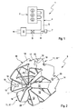
- Fig. 1
- eine stark vereinfachte, schaltplanartige Prinzipdarstellung einer Brennkraftmaschine,
- Fig. 2
- eine isometrische Ansicht eines Mischers,
- Fig. 3
- eine Axialansicht des Mischers,
- Fig. 4
- eine isometrische Ansicht eines Teilkörpers,
- Fig. 5
- eine andere isometrische Ansicht des Teilkörpers.
- Entsprechend
Figur 1 umfasst eine Brennkraftmaschine 1 einen Motorblock 2 mit mehreren Brennräumen 3 und eine Abgasanlage 4 zum Abführen von Abgasen von den Brennräumen 3. Die Abgasanlage 4 umfasst eine Abgasleitung 5, in der ein SCR-Katalysator 6 angeordnet ist. Stromauf des SCR-Katalysators 6 ist eine Reduktionsmittelzuführeinrichtung 7 an die Abgasleitung 5 angeschlossen, mit deren Hilfe ein Reduktionsmittel 8, zum Beispiel wässrige Harnstofflösung, in den in der Abgasleitung 5 geführten Abgasstrom einbringbar ist. Zwischen der Reduktionsmittelzuführeinrichtung 7 und dem SCR-Katalysator 6 ist ein statischer Mischer 9 in der Abgasleitung 5 angeordnet. - Der Mischer 9 besitzt gemäß den
Figuren 2 bis 5 einen Ringkörper 10, der zumindest eine Schaufelreihe 11 aufweist, wobei jede Schaufelreihe 11 mehrere vom Ringkörper 10 nach innen abstehende Leitschaufeln 12 aufweist. - Beim hier vorgestellten Mischer 9 besteht der Ringkörper 10 in der Umfangsrichtung, die in
Figur 3 durch einen Doppelpfeil angedeutet und mit 13 bezeichnet ist, aus zumindest zwei Teilkörpern 14, die jeweils mehrere Leitschaufeln 12 aufweisen. Ferner sind in der Umfangsrichtung 13 benachbarte Teilkörper 14 aneinander befestigt. Mit anderen Worten, der Ringkörper 10 ist aus mehreren Teilkörpem 14, die in der Umfangsrichtung 13 aneinander anschließen, zusammengebaut. - Beim hier gezeigten Beispiel sind genau drei derartige Teilkörper 14 vorgesehen, die sich jeweils über etwa 120° in der Umfangsrichtung 13 erstrecken.
- Gemäß den
Figuren 4 und 5 sind die Leitschaufeln 12 am jeweiligen Teilkörper 14 integral ausgeformt, so dass der jeweilige Teilkörper 14 zusammen mit seinen Leitschaufeln 12 aus einem Stück hergestellt ist. Besonders zweckmäßig ist dabei der jeweilige Teilkörper 14 zusammen mit seinen Leitschaufeln 12 ein Blechformteil, das aus einem einzigen Blechkörper durch Umformung hergestellt ist. - Zur Befestigung der in Umfangsrichtung 13 benachbarten Teilkörper 14 können die Teilkörper 14 so konfiguriert sein, dass sie im Bereich ihrer Umfangsenden 15, 16 ineinander eingreifen und miteinander verpresst sind. Hierzu können die Umfangsenden 15, 16 auf Stoß angeordnet sein, so dass sie also nur in der Umfangsrichtung 13 aneinander anliegen, ohne einander radial zu überlappen oder zu überdecken. Hierdurch kann eine in Umfangsrichtung 13 durchgehend konstante Wandstärke für den Ringkörper 10 gewährleistet werden.
- Bei der hier vorgestellten, besonders vorteilhaften Ausführungsform besitzt der jeweilige Teilkörper 14 an dem einen Umfangsende 15 einen in der Umfangsrichtung 13 abstehenden Kopplungsvorsprung 17 und am anderen Umfangsende 16 eine zum Kopplungsvorsprung 17 komplementäre Kopplungsaufnahme 18. Wie insbesondere
Figur 2 entnehmbar ist, stehen zum Verbinden von in Umfangsrichtung 13 benachbarten Teilkörpern 14 der Kopplungsvorsprung 17 des einen Teilkörpers 14 und die Kopplungsaufnahme 18 des anderen Teilkörpers 14 miteinander in Eingriff. Zweckmäßig sind dabei Kopplungsvorsprung 17 und Kopplungsaufnahme 18 so geformt, dass sich dabei eine Formschlussverbindung herstellen lässt. Erreicht wird dies im Beispiel durch einen Hinterschnitt bezüglich der Umfangsrichtung, am Kopplungsvorsprung 17 bzw. in der Kopplungsaufnahme 18. Beispielsweise weitet sich der Kopplungsvorsprung 17 mit zunehmendem Abstand vom zugehörigen Umfangsende 15 auf. Komplementär dazu verjüngt sich die Kopplungsaufnahme 18 in Richtung zum zugehörigen Umfangsende 16. Kopplungsvorsprung 17 und Kopplungsaufnahme 18 können dabei insbesondere wie die Kopplungselemente von Puzzleteilen geformt sein und miteinander zusammenwirken. Für die Montage des Ringkörpers 10 werden die einzelnen Teilkörper 14 aneinander angesetzt, derart, dass die Kopplungsvorsprünge 17 in die zugehörigen Kopplungsaufnahmen 18 eingreifen. Anschließend kann im Bereich der ineinander eingreifenden Kopplungsvorsprünge 17 und Kopplungsaufnahmen 18 eine radiale Verpressung durchgeführt werden, bei der die Kopplungsvorsprünge 17 in der Umfangsrichtung 13 und axial, also parallel zu einer inFigur 3 angedeuteten Längsmittelachse 19 des Mischers 9 bzw. des Ringkörpers 10, ausgedehnt und dabei plastisch verformt werden. Hierdurch erfolgt eine bleibende Verspannung der Kopplungsvorsprünge 17 in den Kopplungsaufnahmen 18. Die einzelnen Teilkörper 14 sind anschließend ausreichend fest miteinander verbunden, wodurch der Ringkörper 10 und somit der Mischer 9 einfach manipulierbar bzw. handhabbar ist, um ihn beispielsweise in der Abgasleitung 5 montieren zu können. - Zweckmäßig handelt es sich bei den Teilkörpern 14 um Gleichteile, so dass im vorliegenden Fall drei gleiche Teilkörper 14 zum Ringkörper 10 zusammengebaut werden können.
- Beim hier vorgestellten bevorzugten Beispiel besitzt der Ringkörper 10 zwei Schaufelreihen 11, die jeweils axial stirnseitig am Ringkörper 10 angeordnet sind. Die Montage des Mischers 9 in der Abgasleitung 5 erfolgt so, dass sich die Längsmittelachse 19 des Ringkörpers 10 parallel zur Hauptströmungsrichtung des Abgases in der Abgasleitung 5 erstreckt. Zweckmäßig ist dabei der Ringkörper 10 koaxial zur jeweiligen Abgasleitung 5 positioniert. Dementsprechend lassen sich die beiden Schaufelreihen 11 auch als anströmseitige Schaufelreihe 11' und abströmseitige Schaufelreihe 11" bezeichnen.
- Die einzelnen Teilkörper 14 sind dann zweckmäßig ebenfalls für jede Schaufelreihe 11 mit mehreren Leitschaufeln 12 ausgestattet.
- Die Leitschaufeln 12 besitzen gegenüber der Anströmrichtung des Abgases einen Anstellwinkel bzw. eine Anstellung. Innerhalb der gleichen Schaufelreihe 11 ist die Anstellung der zugehörigen Leitschaufeln 12 dabei gleich. Somit kann die Durchströmung der Schaufelreihe 11 die Abgasströmung mit einem Drall beaufschlagen. Im hier gezeigten Beispiel besitzen die Leitschaufeln 12 beider Schaufelreihen 11 gleichsinnige Anstellungen, wodurch die abströmseitige Schaufelreihe 11" den Drall der anströmseitigen Schaufelreihe 11' verstärkt.
- Wie sich den
Figuren 2 ,4 und 5 entnehmen lässt, kann der jeweilige Teilkörper 14 zumindest eine radiale Durchgangsöffnung 20 aufweisen, die zwischen den axialen Stirnseiten des Ringkörpers 10 angeordnet ist. Die Durchgangsöffnung 20 kann beispielsweise während der Herstellung des jeweiligen Teilkörpers 14 zur Fixierung des als Rohling dienenden Blechkörpers in einem zugehörigen Umformwerkzeug verwendet werden. Ferner kann im Rahmen der Montage des Mischers 9 in der Abgasleitung 5 im Bereich dieser Durchgangsöffnung eine Fixierung des jeweiligen Teilkörpers 14 und somit des gesamten Ringkörpers 10 an der Abgasleitung 5 erfolgen. - Wie sich insbesondere den
Figuren 2 bis 5 entnehmen lässt, sind die Leitschaufeln 12 innerhalb der jeweiligen Schaufelreihe 11 so angeordnet, dass sie einander nicht berühren. Ferner ist inFigur 3 eine kreisförmige Kernzone 21 erkennbar. Diese Kernzone 21 wird dadurch gebildet, dass innerhalb der jeweiligen Schaufelreihe 11 mehrere Leitschaufeln 12 radial innen an dieser Kernzone 21 enden, derart, dass die Kernzone 21 im Wesentlichen frei bleibt. Hierdurch wird insbesondere erreicht, dass sich die Leitschaufeln 12 nicht berühren. Im gezeigten Beispiel besitzt die anströmseitige Schaufelreihe 11' mehrere Leitschaufeln 12', die länger sind als die anderen Leitschaufeln 12 und dementsprechend bis in die Kernzone 21 hineinragen. Hierdurch kann auch im Bereich der Kernzone 21 der frei durchströmbare Querschnitt reduziert werden. Da nicht alle Leitschaufeln 12, sondern nur wenige Leitschaufeln 12' in die Kernzone 21 hineinragen, kann auch für diese Leitschaufeln 12' eine berührungslose Positionierung bzw. eine freistehende Anordnung gewährleisten werden. - Im gezeigten Beispiel besitzt nur die anströmseitige Schaufelreihe 11' derartige längere Leitschaufeln 12', die bis in die Kernzone 21 vorstehen. Bei der abströmseitigen Schaufelreihe 11" sind alle Leitschaufeln 12 gleich lang und enden an der Kernzone 21. Dementsprechend besitzt der jeweilige Teilkörper 14 jeweils wenigstens eine derartige längere Leitschaufel 12'.
- Bei einer anderen Ausführungsform können auch beide Schaufelreihen 11 mit derartigen längeren Leitschaufeln 12' ausgestattet sein. Bei einer anderen Ausführungsform kann auch vorgesehen sein, dass nur die abströmseitige Schaufelreihe 11" derartige längere Leitschaufeln 12' aufweist.
- Die Herstellung des Mischers 9 erfolgt derart, dass aus Rohlingen, die durch ebene Blechkörper gebildet sind, in einem Umformwerkzeug, insbesondere in einem einzigen Umformvorgang, die Teilkörper 14 mit den Leitschaufeln 12 werkzeugfallend endgeformt werden. Anschließend werden mehrere Teilkörper 14 zum Ringkörper 10 zusammengebaut und im Bereich ihrer Umfangsenden 15, 16 aneinander befestigt. Beispielsweise indem die stoßenden Umfangsenden 15, 16 im Bereich der ineinandergreifenden Kopplungsvorsprünge 17 und Kopplungsaufnahmen 18 radial verpresst werden. Anschließend ist der Ringkörper 10 bzw. der Mischer 9 fertiggestellt und kann in die Abgasleitung 5 eingebaut werden.
Claims (15)
- Statischer Mischer zum Einbau in eine Fluidleitung, insbesondere Abgasleitung (5) einer Brennkraftmaschine (1), mit einem Ringkörper (10), der mindestens eine Schaufelreihe (11) mit mehreren vom Ringkörper (10) nach innen abstehenden Leitschaufeln (12) aufweist,- wobei der Ringkörper (10) in der Umfangsrichtung (13) aus mindestens zwei Teilkörpern (14) besteht,- wobei in der Umfangsrichtung (13) benachbarte Teilkörper (14) aneinander befestigt sind,- wobei jeder Teilkörper (14) mehrere Leitschaufeln (12) aufweist,- wobei die in Umfangsrichtung (13) benachbarten Teilkörper (14) im Bereich ihrer Umfangsenden (15, 16) ineinander eingreifen,
dadurch gekennzeichnet,- dass die in Umfangsrichtung (13) benachbarten Teilkörper (14) im Bereich ihrer Umfangsenden (15, 16) miteinander verpresst sind,- dass die in Umfangsrichtung (13) benachbarten Teilkörper (14) mit ihren Umfangsenden (15, 16) in der Umfangsrichtung (13) auf Stoß angeordnet sind. - Statischer Mischer zum Einbau in eine Fluidleitung, insbesondere Abgasleitung (5) einer Brennkraftmaschine (1), mit einem Ringkörper (10), der mindestens eine Schaufelreihe (11) mit mehreren vom Ringkörper (10) nach innen abstehenden Leitschaufeln (12) aufweist,- wobei der Ringkörper (10) in der Umfangsrichtung (13) aus mindestens zwei Teilkörpern (14) besteht,- wobei in der Umfangsrichtung (13) benachbarte Teilkörper (14) aneinander befestigt sind,- wobei jeder Teilkörper (14) mehrere Leitschaufeln (12) aufweist,
dadurch gekennzeichnet,- dass die in Umfangsrichtung (13) benachbarten Teilkörper (14) mit ihren Umfangsenden (15, 16) in der Umfangsrichtung (13) auf Stoß angeordnet sind,- dass jeder Teilkörper (14) an dem einen Umfangsende (15) wenigstens einen in Umfangsrichtung (13) abstehenden Kopplungsvorsprung (17) und am anderen Umfangsende (16) wenigstens eine dazu komplementäre Kopplungsaufnahme (18) aufweist, wobei zum Verbinden von in Umfangsrichtung (13) benachbarten Teilkörpern (14) der wenigstens eine Kopplungsvorsprung (17) des einen Teilkörpers (14) mit der wenigstens eine Kopplungsaufnahme (18) des anderen Teilkörpers (14) in Eingriff steht,- dass Kopplungsvorsprung (17) und Kopplungsaufnahme (18) zur Ausbildung einer Formschlussverbindung in der Umfangsrichtung (13) geformt sind. - Mischer nach Anspruch 2,
dadurch gekennzeichnet,
dass die in Umfangsrichtung (13) benachbarten Teilkörper (14) im Bereich ihrer Umfangsenden (15, 16) ineinander eingreifen und miteinander verpresst sind. - Mischer nach Anspruch 2 oder 3,
dadurch gekennzeichnet,
dass Kopplungsvorsprung (17) und Kopplungsaufnahme (18) zur Ausbildung einer Formschlussverbindung in Form eines Hinterschnitts in der Umfangsrichtung (13) geformt sind. - Mischer nach Anspruch 1,
dadurch gekennzeichnet,
dass jeder Teilkörper (14) an dem einen Umfangsende (15) wenigstens einen in Umfangsrichtung (13) abstehenden Kopplungsvorsprung (17) und am anderen Umfangsende (16) wenigstens eine dazu komplementäre Kopplungsaufnahme (18) aufweist, wobei zum Verbinden von in Umfangsrichtung (13) benachbarten Teilkörpern (14) der wenigstens eine Kopplungsvorsprung (17) des einen Teilkörpers (14) mit der wenigstens eine Kopplungsaufnahme (18) des anderen Teilkörpers (14) in Eingriff steht. - Mischer nach Anspruch 5,
dadurch gekennzeichnet,
dass Kopplungsvorsprung (17) und Kopplungsaufnahme (18) zur Ausbildung einer Formschlussverbindung, insbesondere eines Hinterschnitts, in der Umfangsrichtung (13) geformt sind. - Mischer nach einem der Ansprüche 2 bis 6,
dadurch gekennzeichnet,
dass die stoßenden Umfangsenden (15, 16) im Bereich der ineinandergreifenden Kopplungsvorsprung (17) und Kopplungsaufnahme (18) radial verpresst sind. - Mischer nach einem der Ansprüche 1 bis 7,
dadurch gekennzeichnet,
dass die Teilkörper (14) Gleichteile sind. - Mischer nach einem der Ansprüche 1 bis 8,
dadurch gekennzeichnet,
dass die jeweilige Schaufelreihe (11) am Ringkörper (10) axial stirnseitig angeordnet ist. - Mischer nach Anspruch 9,
dadurch gekennzeichnet,
dass der Ringkörper (10) an beiden axialen Stirnseiten jeweils eine Schaufelreihe (11) aufweist. - Mischer nach einem der Ansprüche 1 bis 10,
dadurch gekennzeichnet,
dass der jeweilige Teilkörper (14) zwischen den axialen Stirnseiten des Ringkörpers (10) zumindest eine radiale Durchgangsöffnung (20) aufweist. - Mischer nach einem der Ansprüche 1 bis 11,
dadurch gekennzeichnet,- dass die Leitschaufeln (12) in der jeweiligen Schaufelreihe (11) relativ zueinander berührungslos angeordnet sind, und/oder- dass zumindest in einer solchen Schaufelreihe (11) mehrere Leitschaufeln (12) radial innen an einer kreisförmigen Kernzone (21) enden, während zumindest eine Leitschaufel (12') bis in die Kernzone (21) hineinragt. - Mischer nach einem der Ansprüche 1 bis 12,
dadurch gekennzeichnet,
dass jeder Teilkörper (14) integral mit seinen Leitschaufeln (12) aus einem Stück hergestellt ist: - Mischer nach einem der Ansprüche 1 bis 13,
dadurch gekennzeichnet,
dass jeder Teilkörper (14) mit seinen Leitschaufeln (12) ein aus einem einzigen Blechkörper durch Umformung hergestelltes Blechformteil ist. - Abgasanlage für eine Brennkraftmaschine (1), insbesondere eines Kraftfahrzeugs, mit einer Abgasleitung (5), in der zumindest ein statischer Mischer (9) nach einem der Ansprüche 1 bis 14 angeordnet ist.
Applications Claiming Priority (1)
| Application Number | Priority Date | Filing Date | Title |
|---|---|---|---|
| DE102011077645A DE102011077645A1 (de) | 2011-06-16 | 2011-06-16 | Statischer Mischer |
Publications (2)
| Publication Number | Publication Date |
|---|---|
| EP2535535A1 EP2535535A1 (de) | 2012-12-19 |
| EP2535535B1 true EP2535535B1 (de) | 2014-12-17 |
Family
ID=46027631
Family Applications (1)
| Application Number | Title | Priority Date | Filing Date |
|---|---|---|---|
| EP12163743.3A Revoked EP2535535B1 (de) | 2011-06-16 | 2012-04-11 | Statischer Mischer |
Country Status (4)
| Country | Link |
|---|---|
| US (1) | US10500550B2 (de) |
| EP (1) | EP2535535B1 (de) |
| JP (1) | JP2013002446A (de) |
| DE (1) | DE102011077645A1 (de) |
Families Citing this family (28)
| Publication number | Priority date | Publication date | Assignee | Title |
|---|---|---|---|---|
| DE102010009043B4 (de) * | 2010-02-23 | 2013-11-07 | Iav Gmbh Ingenieurgesellschaft Auto Und Verkehr | Statischer Mischer für eine Abgasanlage einer Brennkraftmaschine |
| GB201207201D0 (en) * | 2012-04-24 | 2012-06-06 | Perkins Engines Co Ltd | Emissions cleaning module for a diesel engine |
| CA2874466C (en) * | 2012-06-15 | 2017-10-24 | Chemineer, Inc. | Static mixer |
| JP5787104B2 (ja) * | 2013-02-21 | 2015-09-30 | トヨタ自動車株式会社 | 分散板及び分散装置 |
| JP6154185B2 (ja) * | 2013-04-30 | 2017-06-28 | フタバ産業株式会社 | 排気攪拌装置 |
| CN104329142B (zh) * | 2013-07-23 | 2017-04-12 | 埃贝斯佩歇排气技术有限责任两合公司 | 多级板式混合器 |
| JP6306306B2 (ja) * | 2013-09-12 | 2018-04-04 | フタバ産業株式会社 | 拡散板及びその製造方法 |
| DE102013223956A1 (de) * | 2013-11-22 | 2015-05-28 | Robert Bosch Gmbh | Einrichtung zur Abgasnachbehandlung |
| DE102015201378A1 (de) | 2014-01-29 | 2015-07-30 | Volkswagen Aktiengesellschaft | Mischer und Abgasanlage mit einem solchen |
| DE102014205158A1 (de) | 2014-03-19 | 2015-09-24 | Eberspächer Exhaust Technology GmbH & Co. KG | Mischer für eine Abgasanlage |
| DE102014222296A1 (de) * | 2014-10-31 | 2016-05-04 | Eberspächer Exhaust Technology GmbH & Co. KG | Abgasbehandlungseinrichtung |
| US9534525B2 (en) | 2015-05-27 | 2017-01-03 | Tenneco Automotive Operating Company Inc. | Mixer assembly for exhaust aftertreatment system |
| FR3037615B1 (fr) | 2015-06-17 | 2019-08-23 | Renault S.A.S | Systeme de depollution des gaz d'echappement optimise |
| US10113468B2 (en) * | 2015-07-17 | 2018-10-30 | Middleville Tool & Die Co. | Mixer assembly for exhaust systems and method of forming the same |
| JP6435055B2 (ja) * | 2015-09-30 | 2018-12-05 | フタバ産業株式会社 | 排気管の製造方法 |
| DE102016101055A1 (de) | 2016-01-21 | 2017-07-27 | Benteler Automobiltechnik Gmbh | SCR-Abgasnachbehandlungsanordnung |
| US10012125B2 (en) | 2016-05-02 | 2018-07-03 | Caterpillar Inc. | Dual mixer for exhaust aftertreatment systems |
| US9909478B2 (en) | 2016-05-02 | 2018-03-06 | Caterpillar Inc. | Mixer for exhaust aftertreatment systems |
| GB2550173A (en) * | 2016-05-11 | 2017-11-15 | Perkins Engines Co Ltd | Mixer for after-treatment system |
| CA3012729C (en) * | 2016-12-12 | 2019-01-15 | Canada Pipeline Accessories, Co. Ltd. | Static mixer for fluid flow in a pipeline |
| CN108167051A (zh) * | 2017-12-23 | 2018-06-15 | 无锡威孚力达催化净化器有限责任公司 | 一种scr后处理混合器结构 |
| DE112019000239T5 (de) | 2018-05-07 | 2020-08-27 | Canada Pipeline Accessories, Co. Ltd. | Rohrbaugruppe mit statischem mischer und strömungskonditionierer |
| GB2575674B8 (en) | 2018-07-19 | 2021-08-18 | Perkins Engines Co Ltd | Exhaust mixer, emissions cleaning module and method of manufacture |
| IT201800007427A1 (it) | 2018-07-23 | 2020-01-23 | Miscelatore statico per condotti di gas di scarico di motori endotermici, suo metodo di realizzazione e gruppo di scarico che incorpora il miscelatore. | |
| JP2020020532A (ja) * | 2018-08-01 | 2020-02-06 | 三菱電機株式会社 | 温度均一化装置、構造物およびパラボラアンテナ装置 |
| JP6776306B2 (ja) * | 2018-10-25 | 2020-10-28 | Primetals Technologies Japan株式会社 | スタティックミキサーおよびそれを備えた鋼板の燃焼設備 |
| USD976384S1 (en) | 2020-01-13 | 2023-01-24 | Canada Pipeline Accessories Co., Ltd. | Static mixer for fluid flow |
| US11247173B1 (en) * | 2020-08-11 | 2022-02-15 | Caterpillar Inc. | Two-stage mixer |
Family Cites Families (45)
| Publication number | Priority date | Publication date | Assignee | Title |
|---|---|---|---|---|
| US3273601A (en) | 1966-09-20 | Stamped tubular product and method of making the same | ||
| USRE20803E (en) | 1938-07-19 | Pneumatic brake | ||
| US2690193A (en) * | 1948-01-26 | 1954-09-28 | Telford L Smith | Pipe clamp |
| US2685504A (en) * | 1953-03-26 | 1954-08-03 | Otmar M Ulbing | Fuel mixing device |
| US2882780A (en) * | 1955-09-20 | 1959-04-21 | Illinois Tool Works | Snap-in stud with deformable plastic engaging means |
| US3095337A (en) * | 1961-07-10 | 1963-06-25 | Gen Foam Plastics Corp | Semicylindrical foam elastomer insulation shell |
| SE344287B (de) | 1969-02-14 | 1972-04-10 | Asea Ab | |
| US3751009A (en) * | 1972-03-02 | 1973-08-07 | Mc Hugh J | Motionless mixing device |
| US3898495A (en) * | 1974-04-05 | 1975-08-05 | Westinghouse Electric Corp | Circular fluorescent lamp with two-piece snap-lock base |
| US4298554A (en) * | 1977-11-14 | 1981-11-03 | Lebanon Steel Foundry | Coherent rigid solid material |
| US4316673A (en) * | 1978-08-08 | 1982-02-23 | General Dynamics, Pomona Division | Mixing device for simultaneously dispensing two-part liquid compounds from packaging kit |
| JPH0427373Y2 (de) * | 1986-03-04 | 1992-07-01 | ||
| US4848920A (en) * | 1988-02-26 | 1989-07-18 | Husky Injection Molding Systems Ltd. | Static mixer |
| DK171572B1 (da) * | 1994-01-12 | 1997-01-20 | Topsoe Haldor As | Fremgangsmåde og indretning til blanding af gasser |
| DE29522199U1 (de) * | 1995-06-21 | 2000-08-17 | Sulzer Chemtech Ag, Winterthur | In einem Rohr angeordneter Mischer |
| CN1171485A (zh) * | 1996-03-18 | 1998-01-28 | 郑宜智 | 内燃机用气流旋涡装置及其制造方法 |
| USD414191S (en) * | 1997-06-23 | 1999-09-21 | Kim Sei Y | Air flow system for an internal combustion engine |
| CN1105595C (zh) | 1998-08-28 | 2003-04-16 | 金伯利-克拉克环球有限公司 | 混合不同流股的装置 |
| US6109781A (en) * | 1999-02-16 | 2000-08-29 | Ogasawara; Toshiyuki | Element of a mixing apparatus |
| ES2244514T3 (es) * | 2000-04-27 | 2005-12-16 | Sika Schweiz Ag | Elemento mezclador estatico y segmento de elemento mezclador, mezclador estatico y elemento de paletas mezcladoras, asi como su uso. |
| US6595395B2 (en) * | 2000-05-31 | 2003-07-22 | Valois S.A. | Dispenser having a fixing member, and a fixing member for such a dispenser |
| DE10248541A1 (de) * | 2002-10-17 | 2004-04-29 | Hilti Ag | Mischelement |
| WO2005077506A1 (ja) * | 2004-02-16 | 2005-08-25 | Anemos Company Ltd. | ミキシングエレメント及びそれを使用した静止型流体混合器 |
| US7028663B1 (en) * | 2005-01-26 | 2006-04-18 | Kim Jay S | Fluid swirling device |
| DE102006055036B4 (de) * | 2006-11-22 | 2023-03-02 | Faurecia Emissions Control Technologies, Germany Gmbh | Mischelement sowie Abgasanlage für eine Verbrennungskraftmaschine |
| DE102007009890B4 (de) * | 2007-02-28 | 2025-05-28 | Emcon Technologies Germany (Augsburg) Gmbh | Statisches Mischelement sowie Verfahren zur Herstellung eines statischen Mischelements |
| JP4824606B2 (ja) | 2007-03-13 | 2011-11-30 | 日立建機株式会社 | 建設機械 |
| DE102007012790B4 (de) * | 2007-03-16 | 2009-07-23 | Audi Ag | Statischer Mischer für eine Abgasanlage einer Brennkraftmaschine |
| US7908845B2 (en) * | 2007-04-16 | 2011-03-22 | GM Global Technology Operations LLC | Mixing apparatus for an exhaust after-treatment system |
| DE102007019878A1 (de) * | 2007-04-25 | 2008-11-06 | J. Eberspächer GmbH & Co. KG | Misch- und/oder Verdampfungseinrichtung und zugehöriges Herstellungsverfahren |
| DE102007028449A1 (de) | 2007-04-25 | 2008-10-30 | J. Eberspächer GmbH & Co. KG | Misch- und/oder Verdampfungseinrichtung und zugehöriges Herstellungsverfahren |
| DE202007010324U1 (de) | 2007-07-25 | 2008-11-27 | Heinrich Gillet Gmbh | Vorrichtung zum Nachbehandeln der Abgase von Dieselmotoren |
| DE102007048558A1 (de) * | 2007-10-09 | 2009-04-16 | Audi Ag | Statischer Mischer für eine Abgasanlage eines brennkraftmaschinenbetriebenen Fahrzeugs, insbesondere eines Kraftfahrzeugs |
| DE102008017395C5 (de) * | 2008-04-05 | 2018-01-25 | Eberspächer Exhaust Technology GmbH & Co. KG | Misch- und/oder Verdampfungseinrichtung |
| DE102008026724B4 (de) * | 2008-06-04 | 2013-11-28 | KÖNIG METALL GmbH & Co. KG | Verschluss für ein Rohr oder eine Platine |
| DE102008029110A1 (de) | 2008-06-20 | 2009-12-24 | J. Eberspächer GmbH & Co. KG | Misch- und/oder Verdampfungseinrichtung |
| US8397495B2 (en) * | 2008-06-26 | 2013-03-19 | Tenneco Automotive Operating Company Inc. | Exhaust gas additive/treatment system and mixer for use therein |
| DE102008053106B4 (de) * | 2008-10-24 | 2023-06-07 | Purem GmbH | Misch- und/oder Verdampfungseinrichtung und zugehöriges Herstellungsverfahren |
| JP2010221084A (ja) | 2009-03-19 | 2010-10-07 | Osaka Gas Co Ltd | 流体混合装置及び脱硝装置 |
| DE102009034670A1 (de) * | 2009-07-25 | 2011-01-27 | J. Eberspächer GmbH & Co. KG | Misch- und/oder Verdampfungseinrichtung |
| US8240137B2 (en) | 2009-10-27 | 2012-08-14 | Cummins Filtration Ip, Inc. | Reductant injection and decomposition system |
| US8375709B2 (en) * | 2009-11-17 | 2013-02-19 | Tenneco Automotive Operating Company Inc. | Exhaust gas additive/treatment system and mixer for use therein |
| US8935918B2 (en) * | 2010-04-23 | 2015-01-20 | GM Global Technology Operations LLC | Reconfigurable mixer for an exhaust aftertreatment system and method of using the same |
| DE102010021040A1 (de) * | 2010-05-19 | 2011-11-24 | J. Eberspächer GmbH & Co. KG | Mischer und Abgasanlage |
| US8966887B2 (en) * | 2011-04-08 | 2015-03-03 | GM Global Technology Operations LLC | Reconfigurable bi-metallic mixer for an exhaust aftertreatment system and method of using the same |
-
2011
- 2011-06-16 DE DE102011077645A patent/DE102011077645A1/de not_active Withdrawn
-
2012
- 2012-04-11 EP EP12163743.3A patent/EP2535535B1/de not_active Revoked
- 2012-06-14 JP JP2012135263A patent/JP2013002446A/ja active Pending
- 2012-06-15 US US13/524,372 patent/US10500550B2/en active Active
Also Published As
| Publication number | Publication date |
|---|---|
| US20120320708A1 (en) | 2012-12-20 |
| EP2535535A1 (de) | 2012-12-19 |
| DE102011077645A1 (de) | 2012-12-20 |
| US10500550B2 (en) | 2019-12-10 |
| JP2013002446A (ja) | 2013-01-07 |
Similar Documents
| Publication | Publication Date | Title |
|---|---|---|
| EP2535535B1 (de) | Statischer Mischer | |
| EP1985356B1 (de) | Misch- und/oder Verdampfungseinrichtung | |
| EP2022956B1 (de) | Abgasanlage mit Strömungsleiteinrichtung | |
| EP2006017B1 (de) | Misch- und/oder Verdampfungseinrichtung und zugehöriges Herstellungsverfahren | |
| EP1953359B1 (de) | Abgasanlage für eine Brennkraftmaschine | |
| EP2278133B1 (de) | Misch- und/oder Verdampfungseinrichtung | |
| EP2980379B1 (de) | Injektionseinrichtung und zugehöriges herstellungsverfahren | |
| EP2979750B1 (de) | Mischer und mischeinrichtung für eine abgasanlage | |
| EP2097625B2 (de) | Mischelement sowie abgasanlage für eine verbrennungskraftmaschine | |
| EP3015672B1 (de) | Abgasbehandlungseinrichtung | |
| DE102012016423B3 (de) | Abgasanlage mit Misch- und oder Verdampfungseinrichtung | |
| EP2921220B1 (de) | Mischer für eine Abgasanlage | |
| DE102008017395C5 (de) | Misch- und/oder Verdampfungseinrichtung | |
| WO2007115748A1 (de) | Baugruppe zur vermischung eines mediums mit dem abgasstrom einer kfz-abgasanlage | |
| DE102008029110A1 (de) | Misch- und/oder Verdampfungseinrichtung | |
| EP3196434B1 (de) | Scr-abgasnachbehandlungsanordnung | |
| EP1835139A2 (de) | Verfahren zur Herstellung einer Mischvorrichtung für eine Abgasnachbehandlungsvorrichtung, Mischvorrichtung für eine Abgasnachbehandlungsvorrichtung sowie Anordnung mit einer solchen Mischvorrichtung | |
| EP2616649B1 (de) | Abgasbehandlungseinheit, insbesondere für eine Abgasrückführleitung | |
| DE102008053106B4 (de) | Misch- und/oder Verdampfungseinrichtung und zugehöriges Herstellungsverfahren | |
| DE102014222395B4 (de) | Abgasanlage und Verfahren zur Herstellung einer solchen | |
| DE102008026724B4 (de) | Verschluss für ein Rohr oder eine Platine | |
| DE202021103290U1 (de) | Zylindrisches Gehäuse, Wärmeisolierabdeckung, Abgassystem, Verbindungselement und Werkzeugausrüstung | |
| WO2013087852A2 (de) | Mischereinrichtung | |
| DE102008054268B4 (de) | Misch- und/oder Verdampfungseinrichtung | |
| DE2921938A1 (de) | Auspuffschalldaempfer und verfahren zur befestigung eines rohrstutzens an einem schalldaempfertopf |
Legal Events
| Date | Code | Title | Description |
|---|---|---|---|
| PUAI | Public reference made under article 153(3) epc to a published international application that has entered the european phase |
Free format text: ORIGINAL CODE: 0009012 |
|
| AK | Designated contracting states |
Kind code of ref document: A1 Designated state(s): AL AT BE BG CH CY CZ DE DK EE ES FI FR GB GR HR HU IE IS IT LI LT LU LV MC MK MT NL NO PL PT RO RS SE SI SK SM TR |
|
| AX | Request for extension of the european patent |
Extension state: BA ME |
|
| 17P | Request for examination filed |
Effective date: 20130516 |
|
| GRAP | Despatch of communication of intention to grant a patent |
Free format text: ORIGINAL CODE: EPIDOSNIGR1 |
|
| INTG | Intention to grant announced |
Effective date: 20140930 |
|
| GRAS | Grant fee paid |
Free format text: ORIGINAL CODE: EPIDOSNIGR3 |
|
| GRAA | (expected) grant |
Free format text: ORIGINAL CODE: 0009210 |
|
| AK | Designated contracting states |
Kind code of ref document: B1 Designated state(s): AL AT BE BG CH CY CZ DE DK EE ES FI FR GB GR HR HU IE IS IT LI LT LU LV MC MK MT NL NO PL PT RO RS SE SI SK SM TR |
|
| REG | Reference to a national code |
Ref country code: GB Ref legal event code: FG4D Free format text: NOT ENGLISH |
|
| REG | Reference to a national code |
Ref country code: CH Ref legal event code: EP |
|
| REG | Reference to a national code |
Ref country code: IE Ref legal event code: FG4D Free format text: LANGUAGE OF EP DOCUMENT: GERMAN |
|
| REG | Reference to a national code |
Ref country code: AT Ref legal event code: REF Ref document number: 702104 Country of ref document: AT Kind code of ref document: T Effective date: 20150115 |
|
| REG | Reference to a national code |
Ref country code: DE Ref legal event code: R096 Ref document number: 502012001821 Country of ref document: DE Effective date: 20150129 |
|
| REG | Reference to a national code |
Ref country code: FR Ref legal event code: PLFP Year of fee payment: 4 |
|
| PG25 | Lapsed in a contracting state [announced via postgrant information from national office to epo] |
Ref country code: FI Free format text: LAPSE BECAUSE OF FAILURE TO SUBMIT A TRANSLATION OF THE DESCRIPTION OR TO PAY THE FEE WITHIN THE PRESCRIBED TIME-LIMIT Effective date: 20141217 Ref country code: LT Free format text: LAPSE BECAUSE OF FAILURE TO SUBMIT A TRANSLATION OF THE DESCRIPTION OR TO PAY THE FEE WITHIN THE PRESCRIBED TIME-LIMIT Effective date: 20141217 Ref country code: NO Free format text: LAPSE BECAUSE OF FAILURE TO SUBMIT A TRANSLATION OF THE DESCRIPTION OR TO PAY THE FEE WITHIN THE PRESCRIBED TIME-LIMIT Effective date: 20150317 |
|
| REG | Reference to a national code |
Ref country code: LT Ref legal event code: MG4D |
|
| PG25 | Lapsed in a contracting state [announced via postgrant information from national office to epo] |
Ref country code: SE Free format text: LAPSE BECAUSE OF FAILURE TO SUBMIT A TRANSLATION OF THE DESCRIPTION OR TO PAY THE FEE WITHIN THE PRESCRIBED TIME-LIMIT Effective date: 20141217 Ref country code: GR Free format text: LAPSE BECAUSE OF FAILURE TO SUBMIT A TRANSLATION OF THE DESCRIPTION OR TO PAY THE FEE WITHIN THE PRESCRIBED TIME-LIMIT Effective date: 20150318 Ref country code: LV Free format text: LAPSE BECAUSE OF FAILURE TO SUBMIT A TRANSLATION OF THE DESCRIPTION OR TO PAY THE FEE WITHIN THE PRESCRIBED TIME-LIMIT Effective date: 20141217 Ref country code: HR Free format text: LAPSE BECAUSE OF FAILURE TO SUBMIT A TRANSLATION OF THE DESCRIPTION OR TO PAY THE FEE WITHIN THE PRESCRIBED TIME-LIMIT Effective date: 20141217 Ref country code: RS Free format text: LAPSE BECAUSE OF FAILURE TO SUBMIT A TRANSLATION OF THE DESCRIPTION OR TO PAY THE FEE WITHIN THE PRESCRIBED TIME-LIMIT Effective date: 20141217 |
|
| PG25 | Lapsed in a contracting state [announced via postgrant information from national office to epo] |
Ref country code: NL Free format text: LAPSE BECAUSE OF FAILURE TO SUBMIT A TRANSLATION OF THE DESCRIPTION OR TO PAY THE FEE WITHIN THE PRESCRIBED TIME-LIMIT Effective date: 20141217 |
|
| PG25 | Lapsed in a contracting state [announced via postgrant information from national office to epo] |
Ref country code: CZ Free format text: LAPSE BECAUSE OF FAILURE TO SUBMIT A TRANSLATION OF THE DESCRIPTION OR TO PAY THE FEE WITHIN THE PRESCRIBED TIME-LIMIT Effective date: 20141217 Ref country code: SK Free format text: LAPSE BECAUSE OF FAILURE TO SUBMIT A TRANSLATION OF THE DESCRIPTION OR TO PAY THE FEE WITHIN THE PRESCRIBED TIME-LIMIT Effective date: 20141217 Ref country code: RO Free format text: LAPSE BECAUSE OF FAILURE TO SUBMIT A TRANSLATION OF THE DESCRIPTION OR TO PAY THE FEE WITHIN THE PRESCRIBED TIME-LIMIT Effective date: 20141217 Ref country code: ES Free format text: LAPSE BECAUSE OF FAILURE TO SUBMIT A TRANSLATION OF THE DESCRIPTION OR TO PAY THE FEE WITHIN THE PRESCRIBED TIME-LIMIT Effective date: 20141217 Ref country code: EE Free format text: LAPSE BECAUSE OF FAILURE TO SUBMIT A TRANSLATION OF THE DESCRIPTION OR TO PAY THE FEE WITHIN THE PRESCRIBED TIME-LIMIT Effective date: 20141217 |
|
| REG | Reference to a national code |
Ref country code: DE Ref legal event code: R026 Ref document number: 502012001821 Country of ref document: DE |
|
| PLBI | Opposition filed |
Free format text: ORIGINAL CODE: 0009260 |
|
| PG25 | Lapsed in a contracting state [announced via postgrant information from national office to epo] |
Ref country code: IS Free format text: LAPSE BECAUSE OF FAILURE TO SUBMIT A TRANSLATION OF THE DESCRIPTION OR TO PAY THE FEE WITHIN THE PRESCRIBED TIME-LIMIT Effective date: 20150417 Ref country code: PL Free format text: LAPSE BECAUSE OF FAILURE TO SUBMIT A TRANSLATION OF THE DESCRIPTION OR TO PAY THE FEE WITHIN THE PRESCRIBED TIME-LIMIT Effective date: 20141217 |
|
| 26 | Opposition filed |
Opponent name: EBERSPAECHER EXHAUST TECHNOLOGY GMBH & CO. KG Effective date: 20150805 |
|
| REG | Reference to a national code |
Ref country code: DE Ref document number: 502012001821 Country of ref document: DE Ref legal event code: R082 Representative=s name: BRP RENAUD UND PARTNER MBB, DE Ref country code: DE Ref legal event code: R081 Ref document number: 502012001821 Country of ref document: DE Owner name: ROBERT BOSCH GMBH, DE Free format text: FORMER OWNER: BOSCH EMISSION SYSTEMS GMBH & CO. KG, 70469 STUTTGART, DE |
|
| PLAX | Notice of opposition and request to file observation + time limit sent |
Free format text: ORIGINAL CODE: EPIDOSNOBS2 |
|
| PG25 | Lapsed in a contracting state [announced via postgrant information from national office to epo] |
Ref country code: DK Free format text: LAPSE BECAUSE OF FAILURE TO SUBMIT A TRANSLATION OF THE DESCRIPTION OR TO PAY THE FEE WITHIN THE PRESCRIBED TIME-LIMIT Effective date: 20141217 |
|
| PG25 | Lapsed in a contracting state [announced via postgrant information from national office to epo] |
Ref country code: LU Free format text: LAPSE BECAUSE OF FAILURE TO SUBMIT A TRANSLATION OF THE DESCRIPTION OR TO PAY THE FEE WITHIN THE PRESCRIBED TIME-LIMIT Effective date: 20150411 Ref country code: MC Free format text: LAPSE BECAUSE OF FAILURE TO SUBMIT A TRANSLATION OF THE DESCRIPTION OR TO PAY THE FEE WITHIN THE PRESCRIBED TIME-LIMIT Effective date: 20141217 |
|
| REG | Reference to a national code |
Ref country code: CH Ref legal event code: PL |
|
| REG | Reference to a national code |
Ref country code: DE Ref legal event code: R082 Ref document number: 502012001821 Country of ref document: DE |
|
| PG25 | Lapsed in a contracting state [announced via postgrant information from national office to epo] |
Ref country code: IT Free format text: LAPSE BECAUSE OF FAILURE TO SUBMIT A TRANSLATION OF THE DESCRIPTION OR TO PAY THE FEE WITHIN THE PRESCRIBED TIME-LIMIT Effective date: 20141217 |
|
| REG | Reference to a national code |
Ref country code: IE Ref legal event code: MM4A |
|
| PG25 | Lapsed in a contracting state [announced via postgrant information from national office to epo] |
Ref country code: LI Free format text: LAPSE BECAUSE OF NON-PAYMENT OF DUE FEES Effective date: 20150430 Ref country code: CH Free format text: LAPSE BECAUSE OF NON-PAYMENT OF DUE FEES Effective date: 20150430 |
|
| PLAF | Information modified related to communication of a notice of opposition and request to file observations + time limit |
Free format text: ORIGINAL CODE: EPIDOSCOBS2 |
|
| PG25 | Lapsed in a contracting state [announced via postgrant information from national office to epo] |
Ref country code: SI Free format text: LAPSE BECAUSE OF FAILURE TO SUBMIT A TRANSLATION OF THE DESCRIPTION OR TO PAY THE FEE WITHIN THE PRESCRIBED TIME-LIMIT Effective date: 20141217 |
|
| RAP2 | Party data changed (patent owner data changed or rights of a patent transferred) |
Owner name: ROBERT BOSCH GMBH |
|
| REG | Reference to a national code |
Ref country code: FR Ref legal event code: PLFP Year of fee payment: 5 |
|
| PG25 | Lapsed in a contracting state [announced via postgrant information from national office to epo] |
Ref country code: IE Free format text: LAPSE BECAUSE OF NON-PAYMENT OF DUE FEES Effective date: 20150411 |
|
| PLBB | Reply of patent proprietor to notice(s) of opposition received |
Free format text: ORIGINAL CODE: EPIDOSNOBS3 |
|
| PG25 | Lapsed in a contracting state [announced via postgrant information from national office to epo] |
Ref country code: MT Free format text: LAPSE BECAUSE OF FAILURE TO SUBMIT A TRANSLATION OF THE DESCRIPTION OR TO PAY THE FEE WITHIN THE PRESCRIBED TIME-LIMIT Effective date: 20141217 |
|
| REG | Reference to a national code |
Ref country code: FR Ref legal event code: PLFP Year of fee payment: 6 |
|
| PG25 | Lapsed in a contracting state [announced via postgrant information from national office to epo] |
Ref country code: SM Free format text: LAPSE BECAUSE OF FAILURE TO SUBMIT A TRANSLATION OF THE DESCRIPTION OR TO PAY THE FEE WITHIN THE PRESCRIBED TIME-LIMIT Effective date: 20141217 Ref country code: BG Free format text: LAPSE BECAUSE OF FAILURE TO SUBMIT A TRANSLATION OF THE DESCRIPTION OR TO PAY THE FEE WITHIN THE PRESCRIBED TIME-LIMIT Effective date: 20141217 Ref country code: HU Free format text: LAPSE BECAUSE OF FAILURE TO SUBMIT A TRANSLATION OF THE DESCRIPTION OR TO PAY THE FEE WITHIN THE PRESCRIBED TIME-LIMIT; INVALID AB INITIO Effective date: 20120411 |
|
| PG25 | Lapsed in a contracting state [announced via postgrant information from national office to epo] |
Ref country code: CY Free format text: LAPSE BECAUSE OF FAILURE TO SUBMIT A TRANSLATION OF THE DESCRIPTION OR TO PAY THE FEE WITHIN THE PRESCRIBED TIME-LIMIT Effective date: 20141217 |
|
| PG25 | Lapsed in a contracting state [announced via postgrant information from national office to epo] |
Ref country code: PT Free format text: LAPSE BECAUSE OF FAILURE TO SUBMIT A TRANSLATION OF THE DESCRIPTION OR TO PAY THE FEE WITHIN THE PRESCRIBED TIME-LIMIT Effective date: 20150417 Ref country code: BE Free format text: LAPSE BECAUSE OF NON-PAYMENT OF DUE FEES Effective date: 20150430 |
|
| PGFP | Annual fee paid to national office [announced via postgrant information from national office to epo] |
Ref country code: FR Payment date: 20170424 Year of fee payment: 6 Ref country code: GB Payment date: 20170425 Year of fee payment: 6 |
|
| PG25 | Lapsed in a contracting state [announced via postgrant information from national office to epo] |
Ref country code: TR Free format text: LAPSE BECAUSE OF FAILURE TO SUBMIT A TRANSLATION OF THE DESCRIPTION OR TO PAY THE FEE WITHIN THE PRESCRIBED TIME-LIMIT Effective date: 20141217 |
|
| REG | Reference to a national code |
Ref country code: DE Ref legal event code: R064 Ref document number: 502012001821 Country of ref document: DE Ref country code: DE Ref legal event code: R103 Ref document number: 502012001821 Country of ref document: DE |
|
| RDAF | Communication despatched that patent is revoked |
Free format text: ORIGINAL CODE: EPIDOSNREV1 |
|
| PGFP | Annual fee paid to national office [announced via postgrant information from national office to epo] |
Ref country code: DE Payment date: 20170623 Year of fee payment: 6 |
|
| RDAG | Patent revoked |
Free format text: ORIGINAL CODE: 0009271 |
|
| STAA | Information on the status of an ep patent application or granted ep patent |
Free format text: STATUS: PATENT REVOKED |
|
| 27W | Patent revoked |
Effective date: 20170926 |
|
| GBPR | Gb: patent revoked under art. 102 of the ep convention designating the uk as contracting state |
Effective date: 20170926 |
|
| REG | Reference to a national code |
Ref country code: AT Ref legal event code: MA03 Ref document number: 702104 Country of ref document: AT Kind code of ref document: T Effective date: 20170926 |
|
| PG25 | Lapsed in a contracting state [announced via postgrant information from national office to epo] |
Ref country code: AL Free format text: LAPSE BECAUSE OF FAILURE TO SUBMIT A TRANSLATION OF THE DESCRIPTION OR TO PAY THE FEE WITHIN THE PRESCRIBED TIME-LIMIT Effective date: 20141217 |