EP2535546B1 - Installation de production combinée de chaleur et d'électricité - Google Patents
Installation de production combinée de chaleur et d'électricité Download PDFInfo
- Publication number
- EP2535546B1 EP2535546B1 EP12170885.3A EP12170885A EP2535546B1 EP 2535546 B1 EP2535546 B1 EP 2535546B1 EP 12170885 A EP12170885 A EP 12170885A EP 2535546 B1 EP2535546 B1 EP 2535546B1
- Authority
- EP
- European Patent Office
- Prior art keywords
- heater head
- power plant
- combustion chamber
- combined heat
- plant according
- Prior art date
- Legal status (The legal status is an assumption and is not a legal conclusion. Google has not performed a legal analysis and makes no representation as to the accuracy of the status listed.)
- Not-in-force
Links
Images
Classifications
-
- F—MECHANICAL ENGINEERING; LIGHTING; HEATING; WEAPONS; BLASTING
- F02—COMBUSTION ENGINES; HOT-GAS OR COMBUSTION-PRODUCT ENGINE PLANTS
- F02G—HOT GAS OR COMBUSTION-PRODUCT POSITIVE-DISPLACEMENT ENGINE PLANTS; USE OF WASTE HEAT OF COMBUSTION ENGINES; NOT OTHERWISE PROVIDED FOR
- F02G1/00—Hot gas positive-displacement engine plants
- F02G1/04—Hot gas positive-displacement engine plants of closed-cycle type
- F02G1/043—Hot gas positive-displacement engine plants of closed-cycle type the engine being operated by expansion and contraction of a mass of working gas which is heated and cooled in one of a plurality of constantly communicating expansible chambers, e.g. Stirling cycle type engines
- F02G1/053—Component parts or details
- F02G1/055—Heaters or coolers
-
- F—MECHANICAL ENGINEERING; LIGHTING; HEATING; WEAPONS; BLASTING
- F02—COMBUSTION ENGINES; HOT-GAS OR COMBUSTION-PRODUCT ENGINE PLANTS
- F02G—HOT GAS OR COMBUSTION-PRODUCT POSITIVE-DISPLACEMENT ENGINE PLANTS; USE OF WASTE HEAT OF COMBUSTION ENGINES; NOT OTHERWISE PROVIDED FOR
- F02G1/00—Hot gas positive-displacement engine plants
- F02G1/04—Hot gas positive-displacement engine plants of closed-cycle type
- F02G1/043—Hot gas positive-displacement engine plants of closed-cycle type the engine being operated by expansion and contraction of a mass of working gas which is heated and cooled in one of a plurality of constantly communicating expansible chambers, e.g. Stirling cycle type engines
- F02G1/045—Controlling
- F02G1/047—Controlling by varying the heating or cooling
-
- F—MECHANICAL ENGINEERING; LIGHTING; HEATING; WEAPONS; BLASTING
- F24—HEATING; RANGES; VENTILATING
- F24H—FLUID HEATERS, e.g. WATER OR AIR HEATERS, HAVING HEAT-GENERATING MEANS, e.g. HEAT PUMPS, IN GENERAL
- F24H8/00—Fluid heaters characterised by means for extracting latent heat from flue gases by means of condensation
-
- F—MECHANICAL ENGINEERING; LIGHTING; HEATING; WEAPONS; BLASTING
- F02—COMBUSTION ENGINES; HOT-GAS OR COMBUSTION-PRODUCT ENGINE PLANTS
- F02G—HOT GAS OR COMBUSTION-PRODUCT POSITIVE-DISPLACEMENT ENGINE PLANTS; USE OF WASTE HEAT OF COMBUSTION ENGINES; NOT OTHERWISE PROVIDED FOR
- F02G2254/00—Heat inputs
- F02G2254/10—Heat inputs by burners
-
- F—MECHANICAL ENGINEERING; LIGHTING; HEATING; WEAPONS; BLASTING
- F02—COMBUSTION ENGINES; HOT-GAS OR COMBUSTION-PRODUCT ENGINE PLANTS
- F02G—HOT GAS OR COMBUSTION-PRODUCT POSITIVE-DISPLACEMENT ENGINE PLANTS; USE OF WASTE HEAT OF COMBUSTION ENGINES; NOT OTHERWISE PROVIDED FOR
- F02G2254/00—Heat inputs
- F02G2254/15—Heat inputs by exhaust gas
-
- F—MECHANICAL ENGINEERING; LIGHTING; HEATING; WEAPONS; BLASTING
- F02—COMBUSTION ENGINES; HOT-GAS OR COMBUSTION-PRODUCT ENGINE PLANTS
- F02G—HOT GAS OR COMBUSTION-PRODUCT POSITIVE-DISPLACEMENT ENGINE PLANTS; USE OF WASTE HEAT OF COMBUSTION ENGINES; NOT OTHERWISE PROVIDED FOR
- F02G2254/00—Heat inputs
- F02G2254/50—Dome arrangements for heat input
-
- F—MECHANICAL ENGINEERING; LIGHTING; HEATING; WEAPONS; BLASTING
- F02—COMBUSTION ENGINES; HOT-GAS OR COMBUSTION-PRODUCT ENGINE PLANTS
- F02G—HOT GAS OR COMBUSTION-PRODUCT POSITIVE-DISPLACEMENT ENGINE PLANTS; USE OF WASTE HEAT OF COMBUSTION ENGINES; NOT OTHERWISE PROVIDED FOR
- F02G2255/00—Heater tubes
- F02G2255/20—Heater fins
-
- F—MECHANICAL ENGINEERING; LIGHTING; HEATING; WEAPONS; BLASTING
- F24—HEATING; RANGES; VENTILATING
- F24H—FLUID HEATERS, e.g. WATER OR AIR HEATERS, HAVING HEAT-GENERATING MEANS, e.g. HEAT PUMPS, IN GENERAL
- F24H1/00—Water heaters, e.g. boilers, continuous-flow heaters or water-storage heaters
- F24H1/22—Water heaters other than continuous-flow or water-storage heaters, e.g. water heaters for central heating
- F24H1/40—Water heaters other than continuous-flow or water-storage heaters, e.g. water heaters for central heating with water tube or tubes
- F24H1/43—Water heaters other than continuous-flow or water-storage heaters, e.g. water heaters for central heating with water tube or tubes helically or spirally coiled
-
- Y—GENERAL TAGGING OF NEW TECHNOLOGICAL DEVELOPMENTS; GENERAL TAGGING OF CROSS-SECTIONAL TECHNOLOGIES SPANNING OVER SEVERAL SECTIONS OF THE IPC; TECHNICAL SUBJECTS COVERED BY FORMER USPC CROSS-REFERENCE ART COLLECTIONS [XRACs] AND DIGESTS
- Y02—TECHNOLOGIES OR APPLICATIONS FOR MITIGATION OR ADAPTATION AGAINST CLIMATE CHANGE
- Y02B—CLIMATE CHANGE MITIGATION TECHNOLOGIES RELATED TO BUILDINGS, e.g. HOUSING, HOUSE APPLIANCES OR RELATED END-USER APPLICATIONS
- Y02B30/00—Energy efficient heating, ventilation or air conditioning [HVAC]
-
- Y—GENERAL TAGGING OF NEW TECHNOLOGICAL DEVELOPMENTS; GENERAL TAGGING OF CROSS-SECTIONAL TECHNOLOGIES SPANNING OVER SEVERAL SECTIONS OF THE IPC; TECHNICAL SUBJECTS COVERED BY FORMER USPC CROSS-REFERENCE ART COLLECTIONS [XRACs] AND DIGESTS
- Y02—TECHNOLOGIES OR APPLICATIONS FOR MITIGATION OR ADAPTATION AGAINST CLIMATE CHANGE
- Y02E—REDUCTION OF GREENHOUSE GAS [GHG] EMISSIONS, RELATED TO ENERGY GENERATION, TRANSMISSION OR DISTRIBUTION
- Y02E20/00—Combustion technologies with mitigation potential
- Y02E20/30—Technologies for a more efficient combustion or heat usage
Definitions
- the invention relates to a combined heat and power plant according to the preamble of patent claim 1.
- a combined heat and power plant of the type mentioned is after US 5 711 232 A known.
- a system which has a combustion chamber for the combustion of both solid and fluid fuels.
- the combustion chamber seen in the main flow direction in a known manner, an exhaust gas train downstream for removing an exhaust gas formed during combustion.
- this system has a hot gas engine, namely a Stirling engine, with a trained for heat exchange with the exhaust heater head. This is in the form of reaching into the flue exhaust tubes.
- This plant consists of a boiler with a combustion chamber for the combustion of a fuel, in this case a biomass solid fuel, namely wood.
- a combustion chamber seen in the main flow direction in a known manner, an exhaust gas train downstream for removing an exhaust gas formed during combustion.
- this system has a hot gas engine, namely a Stirling engine, with a trained for heat exchange with the exhaust heater head.
- This heater head is arranged in this system in the lower region of the combustion chamber, seen in the main flow direction of the exhaust gas in front of the flue gas.
- the invention has for its object to improve a combined heat and power plant of the type mentioned, in particular from the aspect of a more compact design and, consequently, a more efficient use of heat with the help of the Stirling engine.
- the heater head is arranged at the other end of the combustion chamber.
- the exhaust gas produced during the combustion only after the passage of the exhaust gas train which - which will be explained below - is particularly preferably designed as a heat exchanger, (directly) comes into contact with the heater head.
- the heater head which is preferably provided with a multiplicity of heat transfer fins for surface enlargement, is not contaminated and is therefore not impaired in its efficiency.
- the interposition of the flue gas between the combustion chamber and the heater head thus has the consequence that possible combustion residues can settle in the flue gas before reaching the heater head.
- the cleaning of the exhaust gas train is considerably easier than the cleaning of the geometrically complex heater head of the hot gas engine.
- the heater head is connected downstream of the flue
- first exhaust gas train or primary heat exchanger
- second exhaust gas train or secondary heat exchanger
- the heater head is not arranged directly in or at least at the outlet of the combustion chamber as in the aforementioned prior art, since possible combustion residues in this case directly pollute the heat transfer fins on the heater head, but only after a (possibly first) flue gas.
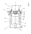
- the one in the only one FIG. 1 shown cogeneration plant consists initially in a known manner from a boiler 1 with a combustion chamber 2 for combustion of a fuel.
- This combustion chamber 2 is seen in the main flow direction (indicated by arrows) downstream of an exhaust 3 for the removal of an exhaust gas formed during combustion.
- the combined heat and power plant is made a hot gas engine 4 (in particular Stirling engine) with a heater head 5 designed for heat exchange with the exhaust gas.
- the fuel is the use of a fluid fuel provided, in particular oil, but also gas.
- FIG. 1 it can be seen, at one end of the combustion chamber 2, a burner 14 and at the other end of the combustion chamber 2, the heater head 5 is arranged.
- the combustion chamber 2 is cylindrical, wherein on one end face of the burner 14 and on the other end face of the heater head 5 is arranged.
- the heater head 5 is formed downstream of the exhaust gas 3 in the main flow direction of the exhaust gas seen.
- the heat transfer lamellae 10 are arranged like a wreath around a lamellar-free, preferably dome-shaped surface region 11 of the heater head 5.
- This lamellar surface area 11 of the heater head 5 is how FIG. 1 shows, formed with an outside of a preferably also dome-shaped combustion chamber 12 thermally connected.
- thermally related is to be understood that either the surface area 11 and the combustion chamber 12 directly touch or at least a material (such as nonwoven, stainless steel wool or the like) is disposed between the two components, which ensures good heat transfer.
- the combustion chamber 2 is provided away from the heater head with at least one opening 13 for the exhaust gas train 3.
- the exhaust gas 3 is formed as the combustion chamber 2 at least partially enclosing annular gap space and at least partially thermally connected with a water-carrying space 15, wherein the water-carrying space 15 is particularly preferred and formed as an annular gap the exhaust gas 3 is at least partially enclosing.
- the exhaust gas 3 is formed in a conventional manner as a heat exchanger, as a primary heat exchanger.
- main longitudinal axes of the combustion chamber 2, the exhaust gas duct 3 and the hot gas engine 4 are parallel to each other, here even superposed, formed.
- a shut-off element 6 is arranged between the exhaust gas 3 and the heater head 5.
- the heater head 5 is formed by a chamber 7 provided with openings 7 enclosed, wherein the exhaust gas 3 is formed via the openings 7 with the chamber 8 connectable.
- the shut-off element 6 is thus provided for closing on demand (this will be discussed below) of the openings 7.
- the shut-off element 6 (which is in FIG. 1 is not shown in detail) either temperature-dependent automatically (for example via a bimetal) or via a (mechanical or electromechanical) actuator operably formed.
- FIG. 1 illustrated preferably provided that the heater head 5 of the hot gas engine 4 between the exhaust 3 and a Nachschaltebenleyer 9 (secondary heat exchanger or second flue) is arranged.
- This Nachschaltebenleyer 9 is arranged at the heater head side end of the combustion chamber 2 and a helically wound coil heat exchanger, the heater head 5 at least partially enclosing and (as in the WO 2007/079730 A1 ) formed by the exhaust gas radially from the inside to the outside.
- the combined heat and power plant functions as follows:
- the burner 14 is used to burn a fluid fuel, in particular oil.
- the resulting exhaust gas flows in FIG. 1 from left to right in the combustion chamber 2.
- a Strömungsumschelement 16 may be arranged. With this Strömungsumschelement 16, the heat input of the burner 14 opposite end face of the combustion chamber 2 can be influenced. This may be necessary if the maximum amount of heat is not to be transferred to the combustion chamber wall 12 and thus to the lamellar-free surface area 11 of the heater head 5.
- the exhaust gas flows as a sheath flow back toward the burner 14 is deflected in the region of the burner 14 and passed through the opening 13 formed as an annular gap in the exhaust gas 3. Since the exhaust gas 3 is enclosed by a space 15 flowed through by the heating circuit water, the exhaust gas is cooled when passing through the exhaust gas train 3, which thus serves as a primary heat exchanger.
- the exhaust gas is in any case passed through the Nachschaltebenleyer 9 (second flue) to be further cooled there again.
- the exhaust gas can also flow into the chamber 8, in which the heating head 5 provided with heat-transfer fins 10 is located.
- the openings 7 In FIG. 1 are the openings 7 to about 1/4 to 1/3 closed. The position of the shut-off element 6 can influence how much heat is transferred to the heater head 5.
- shut-off element 6 releases the openings 7 at low power, ie the hot exhaust gas can transfer its heat to the chamber 8 and thus to the heat transfer plate 10 delivered. If the burner 14, however, operated at a higher power, the access to the chamber 8 is closed with the shut-off 6, because the heater head 5 is already supplied via the rear wall of the combustion chamber (combustion chamber 12) enough heat to ensure a constant hot gas engine operation.
Landscapes
- Engineering & Computer Science (AREA)
- Chemical & Material Sciences (AREA)
- Combustion & Propulsion (AREA)
- Mechanical Engineering (AREA)
- General Engineering & Computer Science (AREA)
- Physics & Mathematics (AREA)
- Thermal Sciences (AREA)
- Incineration Of Waste (AREA)
- Engine Equipment That Uses Special Cycles (AREA)
Claims (10)
- Installation de production combinée de chaleur et d'électricité comprenant une chaudière (1) avec une chambre de combustion (2) pour brûler un carburant, un conduit des gaz d'échappement (3) étant placée après la chambre de combustion (2) vue dans le sens d'écoulement pour évacuer un gaz d'échappement généré lors de la combustion et un moteur Stirling (4) avec une tête de réchauffeur (5) constituée pour l'échange de chaleur avec le gaz d'échappement, la tête de réchauffeur (5) étant constituée montée après le conduit de gaz d'échappement (3), vue dans le sens d'écoulement principal du gaz d'échappement, un brûleur (14) étant disposé à une extrémité de la chambre de combustion (2),
caractérisée en ce que
la tête de réchauffeur (5) est disposée à l'autre extrémité de la chambre de combustion (2). - Installation de production combinée de chaleur et d'électricité selon la revendication 1,
caractérisée en ce que
pour empêcher un échange de chaleur entre le gaz d'échappement et la tête de réchauffeur (5), un élément d'isolement (6) est placé entre le conduit de gaz d'échappement (3) et la tête de réchauffeur (5). - Installation de production combinée de chaleur et d'électricité selon la revendication 1 ou 2,
caractérisée en ce que
la tête de réchauffeur (5) est constituée entourée d'une chambre (8) munie d'ouvertures (7). - Installation de production combinée de chaleur et d'électricité selon la revendication 3,
caractérisée en ce que
le conduit de gaz d'échappement (3) est constitué comme pouvant être relié à la chambre (8) par les ouvertures (7). - Installation de production combinée de chaleur et d'électricité selon une quelconque des revendications 1 à 4,
caractérisée en ce que
la tête de réchauffeur (5) du moteur Stirling (4) est disposée entre le conduit de gaz d'échappement (3) et un échangeur de chaleur auxiliaire (9). - Installation de production combinée de chaleur et d'électricité selon la revendication 5,
caractérisée en ce que
l'échangeur de chaleur auxiliaire (9) est disposé à l'extrémité côté tête de réchauffeur de la chambre de combustion (2). - Installation de production combinée de chaleur et d'électricité selon une quelconque des revendications 1 à 6,
caractérisée en ce que
la tête de réchauffeur (5) comporte une pluralité de lamelles de transfert de chaleur (10) pour accroître la surface. - Installation de production combinée de chaleur et d'électricité selon la revendication 7,
caractérisée en ce que
les lamelles de transfert de chaleur (10) sont disposées en forme de couronne autour d'une zone de surface (11) sans lamelle de la tête de réchauffeur (5). - Installation de production combinée de chaleur et d'électricité selon la revendication 7 ou 8,
caractérisée en ce que
la zone de surface (11) sans lamelle de la tête de réchauffeur (5) est constituée thermiquement en contact avec un côté extérieur d'une paroi de chambre de combustion (12). - Installation de production combinée de chaleur et d'électricité selon une quelconque des revendications 1 à 9,
caractérisée en ce que
la chambre de combustion (2) est, munie à l'opposé de la tête de réchauffeur, d'une ouverture (13) vers le conduit de gaz d'échappement (3).
Applications Claiming Priority (1)
| Application Number | Priority Date | Filing Date | Title |
|---|---|---|---|
| DE102011106617A DE102011106617A1 (de) | 2011-06-16 | 2011-06-16 | Kraft-Wärme-Kopplungsanlage |
Publications (2)
| Publication Number | Publication Date |
|---|---|
| EP2535546A1 EP2535546A1 (fr) | 2012-12-19 |
| EP2535546B1 true EP2535546B1 (fr) | 2014-10-08 |
Family
ID=46197142
Family Applications (1)
| Application Number | Title | Priority Date | Filing Date |
|---|---|---|---|
| EP12170885.3A Not-in-force EP2535546B1 (fr) | 2011-06-16 | 2012-06-05 | Installation de production combinée de chaleur et d'électricité |
Country Status (2)
| Country | Link |
|---|---|
| EP (1) | EP2535546B1 (fr) |
| DE (1) | DE102011106617A1 (fr) |
Families Citing this family (1)
| Publication number | Priority date | Publication date | Assignee | Title |
|---|---|---|---|---|
| IT201600114405A1 (it) * | 2016-11-14 | 2018-05-14 | Calini Donatella | Una camera di combustione e assorbitore di calore per motori stirling in configurazione alfa |
Family Cites Families (10)
| Publication number | Priority date | Publication date | Assignee | Title |
|---|---|---|---|---|
| JPS58221340A (ja) * | 1982-06-16 | 1983-12-23 | Sanden Corp | スタ−リングエンジン利用のガス瞬間湯沸器 |
| DE3502308A1 (de) * | 1984-01-19 | 1985-10-10 | Klaus Ing Grad Kramer | Dezentrale stromversorgung durch waerme-stromkopplung mit stirling-motor |
| DE3516962A1 (de) * | 1985-05-10 | 1986-11-13 | Messerschmitt-Bölkow-Blohm GmbH, 8012 Ottobrunn | Oel- oder gasbefeuerte warmwasser-hausheizung |
| JPH0719008A (ja) * | 1993-06-30 | 1995-01-20 | Aisin Seiki Co Ltd | スターリングエンジン用加熱装置 |
| AT408159B (de) * | 1998-10-16 | 2001-09-25 | Vaillant Gmbh | Einrichtung mit mindestens einer brennstoffzelle |
| GB0020012D0 (en) * | 2000-08-15 | 2000-10-04 | Bg Intellectual Pty Ltd | Heat transfer head for a stirling engine |
| US20020084065A1 (en) * | 2001-01-04 | 2002-07-04 | Tamin Enterprises | Fluid heat exchanger |
| US20060026835A1 (en) * | 2004-08-03 | 2006-02-09 | Wood James G | Heat exchanger fins and method for fabricating fins particularly suitable for stirling engines |
| DE102006001590A1 (de) | 2006-01-11 | 2007-07-12 | Viessmann Werke Gmbh & Co Kg | Heizkessel |
| DE202010011591U1 (de) * | 2010-08-20 | 2010-10-28 | Robert Bosch Gmbh | Vorrichtung zum Beheizen eines Wärmetauschers einer Wärmekraftmaschine sowie Verbrennungsheizanlage mit Wärmekraftmaschine |
-
2011
- 2011-06-16 DE DE102011106617A patent/DE102011106617A1/de not_active Ceased
-
2012
- 2012-06-05 EP EP12170885.3A patent/EP2535546B1/fr not_active Not-in-force
Also Published As
| Publication number | Publication date |
|---|---|
| EP2535546A1 (fr) | 2012-12-19 |
| DE102011106617A1 (de) | 2012-12-20 |
Similar Documents
| Publication | Publication Date | Title |
|---|---|---|
| EP3301378B1 (fr) | Tuyau de transfert de chaleur et chaudière dotée d'un tel tuyau de transfert de chaleur | |
| EP2413080A2 (fr) | Dispositif de refroidissement pour un moteur à combustion interne | |
| DE60305277T2 (de) | Effizienter Wärmetauscher und Brennkammer-Anordnung für Kessel und Lufterhitzer | |
| DE2447006C2 (de) | Gasturbinenanlage mit einer Dichtungseinrichtung zwischen Brennkammer und Turbineneintrittsleitkranz | |
| EP1899654B1 (fr) | Chaudière de chauffage | |
| DE1802196A1 (de) | Brennereinheit fuer Heizkoerper | |
| EP2313698B1 (fr) | Chaudière sectionnée en fonte ou en aluminium | |
| EP2535546B1 (fr) | Installation de production combinée de chaleur et d'électricité | |
| EP4063733B1 (fr) | Appareil de chauffage avec un dispositif permettant de réduire les conséquences d'un retour de flamme dans un brûleur à prémélange de l'appareil de chauffage | |
| DD149698A5 (de) | Mit feststoffen und mit fluessig-brennstoffen beheizbarer mehrbereichsverbrennungsofen | |
| DE3413968A1 (de) | Vorrichtung zur verbrennungsunterstuetzung fuer einen oel- oder gasbrenner | |
| DE202009011326U1 (de) | Wärmetauscher für den Rauchgaskanal einer Feuerung | |
| DE102011053011B4 (de) | Kraft-Wärme-Kopplungsanlage | |
| EP1698839B1 (fr) | Chaudière | |
| DE3205121C2 (de) | Heizungskessel | |
| EP1221571B1 (fr) | Appareil de combustion avec refroidissement | |
| EP3096093B1 (fr) | Appareil de chauffage | |
| CH657912A5 (de) | Gasbeheizte kesselanlage. | |
| DE202004008763U1 (de) | Heizkessel | |
| EP2462334A1 (fr) | Dispositif de préchauffage destiné à préchauffer du carburant à l'état liquide et/ou gazeux pour un moteur à combustion interne | |
| DE69200149T2 (de) | Gasbetriebener Wasserrohrkessel. | |
| EP0059898A2 (fr) | Méthode pour l'utilisation d'une installation de chauffage central à eau chaude avec un échangeur de chaleur séparé pour les gaz de combustion | |
| DE2919306C3 (de) | Heizkessel und Verfahren zum Betrieb desselben | |
| EP4695569A1 (fr) | Échangeur de chaleur | |
| EP4226081A1 (fr) | Dispositif destiné à chauffer un milieu |
Legal Events
| Date | Code | Title | Description |
|---|---|---|---|
| PUAI | Public reference made under article 153(3) epc to a published international application that has entered the european phase |
Free format text: ORIGINAL CODE: 0009012 |
|
| AK | Designated contracting states |
Kind code of ref document: A1 Designated state(s): AL AT BE BG CH CY CZ DE DK EE ES FI FR GB GR HR HU IE IS IT LI LT LU LV MC MK MT NL NO PL PT RO RS SE SI SK SM TR |
|
| AX | Request for extension of the european patent |
Extension state: BA ME |
|
| 17P | Request for examination filed |
Effective date: 20130617 |
|
| RBV | Designated contracting states (corrected) |
Designated state(s): AL AT BE BG CH CY CZ DE DK EE ES FI FR GB GR HR HU IE IS IT LI LT LU LV MC MK MT NL NO PL PT RO RS SE SI SK SM TR |
|
| 17Q | First examination report despatched |
Effective date: 20130717 |
|
| GRAP | Despatch of communication of intention to grant a patent |
Free format text: ORIGINAL CODE: EPIDOSNIGR1 |
|
| INTG | Intention to grant announced |
Effective date: 20140625 |
|
| GRAS | Grant fee paid |
Free format text: ORIGINAL CODE: EPIDOSNIGR3 |
|
| GRAA | (expected) grant |
Free format text: ORIGINAL CODE: 0009210 |
|
| AK | Designated contracting states |
Kind code of ref document: B1 Designated state(s): AL AT BE BG CH CY CZ DE DK EE ES FI FR GB GR HR HU IE IS IT LI LT LU LV MC MK MT NL NO PL PT RO RS SE SI SK SM TR |
|
| REG | Reference to a national code |
Ref country code: GB Ref legal event code: FG4D Free format text: NOT ENGLISH |
|
| REG | Reference to a national code |
Ref country code: AT Ref legal event code: REF Ref document number: 690775 Country of ref document: AT Kind code of ref document: T Effective date: 20141015 Ref country code: CH Ref legal event code: NV Representative=s name: PATENTANWALTSBUERO DR. URS FALK, CH Ref country code: CH Ref legal event code: EP |
|
| REG | Reference to a national code |
Ref country code: IE Ref legal event code: FG4D Free format text: LANGUAGE OF EP DOCUMENT: GERMAN |
|
| REG | Reference to a national code |
Ref country code: DE Ref legal event code: R096 Ref document number: 502012001384 Country of ref document: DE Effective date: 20141120 |
|
| REG | Reference to a national code |
Ref country code: NL Ref legal event code: T3 |
|
| REG | Reference to a national code |
Ref country code: LT Ref legal event code: MG4D |
|
| PG25 | Lapsed in a contracting state [announced via postgrant information from national office to epo] |
Ref country code: ES Free format text: LAPSE BECAUSE OF FAILURE TO SUBMIT A TRANSLATION OF THE DESCRIPTION OR TO PAY THE FEE WITHIN THE PRESCRIBED TIME-LIMIT Effective date: 20141008 Ref country code: FI Free format text: LAPSE BECAUSE OF FAILURE TO SUBMIT A TRANSLATION OF THE DESCRIPTION OR TO PAY THE FEE WITHIN THE PRESCRIBED TIME-LIMIT Effective date: 20141008 Ref country code: PT Free format text: LAPSE BECAUSE OF FAILURE TO SUBMIT A TRANSLATION OF THE DESCRIPTION OR TO PAY THE FEE WITHIN THE PRESCRIBED TIME-LIMIT Effective date: 20150209 Ref country code: LT Free format text: LAPSE BECAUSE OF FAILURE TO SUBMIT A TRANSLATION OF THE DESCRIPTION OR TO PAY THE FEE WITHIN THE PRESCRIBED TIME-LIMIT Effective date: 20141008 Ref country code: NO Free format text: LAPSE BECAUSE OF FAILURE TO SUBMIT A TRANSLATION OF THE DESCRIPTION OR TO PAY THE FEE WITHIN THE PRESCRIBED TIME-LIMIT Effective date: 20150108 Ref country code: IS Free format text: LAPSE BECAUSE OF FAILURE TO SUBMIT A TRANSLATION OF THE DESCRIPTION OR TO PAY THE FEE WITHIN THE PRESCRIBED TIME-LIMIT Effective date: 20150208 |
|
| PG25 | Lapsed in a contracting state [announced via postgrant information from national office to epo] |
Ref country code: PL Free format text: LAPSE BECAUSE OF FAILURE TO SUBMIT A TRANSLATION OF THE DESCRIPTION OR TO PAY THE FEE WITHIN THE PRESCRIBED TIME-LIMIT Effective date: 20141008 Ref country code: CY Free format text: LAPSE BECAUSE OF FAILURE TO SUBMIT A TRANSLATION OF THE DESCRIPTION OR TO PAY THE FEE WITHIN THE PRESCRIBED TIME-LIMIT Effective date: 20141008 Ref country code: HR Free format text: LAPSE BECAUSE OF FAILURE TO SUBMIT A TRANSLATION OF THE DESCRIPTION OR TO PAY THE FEE WITHIN THE PRESCRIBED TIME-LIMIT Effective date: 20141008 Ref country code: SE Free format text: LAPSE BECAUSE OF FAILURE TO SUBMIT A TRANSLATION OF THE DESCRIPTION OR TO PAY THE FEE WITHIN THE PRESCRIBED TIME-LIMIT Effective date: 20141008 Ref country code: RS Free format text: LAPSE BECAUSE OF FAILURE TO SUBMIT A TRANSLATION OF THE DESCRIPTION OR TO PAY THE FEE WITHIN THE PRESCRIBED TIME-LIMIT Effective date: 20141008 Ref country code: GR Free format text: LAPSE BECAUSE OF FAILURE TO SUBMIT A TRANSLATION OF THE DESCRIPTION OR TO PAY THE FEE WITHIN THE PRESCRIBED TIME-LIMIT Effective date: 20150109 Ref country code: LV Free format text: LAPSE BECAUSE OF FAILURE TO SUBMIT A TRANSLATION OF THE DESCRIPTION OR TO PAY THE FEE WITHIN THE PRESCRIBED TIME-LIMIT Effective date: 20141008 |
|
| REG | Reference to a national code |
Ref country code: DE Ref legal event code: R097 Ref document number: 502012001384 Country of ref document: DE |
|
| PG25 | Lapsed in a contracting state [announced via postgrant information from national office to epo] |
Ref country code: DK Free format text: LAPSE BECAUSE OF FAILURE TO SUBMIT A TRANSLATION OF THE DESCRIPTION OR TO PAY THE FEE WITHIN THE PRESCRIBED TIME-LIMIT Effective date: 20141008 Ref country code: EE Free format text: LAPSE BECAUSE OF FAILURE TO SUBMIT A TRANSLATION OF THE DESCRIPTION OR TO PAY THE FEE WITHIN THE PRESCRIBED TIME-LIMIT Effective date: 20141008 Ref country code: CZ Free format text: LAPSE BECAUSE OF FAILURE TO SUBMIT A TRANSLATION OF THE DESCRIPTION OR TO PAY THE FEE WITHIN THE PRESCRIBED TIME-LIMIT Effective date: 20141008 Ref country code: RO Free format text: LAPSE BECAUSE OF FAILURE TO SUBMIT A TRANSLATION OF THE DESCRIPTION OR TO PAY THE FEE WITHIN THE PRESCRIBED TIME-LIMIT Effective date: 20141008 Ref country code: SK Free format text: LAPSE BECAUSE OF FAILURE TO SUBMIT A TRANSLATION OF THE DESCRIPTION OR TO PAY THE FEE WITHIN THE PRESCRIBED TIME-LIMIT Effective date: 20141008 |
|
| PLBE | No opposition filed within time limit |
Free format text: ORIGINAL CODE: 0009261 |
|
| STAA | Information on the status of an ep patent application or granted ep patent |
Free format text: STATUS: NO OPPOSITION FILED WITHIN TIME LIMIT |
|
| 26N | No opposition filed |
Effective date: 20150709 |
|
| PG25 | Lapsed in a contracting state [announced via postgrant information from national office to epo] |
Ref country code: MC Free format text: LAPSE BECAUSE OF FAILURE TO SUBMIT A TRANSLATION OF THE DESCRIPTION OR TO PAY THE FEE WITHIN THE PRESCRIBED TIME-LIMIT Effective date: 20141008 |
|
| PG25 | Lapsed in a contracting state [announced via postgrant information from national office to epo] |
Ref country code: LU Free format text: LAPSE BECAUSE OF FAILURE TO SUBMIT A TRANSLATION OF THE DESCRIPTION OR TO PAY THE FEE WITHIN THE PRESCRIBED TIME-LIMIT Effective date: 20150605 Ref country code: SI Free format text: LAPSE BECAUSE OF FAILURE TO SUBMIT A TRANSLATION OF THE DESCRIPTION OR TO PAY THE FEE WITHIN THE PRESCRIBED TIME-LIMIT Effective date: 20141008 |
|
| REG | Reference to a national code |
Ref country code: IE Ref legal event code: MM4A |
|
| PG25 | Lapsed in a contracting state [announced via postgrant information from national office to epo] |
Ref country code: IE Free format text: LAPSE BECAUSE OF NON-PAYMENT OF DUE FEES Effective date: 20150605 |
|
| REG | Reference to a national code |
Ref country code: FR Ref legal event code: PLFP Year of fee payment: 5 |
|
| PGFP | Annual fee paid to national office [announced via postgrant information from national office to epo] |
Ref country code: GB Payment date: 20160617 Year of fee payment: 5 Ref country code: DE Payment date: 20160602 Year of fee payment: 5 |
|
| PGFP | Annual fee paid to national office [announced via postgrant information from national office to epo] |
Ref country code: NL Payment date: 20160610 Year of fee payment: 5 |
|
| PGFP | Annual fee paid to national office [announced via postgrant information from national office to epo] |
Ref country code: CH Payment date: 20160727 Year of fee payment: 5 Ref country code: IT Payment date: 20160624 Year of fee payment: 5 |
|
| PG25 | Lapsed in a contracting state [announced via postgrant information from national office to epo] |
Ref country code: MT Free format text: LAPSE BECAUSE OF FAILURE TO SUBMIT A TRANSLATION OF THE DESCRIPTION OR TO PAY THE FEE WITHIN THE PRESCRIBED TIME-LIMIT Effective date: 20141008 |
|
| PGFP | Annual fee paid to national office [announced via postgrant information from national office to epo] |
Ref country code: FR Payment date: 20160708 Year of fee payment: 5 |
|
| PG25 | Lapsed in a contracting state [announced via postgrant information from national office to epo] |
Ref country code: SM Free format text: LAPSE BECAUSE OF FAILURE TO SUBMIT A TRANSLATION OF THE DESCRIPTION OR TO PAY THE FEE WITHIN THE PRESCRIBED TIME-LIMIT Effective date: 20141008 Ref country code: HU Free format text: LAPSE BECAUSE OF FAILURE TO SUBMIT A TRANSLATION OF THE DESCRIPTION OR TO PAY THE FEE WITHIN THE PRESCRIBED TIME-LIMIT; INVALID AB INITIO Effective date: 20120605 Ref country code: BG Free format text: LAPSE BECAUSE OF FAILURE TO SUBMIT A TRANSLATION OF THE DESCRIPTION OR TO PAY THE FEE WITHIN THE PRESCRIBED TIME-LIMIT Effective date: 20141008 |
|
| PG25 | Lapsed in a contracting state [announced via postgrant information from national office to epo] |
Ref country code: BE Free format text: LAPSE BECAUSE OF NON-PAYMENT OF DUE FEES Effective date: 20150630 |
|
| PG25 | Lapsed in a contracting state [announced via postgrant information from national office to epo] |
Ref country code: TR Free format text: LAPSE BECAUSE OF FAILURE TO SUBMIT A TRANSLATION OF THE DESCRIPTION OR TO PAY THE FEE WITHIN THE PRESCRIBED TIME-LIMIT Effective date: 20141008 |
|
| REG | Reference to a national code |
Ref country code: DE Ref legal event code: R119 Ref document number: 502012001384 Country of ref document: DE |
|
| REG | Reference to a national code |
Ref country code: CH Ref legal event code: PL |
|
| REG | Reference to a national code |
Ref country code: NL Ref legal event code: MM Effective date: 20170701 |
|
| GBPC | Gb: european patent ceased through non-payment of renewal fee |
Effective date: 20170605 |
|
| PG25 | Lapsed in a contracting state [announced via postgrant information from national office to epo] |
Ref country code: NL Free format text: LAPSE BECAUSE OF NON-PAYMENT OF DUE FEES Effective date: 20170701 |
|
| REG | Reference to a national code |
Ref country code: FR Ref legal event code: ST Effective date: 20180228 |
|
| PG25 | Lapsed in a contracting state [announced via postgrant information from national office to epo] |
Ref country code: GB Free format text: LAPSE BECAUSE OF NON-PAYMENT OF DUE FEES Effective date: 20170605 Ref country code: LI Free format text: LAPSE BECAUSE OF NON-PAYMENT OF DUE FEES Effective date: 20170630 Ref country code: CH Free format text: LAPSE BECAUSE OF NON-PAYMENT OF DUE FEES Effective date: 20170630 Ref country code: DE Free format text: LAPSE BECAUSE OF NON-PAYMENT OF DUE FEES Effective date: 20180103 |
|
| PG25 | Lapsed in a contracting state [announced via postgrant information from national office to epo] |
Ref country code: IT Free format text: LAPSE BECAUSE OF NON-PAYMENT OF DUE FEES Effective date: 20170605 Ref country code: FR Free format text: LAPSE BECAUSE OF NON-PAYMENT OF DUE FEES Effective date: 20170630 |
|
| PG25 | Lapsed in a contracting state [announced via postgrant information from national office to epo] |
Ref country code: MK Free format text: LAPSE BECAUSE OF FAILURE TO SUBMIT A TRANSLATION OF THE DESCRIPTION OR TO PAY THE FEE WITHIN THE PRESCRIBED TIME-LIMIT Effective date: 20141008 |
|
| REG | Reference to a national code |
Ref country code: AT Ref legal event code: MM01 Ref document number: 690775 Country of ref document: AT Kind code of ref document: T Effective date: 20170605 |
|
| PG25 | Lapsed in a contracting state [announced via postgrant information from national office to epo] |
Ref country code: AL Free format text: LAPSE BECAUSE OF FAILURE TO SUBMIT A TRANSLATION OF THE DESCRIPTION OR TO PAY THE FEE WITHIN THE PRESCRIBED TIME-LIMIT Effective date: 20141008 |
|
| PG25 | Lapsed in a contracting state [announced via postgrant information from national office to epo] |
Ref country code: AT Free format text: LAPSE BECAUSE OF NON-PAYMENT OF DUE FEES Effective date: 20170605 |