EP2540931A2 - Elément de surélévation pour puits de lumière - Google Patents
Elément de surélévation pour puits de lumière Download PDFInfo
- Publication number
- EP2540931A2 EP2540931A2 EP12173787A EP12173787A EP2540931A2 EP 2540931 A2 EP2540931 A2 EP 2540931A2 EP 12173787 A EP12173787 A EP 12173787A EP 12173787 A EP12173787 A EP 12173787A EP 2540931 A2 EP2540931 A2 EP 2540931A2
- Authority
- EP
- European Patent Office
- Prior art keywords
- lichtschachtaufstockelement
- light shaft
- lichtschachtaufstockelements
- light
- hollow profile
- Prior art date
- Legal status (The legal status is an assumption and is not a legal conclusion. Google has not performed a legal analysis and makes no representation as to the accuracy of the status listed.)
- Granted
Links
Images

Classifications
-
- E—FIXED CONSTRUCTIONS
- E04—BUILDING
- E04F—FINISHING WORK ON BUILDINGS, e.g. STAIRS, FLOORS
- E04F17/00—Vertical ducts; Channels, e.g. for drainage
- E04F17/06—Light shafts, e.g. for cellars
Definitions
- the invention relates to a Lichtschachtetzstockelement according to claim 1 and a method for variable topping up a light shaft by means of a Lichtschachtetzstockelements according to claim 12.
- the invention is based on the object to show a Lichtschachtetzstockelement that can be easily installed technically.
- the object is achieved by a Lichtschachtetzstockelement for replenishing a light shaft, wherein the Lichtschachtillerstockelement has a hollow profile substantially, and the Lichtschachtillerelement is attached / fastened exclusively on the light shaft.
- An essential point of the invention is that the Lichtschachtetzstockelement has a hollow profile, and that the Lichtschachtillerstockelement is attached or fastened only on the light shaft and thus not on the basement wall.
- a lower edge of the Lichtschachtaufstockelements may be tapered towards the light well.
- the Aufstock the Lichtschachtillerstockelements can be changed after installation.
- the pointed lower edge makes it possible to push the Lichtschachtillerstockelement in the (earth) floor and thereby reduce the Aufstock too, even after the Lichtschachtetzstockelement has already been installed.
- the light well header further includes a support projection for supporting a mesh cover for an upper well opening of the light well.
- the Lichtschachtetzstockelement with the light shaft can be screwed, in particular releasably screwed.
- the technical complexity for fixing the Lichtschachtillerstockelements decreases at the light shaft.
- the assembly time is reduced.
- the Aufstock Abu can also be changed after installation or attachment of Lichtschachtetzstockelements.
- the Lichtschachtetzstockelement is independent of a Theorystock Oust., around which the Lichtschachtetzstockelement in use over an upper edge of the light shaft, at the same location of the light shaft fastened. This makes it possible to adjust the Aufstock Hab the Lichtschachtetzstockelements continuously. In addition, the technical effort for the attachment decreases.
- the Lichtschachtankelement may substantially completely enclose an upper edge of the light shaft.
- the Lichtschachtetzstockelement is formed such that the light shaft can be increased by about 3 cm to about 32 cm above the upper edge of the light shaft through the Lichtschachtillerelement infinitely.
- the hollow profile of the Lichtschachtetzstockelements in particular the hollow profile of the support projection of Lichtschachtetzstockelements, may be formed for receiving at least one stiffening element for stiffening the Lichtschachtetzstockelements.
- An advantage of this is that the previously known metal stiffening frame for the light shaft are no longer needed. As a result, the weight of the Lichtschachtetzstockelements further decreases.
- the rigidity of the Lichtschachtetzstockelements can be variably adjusted taking into account the weight.
- the Lichtschachtetzstockelement may further comprise at least one stiffening element for stiffening the Lichtschachtetzstockelements, wherein the stiffening element in the hollow profile, in particular in the hollow profile of the support projection, is arranged. Due to the stiffening element, the stability and rigidity of the Lichtschachtetzstockelements is substantially increased. By the factory arrangement one or more stiffening elements makes on-site installation easier or faster.
- the Lichtschachtetzstockelement may be colored or colored in whole or in part.
- the visible after installation edges of Lichtschachtillerstock may be to the environment, for. Plates or tiles, colored.
- a colored edge e.g. be attached to the element in the area of the later grid cover.
- the Lichtschachtetzstockelement is formed such that the upper end of the Lichtschachtaufstock elements in use by means of the Aufstocklage can be very accurately adapted to the circumstances of the installation site, in particular to crooked earth surfaces, in use.
- small entanglements of the main axes of the light shaft extension element with respect to the main axes of the light shaft are possible.
- modifications e.g., sawing
- large entanglements can be achieved, and thus the augmentation element can adapt to the circumstances, e.g. a strong terrain waste, adapt.
- the Lichtschachtaufstockelement can be used to replenish a fixed Lichtschachtillerstockelements that replaces a light well.
- variable Lichtschachtillerstockelement can be combined with a fixed and non-variable Lichtschachtillerstockelement and to connect the fixed Lichtschachtillerstockelement on its underside with the light well and on its upper side with the variable light well element.
- Fixed light shaft extension elements are light shaft extension elements which have a predetermined and unchangeable height. To compensate for height differences, then e.g. one or more fixed Lichtschachtillerstock comprise be combined with a variable Lichtschachtetzstockelement.
- the object is also achieved by a method for variable heightening of a light shaft by means of a Lichtschachtillerelements with hollow profile, comprising the following steps: arranging the Lichtschachtillerstockelements on the light shaft such that the Lichtschachtillerstockelement protrudes a first Aufgeunter Why over an upper edge of the light shaft, and attaching the Lichtschachtillerstockelements exclusively on the light shaft.
- An advantage of this is that the mounting of the Lichtschachtetzstockelements is greatly simplified.
- the Lichtschachtetzstockelement can already be factory attached to the light shaft.
- Another advantage is that in this method, the light well must be less stable, since the Lichtschachtetzstockelement is lightweight because it has a hollow profile.
- the Lichtschachtetzstockelement can be attached to the light shaft by screwing, in particular exclusively by screwing. As a result, the technical complexity for fixing the Lichtschachtetzstockelements decreases at the light shaft. In addition, the assembly time is reduced.
- the method may further comprise the following steps: introducing at least one stiffening element into the hollow profile of the light shaft extension element, in particular into the hollow profile of a support projection for supporting a grate cover for an upper shaft opening of the light shaft, for stiffening the light shaft extension element.
- the method furthermore comprises the following steps after fastening the light shaft: releasing the fastening between the light shaft extension element and the light shaft, steplessly moving the light shaft extension element such that the light shaft extension element projects beyond the upper edge of the light shaft over a second extension height, wherein the second extension height of the first Maugeunter Why differs, and re-attaching the Lichtschachtetzstockelements on the second Aufgeunter Why exclusively on the light shaft.
- Fig. 1 shows a schematic side / cross-sectional view of an embodiment of Lichtschachtillerstockelements invention 1.
- the Lichtschachtetzstockelement 1 serves to increase a light shaft 30.
- Aufstock means in the context of this invention that the light shaft 30 is extended in height.
- the light shaft 30 serves to let light to a basement window 45 in a building wall 40.
- the light shaft 30 is attached to the building wall 40.
- the increase of the light shaft 30 is particularly necessary if the upper edge 32 of the light shaft 30 is below the (planned) earth surface. It must be prevented that soil or other Erdzanbegrenzungen get into the light shaft 30.
- the light shaft extension element 1 serves for this purpose. The light shaft extension element 1 lengthens the light shaft 30 in the height or stalls it.
- the Lichtschachtetzstockelement 1 has a tapered lower edge 4.
- This tapered edge 4 it is possible to press the Lichtschachtaufstockelement 1 deeper into the earth even after installation of Lichtschachtetzstockelements 1. As a result, the Maustock Abu is reduced.
- the tapered edge 4 displaces the earth to the side.
- the raised floor is in Fig. 1 and in Fig. 2 indicated by the h symbol.
- the mounting height h is the distance between the upper end of the Lichtschachtetzstockelements 1 and the upper edge 32 of the light shaft 30th
- the Lichtschachtetzstockelement 1 is fixed by means of a screw 20 or more screws at the upper edge 33 of the light shaft 30. This compound is preferably releasable again.
- the Lichtschachtetzstockelement 1 is exclusively attached to the light shaft 30 or fastened. As a result, (unwanted) thermal bridges between the Lichtschachtillerstockelement 1 and the basement wall 40 are avoided. In addition, the Lichtschachtaufstockelement 1 can be easily fixed technically. In addition, the Lichtschachtetzstockelement 1 factory already attached to the light shaft 30. This saves time for on-site attachment.
- the Lichtschachtetzstockelement 1 is fixed by the Lichtschachtillerelement 1 is arranged such that the Lichtschachtillerelement 1 the desired Aufstock Boy over the upper edge 32 of the light shaft 30 protrudes. Thereafter, the Lichtschachtillerelement 1 is attached exclusively to the light shaft 30. This is preferably done by means of the screw 20. Other types of attachment, in particular by means of adhesives, etc., are conceivable.
- the Lichtschachtetzstockelement 1 preferably has no special fastening devices. However, it is also conceivable that the Lichtschachtetzstockelement 1 has special fastening devices.
- the screw 20 is simply screwed from the direction of the upper edge 33 of the light shaft 30 in the Lichtschachtetzstockelement 1. It is possible to loosen the attachment or the screw 20 again to change the Aufstock amount. For this purpose, after loosening the screw 20, the Lichtschachtillerstockelement 1 either pulled out of the ground to increase the Maustock Way, or pressed into the ground to reduce the Aufstock endeavor. Thereafter, the screw 20 is screwed back to the same position of the light shaft 30, namely at the upper edge 33 of the light shaft with the Lichtschachtetzstockelement 1. The location of the Lichtschachtetzstockelement 1, at which the Lichtschachtetzstockelement 1 is connected with the light shaft 30, this has of course changed.
- the light shaft extension element 1 has no special fastening means, the light shaft extension element 1 can be connected or screwed to the light shaft 30 at any point of the light shaft extension element 1.
- the fastening point on the light shaft 30, on which the light shaft extension element 1 is screwed to the light shaft 30, is independent of the extension height of the light shaft extension element 1.
- the Lichtschachtetzstockelement 1 allows a stepless height adjustment, i. a continuous Aufstock Abu of about 3 cm to about 32 cm.
- the manner of mounting also allows the light well accumulator 1 to be used in situ or at the factory in depth, i. can be shortened below, provided, for example, the base, the insulation or clinker in the region of Lichtschachtetzstockelements 1 projects or projects.
- the Lichtschachtetzstockelement 1 also has a support projection 15.
- the support projection 15 is circumferential.
- a grid cover 50 is stored on the support projection 15.
- the grating cover 50 covers the upper shaft opening 35 of the light shaft 30 and prevents coarse dirt or the like from entering the light shaft 30.
- the Lichtschachtetzstockelement 1 encloses an upper edge 32 and the upper edge 33 of the light shaft 30 substantially completely.
- the light shaft 30 or the upper edge 33 of the light shaft 30 has a rectangular shape as a rule, wherein one side of the rectangular light shaft 30 is open, which faces the building wall 40 in use.
- the Lichtschachtetzstockelement 1 accordingly also has a rectangular shape, which is open to one side, namely in use to the building wall 40, so that the upper edge 32 and the upper edge 33 of the light shaft 30 is completely enclosed. This increases the stability of the light shaft.
- the grid cover 50 is supported on three sides. In addition, it is achieved that the grid cover 50 can be supported or stored without the grid cover 50 is in direct contact with the basement wall 40. As a result, thermal bridges between the grid cover 50 and the basement wall 40 are prevented.
- Fig. 2 shows an enlarged view of the area II of the Lichtschachtillerstockelements Fig. 1 ,
- the Lichtschachtetzstockelement 1 has a hollow profile or hollow chamber profile. This means that the Lichtschachtillerelement 1 has very many and quite large cavities 6. A large part of the inner volume of Lichtschachtillerelements 1 is thus hollow or empty.
- the cavities 6 preferably have in cross section a rectangular shape with rounded corners and are evenly distributed. At each level below the support projection 15 of Lichtschachtetzstockelement 1 exactly one cavity is arranged. However, it is also conceivable that a plurality of cavities are arranged at a height next to each other.
- the screw 20 extends through the upper edge 33 of the light shaft 30, penetrates through a first (inner) outer wall of Lichtschachtillerstockelements 1 in Lichtschachtaufstockelement 1, passes through a cavity 6 of Lichtschachtillerstockelements 1 and then in the first outer wall opposite (outer) wall of the Lichtschachtillerstockelements 1 ends. It is also conceivable that the screw 20 two cavities 6 of Lichtschachtetzstockelements 1 tangent or none of the cavities 6 tangent.
- the Lichtschachtetzstockelement 1 has in its support projection 15 a receptacle 7, i. a particularly large cavity, for a stiffening element 8.
- the stiffening element 8 may in particular be a so-called flat iron. In this way, the Lichtschachtaufstockelement 1, in particular the support projection 15, amplified.
- the stiffening element 8 or flat iron may consist of a metal or a metal alloy. Other materials, such as Plastics are conceivable.
- the stiffening element 8 can already be arranged at the factory in the light shaft extension element 1 or can be used on site depending on the desired strength, taking into account the resulting weight of Lichtschachtetzstockelements 1 in the Lichtschachtetzstockelement 1 or not.
- the flat iron or stiffening element 8 has a length which substantially corresponds to the length of an edge of the light shaft extension element 1. It is also conceivable that other parts of the Lichtschachtankstockelements have receptacles for stiffening elements 8.
- the Lichtschachtetzstockelement 1 is prepared by extrusion and can be cut exactly to the required size and / or assembled from several parts or welded together. Thus, only one tool is needed for different Lichtschachtetzstockelement gloves, which means a significant cost savings.
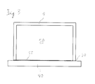
- Fig. 3 shows a plan view of an embodiment of Lichtschachtetzstockelements invention 1.
- the Lichtschachtetzstockelement 1 has the shape of a rectangle, which is open to one side, namely in use to the basement wall 40 out.
- the Lichtschachtetzstockelement 1 encloses the upper edge 32 and the upper edge 33 of the light shaft 30. As a result, the rigidity of the light shaft 30 is increased.
- the support projection 15 extends all around on the inside of the Lichtschachtetzstockelements 1.
- the grid cover 50 thus rests on three sides on the support projection 15 of Lichtschachtetzstockelements 1. Between the grid cover 50 and the building wall 40 is a gap 55. A small part of the light shaft 30, namely the part which is attached to the building wall 40 is in Fig. 3 also visible.
- the Lichtschachtankelement 1 is preferably made of PVC. Other materials, in particular other plastics are conceivable.
- the Lichtschachtetzstockelement 1 has a length, in use from top to bottom extending, of about 340 mm.
- the lower edge of the support projection 15 has a distance of about 309.5 mm to the lower edge of the Lichtschachtetzstockelement 1.
- the width of the Lichtschachtetzstockelement 1 is in the region below the support projection 15 is about 10 mm and above the support projection 15 is about 17.5 mm.
- the area of the Lichtschachtetzstockelement 1 above the support projection 15 has a height of about 19 mm.
- the support projection 15 has a height of about 12 mm.
- the support projection 15 protrudes approximately 32.5 mm in relation to the region of the light shaft extension element 1 below the support projection 15.
- the cavities 6 have a height of about 9 mm.
- the ribs within the Lichtschachtaufstockelement 1, is about 1 mm.
- the (outer) walls of Lichtschachtetzstockelement 1 have a thickness of about 2 mm.
- the flat iron or stiffening element 8 has a thickness of about 4 mm and a width of about 30 mm.
Landscapes
- Engineering & Computer Science (AREA)
- Architecture (AREA)
- Civil Engineering (AREA)
- Structural Engineering (AREA)
- Buildings Adapted To Withstand Abnormal External Influences (AREA)
- Shafts, Cranks, Connecting Bars, And Related Bearings (AREA)
- Golf Clubs (AREA)
- Residential Or Office Buildings (AREA)
- Fencing (AREA)
Priority Applications (1)
| Application Number | Priority Date | Filing Date | Title |
|---|---|---|---|
| PL12173787T PL2540931T3 (pl) | 2011-06-30 | 2012-06-27 | Element przedłużający dla świetlika |
Applications Claiming Priority (1)
| Application Number | Priority Date | Filing Date | Title |
|---|---|---|---|
| DE102011051484.8A DE102011051484B4 (de) | 2011-06-30 | 2011-06-30 | Lichtschachtaufstockelement |
Publications (3)
| Publication Number | Publication Date |
|---|---|
| EP2540931A2 true EP2540931A2 (fr) | 2013-01-02 |
| EP2540931A3 EP2540931A3 (fr) | 2017-05-17 |
| EP2540931B1 EP2540931B1 (fr) | 2019-06-26 |
Family
ID=46458201
Family Applications (1)
| Application Number | Title | Priority Date | Filing Date |
|---|---|---|---|
| EP12173787.8A Active EP2540931B1 (fr) | 2011-06-30 | 2012-06-27 | Elément de surélévation pour puits de lumière |
Country Status (3)
| Country | Link |
|---|---|
| EP (1) | EP2540931B1 (fr) |
| DE (1) | DE102011051484B4 (fr) |
| PL (1) | PL2540931T3 (fr) |
Cited By (1)
| Publication number | Priority date | Publication date | Assignee | Title |
|---|---|---|---|---|
| CN106088532A (zh) * | 2016-08-23 | 2016-11-09 | 石河子大学 | 一种成品住宅地下室采光井及其安装方法 |
Families Citing this family (1)
| Publication number | Priority date | Publication date | Assignee | Title |
|---|---|---|---|---|
| DE102017113542B4 (de) | 2017-06-20 | 2019-05-09 | ACO Severin Ahlmann GmbH & Co Kommanditgesellschaft | Lichtschachtaufstockelement und Verfahren zur druckwasserdichten Montage eines Lichtschachtaufstockelements |
Family Cites Families (5)
| Publication number | Priority date | Publication date | Assignee | Title |
|---|---|---|---|---|
| DE7318128U (de) * | 1973-08-30 | Volberg J Verwaltungsgesellschaft Mbh & Co Kg | Kellerfenster Lichtschacht | |
| DE6915236U (de) * | 1963-04-16 | 1969-10-23 | Stesa Norm Bauelemente Gmbh | Schacht-fertigbau-kunststoffhohlprofil |
| DE20306062U1 (de) * | 2003-04-16 | 2003-07-03 | Oelhat, Reinhard, 88317 Aichstetten | Höhenverstellbarer Lichtschacht |
| DE10336401A1 (de) * | 2003-08-06 | 2005-03-03 | Mea Meisinger Ag | Verbindungsteil zwischen einem Lichtschacht und einem Lichtschachtaufsatz |
| DE102004034654A1 (de) * | 2004-07-16 | 2006-02-16 | Mea Meisinger Ag | Lichtschacht mit Aufsatz |
-
2011
- 2011-06-30 DE DE102011051484.8A patent/DE102011051484B4/de active Active
-
2012
- 2012-06-27 EP EP12173787.8A patent/EP2540931B1/fr active Active
- 2012-06-27 PL PL12173787T patent/PL2540931T3/pl unknown
Non-Patent Citations (1)
| Title |
|---|
| None |
Cited By (1)
| Publication number | Priority date | Publication date | Assignee | Title |
|---|---|---|---|---|
| CN106088532A (zh) * | 2016-08-23 | 2016-11-09 | 石河子大学 | 一种成品住宅地下室采光井及其安装方法 |
Also Published As
| Publication number | Publication date |
|---|---|
| DE102011051484A1 (de) | 2013-01-03 |
| DE102011051484B4 (de) | 2016-03-31 |
| EP2540931B1 (fr) | 2019-06-26 |
| EP2540931A3 (fr) | 2017-05-17 |
| PL2540931T3 (pl) | 2020-02-28 |
Similar Documents
| Publication | Publication Date | Title |
|---|---|---|
| EP3224421B1 (fr) | Élément d'angle pour structure de châssis et structure de châssis | |
| EP0802287A2 (fr) | Grille de drainage réglable en hauteur | |
| EP3320615A1 (fr) | Module solaire | |
| EP3623537A2 (fr) | Conduite de drainage réglable en hauteur | |
| EP3783187B1 (fr) | Système avec une fenêtre, une protection solaire et un élément de drainage | |
| DE202013101783U1 (de) | Wärmegedämmtes Aussteifungselement für einen Rollladenkasten und Rolladenkasten | |
| EP2540931B1 (fr) | Elément de surélévation pour puits de lumière | |
| EP3430945B1 (fr) | Dispositif de raccordement d'une façade à un châssis | |
| DE102014106068B4 (de) | Vorrichtung zur Verbindung zweier einander gegenüberliegender plattenförmiger Schalungselemente | |
| DE19511206A1 (de) | Hochbauentwässerungsrinne | |
| CH716655B1 (de) | Entwässerungsrinne | |
| DE69910917T2 (de) | Wickelwelle für Rolladenpanzer | |
| DE2923903A1 (de) | Wandbefestigungselement fuer plattenheizkoerper | |
| EP3257413B1 (fr) | Partie fonctionnelle et/ou décorative à insérer dans une zone cornière ou dans une niche, par exemple d'au moins un espace en partie carrelé | |
| DE202007012444U1 (de) | Regalelement | |
| EP1905919A2 (fr) | Profilé de recouvrement de socle | |
| EP3296475B1 (fr) | Balcon et procédé de fabrication d'un tel balcon | |
| EP3121531A1 (fr) | Systeme de pose de panneau solaire | |
| DE2810981C2 (de) | Vorrichtung zur Befestigung einer Zarge | |
| AT520870B1 (de) | Modulare Abdeckung für Lichtschächte, mit der Möglichkeit unterschiedliche Designs darzustellen | |
| EP3696361B1 (fr) | Dispositif de support d'éléments de fenêtre ou de porte | |
| EP2354432A2 (fr) | Vantail d'une porte coulissante et système de module destiné à la fabrication d'un tel vantail | |
| DE29520517U1 (de) | Türschwelle | |
| AT379061B (de) | Schubkastenauszug | |
| DE202009015200U1 (de) | Balkonkonstruktion |
Legal Events
| Date | Code | Title | Description |
|---|---|---|---|
| PUAI | Public reference made under article 153(3) epc to a published international application that has entered the european phase |
Free format text: ORIGINAL CODE: 0009012 |
|
| AK | Designated contracting states |
Kind code of ref document: A2 Designated state(s): AL AT BE BG CH CY CZ DE DK EE ES FI FR GB GR HR HU IE IS IT LI LT LU LV MC MK MT NL NO PL PT RO RS SE SI SK SM TR |
|
| AX | Request for extension of the european patent |
Extension state: BA ME |
|
| PUAL | Search report despatched |
Free format text: ORIGINAL CODE: 0009013 |
|
| AK | Designated contracting states |
Kind code of ref document: A3 Designated state(s): AL AT BE BG CH CY CZ DE DK EE ES FI FR GB GR HR HU IE IS IT LI LT LU LV MC MK MT NL NO PL PT RO RS SE SI SK SM TR |
|
| AX | Request for extension of the european patent |
Extension state: BA ME |
|
| RIC1 | Information provided on ipc code assigned before grant |
Ipc: E04F 17/06 20060101AFI20170411BHEP |
|
| STAA | Information on the status of an ep patent application or granted ep patent |
Free format text: STATUS: REQUEST FOR EXAMINATION WAS MADE |
|
| 17P | Request for examination filed |
Effective date: 20171002 |
|
| RBV | Designated contracting states (corrected) |
Designated state(s): AL AT BE BG CH CY CZ DE DK EE ES FI FR GB GR HR HU IE IS IT LI LT LU LV MC MK MT NL NO PL PT RO RS SE SI SK SM TR |
|
| GRAP | Despatch of communication of intention to grant a patent |
Free format text: ORIGINAL CODE: EPIDOSNIGR1 |
|
| STAA | Information on the status of an ep patent application or granted ep patent |
Free format text: STATUS: GRANT OF PATENT IS INTENDED |
|
| INTG | Intention to grant announced |
Effective date: 20190108 |
|
| GRAS | Grant fee paid |
Free format text: ORIGINAL CODE: EPIDOSNIGR3 |
|
| GRAA | (expected) grant |
Free format text: ORIGINAL CODE: 0009210 |
|
| STAA | Information on the status of an ep patent application or granted ep patent |
Free format text: STATUS: THE PATENT HAS BEEN GRANTED |
|
| AK | Designated contracting states |
Kind code of ref document: B1 Designated state(s): AL AT BE BG CH CY CZ DE DK EE ES FI FR GB GR HR HU IE IS IT LI LT LU LV MC MK MT NL NO PL PT RO RS SE SI SK SM TR |
|
| REG | Reference to a national code |
Ref country code: GB Ref legal event code: FG4D Free format text: NOT ENGLISH |
|
| REG | Reference to a national code |
Ref country code: CH Ref legal event code: EP |
|
| REG | Reference to a national code |
Ref country code: AT Ref legal event code: REF Ref document number: 1148452 Country of ref document: AT Kind code of ref document: T Effective date: 20190715 |
|
| REG | Reference to a national code |
Ref country code: DE Ref legal event code: R096 Ref document number: 502012014966 Country of ref document: DE |
|
| REG | Reference to a national code |
Ref country code: IE Ref legal event code: FG4D Free format text: LANGUAGE OF EP DOCUMENT: GERMAN |
|
| REG | Reference to a national code |
Ref country code: NL Ref legal event code: MP Effective date: 20190626 |
|
| PG25 | Lapsed in a contracting state [announced via postgrant information from national office to epo] |
Ref country code: SE Free format text: LAPSE BECAUSE OF FAILURE TO SUBMIT A TRANSLATION OF THE DESCRIPTION OR TO PAY THE FEE WITHIN THE PRESCRIBED TIME-LIMIT Effective date: 20190626 Ref country code: LT Free format text: LAPSE BECAUSE OF FAILURE TO SUBMIT A TRANSLATION OF THE DESCRIPTION OR TO PAY THE FEE WITHIN THE PRESCRIBED TIME-LIMIT Effective date: 20190626 Ref country code: AL Free format text: LAPSE BECAUSE OF FAILURE TO SUBMIT A TRANSLATION OF THE DESCRIPTION OR TO PAY THE FEE WITHIN THE PRESCRIBED TIME-LIMIT Effective date: 20190626 Ref country code: NO Free format text: LAPSE BECAUSE OF FAILURE TO SUBMIT A TRANSLATION OF THE DESCRIPTION OR TO PAY THE FEE WITHIN THE PRESCRIBED TIME-LIMIT Effective date: 20190926 Ref country code: HR Free format text: LAPSE BECAUSE OF FAILURE TO SUBMIT A TRANSLATION OF THE DESCRIPTION OR TO PAY THE FEE WITHIN THE PRESCRIBED TIME-LIMIT Effective date: 20190626 Ref country code: FI Free format text: LAPSE BECAUSE OF FAILURE TO SUBMIT A TRANSLATION OF THE DESCRIPTION OR TO PAY THE FEE WITHIN THE PRESCRIBED TIME-LIMIT Effective date: 20190626 |
|
| REG | Reference to a national code |
Ref country code: LT Ref legal event code: MG4D |
|
| PG25 | Lapsed in a contracting state [announced via postgrant information from national office to epo] |
Ref country code: GR Free format text: LAPSE BECAUSE OF FAILURE TO SUBMIT A TRANSLATION OF THE DESCRIPTION OR TO PAY THE FEE WITHIN THE PRESCRIBED TIME-LIMIT Effective date: 20190927 Ref country code: LV Free format text: LAPSE BECAUSE OF FAILURE TO SUBMIT A TRANSLATION OF THE DESCRIPTION OR TO PAY THE FEE WITHIN THE PRESCRIBED TIME-LIMIT Effective date: 20190626 Ref country code: BG Free format text: LAPSE BECAUSE OF FAILURE TO SUBMIT A TRANSLATION OF THE DESCRIPTION OR TO PAY THE FEE WITHIN THE PRESCRIBED TIME-LIMIT Effective date: 20190926 Ref country code: RS Free format text: LAPSE BECAUSE OF FAILURE TO SUBMIT A TRANSLATION OF THE DESCRIPTION OR TO PAY THE FEE WITHIN THE PRESCRIBED TIME-LIMIT Effective date: 20190626 |
|
| PG25 | Lapsed in a contracting state [announced via postgrant information from national office to epo] |
Ref country code: NL Free format text: LAPSE BECAUSE OF FAILURE TO SUBMIT A TRANSLATION OF THE DESCRIPTION OR TO PAY THE FEE WITHIN THE PRESCRIBED TIME-LIMIT Effective date: 20190626 Ref country code: EE Free format text: LAPSE BECAUSE OF FAILURE TO SUBMIT A TRANSLATION OF THE DESCRIPTION OR TO PAY THE FEE WITHIN THE PRESCRIBED TIME-LIMIT Effective date: 20190626 Ref country code: PT Free format text: LAPSE BECAUSE OF FAILURE TO SUBMIT A TRANSLATION OF THE DESCRIPTION OR TO PAY THE FEE WITHIN THE PRESCRIBED TIME-LIMIT Effective date: 20191028 Ref country code: SK Free format text: LAPSE BECAUSE OF FAILURE TO SUBMIT A TRANSLATION OF THE DESCRIPTION OR TO PAY THE FEE WITHIN THE PRESCRIBED TIME-LIMIT Effective date: 20190626 Ref country code: RO Free format text: LAPSE BECAUSE OF FAILURE TO SUBMIT A TRANSLATION OF THE DESCRIPTION OR TO PAY THE FEE WITHIN THE PRESCRIBED TIME-LIMIT Effective date: 20190626 |
|
| REG | Reference to a national code |
Ref country code: CH Ref legal event code: PL |
|
| PG25 | Lapsed in a contracting state [announced via postgrant information from national office to epo] |
Ref country code: ES Free format text: LAPSE BECAUSE OF FAILURE TO SUBMIT A TRANSLATION OF THE DESCRIPTION OR TO PAY THE FEE WITHIN THE PRESCRIBED TIME-LIMIT Effective date: 20190626 Ref country code: IS Free format text: LAPSE BECAUSE OF FAILURE TO SUBMIT A TRANSLATION OF THE DESCRIPTION OR TO PAY THE FEE WITHIN THE PRESCRIBED TIME-LIMIT Effective date: 20191026 Ref country code: SM Free format text: LAPSE BECAUSE OF FAILURE TO SUBMIT A TRANSLATION OF THE DESCRIPTION OR TO PAY THE FEE WITHIN THE PRESCRIBED TIME-LIMIT Effective date: 20190626 |
|
| REG | Reference to a national code |
Ref country code: BE Ref legal event code: MM Effective date: 20190630 |
|
| PG25 | Lapsed in a contracting state [announced via postgrant information from national office to epo] |
Ref country code: MC Free format text: LAPSE BECAUSE OF FAILURE TO SUBMIT A TRANSLATION OF THE DESCRIPTION OR TO PAY THE FEE WITHIN THE PRESCRIBED TIME-LIMIT Effective date: 20190626 Ref country code: TR Free format text: LAPSE BECAUSE OF FAILURE TO SUBMIT A TRANSLATION OF THE DESCRIPTION OR TO PAY THE FEE WITHIN THE PRESCRIBED TIME-LIMIT Effective date: 20190626 |
|
| PG25 | Lapsed in a contracting state [announced via postgrant information from national office to epo] |
Ref country code: DK Free format text: LAPSE BECAUSE OF FAILURE TO SUBMIT A TRANSLATION OF THE DESCRIPTION OR TO PAY THE FEE WITHIN THE PRESCRIBED TIME-LIMIT Effective date: 20190626 Ref country code: IE Free format text: LAPSE BECAUSE OF NON-PAYMENT OF DUE FEES Effective date: 20190627 |
|
| PG25 | Lapsed in a contracting state [announced via postgrant information from national office to epo] |
Ref country code: IS Free format text: LAPSE BECAUSE OF FAILURE TO SUBMIT A TRANSLATION OF THE DESCRIPTION OR TO PAY THE FEE WITHIN THE PRESCRIBED TIME-LIMIT Effective date: 20200224 Ref country code: CH Free format text: LAPSE BECAUSE OF NON-PAYMENT OF DUE FEES Effective date: 20190630 Ref country code: LI Free format text: LAPSE BECAUSE OF NON-PAYMENT OF DUE FEES Effective date: 20190630 Ref country code: LU Free format text: LAPSE BECAUSE OF NON-PAYMENT OF DUE FEES Effective date: 20190627 Ref country code: BE Free format text: LAPSE BECAUSE OF NON-PAYMENT OF DUE FEES Effective date: 20190630 |
|
| REG | Reference to a national code |
Ref country code: DE Ref legal event code: R097 Ref document number: 502012014966 Country of ref document: DE |
|
| PLBE | No opposition filed within time limit |
Free format text: ORIGINAL CODE: 0009261 |
|
| STAA | Information on the status of an ep patent application or granted ep patent |
Free format text: STATUS: NO OPPOSITION FILED WITHIN TIME LIMIT |
|
| PG2D | Information on lapse in contracting state deleted |
Ref country code: IS |
|
| 26N | No opposition filed |
Effective date: 20200603 |
|
| PG25 | Lapsed in a contracting state [announced via postgrant information from national office to epo] |
Ref country code: SI Free format text: LAPSE BECAUSE OF FAILURE TO SUBMIT A TRANSLATION OF THE DESCRIPTION OR TO PAY THE FEE WITHIN THE PRESCRIBED TIME-LIMIT Effective date: 20190626 |
|
| GBPC | Gb: european patent ceased through non-payment of renewal fee |
Effective date: 20190926 |
|
| PG25 | Lapsed in a contracting state [announced via postgrant information from national office to epo] |
Ref country code: GB Free format text: LAPSE BECAUSE OF NON-PAYMENT OF DUE FEES Effective date: 20190926 |
|
| PG25 | Lapsed in a contracting state [announced via postgrant information from national office to epo] |
Ref country code: CY Free format text: LAPSE BECAUSE OF FAILURE TO SUBMIT A TRANSLATION OF THE DESCRIPTION OR TO PAY THE FEE WITHIN THE PRESCRIBED TIME-LIMIT Effective date: 20190626 |
|
| PG25 | Lapsed in a contracting state [announced via postgrant information from national office to epo] |
Ref country code: MT Free format text: LAPSE BECAUSE OF FAILURE TO SUBMIT A TRANSLATION OF THE DESCRIPTION OR TO PAY THE FEE WITHIN THE PRESCRIBED TIME-LIMIT Effective date: 20190626 Ref country code: HU Free format text: LAPSE BECAUSE OF FAILURE TO SUBMIT A TRANSLATION OF THE DESCRIPTION OR TO PAY THE FEE WITHIN THE PRESCRIBED TIME-LIMIT; INVALID AB INITIO Effective date: 20120627 |
|
| PG25 | Lapsed in a contracting state [announced via postgrant information from national office to epo] |
Ref country code: MK Free format text: LAPSE BECAUSE OF FAILURE TO SUBMIT A TRANSLATION OF THE DESCRIPTION OR TO PAY THE FEE WITHIN THE PRESCRIBED TIME-LIMIT Effective date: 20190626 |
|
| P01 | Opt-out of the competence of the unified patent court (upc) registered |
Effective date: 20230629 |
|
| PGFP | Annual fee paid to national office [announced via postgrant information from national office to epo] |
Ref country code: PL Payment date: 20240619 Year of fee payment: 13 |
|
| PGFP | Annual fee paid to national office [announced via postgrant information from national office to epo] |
Ref country code: IT Payment date: 20240628 Year of fee payment: 13 |
|
| PGFP | Annual fee paid to national office [announced via postgrant information from national office to epo] |
Ref country code: DE Payment date: 20250618 Year of fee payment: 14 |
|
| PGFP | Annual fee paid to national office [announced via postgrant information from national office to epo] |
Ref country code: FR Payment date: 20250627 Year of fee payment: 14 |
|
| PGFP | Annual fee paid to national office [announced via postgrant information from national office to epo] |
Ref country code: AT Payment date: 20250616 Year of fee payment: 14 |
|
| PGFP | Annual fee paid to national office [announced via postgrant information from national office to epo] |
Ref country code: CZ Payment date: 20250613 Year of fee payment: 14 |
|
| PG25 | Lapsed in a contracting state [announced via postgrant information from national office to epo] |
Ref country code: IT Free format text: LAPSE BECAUSE OF NON-PAYMENT OF DUE FEES Effective date: 20250627 |