EP2540940A2 - Articulation pour une porte d'un appareil ménager, porte avec une telle articulation et appareil ménager doté d'une articulation correspondante ainsi qu'un procédé d'actionnement d'une poignée de porte - Google Patents
Articulation pour une porte d'un appareil ménager, porte avec une telle articulation et appareil ménager doté d'une articulation correspondante ainsi qu'un procédé d'actionnement d'une poignée de porte Download PDFInfo
- Publication number
- EP2540940A2 EP2540940A2 EP12172961A EP12172961A EP2540940A2 EP 2540940 A2 EP2540940 A2 EP 2540940A2 EP 12172961 A EP12172961 A EP 12172961A EP 12172961 A EP12172961 A EP 12172961A EP 2540940 A2 EP2540940 A2 EP 2540940A2
- Authority
- EP
- European Patent Office
- Prior art keywords
- hinge
- door
- blade
- base body
- movement
- Prior art date
- Legal status (The legal status is an assumption and is not a legal conclusion. Google has not performed a legal analysis and makes no representation as to the accuracy of the status listed.)
- Granted
Links
Images





Classifications
-
- E—FIXED CONSTRUCTIONS
- E05—LOCKS; KEYS; WINDOW OR DOOR FITTINGS; SAFES
- E05D—HINGES OR SUSPENSION DEVICES FOR DOORS, WINDOWS OR WINGS
- E05D3/00—Hinges with pins
- E05D3/02—Hinges with pins with one pin
- E05D3/022—Hinges with pins with one pin allowing an additional lateral movement, e.g. for sealing
-
- E—FIXED CONSTRUCTIONS
- E05—LOCKS; KEYS; WINDOW OR DOOR FITTINGS; SAFES
- E05F—DEVICES FOR MOVING WINGS INTO OPEN OR CLOSED POSITION; CHECKS FOR WINGS; WING FITTINGS NOT OTHERWISE PROVIDED FOR, CONCERNED WITH THE FUNCTIONING OF THE WING
- E05F1/00—Closers or openers for wings, not otherwise provided for in this subclass
- E05F1/08—Closers or openers for wings, not otherwise provided for in this subclass spring-actuated, e.g. for horizontally sliding wings
- E05F1/10—Closers or openers for wings, not otherwise provided for in this subclass spring-actuated, e.g. for horizontally sliding wings for swinging wings, e.g. counterbalance
- E05F1/12—Mechanisms in the shape of hinges or pivots, operated by springs
- E05F1/1246—Mechanisms in the shape of hinges or pivots, operated by springs with a coil spring perpendicular to the pivot axis
- E05F1/1269—Mechanisms in the shape of hinges or pivots, operated by springs with a coil spring perpendicular to the pivot axis with a traction spring
- E05F1/1276—Mechanisms in the shape of hinges or pivots, operated by springs with a coil spring perpendicular to the pivot axis with a traction spring for counterbalancing
-
- E—FIXED CONSTRUCTIONS
- E05—LOCKS; KEYS; WINDOW OR DOOR FITTINGS; SAFES
- E05D—HINGES OR SUSPENSION DEVICES FOR DOORS, WINDOWS OR WINGS
- E05D3/00—Hinges with pins
- E05D3/06—Hinges with pins with two or more pins
- E05D3/18—Hinges with pins with two or more pins with sliding pins or guides
-
- E—FIXED CONSTRUCTIONS
- E05—LOCKS; KEYS; WINDOW OR DOOR FITTINGS; SAFES
- E05F—DEVICES FOR MOVING WINGS INTO OPEN OR CLOSED POSITION; CHECKS FOR WINGS; WING FITTINGS NOT OTHERWISE PROVIDED FOR, CONCERNED WITH THE FUNCTIONING OF THE WING
- E05F5/00—Braking devices, e.g. checks; Stops; Buffers
-
- E—FIXED CONSTRUCTIONS
- E05—LOCKS; KEYS; WINDOW OR DOOR FITTINGS; SAFES
- E05Y—INDEXING SCHEME ASSOCIATED WITH SUBCLASSES E05D AND E05F, RELATING TO CONSTRUCTION ELEMENTS, ELECTRIC CONTROL, POWER SUPPLY, POWER SIGNAL OR TRANSMISSION, USER INTERFACES, MOUNTING OR COUPLING, DETAILS, ACCESSORIES, AUXILIARY OPERATIONS NOT OTHERWISE PROVIDED FOR, APPLICATION THEREOF
- E05Y2201/00—Constructional elements; Accessories therefor
- E05Y2201/60—Suspension or transmission members; Accessories therefor
- E05Y2201/622—Suspension or transmission members elements
- E05Y2201/676—Transmission of human force
- E05Y2201/68—Handles, cranks
-
- E—FIXED CONSTRUCTIONS
- E05—LOCKS; KEYS; WINDOW OR DOOR FITTINGS; SAFES
- E05Y—INDEXING SCHEME ASSOCIATED WITH SUBCLASSES E05D AND E05F, RELATING TO CONSTRUCTION ELEMENTS, ELECTRIC CONTROL, POWER SUPPLY, POWER SIGNAL OR TRANSMISSION, USER INTERFACES, MOUNTING OR COUPLING, DETAILS, ACCESSORIES, AUXILIARY OPERATIONS NOT OTHERWISE PROVIDED FOR, APPLICATION THEREOF
- E05Y2600/00—Mounting or coupling arrangements for elements provided for in this subclass
- E05Y2600/40—Mounting location; Visibility of the elements
- E05Y2600/45—Mounting location; Visibility of the elements in or on the fixed frame
-
- E—FIXED CONSTRUCTIONS
- E05—LOCKS; KEYS; WINDOW OR DOOR FITTINGS; SAFES
- E05Y—INDEXING SCHEME ASSOCIATED WITH SUBCLASSES E05D AND E05F, RELATING TO CONSTRUCTION ELEMENTS, ELECTRIC CONTROL, POWER SUPPLY, POWER SIGNAL OR TRANSMISSION, USER INTERFACES, MOUNTING OR COUPLING, DETAILS, ACCESSORIES, AUXILIARY OPERATIONS NOT OTHERWISE PROVIDED FOR, APPLICATION THEREOF
- E05Y2900/00—Application of doors, windows, wings or fittings thereof
- E05Y2900/30—Application of doors, windows, wings or fittings thereof for domestic appliances
- E05Y2900/308—Application of doors, windows, wings or fittings thereof for domestic appliances for ovens
Definitions
- the invention relates to a hinge for a door of a household appliance, with a hinge base body and an associated and relatively pivotable hinge sword.
- the invention further relates to a door for a domestic appliance with a hinge, which has a hinge base body and a hinged sword connected thereto and pivotable relative thereto.
- the invention also relates to a domestic appliance with a hinge and a door which is pivotally mounted by means of the hinge to a domestic appliance housing.
- the invention also relates to a method for actuating a door handle of a door of a domestic appliance.
- a household appliance hinge device is known. This has a trained as a plate-like sheet metal bracket hinge sword, which is connected to a home appliance housing.
- the hinge device further comprises a hinge base, which is rotatably mounted with the hinge blade and is also arranged in the door.
- a tension spring is arranged, which is connected to a connecting rod, wherein the connecting rod is in turn connected rotatably connected to the hinge blade.
- the relatively large and heavy hinge body is thus arranged in the door itself.
- the other arranged therein separate components, in particular the connecting rod and the tension spring, on the one hand are larger components, on the other hand also have a corresponding weight.
- an arrangement of sub-components of the hinge is thus arranged, which are space-consuming and, moreover, are relatively heavy.
- ovens are known at the door to close a cooking chamber outside a door handle is arranged, which is formed relatively pivotable to this outside. Just when the door is opened in a completely open end position, the pivoting of the door handle can thus take place to the effect that even with progressive and in particular completely open door, the handle bar is easily accessible to a user and is tangible. If the door is then closed again, the door handle automatically pivots back and stands in front of the door completely closed, in particular vertically back to the front.
- a corresponding door should be created, which further ensures that the operation of the door itself can be done without restriction, however, the hinge portion is formed in the door compact and weight-reduced.
- a hinge according to the invention for a door of a household appliance comprises a hinge base body and a hinged sword connected thereto and pivotable relative thereto. These two components form the main components for connection to the door on the one hand and, for example, to a household appliance housing on the other hand to move the door relative to the household appliance housing, in particular to be able to pivot.
- a transmission element On the hinge base body, a transmission element is rotatably mounted, which is coupled to an actuator such that this actuator performs a relative movement to the hinge blade depending on the relative movement between the hinge blade and the hinge body.
- the transmission element and the actuator are separate components that also represent separate components to the hinge body and the hinge sword.
- this construction of the hinge also allows quasi an inverse installation of the hinge is easily possible by namely the hinge sword is connected on the door side and the hinge body is not attached to the door, but for example to a home appliance housing. Since the hinge sword is a very small and weight-minimized component, then the door is only provided with a corresponding light and small hinge component. This can save space in the door. In addition, also force effects in the movement of the door on the hinge blade on the one hand and the hinge body on the other hand can be better distributed and there are less leverage on the hinge blade.
- the actuator is formed without direct connections to the hinge body.
- the coupling of the actuator is thus given only indirectly via the transmission element with the hinge body.
- the transmission element is in particular connected directly to the hinge base body and the bearing at the connection point simultaneously represents the axis of rotation about which the transmission element is pivotable relative to the hinge base body.
- the transmission element and the actuator are rotatably connected to each other relative to each other, in which case in particular only one connection point is formed, which then also represents the axis of rotation.
- the transmission element is preferably connected only at two points, on the one hand to the hinge base, and on the other hand to the actuator.
- the hinge blade has a guide, in which the actuator is guided to perform its relative movement to the hinge blade.
- the actuator is also mechanically stable to a component, namely the hinge sword, connected.
- the guide is integrated in particular in the hinge blade, so that no further components are required here.
- the guide has a slot in the hinge blade, in particular.
- the actuator is dependent on its movement to actuate the said hinge-external component, which is in particular a door-side arranged functional unit formed.
- the said hinge-external component which is in particular a door-side arranged functional unit formed.
- the actuator can thus be effected automatically by the taking place when moving the hinge relative movement between the hinge blade and the hinge base body actuation of this door-side functional unit and thus in particular a relative movement of this functional unit to other components of the door to be initiated.
- the functional unit is a door handle movable relative to the door, which is arranged on the door.
- a pivoting movement of the door handle which is arranged in particular on an outer side of the door, caused.
- this relative movement of the door handle is caused relative to a front window of the door.
- the transmission element is a double hoop, which has two spaced-apart plate-like bracket.
- a mechanically very stable component can be created, which can also be exposed to high mechanical forces during movement.
- these two brackets are arranged parallel to one another and connected to one another via a bolt.
- this pin also forms the connecting part to the hinge body, so that this pin also forms the axis of rotation.
- the actuating transmitter extends into the free space between the mutually parallel bracket inside. This allows a very compact and space-minimized design can be created, which also allows a particularly mechanically stable connection of the components.
- the hinge blade has two plate-like parts which are arranged parallel and spaced from each other.
- the above-mentioned advantages in terms of mechanical stability can be mentioned. It is particularly advantageous if these two plate-like parts of the hinge blade extend into the free space between the parts or brackets of the transmission element.
- the actuating transmitter extends into a free space between the two plate-like parts of the hinge blade.
- the above-mentioned leadership of the actuator in the leadership of the hinge blade can be achieved particularly advantageous.
- a two-sided connection of the actuator on the two plate-like parts can thus be effected here.
- the two plate-like parts each have a guide, in particular a slot, in which hineinerstreckt the actuator with arranged on opposite sides guide pin.
- the actuator is in particular a one-piece plate-like strip, which can also be referred to as a push rod.
- the hinge blade only has a plate-like body which extends into the free space between the plate-like brackets of the transmission element.
- a further separate component namely a holding element
- This retaining element is movable relative to the hinge blade. It can be positioned in different positions relative to the hinge bar.
- a holding position may be formed, which is designed for abutment on the hinge base body in a different intermediate position between the hinge blade and the hinge base body to the two end positions. This means that the intermediate position between the two components mentioned relative to the hinge base body relative to the two end positions of the hinge blade is held automatically by this retaining element in its holding position and without any further action by a user.
- the holding position is characterized in particular in that in this the door can be removed from the home appliance housing.
- This holding element thus also serves as a stop or position locking element.
- the retaining element is a flap or a bracket. It is rotatably mounted on the hinge bar. In a first basic position, which is different from the holding position, the holding element extends with its longitudinal axis parallel to the longitudinal axis of the hinge blade. As a result, a very tidy and space-saving arrangement can be created.
- the holding element in this end position also serves to lock the door when it is arranged in the closed state and thus also the hinge blade and the hinge base body have reached a first end position in which they with their longitudinal axes substantially at an angle of 90 ° oriented to each other.
- the longitudinal axis of the actuating transmitter is oriented parallel to the longitudinal axis of the hinge blade and thus in particular perpendicular to the longitudinal axis of the hinge base body.
- the actuator is pushed out with a maximum length on a front side of the hinge blade.
- the front side represents the side facing the door and thus the side facing away from the hinge base body.
- the actuator is in particular arranged so that it extends out of the hinge base body side facing away from the hinge blade and its length in relation to the length of extension depending on the movement between the hinge blade and the hinge base body is variable.
- the transmission element is arranged in an inclined position with its longitudinal axis, which is arranged at an angle between 40 ° and 60 °, in particular 45 °.
- the two centers of the axes of rotation allow the rotation between the hinge blade and the hinge base body and on the other hand, the rotation of the transmission element to the hinge body, lie on a straight line which is parallel to the longitudinal axis of the hinge body.
- the centers of the axes of rotation on the one hand between the hinge blade and the hinge body and on the other hand lie between the actuator and the transmission element on a straight line which is parallel to the longitudinal axis of the hinge blade.
- these two straight lines run parallel, in particular they are located on a common straight line.
- the hinge base body has an elongated housing in which a tension spring connected to the hinge blade is arranged.
- the tension spring is used in particular for assisting movement in the door opening, wherein it is stretched when the door is opened and thus generates a correspondingly greater counterforce.
- the tension spring is preferably with its hinged end facing with another separate component, in particular a coupling element, connected, which is rotatably connected to the hinge sword. With another end, the tension spring is arranged on a stationary connection element in the housing of the hinge base body.
- the hinge base body has a damper, with which the movement of the door is at least partially attenuated over the entire path of movement.
- a damping takes place within a movement path shortly before reaching the closed position and thus the first end position of the hinge, in which then the door is in the closed state.
- the damper is arranged in particular in the housing of the hinge base body.
- the invention further relates to a door for a domestic appliance, which has at least one hinge with a hinge blade and a hinge base body, wherein the hinge bar is arranged on the door and is connected to the door.
- the hinge base is in particular connected to a household appliance housing.
- a hinge according to the invention or an advantageous embodiment thereof is formed.
- a corresponding coupling can be ensured with a arranged on the door handle and automatically the movement of the hinge components are transmitted relative to each other on the door handle, so that it is automatically pivoted.
- the invention also includes a door for a household appliance, which, regardless of the arrangement of the hinge, has a hinge according to the invention or an advantageous embodiment thereof.
- a door handle formed as a functional unit is arranged on an outer side of the door and can be pivoted relative to the door, depending on the movement of the door. Even when the door is opened and brought in particular in its open second end position, the user can still easily grasp the door handle, as this was pivoted horizontally with his handlebar and thus is tangible from the front. If the door is then closed again, the door handle automatically pivots from this reached end position back to its starting position, when the door is completely vertical and is closed, and then in particular perpendicular to the outside of the door again protrudes forward.
- the design can be formed both at bottom hinged doors that can be pivoted about a horizontal axis, as well as doors that are struck laterally and are pivotable about a vertical axis of rotation.
- a coupling unit is arranged in the door, which is connected to the actuator of the hinge on the one hand and the door handle on the other hand, and by means of which the movement of the actuator on the door handle is transferable.
- the coupling unit has a carriage biased in position with a spring, which is connected to the actuator, and which is arranged in the door relatively displaceable.
- the carriage is connected to a cable pulling device which is connected to the door handle.
- the carriage includes for this purpose in particular a deflection pin on which the cable of the cable is arranged and deflected. Depending on the displacement of the carriage and then this deflection pin is linearly displaced in a linear direction, which brings about effects on the rope, which is connected at the other end to the pivoting mechanism of the door handle.
- the invention also relates to a domestic appliance with a hinge according to the invention or an advantageous embodiment thereof and / or a door according to the invention or an advantageous embodiment thereof.
- the door has two such hinges, by means of which a connection to the household appliance, in particular to a household appliance housing, is given.
- the invention also relates to a method for actuating a handle on a door of a domestic appliance, in which the door arranged on at least one hinge on a domestic appliance housing is pivoted.
- a hinged hinge of the hinge is connected to the door and a hinge base is connected to the home appliance housing.
- a transmission element is rotatably mounted, which is coupled with an actuator such that it performs a relative movement to the hinge blade depending on the relative movement between the hinge blade and the hinge body and initiates a movement of the door handle depending on the relative movement of the actuator or is triggered.
- the actuation transmitter pushes out and retracts in a defined manner via a front side of the hinge blade, which faces away from the hinge base body.
- the actuator is retracted in a second end position of the hinge blade relative to the hinge base, which corresponds to the open state of the hinge, maximum in the hinge blade.
- the actuator is pushed forward from the hinge blade, in the first end position then the maximum Ausschiebeposition is reached.
- the actuator is guided in a slot of the hinge sword.
- a holding element which is rotatably mounted on the hinge bar, is pivoted from an end position to a holding position. If the door is then moved, for example, from a fully open position in the direction of the closed position, the holding element located in the holding position is guided on this movement path to a stop of the hinge base body, so that the further movement of the door in the direction of the closed position is prevented is. The door has then reached an intermediate position in which the removal is possible. The intermediate position is automatically held by the holding element which is struck on the hinge base body.
- the hinged blade and in particular the actuating transmitter open into a door profile arranged on the inside of the door, wherein the coupling unit, in particular with the carriage and the cable pulling device, is arranged in the door profile.
- the door profiles have elongated, shaft-like housing receptacles in which these components are arranged. In particular, this also a screen is guaranteed on the door side.
- Fig. 1 is shown in a schematic perspective view of an oven designed as household appliance 1.
- the domestic appliance 1 may also be, for example, a microwave cooking appliance or a steam cooking appliance or the like. It may also be a dishwasher, etc., for example.
- the domestic appliance hereinafter referred to as oven 1, comprises a cooking chamber 2, which is bounded by a muffle 3 and its walls.
- the muffle 3 has on the front side a charging opening, which can be closed by a door 4.
- the door 4 is a bottom hinged door, which is pivotable about a horizontally oriented axis A.
- the door 4 is attached via two hinges 5 and 6 to a household appliance housing 7 and pivotable relative thereto.
- the oven 1 further comprises an operating device 8, which has a display unit 9 and operating elements 10 and 11. Both positionally and in terms of the number, the display unit 9 and the controls 10 and 11 are to be understood as exemplary only. The same applies to cooking zones 12, 13, 14 and 15, which includes the oven 1.
- a horizontally oriented handle 17 is arranged, which is pivotable about a horizontally oriented axis B relative to the front screen 16.
- the handle 17 can be pivoted depending on the movement of the door 4. It is coupled to the hinges 5 and / or 6 by means of specific and subsequently explained devices. If the door 4 is in the fully closed state and is thus vertical, the handle 17 is in a first basic position, in which it is virtually perpendicular to the front. This relates in particular to the unspecified and illustrated handle bars, via which a handle bar of the handle 17 is arranged on the windscreen 16.
- the handle 17 is automatically pivoted about the axis B.
- the handle bar of the handle 17 is thus almost always facing the user, so that they can easily grab them.
- the handle bar 17 In the fully open state of the door 4, in which it is oriented horizontally with its front panel 16, thus showing the handle bar 17 is not in the direction to the ground, but is so pivoted that it again points to the front and can be gripped by a user even with the door 4 fully open.
- the hinges 5 and 6 each have a hinge blade and an associated hinge base body.
- the hinge blades of the hinges 5 and 6 are connected to the door 4, whereas the hinge base body are in the appliance housing 7.
- hinges 5 and 6 are explained in more detail. Since the two hinges 5 and 6 are constructed analogously, the following description is made on the basis of the hinge 5.
- Fig. 2 is shown in a perspective view of the hinge 5 in section.
- the hinge 5 in this case comprises an already mentioned hinge base body 18 which comprises a housing 19.
- this hinge base 18 is rotatably connected with its housing 19 with the already mentioned hinge blade 20.
- a bolt 21 is provided, so that a rotation about an axis C between these two components is ensured.
- the hinge blade 20 is formed with a first plate-like part 20a. Parallel and spaced therefrom is a second plate-like part 20b of the same design (FIG. Fig. 5 ), whereby the hinge blade 20 is formed.
- the hinge blade 20 extends on a side facing away from the hinge base 18 side 20c in a door profile 4a. This is arranged on an inner side of a door glass, in particular glued.
- the door profile 4a is an elongated, hollow component.
- the door 4 has at least the front screen 16.
- the door 4 preferably comprises at least one further inner door pane, which is arranged at a distance from the front pane 16.
- even more washers may be present.
- the door profile 4a is arranged on the inside of the cooking chamber 2 nearest and facing door glass.
- the hinge 5 furthermore comprises a transmission element 22 provided as a separate component.
- This transmission element 22 comprises a first plate-like bracket 22a and a spaced-apart and parallel extending second plate-like bracket 22b ( Fig. 5 ).
- the two brackets 22a and 22b of the transmission element 20 are connected to a bolt 23.
- a direct connection of the transmission element 22 with the housing 19 of the hinge base body 18 is given.
- the trained as a double bow transmission element 22 is thereby arranged about the axis D of the bolt 23 is relatively rotatable to the housing 19.
- the transmission element 22 has no direct connection to the hinge blade 20.
- the hinge 5 also comprises an actuating transmitter 24 designed as a separate component. This is formed in one piece and, as shown in FIG Fig. 2 to recognize, designed as an elongated straight strip, where it can also be referred to as a push rod.
- the actuator 24 is coupled via a connecting pin 25 with the transmission element 22.
- the bolt 25 has a longitudinal axis E, which is oriented parallel to the axes C and D. About this longitudinal axis E, which also represents the axis of rotation, the actuating element 24 is rotatable relative to the transmission element 22.
- a longitudinal axis F of the actuating element 24 extends parallel to a longitudinal axis G of the hinge blade 20.
- the actuator 24 extends with its front end 24a on the front side 20c of the hinge blade 20 addition.
- Fig. 2 a second end position of the hinge 5 is shown, in which the fully open state is shown, which then also characterizes the fully open state of the door 4.
- cross-section centers of the bolts 21, 23 and 25 lie on a straight line which then extends parallel to the longitudinal axes F and G.
- Fig. 2 In addition, it can still be seen that there is a holding element 26 on the hinge blade 20, in particular the two plate-like parts 20a and 20b.
- the holding member 26 is rotatably attached to these plate-like parts 20a and 20b.
- Fig. 2 is the first end position shown.
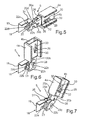
- FIG. 3 In the illustration according to Fig. 3 is the hinge 5 as shown in FIG Fig. 2 shown in a first end position, in which the door 4 is in the fully closed state.
- the hinge blade 20 is oriented vertically with its longitudinal axis G, whereas the housing 19 and thus also the hinge base body 18 is still oriented horizontally with its longitudinal axis H oriented.
- Fig. 3 As in this view according to Fig. 3 can be seen, in the two plate-like parts 20a and 20b each have a slot 27 and 28 ( Fig. 5 ) educated.
- the elongated holes 27 and 28 are guides in which the bolt 25 is guided.
- the actuator or the actuator 24 can therefore only move in a linear linear movement relative to the hinge blade 20 forward and backward.
- Fig. 3 is shown in this first end position of the hinge 5 of the fully and thus maximum extended state of the actuator 24.
- a front end 24a of the actuator 24 is in contact with another pin 29 which is guided in a slot 30 of the door profile 4a.
- the bolt 29 is associated with a coupling unit, by means of which the movement of the door handle 17 depending on a movement of the hinge 5 and / or the hinge 6 is effected.
- Fig. 4 is shown in a further perspective sectional view of the hinge 5 in an intermediate position.
- this intermediate position a locking of the position of the door 4 is ensured.
- the holding element 26 of his in Fig. 2 and Fig. 3 shown first end position is folded up and is posted on a stop 31 on the housing 19.
- the door 4 can thus no longer automatically and automatically go into this fully closed position in this intermediate position.
- this intermediate position of the hinge 5 and thus also the door 4 the door 4 can be removed from the domestic appliance housing 7.
- Fig. 5 is shown in a perspective view, the hinge 5, wherein also a partial section is shown here.
- the transmission element 22 and the hinge blade 20 and the holding member 26 are shown in their entirety.
- the hinge blade 20 and the actuator 24 extend into the interior of a hollow part 4b of the door profile 4a, wherein this hollow part 4b is formed as a shaft in which the bolt 29 is secured over pins 32 out.
- the split pins 32 also secure a cable 33, which is associated with a cable pulling device.
- the cable pulling device is connected to the door handle 17, so that depending on the movement of the bolt 29, initiated by the actuator 24, the cable pulling device is actuated and thereby the door handle 17 is actuated.
- Fig. 6 is a perspective view and otherwise in a further sectional view, the hinge 5 according to the position in Fig. 3 shown. Accordingly, in Fig. 7 another perspective view of the hinge 5 according to a position in Fig. 4 shown in FIG Fig. 7 a different cutting plane than in Fig. 4 is trained. With respect to the plate-like brackets 22a and 22b of the transmission element 22 designed as a double bracket, these have bulges 22c at their lower edges, through which the bolt 21 extends.
- the two plate-like brackets 22a and 22b are spaced apart such that an intermediate space 22d is formed.
- the rear ends of the hinge blade 20 extend with respect to the two plate-like parts 20a and 20b.
- a free space 20d is formed, in which the actuator 24 extends.
- the components transmission element 22, hinge blade 20 and actuator 24 are thus arranged nested, so that an extremely compact and with regard to the multiple relative mobility of the components to each other robust and highly flexible system is designed.
- Fig. 8 is in a further perspective sectional view of a position of the hinge 5 according to Fig. 2 and Fig. 5 shown.
- a tension spring 34 is arranged in the housing 19. This is connected with its front end 35 with a coupling element 36 which is connected to the hinge blade 20.
- the coupling element 36 is designed as a length-stable and rigid component, which is coupled in particular with a bolt not shown in detail, so that the relative rotation between the hinge blade 20 and the coupling element 36 is given.
- the tension spring 34 With a rear end 37, the tension spring 34 is connected to an anchor member 38 fixedly mounted in the housing 19 and suspended therein. The tension spring 34 is maximally pulled apart in the second end position of the hinge 5 and thus in the fully open position.
- the coupling element 26 also extends into the free space 20d.
- Fig. 9 is a perspective sectional view of the hinge 5 as shown in FIG Fig. 8 shown with the corresponding components, here a position of the hinge 5 according to the Fig. 3 and Fig. 6 is shown.
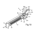
- Fig. 10 is in a perspective sectional view of the hinge with the components in FIGS. 8 and 9 shown here, wherein here the hinge position according to Fig. 4 and Fig. 7 is shown, which represents an intermediate position.
- the folded-back state of the holding element 26 can be seen, which bears against the stop 31.
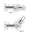
- Fig. 11 is in a side view of the sectional view in Fig. 8 the hinge 5 is shown.
- a door profile 4a arranged, biased by a spring 39, carriage 40 is shown. This is in direct contact with the actuator 24.
- the carriage 40 is linearly pushed back and forth along the arrow P1, which moves due to this movement of the door handle 17.
- the biased spring 39 of the carriage 40 is always held in contact with the actuator 24 and then automatically turn into the in Fig. 11 shown basic position, if he was initiated by the actuator 24, to the right, outward or forward pushed.
- Fig. 12 is a sectional view of the hinge 5 according to the embodiment in Fig. 10 shown in the intermediate position, in addition here also in the door profile 4a, the tension spring 39 and the carriage 40 are shown.
- a bolt 41 which represents the rotatable connection between the coupling element 36 and the hinge blade 20.
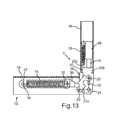
- Fig. 13 is shown in a side sectional view, the hinge 5 in the first end position, this analogous to the representation in Fig. 9 given is.
- the components of the spring 39 and the carriage 40 are also shown.
- the carriage 40 is pushed away a maximum of the hinge blade 20, in which case the actuator 24 is pushed out beyond the front side 20c of the hinge blade 20 maximum.
- the vertical standing on the dashed line between the cross-sectional centers of the bolt 21 and 23 on the one hand and the bolts 21 and 25 on the other hand can be seen here.
- Fig. 14 is in a further perspective sectional view of the hinge 5 as shown in FIG Fig. 13 shown. It can be seen here that the bolt 29 is connected to the carriage 40 or is arranged thereon. The bolt 29 has a cable receptacle 29 a, around which the cable 33 can be guided around.
- the front end 24a of the actuator 24 abuts against the rear side of the carriage 40 and actuates or displaces it accordingly.
- a direct coupling is provided, as for example in the Fig. 2 to Fig. 4 is shown. In such an embodiment, the actuator 24 would then be guided through a hole in the carriage 40 in this and are in direct contact with its front side 24a with the bolt 29 are.
- Fig. 15 is in a further perspective view of the arrangement comprising the hinge 5, as they are in Fig. 14 is shown in the second end position and thus the fully open position shown.
- Fig. 16 is the arrangement according to Fig. 14 and Fig. 15 represented with the components shown there in the intermediate position of the hinge 5.
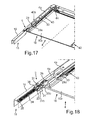
- Fig. 17 is a perspective view of the door 4 on its back and thus the cooking chamber 2 facing side shown.
- an arrangement 42 a and 42 b is formed on opposite sides in each case.
- FIG. 18 is an enlarged partial section of the illustration in Fig. 17 shown, where some parts are shown transparent.
- FIGS. 17 and 18 is the fully opened state of the door 4 and thus the second end position of the hinge 5 is shown.
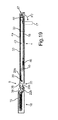
- Fig. 19 is a sectional view through the door 4 shown. It can be seen that the cable 33 is connected on one side to the guide bolt 29, in particular the part 29a, is deflected by a deflection roller or deflection mechanism 44 on the door handle 17 and is connected to a second end-side area with a connection 45. This is in turn coupled via a further spring 46. In this fully open position of the door 4, the handle 17 can be taken from the front.
- the door handle 17 is automatically pivoted forward via the cable pull device 43 according to the arrow illustration P2 so that it then follows the schematically indicated dashed position in the closed position of the door is vertically forward and also in turn can be easily used accordingly.
Landscapes
- Engineering & Computer Science (AREA)
- Mechanical Engineering (AREA)
- Hinges (AREA)
- Refrigerator Housings (AREA)
- Electric Ovens (AREA)
- Power-Operated Mechanisms For Wings (AREA)
Priority Applications (1)
| Application Number | Priority Date | Filing Date | Title |
|---|---|---|---|
| PL12172961T PL2540940T3 (pl) | 2011-07-01 | 2012-06-21 | Zawias do drzwi urządzenia domowego, drzwi z tego rodzaju zawiasem i urządzenie domowe z odpowiednim zawiasem i sposób uruchamiania uchwytu drzwiowego |
Applications Claiming Priority (1)
| Application Number | Priority Date | Filing Date | Title |
|---|---|---|---|
| DE102011078535A DE102011078535A1 (de) | 2011-07-01 | 2011-07-01 | Scharnier für eine Tür eines Hausgeräts, Tür mit einem derartigen Scharnier sowie Hausgerät mit einem entsprechenden Scharnier als auch Verfahren zum Betätigen eines Türgriffs einer Tür |
Publications (3)
| Publication Number | Publication Date |
|---|---|
| EP2540940A2 true EP2540940A2 (fr) | 2013-01-02 |
| EP2540940A3 EP2540940A3 (fr) | 2017-12-27 |
| EP2540940B1 EP2540940B1 (fr) | 2019-03-13 |
Family
ID=46319041
Family Applications (1)
| Application Number | Title | Priority Date | Filing Date |
|---|---|---|---|
| EP12172961.0A Active EP2540940B1 (fr) | 2011-07-01 | 2012-06-21 | Articulation pour une porte d'un appareil ménager, porte avec une telle articulation et appareil ménager doté d'une articulation correspondante ainsi qu'un procédé d'actionnement d'une poignée de porte |
Country Status (5)
| Country | Link |
|---|---|
| EP (1) | EP2540940B1 (fr) |
| DE (1) | DE102011078535A1 (fr) |
| ES (1) | ES2720849T3 (fr) |
| PL (1) | PL2540940T3 (fr) |
| TR (1) | TR201904474T4 (fr) |
Cited By (3)
| Publication number | Priority date | Publication date | Assignee | Title |
|---|---|---|---|---|
| EP2740871B1 (fr) * | 2012-12-04 | 2020-08-12 | BSH Hausgeräte GmbH | Dispositif destiné à un appareil ménager comprenant une charnière et un dispositif de couplage et appareil ménager doté d'un tel dispositif |
| CN116348653A (zh) * | 2020-10-12 | 2023-06-27 | 特纳有限公司 | 用于家用器具的门铰链 |
| CN116753659A (zh) * | 2023-05-29 | 2023-09-15 | 海信冰箱有限公司 | 冰箱 |
Families Citing this family (5)
| Publication number | Priority date | Publication date | Assignee | Title |
|---|---|---|---|---|
| DE102015226009A1 (de) * | 2015-12-18 | 2017-06-22 | BSH Hausgeräte GmbH | Gargerät mit einer Türöffnungsvorrichtung zum automatischen Verbringen einer Tür in eine Zwischenstellung sowie Verfahren zum Öffnen einer Tür eines Gargeräts |
| DE102017207980A1 (de) | 2017-05-11 | 2018-11-15 | BSH Hausgeräte GmbH | Gargerät mit einer Seilzugvorrichtung zum automatischen Schwenken einer Tür |
| DE102017213095A1 (de) | 2017-07-28 | 2019-01-31 | BSH Hausgeräte GmbH | Gargerät mit versenkbarer Tür, die eine spezifische Haltefeder für eine Lagerbuchse aufweist |
| DE102018214393A1 (de) * | 2018-08-27 | 2020-02-27 | BSH Hausgeräte GmbH | Haushalts-Mikrowellengerät |
| CN109386196A (zh) * | 2018-12-21 | 2019-02-26 | 合肥口福科技有限公司 | 门回拉铰链装置 |
Citations (1)
| Publication number | Priority date | Publication date | Assignee | Title |
|---|---|---|---|---|
| DE19923994A1 (de) | 1999-05-26 | 2000-11-30 | Bsh Bosch Siemens Hausgeraete | Hausgerät-Scharniervorrichtung |
Family Cites Families (4)
| Publication number | Priority date | Publication date | Assignee | Title |
|---|---|---|---|---|
| IT1235584B (it) * | 1989-09-06 | 1992-09-11 | C M I Cerniere Meccaniche Indu | Cerniera per l'apertura e chiusura semiautomatica di portelli particolarmente indicata per portelli frontali ad articolazione ad asse orizzontale di lavastoviglie |
| DE10208494B4 (de) * | 2002-02-27 | 2008-04-17 | BSH Bosch und Siemens Hausgeräte GmbH | Haushaltsgerätetür und Haushaltsgerät |
| ITPD20060034A1 (it) * | 2006-02-02 | 2007-08-03 | Zanovello Srl | Cerniera per porte di forno o simili |
| DE102007041909A1 (de) * | 2007-09-04 | 2009-03-05 | BSH Bosch und Siemens Hausgeräte GmbH | Scharniergehäuse für eine Hausgerätetür |
-
2011
- 2011-07-01 DE DE102011078535A patent/DE102011078535A1/de not_active Withdrawn
-
2012
- 2012-06-21 PL PL12172961T patent/PL2540940T3/pl unknown
- 2012-06-21 EP EP12172961.0A patent/EP2540940B1/fr active Active
- 2012-06-21 ES ES12172961T patent/ES2720849T3/es active Active
- 2012-06-21 TR TR2019/04474T patent/TR201904474T4/tr unknown
Patent Citations (1)
| Publication number | Priority date | Publication date | Assignee | Title |
|---|---|---|---|---|
| DE19923994A1 (de) | 1999-05-26 | 2000-11-30 | Bsh Bosch Siemens Hausgeraete | Hausgerät-Scharniervorrichtung |
Cited By (3)
| Publication number | Priority date | Publication date | Assignee | Title |
|---|---|---|---|---|
| EP2740871B1 (fr) * | 2012-12-04 | 2020-08-12 | BSH Hausgeräte GmbH | Dispositif destiné à un appareil ménager comprenant une charnière et un dispositif de couplage et appareil ménager doté d'un tel dispositif |
| CN116348653A (zh) * | 2020-10-12 | 2023-06-27 | 特纳有限公司 | 用于家用器具的门铰链 |
| CN116753659A (zh) * | 2023-05-29 | 2023-09-15 | 海信冰箱有限公司 | 冰箱 |
Also Published As
| Publication number | Publication date |
|---|---|
| EP2540940A3 (fr) | 2017-12-27 |
| DE102011078535A1 (de) | 2013-01-03 |
| ES2720849T3 (es) | 2019-07-25 |
| PL2540940T3 (pl) | 2019-09-30 |
| EP2540940B1 (fr) | 2019-03-13 |
| TR201904474T4 (tr) | 2019-04-22 |
Similar Documents
| Publication | Publication Date | Title |
|---|---|---|
| EP2540940B1 (fr) | Articulation pour une porte d'un appareil ménager, porte avec une telle articulation et appareil ménager doté d'une articulation correspondante ainsi qu'un procédé d'actionnement d'une poignée de porte | |
| EP2191088B2 (fr) | Charnière de porte d' appareil ménager | |
| EP2250929B1 (fr) | Elément d'armoire doté d'un élément de sortie rétractable | |
| EP3622223B1 (fr) | Appareil de cuisson équipé d'un dispositif de traction par câble pour le pivotement automatique d'une porte | |
| EP2574712A1 (fr) | Appareil ménager avec une cavité et une porte de fermeture de la cavité et procédé d'actionnement d'une porte d'un appareil ménager | |
| EP2362050A2 (fr) | Dispositif de charnière, appareil ménager doté d'une porte et procédé de rééquipement d'un amortisseur | |
| EP2992156B1 (fr) | Système de guidage d'une porte coulissante, porte coulissante et meuble | |
| WO2012038339A1 (fr) | Dispositif de rentrée automatique pour un élément de meuble mobile | |
| DE102019213486A1 (de) | Gargerät mit spezifischer Türöffnungsvorrichtung zum automatischen Schwenken einer versenkbaren Tür des Gargeräts, sowie Verfahren | |
| EP2746703B1 (fr) | Porte d'appareil frigorifique ménager avec poignée repositionnable sans démontage, appareil frigorifique ménager et procédé de positionnement d'une poignée | |
| DE102016215651A1 (de) | Versenkbare Tür mit einem schwenkbaren plattenartigen Griffteil sowie Haushaltsgerät | |
| EP3658824B1 (fr) | Appareil de cuisson muni d'une porte escamotable qui présente un ressort de retenue spécifique pour un coussinet de palier | |
| EP2581666B1 (fr) | Porte pour un appareil ménager, appareil ménager équipé d'une porte et procédé de déplacement de la poignée de porte d'un appareil ménager | |
| EP2741015B1 (fr) | Porte pour un appareil ménager comprenant une partie de préhension de type plaque et un système d'ouverture de la partie de préhension, appareil ménager doté d'une telle porte et procédé d'ouverture d'une porte d'un appareil ménager | |
| DE102009002419B4 (de) | Tür mit mindestens einem Betätigungselement und mindestens einem Riegel | |
| EP2189726A2 (fr) | Poignée escamotable pour une porte d'un appareil ménager et porte d'un appareil ménager doté d'une telle poignée | |
| WO2016020344A1 (fr) | Porte pour un appareil ménager, appareil ménager comprenant une porte | |
| EP2884188A1 (fr) | Appareil ménager doté d'une porte escamotable dans un espace de rangement et d'un axe de rotation déplaçable d'une unité de stockage et procédé d'ouverture et de fermeture d'une telle porte | |
| DE10009633A1 (de) | Türdrücker | |
| EP2930436B1 (fr) | Appareil ménager doté d'une porte escamotable et procédé d'ouverture et de fermeture d'une porte d'appareil ménager | |
| EP2884189B1 (fr) | Appareil ménager doté d'une porte pouvant être entrée dans un espace de rangement et procédé d'ouverture et de fermeture d'une porte d'un appareil ménager | |
| DE102010023526B4 (de) | Gerätegehäuse mit einer Tür | |
| DE102012222160A1 (de) | Vorrichtung für ein Haushaltsgerät mit einem Scharnier und einer Koppeleinrichtung sowie Haushaltsgerät mit einer derartigen Vorrichtung | |
| DE102022203509A1 (de) | Haushaltsgerät mit spezifischem Kupplungs-Schlittensystem für eine versenkbare Tür, sowie Verfahren | |
| WO2023194082A1 (fr) | Appareil ménager équipé d'un système d'entraînement spécifique pour l'actionnement de la porte, et procédé |
Legal Events
| Date | Code | Title | Description |
|---|---|---|---|
| PUAI | Public reference made under article 153(3) epc to a published international application that has entered the european phase |
Free format text: ORIGINAL CODE: 0009012 |
|
| AK | Designated contracting states |
Kind code of ref document: A2 Designated state(s): AL AT BE BG CH CY CZ DE DK EE ES FI FR GB GR HR HU IE IS IT LI LT LU LV MC MK MT NL NO PL PT RO RS SE SI SK SM TR |
|
| AX | Request for extension of the european patent |
Extension state: BA ME |
|
| RAP1 | Party data changed (applicant data changed or rights of an application transferred) |
Owner name: BSH HAUSGERAETE GMBH |
|
| PUAL | Search report despatched |
Free format text: ORIGINAL CODE: 0009013 |
|
| AK | Designated contracting states |
Kind code of ref document: A3 Designated state(s): AL AT BE BG CH CY CZ DE DK EE ES FI FR GB GR HR HU IE IS IT LI LT LU LV MC MK MT NL NO PL PT RO RS SE SI SK SM TR |
|
| AX | Request for extension of the european patent |
Extension state: BA ME |
|
| RIC1 | Information provided on ipc code assigned before grant |
Ipc: E05F 5/00 20170101ALN20171123BHEP Ipc: E05F 1/12 20060101ALI20171123BHEP Ipc: E05D 3/02 20060101AFI20171123BHEP Ipc: E05D 3/18 20060101ALN20171123BHEP |
|
| STAA | Information on the status of an ep patent application or granted ep patent |
Free format text: STATUS: REQUEST FOR EXAMINATION WAS MADE |
|
| 17P | Request for examination filed |
Effective date: 20180627 |
|
| RBV | Designated contracting states (corrected) |
Designated state(s): AL AT BE BG CH CY CZ DE DK EE ES FI FR GB GR HR HU IE IS IT LI LT LU LV MC MK MT NL NO PL PT RO RS SE SI SK SM TR |
|
| RIC1 | Information provided on ipc code assigned before grant |
Ipc: E05F 1/12 20060101ALI20180823BHEP Ipc: E05D 3/02 20060101AFI20180823BHEP Ipc: E05D 3/18 20060101ALN20180823BHEP Ipc: E05F 5/00 20060101ALN20180823BHEP |
|
| GRAJ | Information related to disapproval of communication of intention to grant by the applicant or resumption of examination proceedings by the epo deleted |
Free format text: ORIGINAL CODE: EPIDOSDIGR1 |
|
| GRAP | Despatch of communication of intention to grant a patent |
Free format text: ORIGINAL CODE: EPIDOSNIGR1 |
|
| GRAP | Despatch of communication of intention to grant a patent |
Free format text: ORIGINAL CODE: EPIDOSNIGR1 |
|
| STAA | Information on the status of an ep patent application or granted ep patent |
Free format text: STATUS: GRANT OF PATENT IS INTENDED |
|
| RIC1 | Information provided on ipc code assigned before grant |
Ipc: E05F 1/12 20060101ALI20181003BHEP Ipc: E05D 3/02 20060101AFI20181003BHEP Ipc: E05F 5/00 20060101ALN20181003BHEP Ipc: E05D 3/18 20060101ALN20181003BHEP |
|
| INTG | Intention to grant announced |
Effective date: 20181016 |
|
| GRAS | Grant fee paid |
Free format text: ORIGINAL CODE: EPIDOSNIGR3 |
|
| GRAA | (expected) grant |
Free format text: ORIGINAL CODE: 0009210 |
|
| STAA | Information on the status of an ep patent application or granted ep patent |
Free format text: STATUS: THE PATENT HAS BEEN GRANTED |
|
| AK | Designated contracting states |
Kind code of ref document: B1 Designated state(s): AL AT BE BG CH CY CZ DE DK EE ES FI FR GB GR HR HU IE IS IT LI LT LU LV MC MK MT NL NO PL PT RO RS SE SI SK SM TR |
|
| REG | Reference to a national code |
Ref country code: GB Ref legal event code: FG4D Free format text: NOT ENGLISH |
|
| REG | Reference to a national code |
Ref country code: CH Ref legal event code: EP Ref country code: AT Ref legal event code: REF Ref document number: 1107875 Country of ref document: AT Kind code of ref document: T Effective date: 20190315 |
|
| REG | Reference to a national code |
Ref country code: IE Ref legal event code: FG4D Free format text: LANGUAGE OF EP DOCUMENT: GERMAN |
|
| REG | Reference to a national code |
Ref country code: DE Ref legal event code: R096 Ref document number: 502012014424 Country of ref document: DE |
|
| REG | Reference to a national code |
Ref country code: NL Ref legal event code: MP Effective date: 20190313 |
|
| REG | Reference to a national code |
Ref country code: ES Ref legal event code: FG2A Ref document number: 2720849 Country of ref document: ES Kind code of ref document: T3 Effective date: 20190725 Ref country code: LT Ref legal event code: MG4D |
|
| PG25 | Lapsed in a contracting state [announced via postgrant information from national office to epo] |
Ref country code: FI Free format text: LAPSE BECAUSE OF FAILURE TO SUBMIT A TRANSLATION OF THE DESCRIPTION OR TO PAY THE FEE WITHIN THE PRESCRIBED TIME-LIMIT Effective date: 20190313 Ref country code: NO Free format text: LAPSE BECAUSE OF FAILURE TO SUBMIT A TRANSLATION OF THE DESCRIPTION OR TO PAY THE FEE WITHIN THE PRESCRIBED TIME-LIMIT Effective date: 20190613 Ref country code: SE Free format text: LAPSE BECAUSE OF FAILURE TO SUBMIT A TRANSLATION OF THE DESCRIPTION OR TO PAY THE FEE WITHIN THE PRESCRIBED TIME-LIMIT Effective date: 20190313 Ref country code: LT Free format text: LAPSE BECAUSE OF FAILURE TO SUBMIT A TRANSLATION OF THE DESCRIPTION OR TO PAY THE FEE WITHIN THE PRESCRIBED TIME-LIMIT Effective date: 20190313 |
|
| PG25 | Lapsed in a contracting state [announced via postgrant information from national office to epo] |
Ref country code: HR Free format text: LAPSE BECAUSE OF FAILURE TO SUBMIT A TRANSLATION OF THE DESCRIPTION OR TO PAY THE FEE WITHIN THE PRESCRIBED TIME-LIMIT Effective date: 20190313 Ref country code: GR Free format text: LAPSE BECAUSE OF FAILURE TO SUBMIT A TRANSLATION OF THE DESCRIPTION OR TO PAY THE FEE WITHIN THE PRESCRIBED TIME-LIMIT Effective date: 20190614 Ref country code: NL Free format text: LAPSE BECAUSE OF FAILURE TO SUBMIT A TRANSLATION OF THE DESCRIPTION OR TO PAY THE FEE WITHIN THE PRESCRIBED TIME-LIMIT Effective date: 20190313 Ref country code: LV Free format text: LAPSE BECAUSE OF FAILURE TO SUBMIT A TRANSLATION OF THE DESCRIPTION OR TO PAY THE FEE WITHIN THE PRESCRIBED TIME-LIMIT Effective date: 20190313 Ref country code: BG Free format text: LAPSE BECAUSE OF FAILURE TO SUBMIT A TRANSLATION OF THE DESCRIPTION OR TO PAY THE FEE WITHIN THE PRESCRIBED TIME-LIMIT Effective date: 20190613 Ref country code: RS Free format text: LAPSE BECAUSE OF FAILURE TO SUBMIT A TRANSLATION OF THE DESCRIPTION OR TO PAY THE FEE WITHIN THE PRESCRIBED TIME-LIMIT Effective date: 20190313 |
|
| PG25 | Lapsed in a contracting state [announced via postgrant information from national office to epo] |
Ref country code: SK Free format text: LAPSE BECAUSE OF FAILURE TO SUBMIT A TRANSLATION OF THE DESCRIPTION OR TO PAY THE FEE WITHIN THE PRESCRIBED TIME-LIMIT Effective date: 20190313 Ref country code: RO Free format text: LAPSE BECAUSE OF FAILURE TO SUBMIT A TRANSLATION OF THE DESCRIPTION OR TO PAY THE FEE WITHIN THE PRESCRIBED TIME-LIMIT Effective date: 20190313 Ref country code: CZ Free format text: LAPSE BECAUSE OF FAILURE TO SUBMIT A TRANSLATION OF THE DESCRIPTION OR TO PAY THE FEE WITHIN THE PRESCRIBED TIME-LIMIT Effective date: 20190313 Ref country code: IT Free format text: LAPSE BECAUSE OF FAILURE TO SUBMIT A TRANSLATION OF THE DESCRIPTION OR TO PAY THE FEE WITHIN THE PRESCRIBED TIME-LIMIT Effective date: 20190313 Ref country code: EE Free format text: LAPSE BECAUSE OF FAILURE TO SUBMIT A TRANSLATION OF THE DESCRIPTION OR TO PAY THE FEE WITHIN THE PRESCRIBED TIME-LIMIT Effective date: 20190313 Ref country code: PT Free format text: LAPSE BECAUSE OF FAILURE TO SUBMIT A TRANSLATION OF THE DESCRIPTION OR TO PAY THE FEE WITHIN THE PRESCRIBED TIME-LIMIT Effective date: 20190713 Ref country code: AL Free format text: LAPSE BECAUSE OF FAILURE TO SUBMIT A TRANSLATION OF THE DESCRIPTION OR TO PAY THE FEE WITHIN THE PRESCRIBED TIME-LIMIT Effective date: 20190313 |
|
| PG25 | Lapsed in a contracting state [announced via postgrant information from national office to epo] |
Ref country code: SM Free format text: LAPSE BECAUSE OF FAILURE TO SUBMIT A TRANSLATION OF THE DESCRIPTION OR TO PAY THE FEE WITHIN THE PRESCRIBED TIME-LIMIT Effective date: 20190313 |
|
| REG | Reference to a national code |
Ref country code: DE Ref legal event code: R097 Ref document number: 502012014424 Country of ref document: DE |
|
| PG25 | Lapsed in a contracting state [announced via postgrant information from national office to epo] |
Ref country code: IS Free format text: LAPSE BECAUSE OF FAILURE TO SUBMIT A TRANSLATION OF THE DESCRIPTION OR TO PAY THE FEE WITHIN THE PRESCRIBED TIME-LIMIT Effective date: 20190713 |
|
| PLBE | No opposition filed within time limit |
Free format text: ORIGINAL CODE: 0009261 |
|
| STAA | Information on the status of an ep patent application or granted ep patent |
Free format text: STATUS: NO OPPOSITION FILED WITHIN TIME LIMIT |
|
| PG25 | Lapsed in a contracting state [announced via postgrant information from national office to epo] |
Ref country code: DK Free format text: LAPSE BECAUSE OF FAILURE TO SUBMIT A TRANSLATION OF THE DESCRIPTION OR TO PAY THE FEE WITHIN THE PRESCRIBED TIME-LIMIT Effective date: 20190313 Ref country code: MC Free format text: LAPSE BECAUSE OF FAILURE TO SUBMIT A TRANSLATION OF THE DESCRIPTION OR TO PAY THE FEE WITHIN THE PRESCRIBED TIME-LIMIT Effective date: 20190313 |
|
| REG | Reference to a national code |
Ref country code: CH Ref legal event code: PL |
|
| 26N | No opposition filed |
Effective date: 20191216 |
|
| PG25 | Lapsed in a contracting state [announced via postgrant information from national office to epo] |
Ref country code: SI Free format text: LAPSE BECAUSE OF FAILURE TO SUBMIT A TRANSLATION OF THE DESCRIPTION OR TO PAY THE FEE WITHIN THE PRESCRIBED TIME-LIMIT Effective date: 20190313 |
|
| REG | Reference to a national code |
Ref country code: BE Ref legal event code: MM Effective date: 20190630 |
|
| PG25 | Lapsed in a contracting state [announced via postgrant information from national office to epo] |
Ref country code: IE Free format text: LAPSE BECAUSE OF NON-PAYMENT OF DUE FEES Effective date: 20190621 |
|
| PG25 | Lapsed in a contracting state [announced via postgrant information from national office to epo] |
Ref country code: BE Free format text: LAPSE BECAUSE OF NON-PAYMENT OF DUE FEES Effective date: 20190630 Ref country code: LI Free format text: LAPSE BECAUSE OF NON-PAYMENT OF DUE FEES Effective date: 20190630 Ref country code: LU Free format text: LAPSE BECAUSE OF NON-PAYMENT OF DUE FEES Effective date: 20190621 Ref country code: CH Free format text: LAPSE BECAUSE OF NON-PAYMENT OF DUE FEES Effective date: 20190630 |
|
| REG | Reference to a national code |
Ref country code: AT Ref legal event code: MM01 Ref document number: 1107875 Country of ref document: AT Kind code of ref document: T Effective date: 20190621 |
|
| PG25 | Lapsed in a contracting state [announced via postgrant information from national office to epo] |
Ref country code: AT Free format text: LAPSE BECAUSE OF NON-PAYMENT OF DUE FEES Effective date: 20190621 |
|
| PG25 | Lapsed in a contracting state [announced via postgrant information from national office to epo] |
Ref country code: CY Free format text: LAPSE BECAUSE OF FAILURE TO SUBMIT A TRANSLATION OF THE DESCRIPTION OR TO PAY THE FEE WITHIN THE PRESCRIBED TIME-LIMIT Effective date: 20190313 |
|
| PG25 | Lapsed in a contracting state [announced via postgrant information from national office to epo] |
Ref country code: MT Free format text: LAPSE BECAUSE OF FAILURE TO SUBMIT A TRANSLATION OF THE DESCRIPTION OR TO PAY THE FEE WITHIN THE PRESCRIBED TIME-LIMIT Effective date: 20190313 Ref country code: HU Free format text: LAPSE BECAUSE OF FAILURE TO SUBMIT A TRANSLATION OF THE DESCRIPTION OR TO PAY THE FEE WITHIN THE PRESCRIBED TIME-LIMIT; INVALID AB INITIO Effective date: 20120621 |
|
| PG25 | Lapsed in a contracting state [announced via postgrant information from national office to epo] |
Ref country code: MK Free format text: LAPSE BECAUSE OF FAILURE TO SUBMIT A TRANSLATION OF THE DESCRIPTION OR TO PAY THE FEE WITHIN THE PRESCRIBED TIME-LIMIT Effective date: 20190313 |
|
| REG | Reference to a national code |
Ref country code: DE Ref legal event code: R084 Ref document number: 502012014424 Country of ref document: DE |
|
| P01 | Opt-out of the competence of the unified patent court (upc) registered |
Effective date: 20230504 |
|
| REG | Reference to a national code |
Ref country code: ES Ref legal event code: GC2A Effective date: 20240830 |
|
| PGFP | Annual fee paid to national office [announced via postgrant information from national office to epo] |
Ref country code: PL Payment date: 20250610 Year of fee payment: 14 Ref country code: DE Payment date: 20250630 Year of fee payment: 14 |
|
| PGFP | Annual fee paid to national office [announced via postgrant information from national office to epo] |
Ref country code: GB Payment date: 20250620 Year of fee payment: 14 |
|
| PGFP | Annual fee paid to national office [announced via postgrant information from national office to epo] |
Ref country code: FR Payment date: 20250618 Year of fee payment: 14 |
|
| PGFP | Annual fee paid to national office [announced via postgrant information from national office to epo] |
Ref country code: TR Payment date: 20250618 Year of fee payment: 14 |
|
| PGFP | Annual fee paid to national office [announced via postgrant information from national office to epo] |
Ref country code: ES Payment date: 20250718 Year of fee payment: 14 |