EP2541709A2 - Attache de câble à longueur réglable pouvant éliminer le gaspillage de celle-ci - Google Patents
Attache de câble à longueur réglable pouvant éliminer le gaspillage de celle-ci Download PDFInfo
- Publication number
- EP2541709A2 EP2541709A2 EP11747601A EP11747601A EP2541709A2 EP 2541709 A2 EP2541709 A2 EP 2541709A2 EP 11747601 A EP11747601 A EP 11747601A EP 11747601 A EP11747601 A EP 11747601A EP 2541709 A2 EP2541709 A2 EP 2541709A2
- Authority
- EP
- European Patent Office
- Prior art keywords
- engaging head
- head part
- belt
- belt part
- inlet
- Prior art date
- Legal status (The legal status is an assumption and is not a legal conclusion. Google has not performed a legal analysis and makes no representation as to the accuracy of the status listed.)
- Withdrawn
Links
Images




Classifications
-
- B—PERFORMING OPERATIONS; TRANSPORTING
- B65—CONVEYING; PACKING; STORING; HANDLING THIN OR FILAMENTARY MATERIAL
- B65D—CONTAINERS FOR STORAGE OR TRANSPORT OF ARTICLES OR MATERIALS, e.g. BAGS, BARRELS, BOTTLES, BOXES, CANS, CARTONS, CRATES, DRUMS, JARS, TANKS, HOPPERS, FORWARDING CONTAINERS; ACCESSORIES, CLOSURES, OR FITTINGS THEREFOR; PACKAGING ELEMENTS; PACKAGES
- B65D63/00—Flexible elongated elements, e.g. straps, for bundling or supporting articles
- B65D63/10—Non-metallic straps, tapes, or bands; Filamentary elements, e.g. strings, threads or wires; Joints between ends thereof
- B65D63/1018—Joints produced by application of integral securing members, e.g. buckles, wedges, tongue and slot, locking head and teeth or the like
- B65D63/1027—Joints produced by application of integral securing members, e.g. buckles, wedges, tongue and slot, locking head and teeth or the like the integral securing member being formed as a female and male locking member, e.g. locking head and locking teeth, or the like
- B65D63/1063—Joints produced by application of integral securing members, e.g. buckles, wedges, tongue and slot, locking head and teeth or the like the integral securing member being formed as a female and male locking member, e.g. locking head and locking teeth, or the like the female locking member being provided with at least one plastic barb
-
- H—ELECTRICITY
- H02—GENERATION; CONVERSION OR DISTRIBUTION OF ELECTRIC POWER
- H02G—INSTALLATION OF ELECTRIC CABLES OR LINES, OR OF COMBINED OPTICAL AND ELECTRIC CABLES OR LINES
- H02G3/00—Installations of electric cables or lines or protective tubing therefor in or on buildings, equivalent structures or vehicles
- H02G3/26—Installations of cables, lines, or separate protective tubing therefor directly on or in walls, ceilings, or floors
-
- F—MECHANICAL ENGINEERING; LIGHTING; HEATING; WEAPONS; BLASTING
- F16—ENGINEERING ELEMENTS AND UNITS; GENERAL MEASURES FOR PRODUCING AND MAINTAINING EFFECTIVE FUNCTIONING OF MACHINES OR INSTALLATIONS; THERMAL INSULATION IN GENERAL
- F16L—PIPES; JOINTS OR FITTINGS FOR PIPES; SUPPORTS FOR PIPES, CABLES OR PROTECTIVE TUBING; MEANS FOR THERMAL INSULATION IN GENERAL
- F16L3/00—Supports for pipes, cables or protective tubing, e.g. hangers, holders, clamps, cleats, clips, brackets
- F16L3/08—Supports for pipes, cables or protective tubing, e.g. hangers, holders, clamps, cleats, clips, brackets substantially surrounding the pipe, cable or protective tubing
- F16L3/12—Supports for pipes, cables or protective tubing, e.g. hangers, holders, clamps, cleats, clips, brackets substantially surrounding the pipe, cable or protective tubing comprising a member substantially surrounding the pipe, cable or protective tubing
- F16L3/137—Supports for pipes, cables or protective tubing, e.g. hangers, holders, clamps, cleats, clips, brackets substantially surrounding the pipe, cable or protective tubing comprising a member substantially surrounding the pipe, cable or protective tubing and consisting of a flexible band
-
- F—MECHANICAL ENGINEERING; LIGHTING; HEATING; WEAPONS; BLASTING
- F16—ENGINEERING ELEMENTS AND UNITS; GENERAL MEASURES FOR PRODUCING AND MAINTAINING EFFECTIVE FUNCTIONING OF MACHINES OR INSTALLATIONS; THERMAL INSULATION IN GENERAL
- F16L—PIPES; JOINTS OR FITTINGS FOR PIPES; SUPPORTS FOR PIPES, CABLES OR PROTECTIVE TUBING; MEANS FOR THERMAL INSULATION IN GENERAL
- F16L3/00—Supports for pipes, cables or protective tubing, e.g. hangers, holders, clamps, cleats, clips, brackets
- F16L3/22—Supports for pipes, cables or protective tubing, e.g. hangers, holders, clamps, cleats, clips, brackets specially adapted for supporting a number of parallel pipes at intervals
- F16L3/23—Supports for pipes, cables or protective tubing, e.g. hangers, holders, clamps, cleats, clips, brackets specially adapted for supporting a number of parallel pipes at intervals for a bundle of pipes or a plurality of pipes placed side by side in contact with each other
- F16L3/233—Supports for pipes, cables or protective tubing, e.g. hangers, holders, clamps, cleats, clips, brackets specially adapted for supporting a number of parallel pipes at intervals for a bundle of pipes or a plurality of pipes placed side by side in contact with each other by means of a flexible band
- F16L3/2332—Supports for pipes, cables or protective tubing, e.g. hangers, holders, clamps, cleats, clips, brackets specially adapted for supporting a number of parallel pipes at intervals for a bundle of pipes or a plurality of pipes placed side by side in contact with each other by means of a flexible band having a single plastic locking barb
-
- H—ELECTRICITY
- H02—GENERATION; CONVERSION OR DISTRIBUTION OF ELECTRIC POWER
- H02G—INSTALLATION OF ELECTRIC CABLES OR LINES, OR OF COMBINED OPTICAL AND ELECTRIC CABLES OR LINES
- H02G3/00—Installations of electric cables or lines or protective tubing therefor in or on buildings, equivalent structures or vehicles
- H02G3/30—Installations of cables or lines on walls, floors or ceilings
-
- B—PERFORMING OPERATIONS; TRANSPORTING
- B65—CONVEYING; PACKING; STORING; HANDLING THIN OR FILAMENTARY MATERIAL
- B65D—CONTAINERS FOR STORAGE OR TRANSPORT OF ARTICLES OR MATERIALS, e.g. BAGS, BARRELS, BOTTLES, BOXES, CANS, CARTONS, CRATES, DRUMS, JARS, TANKS, HOPPERS, FORWARDING CONTAINERS; ACCESSORIES, CLOSURES, OR FITTINGS THEREFOR; PACKAGING ELEMENTS; PACKAGES
- B65D2563/00—Flexible elongated elements, e.g. straps for bundling or supporting atricles
- B65D2563/10—Non-metallic straps, tapes or bands; Filamentary elements, e.g. strings, threads, wires; Joints between ends thereof
- B65D2563/101—Details of non-metallic straps, tapes or bands
- B65D2563/103—Details of non-metallic straps, tapes or bands details of the male locking member, e.g. locking teeth on the strap
-
- Y—GENERAL TAGGING OF NEW TECHNOLOGICAL DEVELOPMENTS; GENERAL TAGGING OF CROSS-SECTIONAL TECHNOLOGIES SPANNING OVER SEVERAL SECTIONS OF THE IPC; TECHNICAL SUBJECTS COVERED BY FORMER USPC CROSS-REFERENCE ART COLLECTIONS [XRACs] AND DIGESTS
- Y10—TECHNICAL SUBJECTS COVERED BY FORMER USPC
- Y10T—TECHNICAL SUBJECTS COVERED BY FORMER US CLASSIFICATION
- Y10T24/00—Buckles, buttons, clasps, etc.
- Y10T24/14—Bale and package ties, hose clamps
Definitions
- the present invention relates to a cable tie which makes it possible of cleanly arrange a plurality of cables or wires by tying them, and in particular to a cable tie and a cable tie device which help easily tie cables by adjusting them as much as a user wants irrespective of the kinds of cables to be tied or the thickness of an object.
- a cable tie is widely used at home and in the industry field for the purpose of tying and cleanly arranging a plurality of cables which are randomly put.
- a conventional cable tie is characterized in that a belt part 140 covering cables and an engaging head part 150 fixing the belt part from not slipping are integrally engaged, and various cable tie products such as a short cable tie 120 or a long cable tie 110 are used depending on the thickness of a cable to be tied, which causes a problem when in use, and since the remaining portions of the belt part 130 after it is cut are waste for thereby causing an over consumption of cables. At home or in the industry fields, it is needed to clean the wasted portions after a cable is cleanly arranged and cut.
- the belts are cut as much as needed depending on the surrounding length of each cable fixing and tying a belt part start end portion 327at an engaging head part 202, and the cables are surrounded and tied, and the cut belt end portion 328 is fixed at the engaging head part 202, which construction might help reduce the wasting portions of the belt parts in such a way to cut the belt part as much as a user wants; however since it is possible to complete the tying work after the belt part is cut off in a state of a reel form 370 or a storage tying state before the final engagement, unless the surrounding of the cables to be tied are not accurately measured, the first cut belt part should be inserted into the engaging head part and is continuously pulled in the direction of the insertion for thereby tightening them, and after the tightening work, the unnecessary belt part passes through the engaging head part 202 and is protruded,
- the conventional cable tie causes a lot of cable consumptions, and another conventional art which was aimed at improving the above mentioned problems still has a problem, not completely resolving the problems that cables are over consumed.
- the cable ties are generally manufactured in an extrusion method on a turnkey basis with the material of PVC or other character synthetic resin in consideration with the unit cost while manufacturing the shapes of the engaging head part. In this case, the flexibility of the belt part decreases owing to the natures of the materials, so many inconveniences occur when doing the work of tying cables, and the thickness of the belt part itself increases, so the whole thickness of the tied cables increases after they are arranged.
- a cable tie and a cable tie device which are characterized in that the belt part and the engaging head part are separated, and toothed blades are formed at both sides of the belt part, and the engaging head part configured to effectively use the toothed blades is provided.
- the belt part is first passed through the engaging head part, and the cables to be arranged are surrounded, and the belt part start end portion is fixed at the engaging head part for thereby enhancing workability and preventing over consumptions.
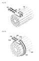
- Figures 1a and 1b are views illustrating conventional cable ties.
- Figures 2a, 2b and 2c are views illustrating a conventional cable tie construction in which a belt part and an engaging part are separated.
- Figure 3 is a view illustrating a cable tie belt part according to a preferred embodiment of the present invention.
- Figure 4 is a view illustrating a cross section of a cable tie belt part according to a preferred embodiment of the present invention.
- Figure 5 is a view illustrating a cable tie engaging head part according to a preferred embodiment of the present invention.
- Figure 6 is a view illustrating a use state of a cable tie according to a preferred embodiment of the present invention.
- Figure 7 is a view illustrating a use stage of a cable tie according to a preferred embodiment of the present invention.
- Figure 8 is a view illustrating a cable tie engaging head part according to another preferred embodiment of the present invention.
- Figure 9 is a view illustrating a construction that a cable tie engaging head part is partially cut along a curved surface according to further another preferred embodiment of the present invention.
- Figure 10 is a view illustrating a use state of a cable tie according to further another preferred embodiment of the present invention.
- Figure 11 is a view illustrating a use stage of a cable tie according to further another preferred embodiment of the present invention.
- Figure 6 is a perspective view before and after a belt part 310 is inserted into an end inlet 331 of an engaging head part 320 after cables which are needed to be arranged are gathered together and are tied using a cable tie belt part 310 and an engaging head part 320 according to a preferred embodiment of the present invention.
- the start inlet 329 and the end inlet 331 of the engaging head part 320 according to a preferred embodiment of the present invention are positioned on the facing surfaces in the engaging head part 320.
- the belt part 310 is fixedly inserted into the engaging head part 320 via the end inlet 331 after it surrounds the cables to be tied after it passes through the start inlet 329 of the engaging head part 320.
- the belt part 310 passing through the engaging head part 320 remains in a state that the toothed blades are engaged with each other at the folded surfaces with the contacting belt part start end portion 327, and the belt part 310 no longer passes through the engaging head part 320 via the start inlet 329; however since it is possible to pull and take out the belt part 310, which passed through the engaging head part 320, in the opposite direction that the start inlet 329 is passed, when the belt part 310 surrounding the cables, which are needed to be arranged after they are unwound via the engaging head part 320 long enough in their lengths for easier work is pulled in the opposite direction that the engaging head part start inlet 329 has passed, the cables to be arranged are tightened by means of the belt part 310 surrounding the cables, and after the cables are properly tightened, the belt part 310 fixed at the engaging head part 320 is cut just in front of the start inlet 329, the
- FIG 8 is a 2D view illustrating an engaging head part 420 according to another embodiment of the present invention.
- the engaging head part 420 (hereinafter it is referred to the engaging head part 2) according to another embodiment of the present invention
- the start inlet 329 which is an opening that the belt part 310 first passes through the engaging head part 2 (420)
- the end inlet 331 which is an opening via which the belt part 310 is finally inserted into the final engaging head part 2 (420) are positioned on the same surfaces.
- a separation plate 425 which separates a space where the belt part 310 passes through the start inlet 329 and a space where the belt part 310 is inserted into the end inlet 331 and is accommodated therein.
- the toothed blades 426 are formed at the end portions at the sides of the start inlet 329 and the end inlet 331 of the separation plate 425 in the passing space direction of the end inlet 331.
- the separation plate 425 in the engaging head part 2 (420) is connected to the wall of the opposite surface of the engaging head part 2 (420) of the sides of the start inlet 329 and the end inlet 331 or at portion of the wall of the side surface, the portions of the toothed blades 426 of the ends of the separation plate at the sides of the start inlet 329 and the end inlet 331 can be bent into the passing through space of the start inlet 329 or the insertion space of the end inlet 331.
- a cable tie which comprises a belt part 310 having toothed blades in different directions at both sides so that a user can cut as much as he wants and can use, and engaging head parts 320 and 420 effectively tying both ends of the belt part, and such as it is possible to easily tie the separated engaging head parts 320 and 420 with the belt part 310 and to properly tighten the belt part which has tied the cables and to cut and use it.
- the belt part 310 is unwound from the reel 370 as much as needed lengths or the length needed in the work lest the belt part 310 wound on the reel 370 for the purpose of tying the cables is cut, and the start end portion 327 of the unwound belt part is passed through the through inlet 329 (hereinafter referred to the start inlet) of the engaging head parts 320 and 420, and the cables 160 to be tied are surrounded with the belt part 310 which has passed through the engaging head parts 320 and 420, and the start end portion 327 of the belt part 310 is fixedly inserted into the final mounting position inlet 331 (hereinafter refereed to the end inlet) of the engaging head parts 320 and 420, and the belt part 310 which has not passed through the engaging head parts 320 and 420 is pulled again in the opposite direction of the direction that it has passed through the engaging head part, so that the belt part 310 surrounding the cables 160 is properly tightened, and for easier work it can be pulled
- the functions of the belt part and the engaging head part of the conventional cable tie are substituted with the separated belt part 310 and engaging head parts 320 and 420 of the present invention, so the problems that the integrated belt part has a low flexibility and a thick thickness can be resolved which problems occur as the belt part of the conventional cable tie is integrally manufactured by a hard PVC extrusion molding method for the purpose of manufacturing the shape of the engaging head part, and since the belt part is independently manufactured, various kinds of materials can be used, and a small volume belt part can be manufactured with a material which is light and has a high tensional strength. Even when a lot of cable ties are needed for a cable tying work, the cable ties can be conveniently carried in a form of a small volume reel 370.
- Figures 1a and 1b are perspective views illustrating the construction of a conventional cable tie, of which Figure 1a is a perspective view illustrating a conventional cable tie having a short length and a cable tie having a long length.
- a relatively longer cable tie 110 is selectively used when the cables to be tied are bulky, and a relatively shorter cable tie 120 is used when the cables to be tied are thin.
- Figure 1b is a perspective view illustrating a tying work of tying with a conventional cable tie.
- the conventional cable tie is characterized in that the belt part 140 and the engaging head part 150 are integrated, and after the cables are tied, the belt part has some leftover portions like 130.
- Figure 2a is a perspective view illustrating another conventional cable tie in which an engaging head part and a belt part are separated, which has partially improved the common cable ties.
- Figure 2b is a perspective view illustrating a state that the cables are tied with the conventional cable tie in which the engaging head part and the belt part are separated while partially improving the common cable tie.
- the start end portion 327 of the belt part is fixed at the separated engaging head part 202, and the cables to be tied with the belt part are surrounded and the cut belt part end portion 328 is properly inserted into the engaging head part 202 and is pulled and fixed for thereby finishing the tying work.
- the leftovers of the belt portion 130 are cut and discarded, if necessary, so the tying and arranging work is finished.
- Figure 2c is a cross sectional view illustrating a construction that the cables are tied with the conventional cable tie in which the engaging head part and the belt part are separated while partially improving the common cable tie.
- the belt part end portion 328 in order for the belt part end portion 328 to be fixed at the engaging head part 202, its end portion cannot have a reel 370. Only when it is previously cut, it can be inserted into the engaging head part 202. Due to the above mentioned features, it is hard to fully eliminate the leftovers which are discarded after the cable tie is engaged and cut off, and even when the portions which are cut in accurate lengths and are discarded are prevented, the work convenience in cable arrangements might be largely degraded.
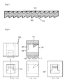
- Figure 3 is a perspective view illustrating a construction of a belt part 310 of a cable tie according to a preferred embodiment of the present invention.
- toothed blades which have different directions from each other, and the winding directions of the reel 370 are different when it is used together with the engaging head part 320 of a preferred embodiment of the present invention and when it is used together with the engaging head part 420 according to another preferred embodiment of the present invention.
- Figure 4 is a cross sectional view cut away along dotted line AB in the belt part 310 of the cable tie of Figure 3 according to a preferred embodiment of the present invention. As shown in Figure 4 , at both sides of the belt part 310 are disposed toothed blades 323 and 324 which have different directions.
- FIG. 5 is a 2D view illustrating an engaging head part 320 of the cable tie according to a preferred embodiment of the present invention.
- the engaging head part 320 of the cable tie according to a preferred embodiment of the present invention has a space in its interior, in which the belt part 310 surrounds and ties the cables to be arranged in the direction of the start inlet 329 and is inserted in the direction of the end inlet 331.
- the engaging head part 320 has a toothed blade 321 on its inner surface for the purpose of preventing the belt part 310, which has been inserted in the direction of the end inlet 331, from escaping.
- the belt part 310 inserted in the end inlet 331 does not protrude as it is blocked by means of the stopper wall 326 in the engaging head part 320, so it can be fixed in the engaging head part.
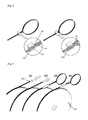
- Figure 6 is a perspective view before and after the belt part 310 is inserted into the end inlet 331 of the engaging head part 320 after the cables to be arranged are tied with the belt part 310 and the engaging head part 320 of the cable tie according to a preferred embodiment of the present invention.
- the start inlet 329 and the end inlet 331 of the engaging head part 320 according to a preferred embodiment of the present invention are placed on the facing surfaces in the engaging head part 320.
- the belt part 310 passes through the start inlet 329 of the engaging head part 320 and surrounds the cables to be tied and is inserted into the engaging head part 320 via the end inlet 331 and is fixed.
- the toothed blade directions are inter-engaged between the contacting surfaces folded while surrounding the cables to be arranged, so it is hard to push the start end 327 of the belt part to contact with the stopper wall 326 via the end inlet 331 of the engaging head part 320. So, the start part 327 of the belt part is pushed long enough to be easily inserted into the end inlet 331 of the engaging head part, and the engaging head part 320 is pushed in the direction of the belt part 310 while holding the facing and folded belt part 310, so the engaging head part 320 moves, and the folded belt 310 is introduced into the interior of the engaging head part 320.
- the belt part 310 passing through the engaging head part 320 remains with the toothed blades being engaged on the surface folded with the start end 327 of the contacting belt part, so the belt part 310 no more passes through the engaging head part 320 via the start inlet 329; however since the belt part 310 which has passed through the engaging head part 320 can be pulled out in the opposite direction that the start inlet 329 is passed, when the belt part 310 loosened via the engaging head part 320 a certain length long enough for an easier work and surrounding the cables to be arranged is pulled out in the opposite direction that it has passed through the start inlet 329 of the engaging head part, the cables to be arranged are tightened by means of the belt part 310 surrounding cables.
- the belt part 310 fixed at the engaging head part 310 is cut just in front of the start inlet 329, so the belt part 310 cut as much as needed for the cable arranging work is used, and the leftovers of the belt part 310 can be wound again on the reel 370.
- Figure 7 is a flow chart of a work process of tying the cables to be arranged using the belt part 310 and the engaging head part 320 according to a preferred embodiment of the present invention.
- the belt part wound in a form of the reel 370 is unwound, and the start end portion 327 is passed through the start inlet 329 of the engaging head part 320, and is made to the form of 302 and surrounds the cables to be tied, and is pushed toward the folded belt part 310 surrounding the cables for thereby forming a fixed knot like the form of 304.
- the belt part 310 is properly pulled in the opposite direction that it has passed through the engaging head part 320 depending on the thickness of the tied cables and is pulled out of the engaging head part 320, and the knot is tightened for thereby finishing the cable tying work, and the belt 310 remaining wound on the reel is cut in front of the start inlet 329 of the engaging head part 320 for thereby finally finishing the cable arranging work.
- FIG 8 is a 2D view illustrating an engaging head part 420 according to another embodiment of the present invention.
- the engaging head part 420 (hereinafter referred to engaging head part 2) according to another embodiment of the present invention, the start inlet 329 which is an opening past which the belt part 310 first passes through the engaging head part 2 (420) and the end inlet 331 which is an opening where the belt part 310 is inserted into the final engaging head part 2 (420).
- a separation plate 425 which separates a space past which the belt part passes through the start inlet 329 and a space in which the belt part 310 is inserted into the end inlet 331 and is accommodated.
- the toothed blades 426 in the direction of the space that the end inlet 331 is passed.
- the separation plate 425 in the engaging head part 2 (420) is connected to the wall of the opposite surface of the engaging head part 2 (420) at the sides of the start inlet 329 and the end inlet 331 or is partially connected to the side surface of it, so the portion of the toothed blades 426 of the end of the separation plate at the sides of the start inlet 329 and the end inlet 331 can be elastically bent into the through space of the start inlet 329 or the insertion space of the end inlet 331.
- Figure 9 is a perspective view illustrating a construction after the engaging head part 2 (420) is partially cut along the curved surface so as to well shown the 3D features of the engaging head part 2 (420) according to anther preferred embodiment of the present invention.
- Figure 10 is a perspective view before and after the belt part 310 is inserted into the end inlet 331 of the engaging head part 2 (420) after the cables to be arranged are surrounding using the engaging head part 2 (420) and the belt part 310 according to another embodiment of the present invention.
- the belt part 310 passes through the engaging head part 2 (420) via the start inlet 329 and surrounds the cables to be arranged, and is inserted via the end inlet 331 of the engaging head part 2 (420) and is fixed.
- the separation plate 425 in the engaging head part 2 (420) remains parallel from the passing through direction, so a space large enough in order for the belt part 310 to pass through the engaging head part 2 (420) is obtained. Therefore, there is no problems for the belt part 310 to passes through the engaging head part 2 (420) via the start inlet 329.
- the cables to be arranged are surrounded with the thusly passing through belt part 310, and the start end portion 327 of the belt is inserted into the end inlet 331 of the engaging head part 2 (420), so that the inserted start end portion 327 of the belt does not escape by means of the toothed blades 426 formed at the end of the separation plate 425 in the engaging head part 2 (420).
- the start end 327 of the belt is inserted into the interior of the engaging head part 2(420) via the end inlet 331, so it is pushed owing to the thickness of the belt part 310 into which the toothed blades 426 of the end of the separation plate 425 in the engaging head part 2(420), and then the separation plate 425 is pushed toward the through space of the start inlet 329 in the engaging head part 2(420) and is bent, and the corner portion at the side of the start inlet 329 of the bent separation plate 425 pressurizes the belt part 310 which passes through the start inlet 329 of the engaging head part 2(420) while being caught at the shoulders of the toothed blades of the passing belt part 310, so the belt part 310 no more moves in the passing direction via the start inlet 329; however in this state, the belt part 310 can be withdrawn in the opposite direction that the belt part 310 has passed through the start inlet 329 of the engaging head part 2(420) owing to the directional configuration between the toothed
- the belt part 310 surrounding the cables to be arranged after they are unwound and loosened via the engaging head part 2(420) with a lot of surplus lengths for easier work is pulled in the opposite direction that the start inlet 329 of the engaging head part 2(420) is passed through and is withdrawn, so the cables to be arranged are tightened by means of the belt part 310 surrounding the cables, and after the cables to be arranged are properly tightened, the belt part 310 fixed at the engaging head part 2(420) is cut just in front of the start inlet 329, and the belt part 310 remaining after the belt part 310 was used as much as needed for the cable arranging work is wound on the reel 370.
- Figure 11 is a flow chart of a work process of tying the cables, which are to be arranged, with the belt part 310 and the engaging head part 2(420) according to another embodiment of the preset invention.
- the winding direction of the belt part 310 wound on the belt reel 370 of Figure 11 is opposite to the winding direction of the belt part 310 wound on the belt reel 370 of Figure 7 .
- the belt part 310 wound in the shape of the reel 370 is unwound, and the start end portion 327 is passes through the start inlet 329 of the engaging head part 2(420) and surrounds the cables to be arranged, and the start end portion 327 of the belt part 310 is inserted into the end inlet 331 of the engaging head part 2(420) for thereby obtaining the configuration of 402, and the belt part 310 having passed via the engaging head part 2(420) so as to surround the cables, which are to be arranged, with enough lengths for an easier arranging work is pulled and withdrawn from the engaging head part 2(420) in the opposite direction that it has passed via the start inlet 329 of the engaging head part 2(420) depending on the thickness of the cables.
- the belt part 310 When the belt part 310 is pulled and withdrawn in the above mentioned manner, the belt part 310 surrounding the cables to be arranged properly tightens and ties the cables, and the belt part 310 fixed at the engaging head part 2(420) in a properly tightened state is cut just in front of the start inlet 329 of the engaging head part 2(420) for thereby finishing the cable arranging work.
- the belt part 310 remaining after a cutting work is wound on the reel 370 without leaving leftovers.
- the present invention can be well applied for the purpose of arranging cables in the course of various manufacture parts used for cables and can be applied for the use at home.
Landscapes
- Engineering & Computer Science (AREA)
- General Engineering & Computer Science (AREA)
- Architecture (AREA)
- Civil Engineering (AREA)
- Structural Engineering (AREA)
- Mechanical Engineering (AREA)
- Clamps And Clips (AREA)
- Package Frames And Binding Bands (AREA)
- Installation Of Indoor Wiring (AREA)
Applications Claiming Priority (2)
| Application Number | Priority Date | Filing Date | Title |
|---|---|---|---|
| KR1020100016958A KR101117457B1 (ko) | 2010-02-25 | 2010-02-25 | 버려지는 부분이 없는 길이 조절 케이블 타이 |
| PCT/KR2011/000974 WO2011105711A2 (fr) | 2010-02-25 | 2011-02-14 | Attache de câble à longueur réglable pouvant éliminer le gaspillage de celle-ci |
Publications (2)
| Publication Number | Publication Date |
|---|---|
| EP2541709A2 true EP2541709A2 (fr) | 2013-01-02 |
| EP2541709A4 EP2541709A4 (fr) | 2014-03-05 |
Family
ID=42179909
Family Applications (1)
| Application Number | Title | Priority Date | Filing Date |
|---|---|---|---|
| EP11747601.0A Withdrawn EP2541709A4 (fr) | 2010-02-25 | 2011-02-14 | Attache de câble à longueur réglable pouvant éliminer le gaspillage de celle-ci |
Country Status (6)
| Country | Link |
|---|---|
| US (1) | US20120311823A1 (fr) |
| EP (1) | EP2541709A4 (fr) |
| JP (1) | JP2013520954A (fr) |
| KR (1) | KR101117457B1 (fr) |
| CN (1) | CN102859821A (fr) |
| WO (1) | WO2011105711A2 (fr) |
Cited By (1)
| Publication number | Priority date | Publication date | Assignee | Title |
|---|---|---|---|---|
| DE102019200588A1 (de) * | 2019-01-17 | 2020-07-23 | Siemens Healthcare Gmbh | Kabelverbindungseinheit zum Anschluss an eine Gradientenspuleneinheit |
Families Citing this family (23)
| Publication number | Priority date | Publication date | Assignee | Title |
|---|---|---|---|---|
| KR101399742B1 (ko) * | 2012-03-06 | 2014-06-12 | 최윤성 | 케이블 타이 |
| KR102073595B1 (ko) * | 2012-09-26 | 2020-02-06 | 김호식 | 재사용 및 재활용성이 강화된 용도확장형 결속구 |
| US9266653B1 (en) | 2013-11-14 | 2016-02-23 | Stephen J. Housser | Flush cut tie device |
| USD723357S1 (en) | 2014-02-11 | 2015-03-03 | James M. Measner | Pipe hanger |
| KR101649419B1 (ko) * | 2014-12-05 | 2016-08-19 | 황문진 | 길이조절이 자유로운 케이블타이 |
| CN104859945A (zh) * | 2015-04-17 | 2015-08-26 | 柳州蔚园塑料彩印包装有限责任公司 | 塑料线扣 |
| WO2017083965A1 (fr) * | 2015-11-17 | 2017-05-26 | Rivard Louis-Philippe | Nécessaire de sangle et raccord à attache autobloquante |
| KR200481773Y1 (ko) * | 2016-03-03 | 2016-11-08 | 프타 주식회사 | 절개형 케이블 타이 |
| KR200485555Y1 (ko) * | 2016-06-20 | 2018-03-08 | 주식회사 엔케이이씨 | 케이블타이 |
| USD812459S1 (en) * | 2017-04-06 | 2018-03-13 | Joseph Gerald Miller | Lock for ratcheting tie system |
| CN109484767A (zh) * | 2017-09-13 | 2019-03-19 | 黄铭德 | 单条束带可多条使用的方法及其构造 |
| FR3073503B1 (fr) | 2017-11-14 | 2019-11-22 | Hellermanntyton Gmbh | Appareil automatique manuel pour poser des colliers de serrage |
| TWI636777B (zh) * | 2017-11-22 | 2018-10-01 | 賈秉坤 | Easy to tighten tight band |
| WO2019176970A1 (fr) * | 2018-03-16 | 2019-09-19 | 京セラドキュメントソリューションズ株式会社 | Collier d'attache |
| USD939791S1 (en) * | 2018-03-27 | 2021-12-28 | Maurice Myerson | Scoop, holder and base combination |
| US11511894B2 (en) | 2019-09-26 | 2022-11-29 | Hellermanntyton Corporation | Cable tie application tool |
| CN112124787B (zh) * | 2020-08-26 | 2022-07-12 | 平高东芝(河南)开关零部件制造有限公司 | 一种扎带组件 |
| ES2963625T3 (es) * | 2020-09-17 | 2024-04-01 | Meilleur Co Ltd | Herramienta de unión |
| EP4163215A1 (fr) | 2021-10-01 | 2023-04-12 | HellermannTyton GmbH | Dispositif d'outil de fardelage automatique optimisé pour une plage d'épaisseurs de sangles d'une seule pièce |
| USD1012641S1 (en) | 2021-10-25 | 2024-01-30 | Aptiv Technologies Limited | Tool nosepiece |
| US12157240B2 (en) | 2021-10-26 | 2024-12-03 | Hellermanntyton Corporation | Severing a cable tie with a rounded cut |
| DE202022002179U1 (de) | 2022-10-06 | 2024-01-11 | Hellermanntyton Gmbh | Automatische Bündelwerkzeugvorrichtung mit Führungseinheit für verformte und/oder lose einteilige Bänder |
| USD1078450S1 (en) * | 2024-07-09 | 2025-06-10 | Xinmiao Huang | Cable tie |
Family Cites Families (33)
| Publication number | Priority date | Publication date | Assignee | Title |
|---|---|---|---|---|
| US3197829A (en) * | 1962-03-08 | 1965-08-03 | Panduit Corp | Binder strap |
| US3224056A (en) * | 1963-11-29 | 1965-12-21 | Park Plastics Co Inc | Strap seal |
| US3258819A (en) * | 1964-09-21 | 1966-07-05 | Weckesser Co | Cable clamp |
| US3530544A (en) * | 1967-10-30 | 1970-09-29 | Thomas & Betts Corp | Cable bundling strap |
| US3653099A (en) * | 1970-08-03 | 1972-04-04 | Amp Inc | Bundle tie device |
| CH534085A (fr) * | 1971-02-01 | 1973-02-28 | Ipp Ind Polymer Proc S A | Lien et procédé pour sa fabrication |
| US3816878A (en) * | 1971-11-10 | 1974-06-18 | Panduit Corp | Cable tie |
| US3747164A (en) * | 1972-11-01 | 1973-07-24 | Thomas & Betts Corp | Releasable self-locking bundling strap |
| GB1427051A (en) * | 1973-08-31 | 1976-03-03 | Bowthorpe Hellermann Ltd | Cable ties |
| US3909884A (en) * | 1975-02-10 | 1975-10-07 | Weckesser Co | Wedge lock cable clamp |
| JPS60182360U (ja) * | 1984-05-14 | 1985-12-03 | 森谷 弘 | 締着具 |
| JPS6133950A (ja) * | 1984-07-18 | 1986-02-18 | 株式会社 トスカ | 結束バンド装置 |
| DE3525351C2 (de) * | 1985-07-16 | 1994-09-15 | Raymond A Gmbh & Co Kg | Kabelbinder |
| JPH0746855Y2 (ja) * | 1990-08-29 | 1995-10-25 | 矢崎総業株式会社 | 結束具 |
| JPH0754647Y2 (ja) * | 1990-11-27 | 1995-12-18 | 仁礼工業株式会社 | 電線等の結束具 |
| JPH0486034U (fr) * | 1990-11-30 | 1992-07-27 | ||
| JP2566920Y2 (ja) * | 1992-09-11 | 1998-03-30 | 矢崎総業株式会社 | バンドクランプ |
| EP0742159A1 (fr) * | 1995-05-11 | 1996-11-13 | Kun Sheng Chang | Dispositif de courroie de cerclage |
| CN2231219Y (zh) * | 1995-05-31 | 1996-07-17 | 张坤生 | 束紧带的捆绑带头 |
| KR970007326U (ko) * | 1995-07-31 | 1997-02-21 | 케이블 타이의 결합구조 | |
| DE29613832U1 (de) * | 1996-08-09 | 1996-10-02 | Chang, Kun-Sheng, Taipeh/T'ai-pei | Bindeeinrichtung |
| JPH1141759A (ja) | 1997-07-24 | 1999-02-12 | Sumitomo Wiring Syst Ltd | 結束バンドの組立方法 |
| IT238124Y1 (it) * | 1997-12-17 | 2000-09-29 | Brentini Attilio | Etichetta perfezionata associabile ad un articolo di commercio perl'emissione di un segnale di allarme e relativo dispositivo per il |
| US6047448A (en) * | 1998-07-30 | 2000-04-11 | Arnold; Phillip F. | Bundling strap system |
| CN2338301Y (zh) * | 1998-08-27 | 1999-09-15 | 林海鸥 | 捆扎扣带 |
| US6070304A (en) * | 1998-10-13 | 2000-06-06 | Lii; Yeon Shin | Cable for cable tying device |
| WO2001017874A1 (fr) * | 1999-09-04 | 2001-03-15 | Garcia De La Pena Razquin Emma | Dispositif permettant de couper la partie de languette depassant d'un collier de serrage |
| JP2001322667A (ja) * | 2000-05-16 | 2001-11-20 | Asahi Kasei Corp | 結束バンド |
| US20030066169A1 (en) * | 2001-10-09 | 2003-04-10 | Chiou Shyong Liu | Fastening belt capable of disassembling |
| KR100559591B1 (ko) * | 2003-07-02 | 2006-03-15 | 현대자동차주식회사 | 케이블 타이 |
| KR200387790Y1 (ko) * | 2005-02-11 | 2005-06-27 | 이봉기 | 길이조절 케이블타이 |
| JP2007091295A (ja) * | 2005-09-29 | 2007-04-12 | Tokyo Ootomakku Kk | 結束具及びその結束用固定具,結束バンド |
| KR100845579B1 (ko) | 2007-12-12 | 2008-07-16 | 주식회사 에스엠티씨 | 케이블 타이 |
-
2010
- 2010-02-25 KR KR1020100016958A patent/KR101117457B1/ko not_active Expired - Fee Related
-
2011
- 2011-02-14 US US13/580,690 patent/US20120311823A1/en not_active Abandoned
- 2011-02-14 CN CN2011800112459A patent/CN102859821A/zh active Pending
- 2011-02-14 JP JP2012554895A patent/JP2013520954A/ja active Pending
- 2011-02-14 WO PCT/KR2011/000974 patent/WO2011105711A2/fr not_active Ceased
- 2011-02-14 EP EP11747601.0A patent/EP2541709A4/fr not_active Withdrawn
Cited By (2)
| Publication number | Priority date | Publication date | Assignee | Title |
|---|---|---|---|---|
| DE102019200588A1 (de) * | 2019-01-17 | 2020-07-23 | Siemens Healthcare Gmbh | Kabelverbindungseinheit zum Anschluss an eine Gradientenspuleneinheit |
| US11255936B2 (en) | 2019-01-17 | 2022-02-22 | Siemens Healthcare Gmbh | Cable connection unit for connection to a gradient coil unit |
Also Published As
| Publication number | Publication date |
|---|---|
| WO2011105711A3 (fr) | 2012-01-19 |
| US20120311823A1 (en) | 2012-12-13 |
| KR20100029805A (ko) | 2010-03-17 |
| CN102859821A (zh) | 2013-01-02 |
| JP2013520954A (ja) | 2013-06-06 |
| WO2011105711A9 (fr) | 2011-12-01 |
| KR101117457B1 (ko) | 2012-02-29 |
| EP2541709A4 (fr) | 2014-03-05 |
| WO2011105711A2 (fr) | 2011-09-01 |
Similar Documents
| Publication | Publication Date | Title |
|---|---|---|
| EP2541709A2 (fr) | Attache de câble à longueur réglable pouvant éliminer le gaspillage de celle-ci | |
| US6560822B2 (en) | Low profile cable tie with prebent strap | |
| KR101990778B1 (ko) | 재사용이 가능한 케이블 타이 | |
| US20060096066A1 (en) | Side notched cable tie | |
| KR101399742B1 (ko) | 케이블 타이 | |
| KR101683171B1 (ko) | 전선 정리기 | |
| JP6127920B2 (ja) | ワイヤハーネス及び結束具 | |
| KR101951334B1 (ko) | 케이블 타이 장치 | |
| CN104029913B (zh) | 捆扎带 | |
| JPH0735269A (ja) | 結束バンド | |
| JP6166993B2 (ja) | 合成樹脂製結束バンド | |
| KR20150001045U (ko) | 케이블 타이 | |
| KR102076230B1 (ko) | 케이블 타이 장치 | |
| KR200277447Y1 (ko) | 고정밴드 | |
| JP6924573B2 (ja) | 巻付具 | |
| JPH0488613A (ja) | 変圧器用巻枠 | |
| KR101292638B1 (ko) | 결속용 금속 밴드 | |
| KR101778125B1 (ko) | 전선 결속부재 | |
| JP6887695B2 (ja) | 樹脂製部材 | |
| US20130025615A1 (en) | Handling aid for dental floss | |
| WO2007102828A1 (fr) | Attache de cable a encoches laterales | |
| KR20090061908A (ko) | 케이블 타이용 밴드 | |
| US20030019654A1 (en) | Cord organizer | |
| JP2005082237A (ja) | 止め具及びこれを用いた結束部材 | |
| JP2017212768A (ja) | ワイヤーハーネス用結束部材、結束部材付ワイヤーハーネス |
Legal Events
| Date | Code | Title | Description |
|---|---|---|---|
| PUAI | Public reference made under article 153(3) epc to a published international application that has entered the european phase |
Free format text: ORIGINAL CODE: 0009012 |
|
| 17P | Request for examination filed |
Effective date: 20120918 |
|
| AK | Designated contracting states |
Kind code of ref document: A2 Designated state(s): AL AT BE BG CH CY CZ DE DK EE ES FI FR GB GR HR HU IE IS IT LI LT LU LV MC MK MT NL NO PL PT RO RS SE SI SK SM TR |
|
| DAX | Request for extension of the european patent (deleted) | ||
| A4 | Supplementary search report drawn up and despatched |
Effective date: 20140203 |
|
| RIC1 | Information provided on ipc code assigned before grant |
Ipc: F16B 2/08 20060101ALI20140128BHEP Ipc: H02G 3/30 20060101AFI20140128BHEP |
|
| STAA | Information on the status of an ep patent application or granted ep patent |
Free format text: STATUS: THE APPLICATION IS DEEMED TO BE WITHDRAWN |
|
| 18D | Application deemed to be withdrawn |
Effective date: 20150901 |